1. Introduction
An ever increasing urban population, sky-scraping prices of the conventional fuels and stringent emission control laws to create a carbon-free global economy are the driving forces for research and development in the field of electromobility. Unlike trains and electric buses with pantographs, the road bounded electric vehicles need extensive energy storage devices. The charging infrastructure and the capacity of energy storage device for maximum travel range are the main challenges in the development of electric cars.
Due to their high energy and power densities, lithium-ion batteries (LIBs) are an excellent choice for energy storage and traction for electric vehicles (EVs), however the safety of vehicle occupants after road accidents are a major concern involving LIBs. Large mechanical deformations after a crash or intrusions of sharp objects into the battery damage the interiors of the cells. This could cause an internal short circuit between electrodes and current collectors or between electrodes and separators of the cell. Consequently, the sudden rise in local temperature can cause thermal runaway, fire or explosion [
1].
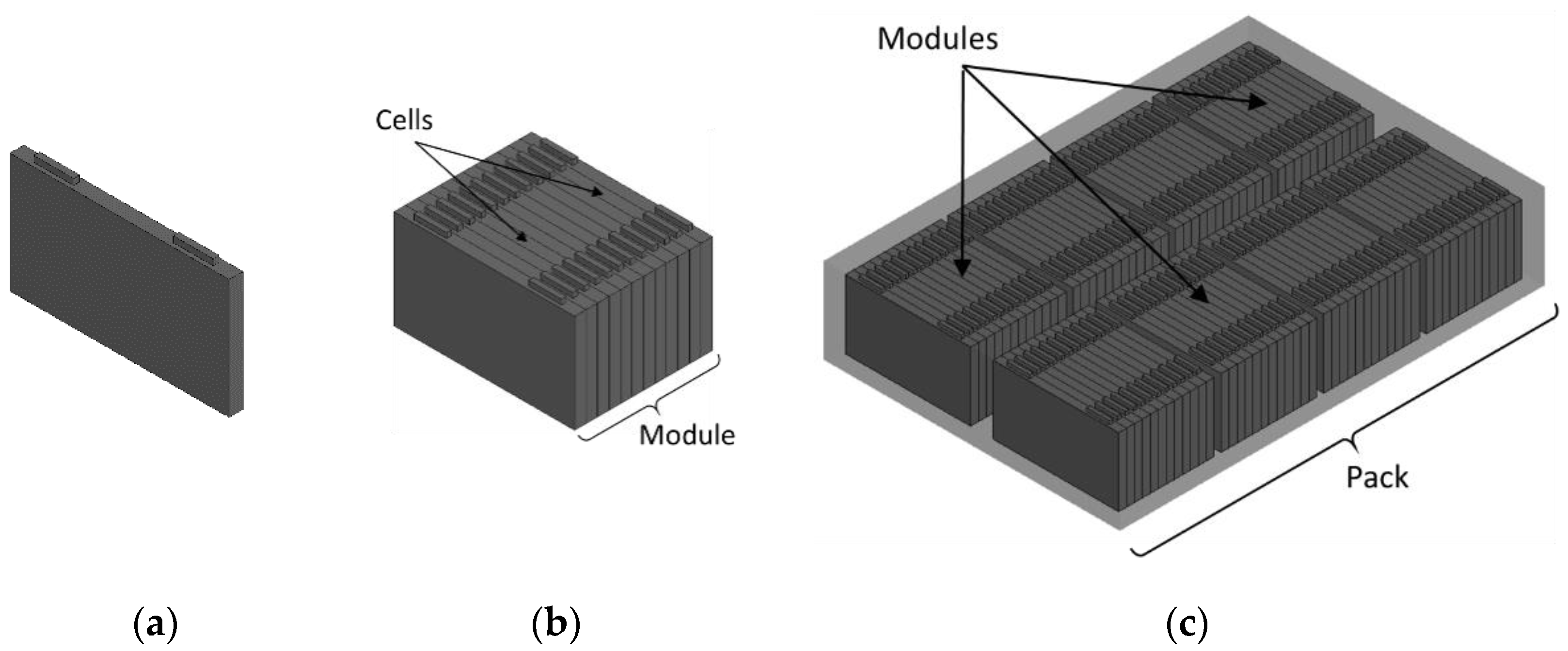
A battery system is protected by a chassis or a body of an EV during a crash. A battery system consists of a battery pack and other essential devices such as a control mechanism, a thermal management system etc. A typical battery pack contains several battery modules and the battery modules are made up of a number of battery cells. To understand the root cause of short-circuits that occur during a crash, it is necessary to study the behaviour of the system at all levels of battery including cell, module and pack. To predict the response of the battery under different abuse scenarios, a battery must undergo a series of safety tests recommended by national and international norms and regulations.
Ruiz et al. [
1] reviewed the international abuse testing standards and regulations. The safety tests can be mainly divided into electrochemical, thermal and mechanical abuse tests. Different norms suggest different tests as well as the level on which the tests should be conducted i.e., cell, module or pack level as shown in
Figure 1.
Abuse tests are time consuming, hazardous and expensive. To fulfil the requirements from legislative and consumer tests and to reduce development time and cost, simulative methods are implemented in battery design [
2]. Other advantages of the simulation methods are to foresee which parameter could influence the precision of the analysis and how to investigate the discrepancies between test results and simulations [
3]. Furthermore, a simulation-based analysis increases the quality by optimization and avoids over-engineering.
In recent years, various studies containing FE simulation methods have been published for assessment of the mechanical behaviour of LIB cell under impact and crash loading conditions. Studies involve various shapes and sizes of batteries including cylindrical cells [
4], pouch cells [
5] or prismatic cells [
6]. The studies also incorporate the various indenter shapes e.g., spherical indenter [
7] or cylindrical indenter [
4], etc. The impact test on module level is also conducted and simulated by Shi et al. [
8]. The mechanical models of battery cells have been developed by Breitfuss et al. [
9] using a microscopic approach where all components of the batteries including cathodes, anodes and separator layers were separately modelled. Another approach is discussed by Sahraei et al. [
7], in which one single component was modelled with combined mechanical material properties of all these component layers.
In this current study, different modelling approaches from various publications are evaluated and compared by modelling a sample pouch cell using a finite element method. At first, existing modelling approaches are described with their merits and demerits in terms of complexity of modelling and simulation time. Each method is then verified by modelling a suitable sample battery cell and by performing parametric studies. The outcomes of each study are discussed in detail. Finally, the work concludes with a summary of advantages of each method and identification of further development areas.
2. Battery Modelling
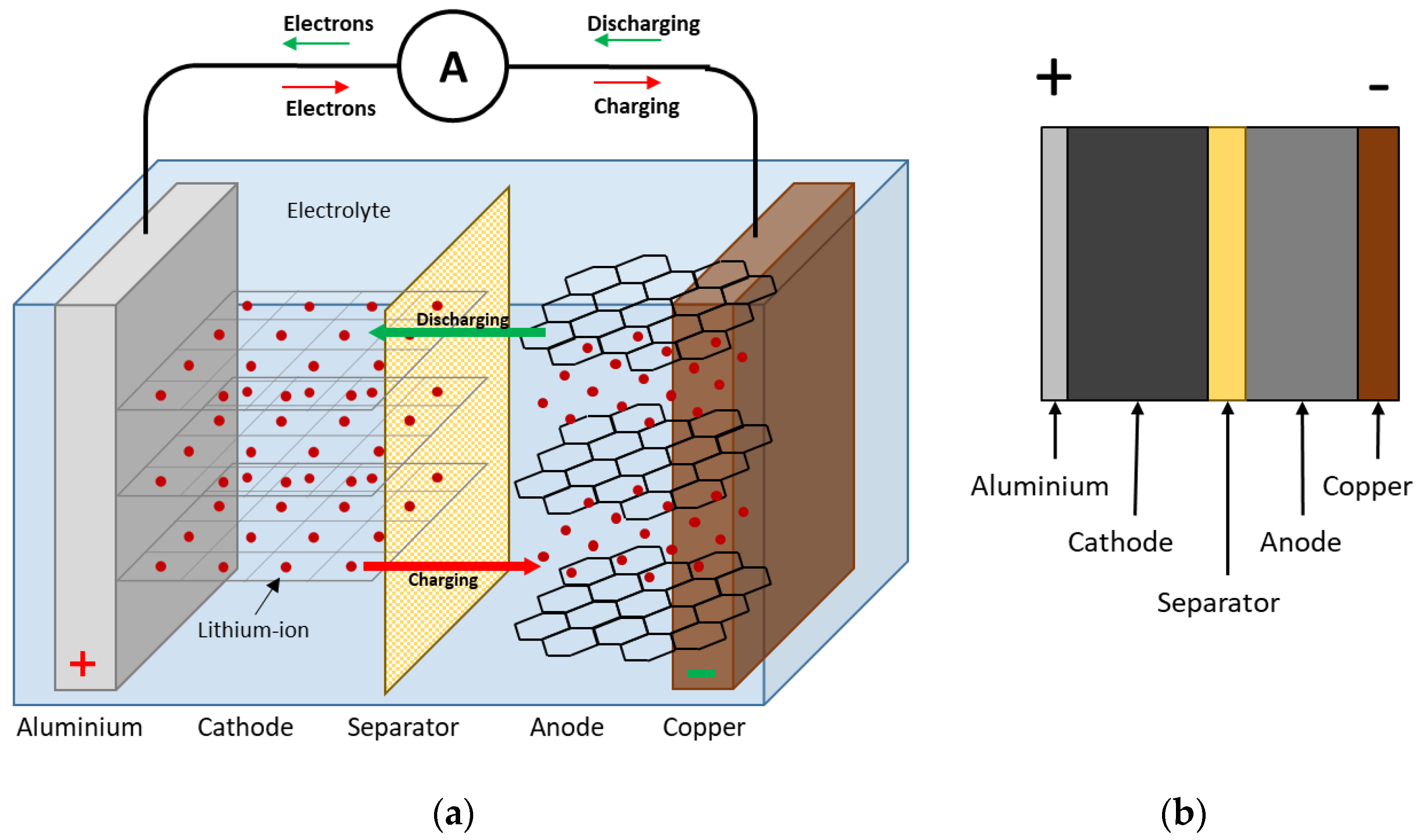
A typical LIB cell is made up of several thin layers of positive and negative electrodes, current collectors, separators and electrolytes. Typically, the positive electrode or the active cathode material is lithium metal oxides coated on both sides of aluminium current collectors. Similarly, the negative electrode or active material of anode is graphite which is coated on both sides of the copper current collectors as shown in
Figure 2.
The layer of separation between electrodes serves the purpose of isolation and allows the transfer of lithium ions during charging and discharging. This set of components known as a compartment repeats multiple times in the battery cell. All these component layers together are called a jellyroll or stack of electrodes. The jellyroll or stack is then covered with metal or a plastic casing depending on the type of cell and the casing is then filled with electrolyte fluid. Generally, the Pouch cell is made up of rectangular stack of electrodes covered in aluminium polymer foil. In the case of cylindrical cells, the layers are wound together in the form of a roll with a hard metal casing. On the other hand, prismatic cells could be made up of rolled or stacked electrodes with a hard casing [
10]. The electrical components such as bus bars are then welded to the cell ends for connectivity to other cells. Cooling components such as cooling plates or heat sinks are added to the assembly for thermal management.
The modelling of a battery cell can be done in several methods depending on the simulation type, complexity of the model, required accuracy and computational capacity. Depending on the field of the application, a modelling method can be chosen. Based on a comprehensive study by Sahraei et al. [
11], an onset of the short circuit as a result of abuse can be predicted by mechanical modelling of the battery cell using a finite element method. A simulation of a ball indentation test can show the mechanical failure of the battery cell associated with failure of a separator, which triggers the short circuit in the cell. Only mechanical modelling is discussed in this paper.
Another important aspect of modelling the battery cell is the complexity of the model. The components of the battery cell (e.g., electrolyte, binders or bus bars) are sometimes not considered in the modelling for simplification. Another example is the modelling of electrode windings in the case of cylindrical cells, where by concentric circles of electrodes can be modelled instead of convolutes of rolled electrodes [
11]. For a demonstration of the different modelling approaches to the battery, a pouch call is selected in this study which consists of a stack of electrodes and a separator. As studied by Sahraei et al. [
5], the casing or foil of the pouch cell does not contribute much to the integrity of the battery cell in the lateral direction; therefore, in this study only jellyroll is modelled.
The capacity of the available computing power also plays an important role in deciding the modelling approach. The workstation with Windows 10 was used for simulations in this study which has an Intel® Xeon® Gold 5122 CPU @ 3.60 GHz and 3.59 GHz processors. All Simulations were performed using 8 CPU’s and 64 GB RAM. For mechanical simulations of a battery cell in this study, an explicit solver from LS DYNA was selected.
3. Modelling Approaches
The modelling of the battery cell is categorised by the structure of the jellyroll as well as by the behaviour of the materials under different load directions. The structural modelling of the battery cell with a finite element method can be done with mainly two modelling approaches, namely homogeneous or macroscopic and heterogeneous or microscopic modelling [
12]. Furthermore, there are some other techniques to build the FE model such as hybrid modelling and sandwich modelling as shown in
Figure 3.
Each of these approaches can be further categorised on the basis of directional behaviour of material, i.e., either isotropic or anisotropic. In the following sections all four modelling approaches are discussed in detail and then compared by modelling a sample pouch cell. Furthermore, a symmetric partial modelling approach is also discussed for optimisation of the developed models.
3.1. Heterogeneous Modelling Method
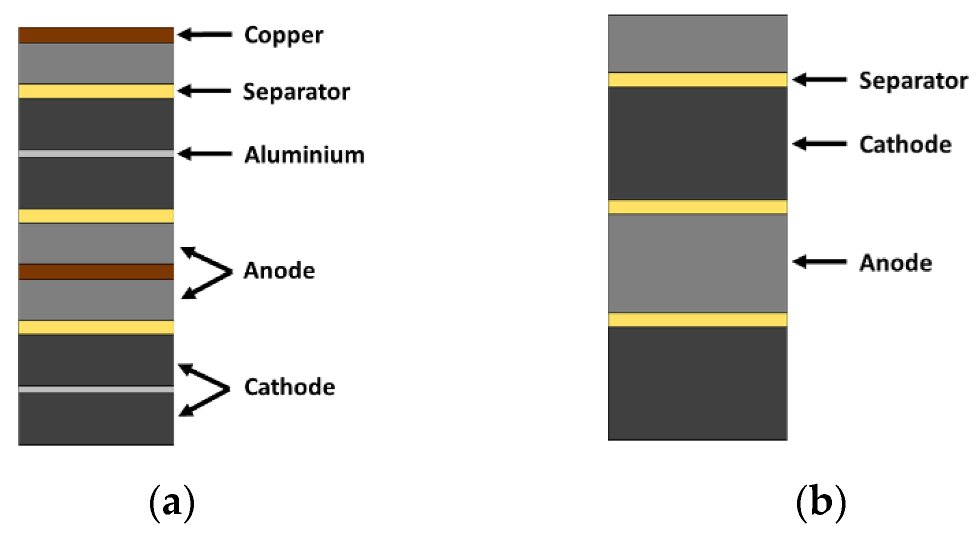
The heterogeneous modelling technique is also called a microscopic or layered modelling technique in which all component layers within a battery cell, i.e., anode, cathode and separator layers are separately created, depicting a real LIB cell. The component layers are assigned with individual thicknesses and distinct mechanical material properties such as density, modulus of elasticity, yield, strength etc. The anode or cathode are made up of active materials and current collectors [
12]. In one method the current collectors (e.g., copper foil, aluminium foil and active materials) are also modelled separately as shown in
Figure 4a. In another method, the electrodes can be modelled together with their respective active materials as a single part as shown in
Figure 4b.
In this study, the active materials and current collectors are modelled separately and active materials for the cathode and active materials for the anode are designated as cathode or anode as per
Figure 4a. The main advantage of the modelling with this method is the level of detail. Simulation results of individual layers of the components could be obtained by this method. However, the modelling is complex and requires various material properties to be defined. Additionally, there is a high numerical effort which prevents its use for optimization methods.
3.2. Homogeneous Modelling Method
The homogenous or macroscopic modelling technique is the simplified method of modelling a battery cell. In this method a single part is modelled representing the complete jellyroll or stack of the battery cell components. Thicknesses and material properties of individual layers are combined and assigned to this single part [
12]. To determine the modulus of elasticity for the homogeneous material (
) the mean value method of Voight can be used. This procedure considers the respective volume ratios (
) and the modulus of elasticity (
) of the individual cell components [
12] as shown in Equation (1).
A mean value method is also used to calculate the tensile strength (
), which is explained in a publication by Sahraei et al. [
5] as mentioned in Equation (2).
There are five different components in the cell, namely copper, aluminium, anode, cathode and separator. Therefore
represents the component,
stands for the respective thickness of the component and
for the number of layers of the component. For a more detailed definition of the materials, a stress-strain diagram is required. This can be obtained by performing a compression test of the bare cell.
In comparison with the heterogeneous modelling method, this method is simple and easy because fewer material inputs are required to create the model. However, the deformation of individual layers is not visible in this method.
3.3. Hybrid Modelling Method
As the name suggests, a hybrid modelling technique is a combination of a heterogeneous and homogeneous modelling method. In this method the battery cell is partially resolved. This means that only a few layers are modelled separately. The rest of the stack of layers is then modelled as a single homogeneous part. The resolved layer area is assigned with individual properties and a homogeneous part with combined properties. Turner et al. [
12] evaluated this modelling method with a different number of resolved layers. They reported that in their model, when four out of eight sets of stack layers were resolved, the results were consistent. Therefore, in this study only half of the stack is resolved and the rest is modelled as a single part.
This method is relatively less complex than the heterogeneous method. The results of the first few layers, where the indentation or intrusion takes place, are possible to obtain. However, this technique requires the input data of a heterogeneous model as well as a homogenous model.
3.4. Sandwich Modelling Method
Another method of modelling is known as a sandwich modelling technique. In this method all layers of the same component are combined together to form a homogeneous layer of that component with combined thickness
).
For example, Zhang et al. [
13] found all anode layers are stacked together and modelled as one single homogeneous part with the combined thicknesses of an anode. Similarly, all cathodes, current collectors and separators are also combined to form one cathode, one cathode current collector, one anode current collector and two separators.
In this way the number of parts in the model are reduced as compared to a heterogeneous or hybrid model, which makes the model less complex.
3.5. Partial Modelling Method
The partial modelling method is an extension of each modelling method. It deals with the modelling of a partial battery cell instead of complete dimensions of the battery cell as discussed with previously mentioned methods. When the battery cell is symmetric around one or more of its own axes, the partial modelling method can be used. There are very few publications available for battery modelling with this method. For example, Zhang et al. [
13] implemented this technique for a representative sandwich model in their publication. This method can be applied along with any modelling technique to reduce the number of elements in a simulation model.
3.6. Anisotropic Material Properties of Separator
The material of the separator is anisotropic in nature. There are many publications related to mechanical modelling of a battery cell, but anisotropy of the separator material is rarely considered while modelling. The investigations of the Oak Ridge National Laboratory [
12] and of Sahraei et al. [
14] prove that the separator exhibits an anisotropic behaviour and its modelling leads to realistic results. The anisotropic material can be described by Equations (4) and (5) as discussed by Sahraei et al. [
14]. The hardening curve is modelled as follows:
where
is the yield stress,
is the initial yield limit and
is the engineering strain. The failure criterion is when
where
are the normal strains in tension in Equation (3).
4. FE Simulations
To compare modelling techniques described in the previous section, a sample pouch cell with 40 mm length, 40 mm width and 5.152 mm thickness was selected for modelling. For simplification of the mechanical model of the battery cell, the liquid electrolyte and electrical connections were not modelled. The effect of the state of charge (SoC) and lithium content on the mechanical properties of the active materials were not considered in this study. The change in volume of the battery cell as a result of lithiation was also not considered in this study.
A spherical indentation test was chosen for the simulations. With this test the increased force can be observed along with the failure of the cell indicated by the sudden drop in force. In order to address the differences in the results with all modelling techniques, uniform parameters should to be applied to all simulations. First, the settings are described, which are common for all models.
In a spherical indentation test, a punch with a spherical head was pressed on the battery cell until cell failure was observed. The punch is normally made up of steel material, which is much harder compared to a battery cell. In order to avoid any deformations of the spherical punch, it was modelled as a rigid body in all simulations. For this purpose the material card with the description MAT_020_RIGID was used from the material library of LS DYNA [
15]. A radius of 6.35 mm was chosen for the sphere [
5]. The small diameter of sphere permits an increase of the applied pressure and the associated force on the cell surface, thus inducing an early failure of the cell. To minimize the number of elements in the model, shell elements were assigned to the sphere. The mesh density was selected as 11 for suitable element size, resulting in 726 shell elements. In addition, a mandatory shell thickness of 0.1 mm was assigned to the elements.
A motion of the sphere in z-direction (i.e., normal to the cell lateral direction) was enabled using the keyword BOUNDARY_PRESCRIBED_MOTION_RIGID [
16]. Constant velocity of 1 m s
−1 was defined to depict the movement of the punch. In order to be considered as quasi-static, it was specified that the proportion of kinetic energy must not exceed 1% of the total energy [
17]. To keep the cell in place during the indentation process, the movements and rotations of the cell were constrained. A planer RIGIDWALL was created underneath the battery cell.
The battery cell models were developed using quadratic solid elements with eight nodes in all modelling methods. The nodes along the sides of the cell were held in place by constraining movements and rotations of the nodes in all directions. The CONTACT_AUTOMATIC_SURFACE_TO_SURFACE card was used to define the contact interface between the sphere and the battery cell. A coefficient of friction (μ) was assumed to be 0.3. The material models and contact interfaces within the battery cell selected for each modelling method are described in the following section.
4.1. Heterogeneous Cell Model
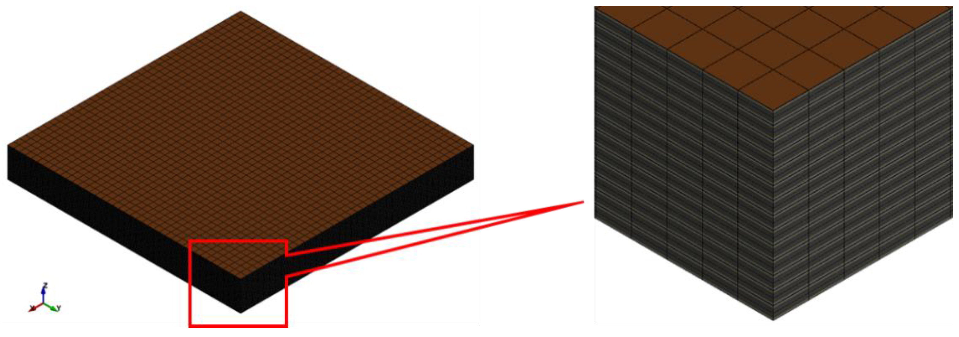
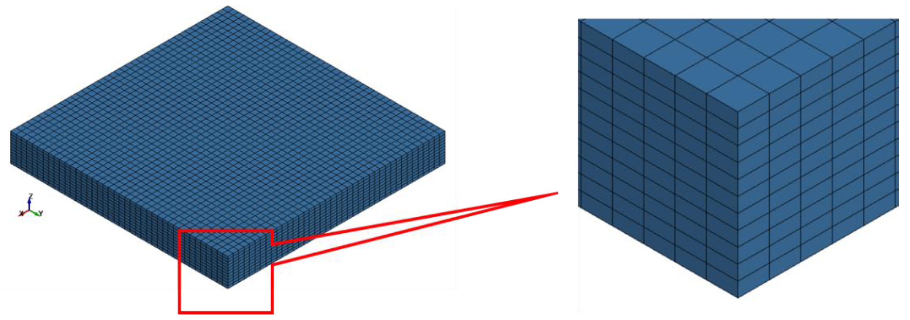
For heterogeneous modelling, the model of the battery cell was developed with 112 layers, which corresponds to a pouch cell with 14 compartments or sets of components as shown in
Figure 5. A single set of components represents eight layers: a copper current collector, aluminium current collector, two layers of anode (active materials for anode), two layers of cathode (active materials for cathode) and two layers of separator.
The thickness and material properties of each layer were referred from the report of the Oak Ridge National Laboratory [
12]. The components were discretised with volume elements 1 mm in size. With respect to thickness direction, only one element was modelled for each component. In total there were 179,200 volume elements in the heterogeneous model. The CONTACT_AUTOMATIC_ONE_WAY_ SURFACE_TO_SURFACE_TIEBREAK contact card [
16] was used to establish contact between the individual components.
A variety of material models are available to simulate the material properties of the individual components. The simulation of the material behaviour of copper, aluminium and separator material was achieved by using the MAT_024_PIECEWISE_ LINEAER_PLASTICITY material card [
16]. This material card represents an isotropic elastic–plastic behaviour including a stress–strain curve [
15]. Furthermore, the definition of the failure strain is possible. In order to include and visualize the destruction of the separator, an additional material card, MAT_000_ADD_EROSION was added to the model. When the failure criterion for the separator was reached (failure strain, ε = 40%), the affected element was deleted from the calculation. The anode and cathode were assigned with the isotropic material card MAT_063_CRUSHABLE_FOAM. This card intends to simulate the behaviour of a foam-like material. All material properties were referred from Table 16 from the report of the Oak Ridge National Laboratory [
12].
In another model to evaluate the effect of anisotropy on the separator, a material card MAT_126_MODIFIED_-HONEYCOMB was assigned to the separator instead of MAT_024. This MAT_126 card allows the mapping of the nonlinear elastic–plastic behaviour of material [
16]. For this, a total of six parameters associated with stress–strain curves are required. These include the elasticity and shear moduli for the respective axial directions. The transverse behaviour (x and y directions) of the separator are very similar and therefore can be considered identical. The required shear moduli can be calculated according to the formula [
15]:
where
is the elastic shear modulus for the fully compacted honeycomb material,
is the Young’s modulus and
is the Poisson’s ratio.
For the Young’s modulus in the z direction, the value of z = 42 MPa was used and for the transverse directions xy = 38 MPa. This results in the respective values of z = 16.15 MPa and xy = 14.62 MPa for the shear modulus.
4.2. Homogeneous Cell Model
In the homogeneous modelling strategy, the sample battery cell model was created as a single part as shown in
Figure 6. The cell is discretised into a total number of 17,600 volume elements. The material card MAT_063_CRUSHABLE_FOAM was assigned to the model. The homogenised material properties of the cell were calculated using the previously mentioned mean value formulae from
Section 3.2.
Substituting the respective values from Table 16 from [
12], the modulus of elasticity was calculated to be 553.96 MPa and the tensile strength was 37.58 MPa. As the stress–strain diagram was not available for the battery cell used here, the material behaviour of a geometrically similar battery cell was used, which is investigated by Sahraei et al. [
7]. It is assumed that the mechanical properties with regard to compression are identical to a small cell from their study due to similar dimensions. The Poisson’s ratio for the entire cell was 0.01 [
5].
In order to consider the anisotropic separator, another model was developed with the material card MAT_126. The anisotropic material behaviour with MAT_126 has been already investigated by Sahraei et al. [
14]. The E-moduli through thickness and plain compression can be calculated by referring to the graphs of their experiment. The E-modulus in the through thickness direction was considered
z = 57 MPa and the E modulus in the plain compression direction was
xy = 90 MPa. The shear modulus was calculated according to Equation (3). Due to Poisson’s ratio of ϑ = 0.01, it can be neglected for this calculation. This results in a value of
z = 28.5 MPa and
xy = 45 MPa for the respective shear moduli through thickness and plain directions.
4.3. Hybrid Cell Model
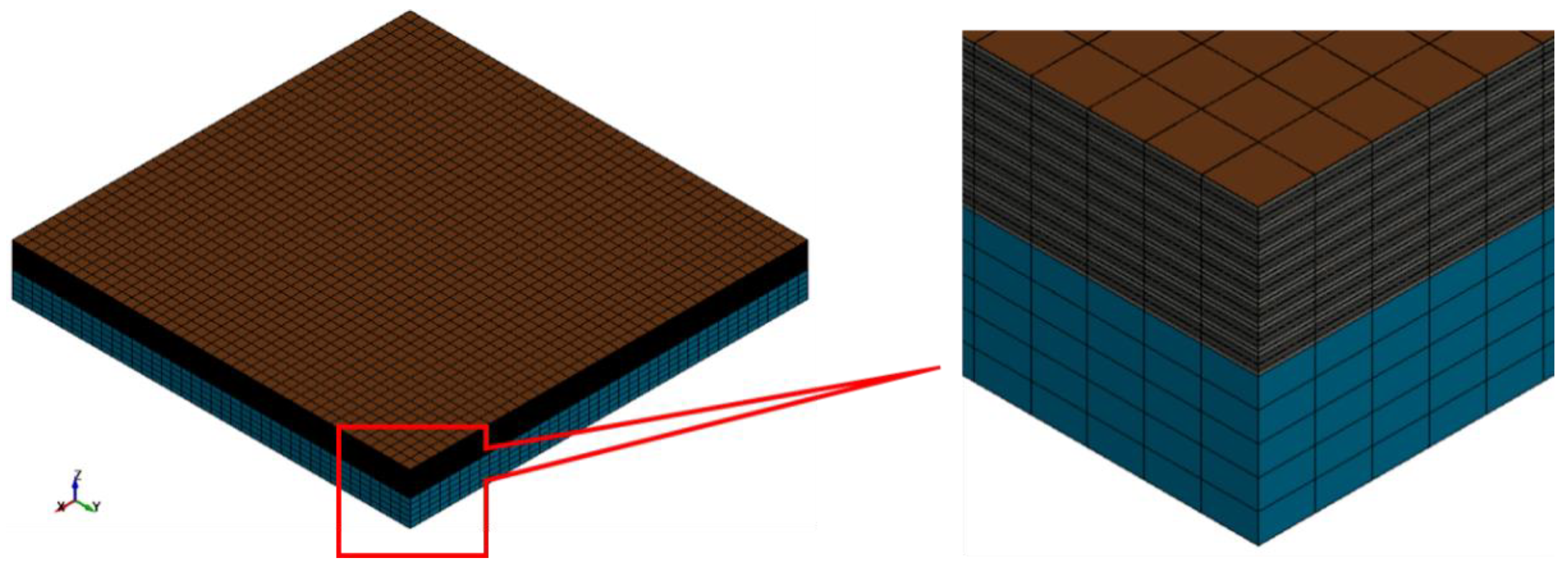
A model created with this hybrid technique was a mixture of the heterogeneous and the homogeneous model as shown in
Figure 7. The simulation settings of the upper resolved layers of the hybrid model are identical to the heterogeneous model from
Section 4.1 and the settings of the lower part of the hybrid model were similar to that of the homogenous model described in
Section 4.2.
The model was made up of 97,600 volume elements. The interaction between the upper resolved layers and the lower homogenised part was defined by the contact algorithm AUTOMATIC_ONE_WAY_SURFACE_TO_SURFACE_TIEBREAK [
16]. The anisotropic behaviour of the separator and the homogeneous part of the cell was also simulated with the material model MAT_126.
4.4. Sandwich Cell Model
The cell model created using this technique was slightly different than other methods. The representative sandwich model consisted of eight parts and the thickness of each part was equivalent to the thickness of 14 layers of that component. The cell was made up of two parts anode, cathode and separator and one part aluminium and copper as shown in
Figure 8.
The model was discretised into 12,800 volume elements. The material card MAT_024 was assigned to copper, aluminium and separator parts whereas the material card MAT_063 was assigned to the active materials of the anode and cathode. Similarly, MAT_000_ADD_EROSION was assigned to the separator. Contact interface for the individual layers was also achieved by CONTACT_AUTOMATIC_ONE_WAY_SURFACE_TO_SURFACE_TIEBREAK. To observe the anisotropic nature of the separator, the material card MAT_126 was assigned to the separator in another cell model.
4.5. Partial Cell Model
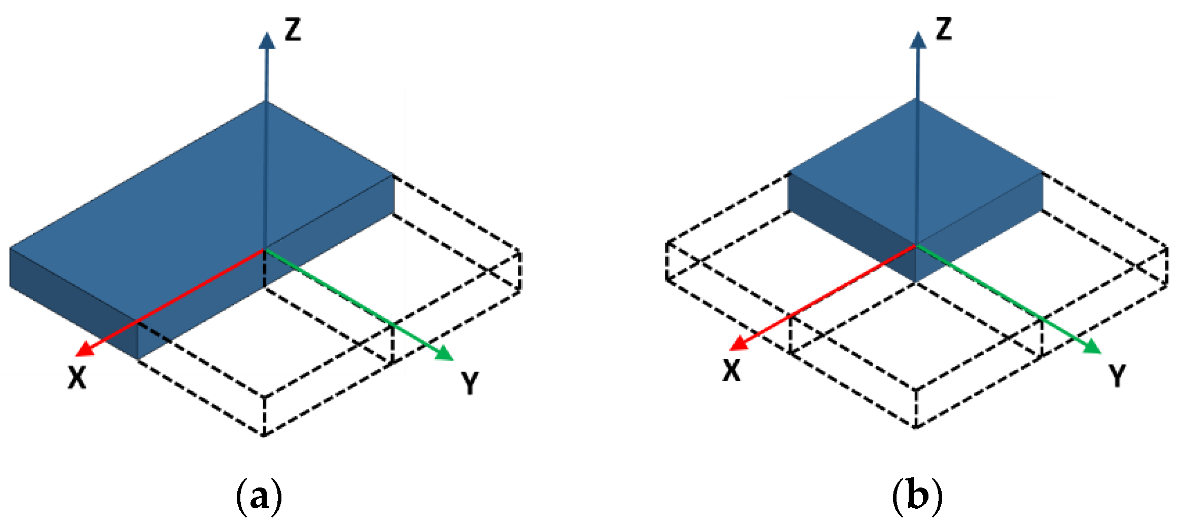
The rectangular shape of a pouch cell makes it suitable for partial modelling. When the model is symmetric about one or more of its own axes, the symmetry boundary conditions can be applied. In this study, the external electronic connections or terminals were not included in the FE model, therefore it was possible to develop a model with one or two symmetric planes. The necessary prerequisite of applying a symmetry boundary condition is to check the normal velocity at symmetry faces. The velocity should be zero as the face is selected in such a way that there is no movement of the nodes across the face.
The symmetry boundary conditions are possible along the XZ-plane and YZ-plane as the compression of the battery cell takes place in the Z-direction. At first, a half model was developed using the homogeneous modelling technique with only one symmetric plane (such as the XZ-Plane as shown in
Figure 9a. To further reduce the number of elements, a quarter model of pouch cell was developed. The new model is symmetric about both the XZ-plane and YZ-plane as shown in
Figure 9b.
5. Results
For the evaluation of simulation results, the structural–mechanical properties of the individual models are presented. In the foreground is the mechanical integrity, the energy balance and the calculation time. For individual models, parameter studies were also performed to evaluate the effect of the contact friction between the ball punch and the battery cell, as well as the failure strain or maximum elongation of the separator at the breaking point. The effect of anisotropy on separator materials is also observed. Finally, the force-displacement curves of the individual modelling methods are compared and discussed.
A total of six models were developed for this study, four representing each modelling technique and two further models representing the partial modelling technique. Output related to energies, contact forces and rigid body displacements were extracted from the simulation.
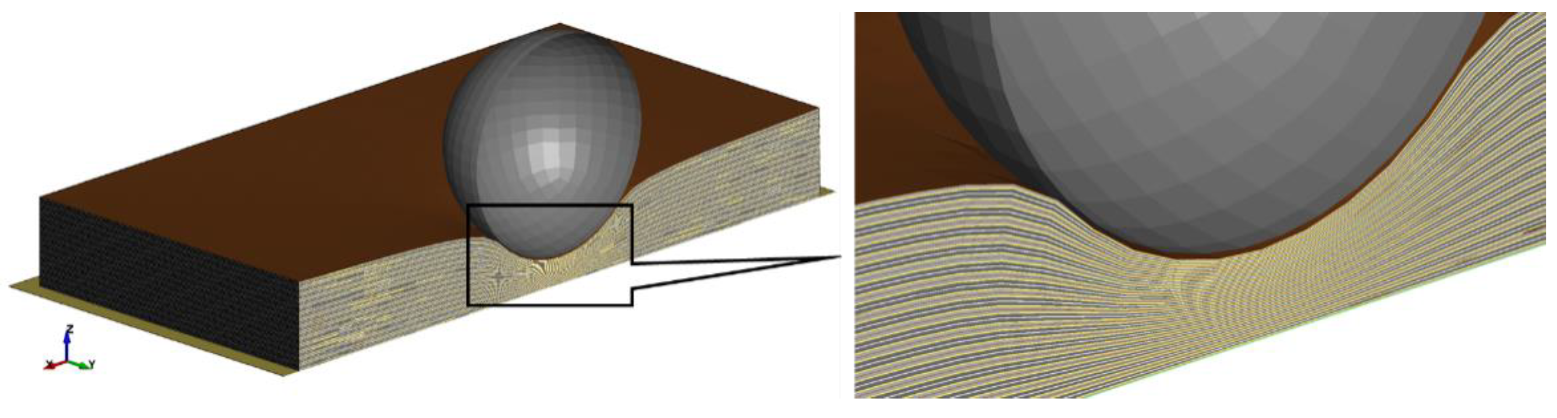
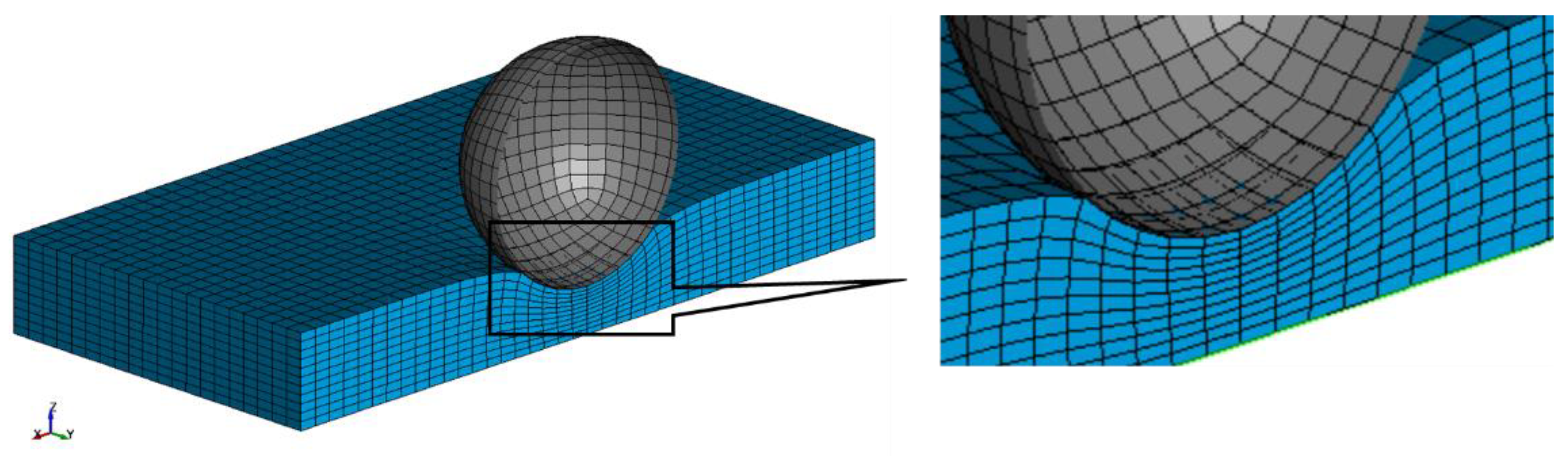
Figure 10 shows the cross section of the deformed battery cell with the heterogeneous modelling technique. All component layers below the spherical indenter are compressed and deformed. With the highly detailed heterogeneous modelling technique, it was possible to predict the behaviour of individual layers and localised deformation for after spherical indentation.
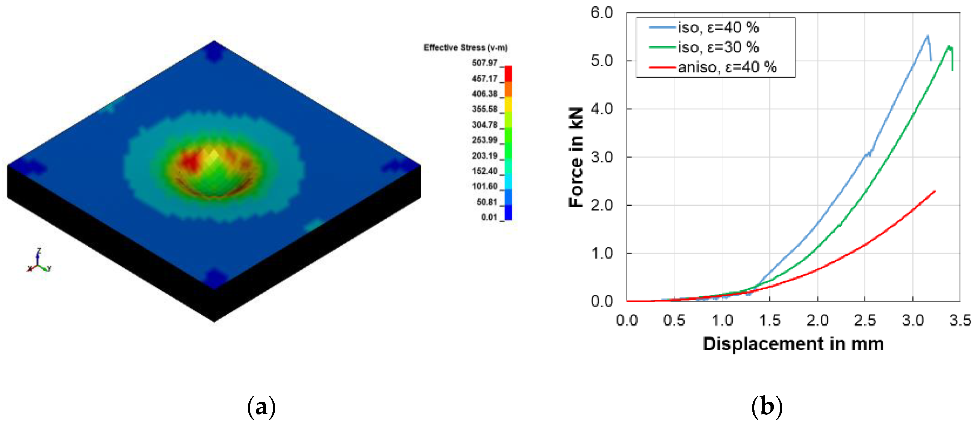
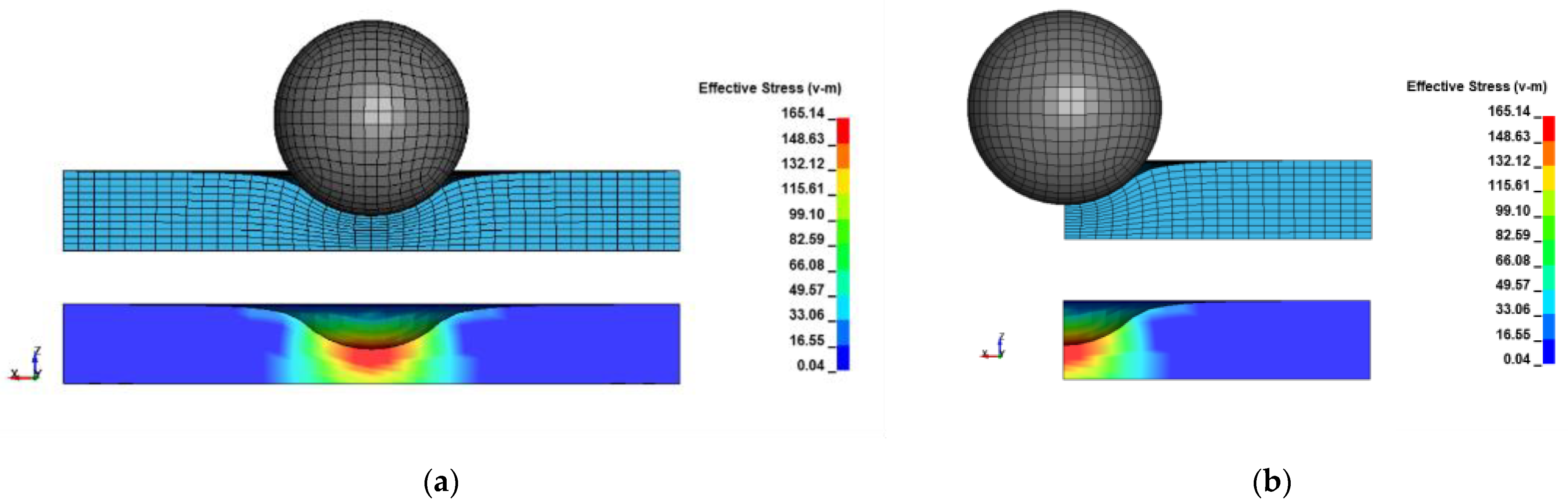
The stress distribution as a result of indentation is displayed in
Figure 11a. The stresses are concentrated in the region where the circumference of the sphere is in contact with the cell. The failure of the battery cell is observed from a sudden drop in the force response of the cell as shown in
Figure 11b. The maximum force of 5516 N was achieved at 3.1 mm of displacement for the isotropic model with 40% failure strain. It took 40 h to compete the simulation on workstation. It can be observed that the response of the model is different when the anisotropy is applied to the separator.
For similar simulation settings i.e., with 40% failure strain, initially there was no drop observed for the anisotropic separator model. The increase in force was also less than that of the isotropic separator model. The simulation was completed in 95 h. To achieve closer behaviour, the failure strain of the separator was reduced by 10%. The newly selected value of the failure strain of 0.3 or 30% is still within the range of values documented in the literature from 0.1 to 0.7 [
12]. The reduction of the failure strain leads to a steeper increase of the force.
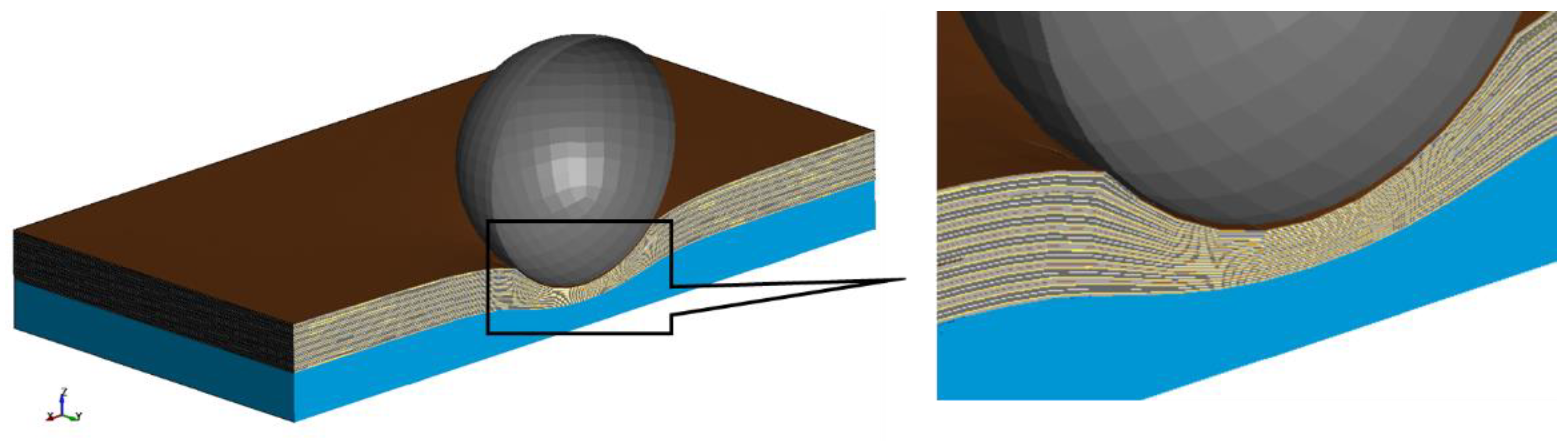
The deformation in the second model with a homogeneous modelling strategy is shown in
Figure 12. When compared to a heterogeneous model simulation, these simulations were very fast—it only took 2 min to complete the simulation with the homogeneous modelling technique.
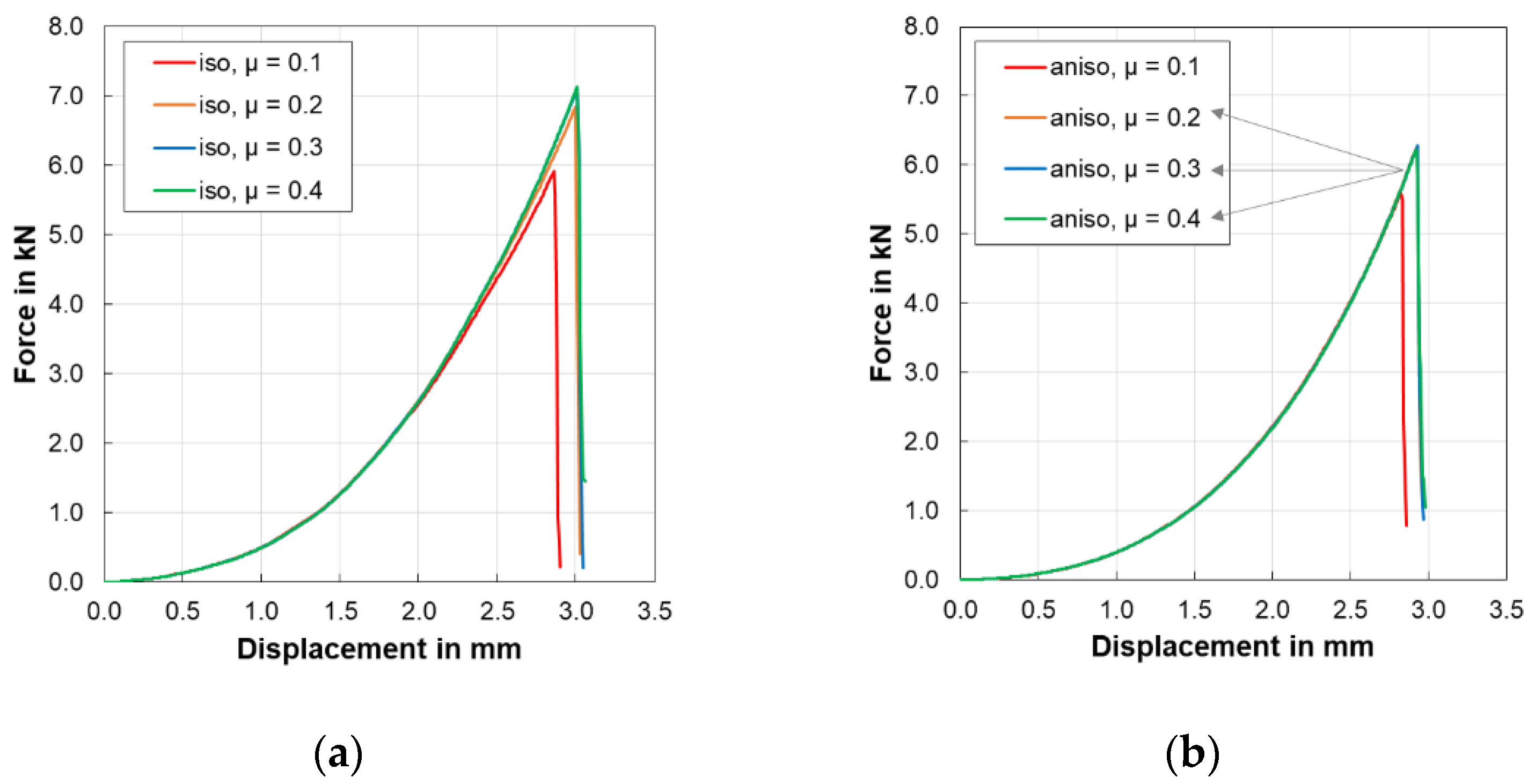
Although the behaviour of individual layers is not visible in this model, it can still indicate the failure of the cell by a drop in force as shown in
Figure 13a. For the isotropic model, the influence of a frictional coefficient on the simulation results was investigated.
An increase in the friction coefficient increases the maximum force and the failure point is also prolonged. Anisotropic models showed a similar trend as shown in
Figure 13b.
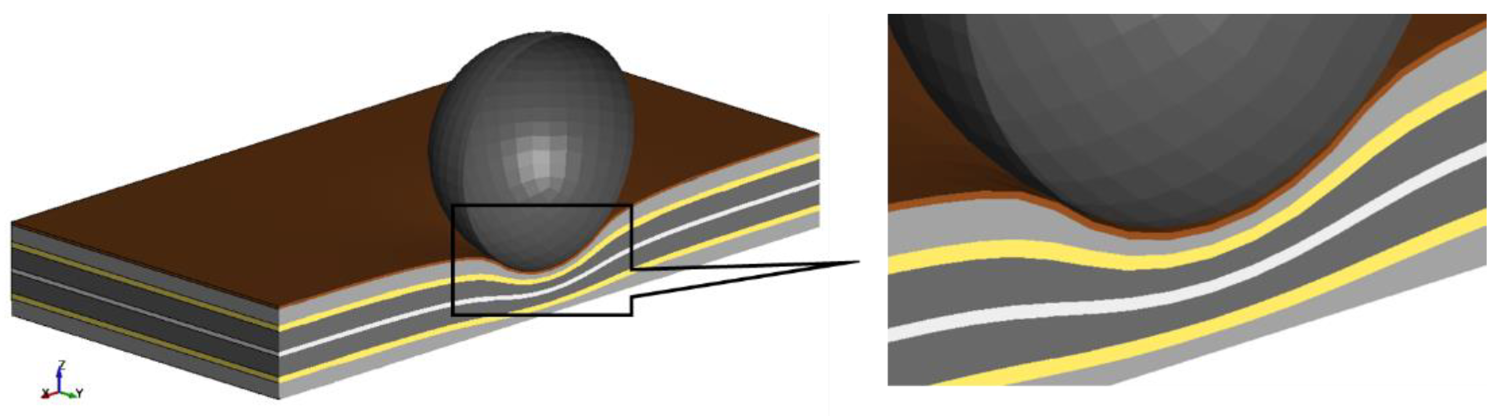
The deformation of the next model with the hybrid modelling method can be seen from
Figure 14. The upper layers just below the sphere were deformed similar to the heterogeneous model. The prediction of behaviour of the individual component layer was possible and the lower homogeneous part behaved similar to the homogeneous model.
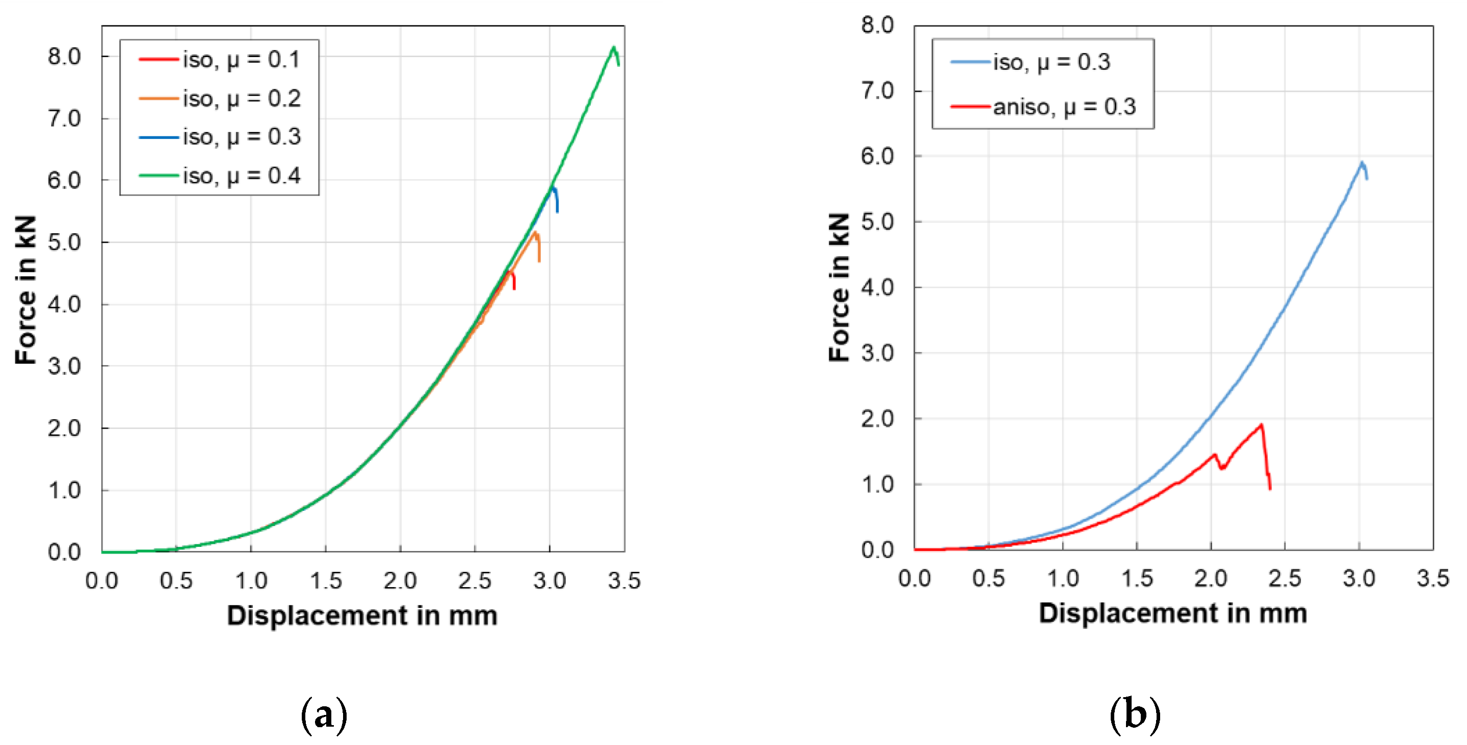
The isotropic model took 17 h to complete the simulation. The force response of the battery is shown in
Figure 15a with a parametric study involving the coefficient of friction between the sphere and battery cell.
It was observed that the coefficient of friction has a considerable effect on the maximum force and the displacement of the indenter at the failure point. An increased coefficient showed an increase in force and delayed the failure. Furthermore, from
Figure 15b it is noted that the model with the anisotropic separator showed a failure with similar simulation settings but a drop in force occurred early with a lower force. The simulation took 25 h to complete.
The fourth model using a sandwich modelling technique also predicted the deformation of the cell as shown in
Figure 16.
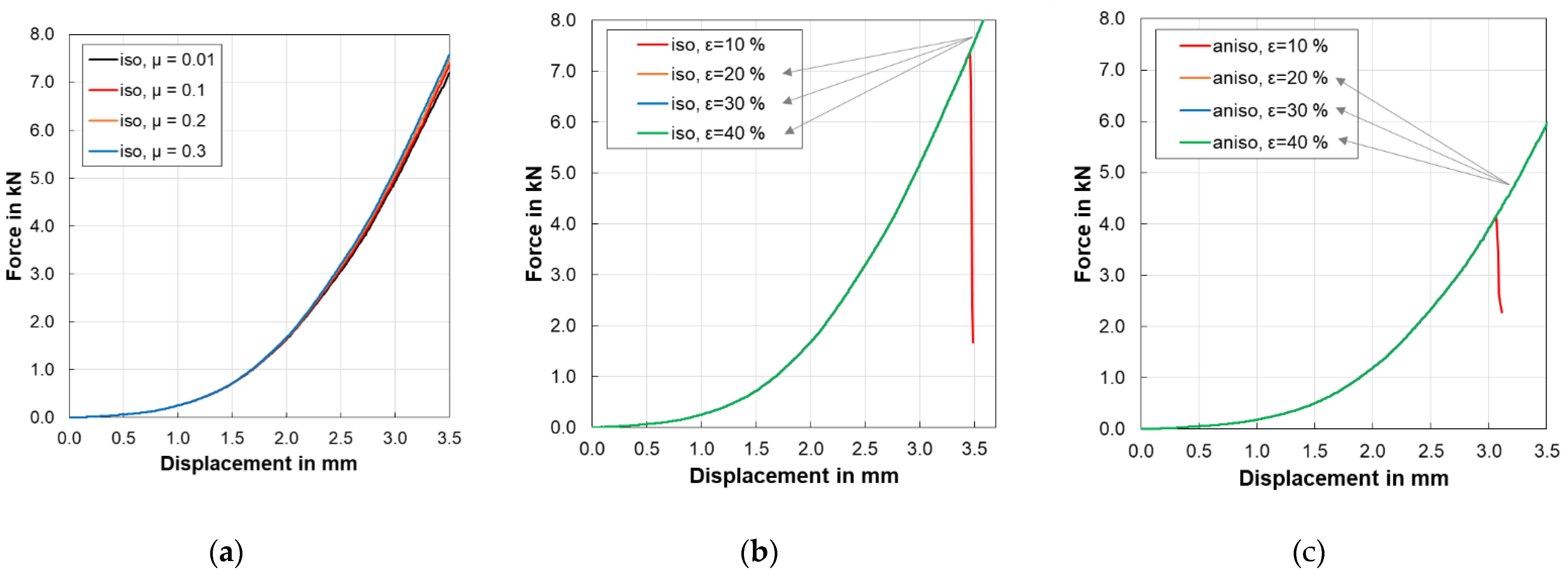
Initially the model did not show any failure or a sudden drop in force. A parametric study was conducted to check the effect of the coefficient of friction on the failure point as shown in
Figure 17a but the drop was not observed within the given simulation time. The simulation lasted 25 min.
To solve this problem, another parametric study was performed with different values of failure strain as shown in
Figure 17b. With this parametric study it can be determined that failure occurs if elongation at break or failure strain for the separator is 10%. The force curve was identical with a different failure strain for the separator. On the other hand, the anisotropic model using a sandwich modelling method demonstrated the failure point with a very low coefficient of friction (0.01) and 10% failure strain as displayed in
Figure 17c. The simulation took over 32 min to complete.
In the partial modelling method, both the half and quarter models predicted the deformation as demonstrated in
Figure 18.
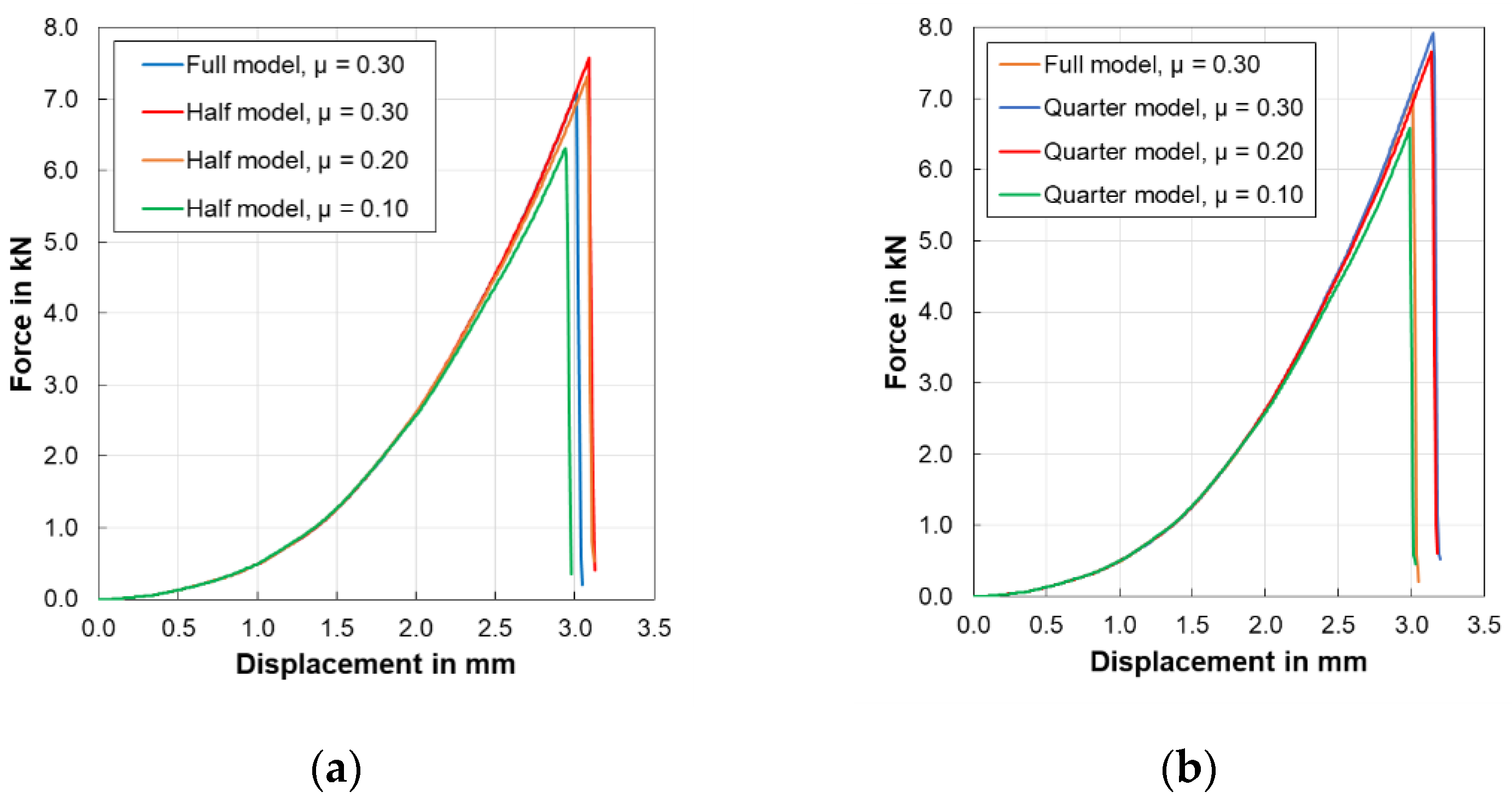
As this method was applied to a homogeneous model in this study, the observations of the individual layers were not possible. However, the force response graphs of both partial models showed failure points.
Figure 19a, b showed parametric studies conducted for both partial models. The figures also show the comparison of models with the full model.
In the case of partial models, it is important to scale the results while interpreting the graphs, because the forces for the full model are twofold larger than that of the half model and four-fold larger than that of quarter model due to cell geometry. However, displacement in the Z-axis remains the same for full, half and quarter models. The simulations of partial models were completed within a few seconds on each workstation.
6. Discussion
Battery modelling for crash safety of the battery has its own challenges. Investigating structural integrity of the cell with finite element methods demands various inputs. The mechanical material properties of the commercial battery cells are not easily available for simulation. For estimating the properties, various tests need to be conducted. Another challenge is the calibration of the model. Experimental data is required to validate the models. With this background, a method of modelling can be considered suitable when all the necessary data for modelling is available. The requirement of the input data is dependent on the modelling method and material card used to depict the behaviour of battery components.
Table 1 shows a summary of all simulations performed in this study.
After evaluating the simulation results of all six models with different strategies, it was found the prediction of battery cell behaviour upon indentation load can be observed with all methods. The indentation with a spherical object could deform the battery cell. Localised deformation has led to failure of the cell in all models. From this summary, it can be seen that the simulation time is dependent on the number of elements. For example, the isotropic model using the heterogeneous method took 40 h to complete the simulation whereas the hybrid model took 17 h to finish. The sandwich model with isotropic material only 25 min and the homogeneous model simulation ended in only 2 min. The partial models using the homogeneous modelling technique took seconds to complete the simulation.
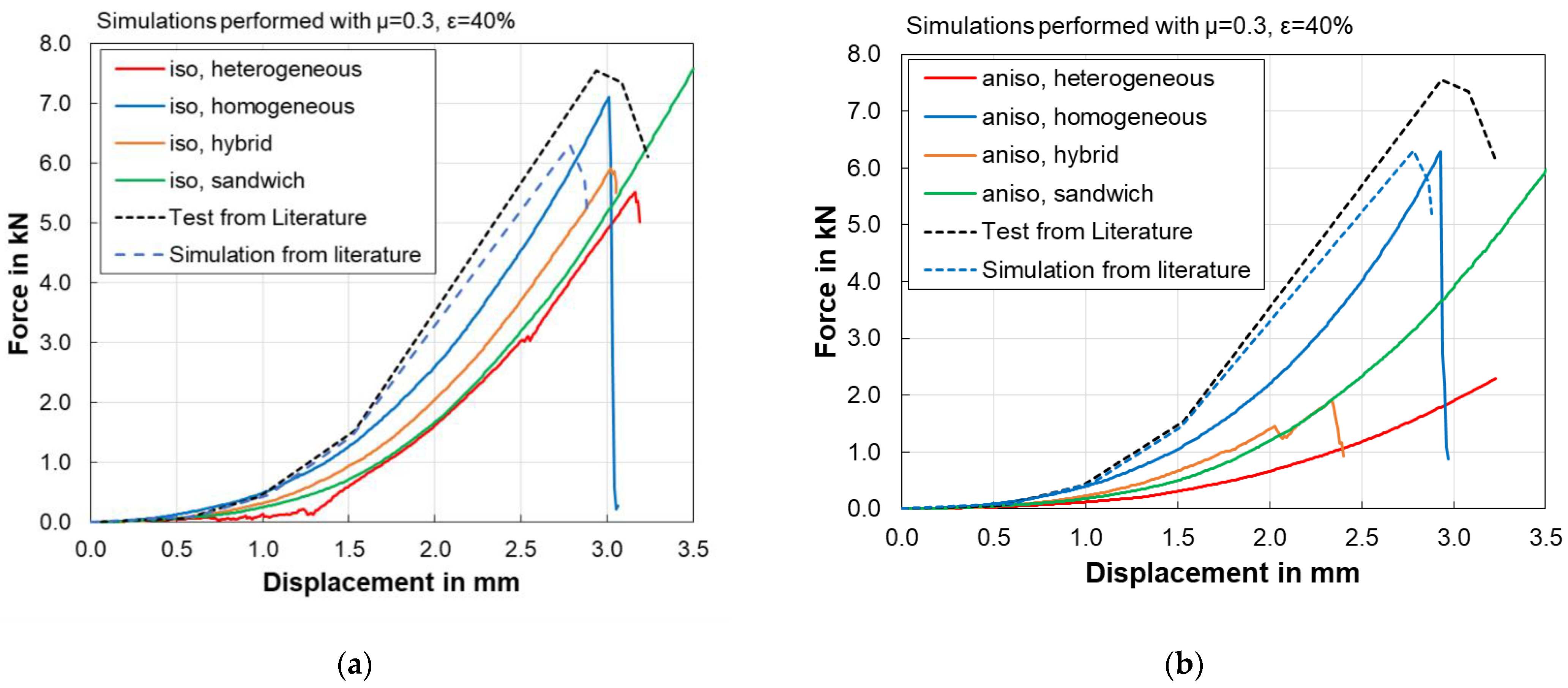
It was observed that the structural failure of each battery cell model is dependent on the coefficient of friction between indenter and battery surface. The failure strain of the separator also influenced the failure point. To compare the model, the coefficient of friction and failure strain for all models are considered 0.3 and 40%, respectively.
Figure 20a,b shows the force-displacement curves of the individual modelling methods with isotropic and anisotropic properties. A test result from Sahraei et al. [
5] is also added for reference.
All isotropic models other than the sandwich model showed cell failure. Homogeneous and hybrid models showed similar failure displacement but different forces at failure. The heterogeneous model showed a failure point but at a later stage and with lower force. A similar trend was observed in the case of anisotropic separator models. The model with more components i.e., the heterogeneous model has low stiffness, and the homogeneous model has more stiffness than all other models.
It should also be noted that the accuracy of the modelling strategies cannot be judged by comparing with test results from literature. This is because the material properties of the cells in the literature differ from the material properties used in this study. Furthermore, the rate dependent properties are not considered in this research. The indenter velocity of the test was selected to be between 0.5 and 3 mm min
−1 [
5] whereas in this study the velocity was set to 1 m s
−1. Lowering the indenter velocity in a simulation results in a substantial increase in simulation time. The current study is performed by referring to the material data from different literature and using the available computational power. Furthermore, the effect of electrolytes is not considered in this study. Sahraei et al. [
18] state that dry pouch cells (without electrolyte) had higher stiffness compared to wet (with electrolyte) pouch cells. The calibration of both simulation models can be done by assigning a specific failure strain value corresponding to drop in force. In the future, for better calibration and validation of the FE Model, a material characterisation test data and spherical indentation test data from the same battery cell should be used.
7. Conclusions
The main aim of this study was to evaluate different modelling strategies used in the investigation of the mechanical integrity of a battery cell using finite element simulations. A sample pouch cell was selected for the modelling. Four battery cell models were created with four modelling techniques including heterogeneous, homogeneous, hybrid and sandwich modelling. Each model was further assigned with isotropic and anisotropic material properties. Furthermore, two partial models were created with symmetry boundary conditions. The spherical indentation test was chosen for simulations. Parametric studies were performed for the identification of influence of simulation settings on results. The force-displacement curves were obtained from all simulation results with identical simulation settings for better assessment. The models were compared with each other in terms of complexity and simulation time. The following conclusions can be drawn from this study.
The finite element models developed with each method predicted the behaviour of the battery cell after indentation with sufficient accuracy and displayed local deformation of the cell near indenter.
The coefficient of friction between the sphere and the cell significantly influenced the force response of the cell. Similarly, the failure strain of the separator also affected the cell failure.
When the models were suitably calibrated by parametric studies, a sudden drop in the force was observed in the force displacement diagram. This drop indicates mechanical failure of the battery cell. Therefore, each method is suitable for prediction of failure of the battery cell.
The anisotropic material properties of the separator can be incorporated in the finite element model with all described modelling techniques. A selection of a suitable material model facilitates the directional behaviour of the separator.
Symmetry boundary conditions allow for the creation of partial models of battery cells and these models can also predict the mechanical failure when they are suitably calibrated.
The number of elements in the model and number of contact interfaces had a huge impact on computational time as well stiffness of the model.
Accuracy of the modelling method could not be predicted only on the basis of its complexity or realistic construction. It also depends on the selection of a suitable material card and appropriate input parameters.
Based on the current results, the models using a homogeneous modelling technique are time efficient and therefore this method is applied in our current research projects. For optimisation of the exiting models, further parametrisation of the models is required. Higher computational capacity could help to maintaining reasonable simulation time. Furthermore, the accuracy of these models can be evaluated by validation of the simulation models. Experiments could be performed with the same pouch cell dimensions and material. Additionally, it is possible to extend the heterogeneous and sandwich model by adding electrical components. Mechanical, electrical and electrochemical coupling could allow for short circuits and the subsequent temperature increase, and thermal runaway could be simulated. The effects of temperature-dependent material such as softening could be taken into account in upcoming studies. The simulations in this study were quasi-static and another approach using dynamic simulations could also bring more variables into the selection process of the modelling approach. There is huge potential in the field of battery simulation and substantial area is yet to be explored and could be a topic for future studies.


