Article

Numerical Modeling and Safety Design for Lithium-Ion Vehicle Battery Modules Subject to Crush Loading

1
Hopkins Extreme Materials Institute (HEMI), Johns Hopkins University, 3400 N. Charles Street, Baltimore, MD 21218, USA
2
Department of Mechanical Engineering, Johns Hopkins University, 3400 N. Charles Street, Baltimore, MD 21218, USA
3
Department of Aerospace Engineering, Embry-Riddle Aeronautical University, 1 Aerospace Blvd, Daytona Beach, FL 32114, USA
*
Author to whom correspondence should be addressed.
Energies 2021, 14(1), 118; https://doi.org/10.3390/en14010118
Submission received: 21 November 2020 / Revised: 11 December 2020 / Accepted: 23 December 2020 / Published: 28 December 2020
(This article belongs to the Special Issue Crash Safety of Lithium-Ion Batteries)

Abstract

:
In this work, a computational study was carried out to simulate crushing tests on lithium-ion vehicle battery modules. The tests were performed on commercial battery modules subject to wedge cutting at low speeds. Based on loading and boundary conditions in the tests, finite element (FE) models were developed using explicit FEA code LS-DYNA. The model predictions demonstrated a good agreement in terms of structural failure modes and force–displacement responses at both cell and module levels. The model was extended to study additional loading conditions such as indentation by a cylinder and a rectangular block. The effect of other module components such as the cover and cooling plates was analyzed, and the results have the potential for improving battery module safety design. Based on the detailed FE model, to reduce its computational cost, a simplified model was developed by representing the battery module with a homogeneous material law. Then, all three scenarios were simulated, and the results show that this simplified model can reasonably predict the short circuit initiation of the battery module.

1. Introduction

Lithium-ion battery (LIB) systems have been widely used as the main power source in new generation hybrid and electric vehicles [1]. However, the safety of these new vehicle systems in the field has become a primary issue [2,3]. On an electric vehicle (EV), the battery system sustains various types of mechanical loadings due to road–vehicle interactions and possible harmful collisions from traffic accidents. The recent rise in the number of field incidents associated with commercial vehicle battery systems has led investigators and safety engineers to study the mechanical integrity of the LIB under abuse conditions. Dangerous consequences and threats to EV safety include capacity or properties fading, short-circuit induced thermal runway, fire or explosions, structural integrity issues, and others. Consequently, a better understanding of the crushing and failure behavior of vehicle battery systems has drawn widespread attention from government agencies and engineering communities. Sufficient knowledge in this important field is necessary to develop effective and efficient countermeasures to improve electric vehicle safety.
Extensive experimental and computational studies have been conducted to investigate the structural failure and voltage change of LIB systems (including cylindrical, pouch, and prismatic cells) under abuse conditions [2,3,4,5]. Typical loading conditions for the mechanical abuse tests were nail penetration, punch indentation, in-plane and out-of-plane compression, plane strain, three-point bending, etc. The force response and voltage change were measured and correlated to investigate battery structural failure and short circuit behavior under these conditions. The effect of state of charge (SOC) and loading rate was also considered. On the modeling side, there are several different strategies: (1) detailed models, which have the most information about a real battery cell but are computationally intensive, (2) homogenized models, which are computationally efficient, but cannot describe the detailed failure mechanisms; and (3) the representative volume elements (RVE) approach which is intermediate to these two strategies.
However, most studies focus on the battery cells, and relevant research on entire battery modules is still very limited. The interaction between the battery cells and other parts of the module (e.g., frames, covers, cooling plates, connectors, etc.), subject to various loadings, on the failure behavior of cells is complex and not fully understood, even though this is more realistic for in-service conditions. Therefore, it is imperative to conduct module-level or larger-scale tests and simulations. A better understanding of the structural response of battery modules would be helpful to improve the design of the battery packs and possibly provide protective countermeasures. To date, noticeably fewer studies on battery modules have been reported in the open literature compared to research at the battery cell level. For example, Lai et al. [6] conducted a combined experimental and computational study on a module under in-plane constrained compression. They focused on a small part of the module, i.e., a representative volume element (RVE). Kalnaus et al. [7] analyzed the effect of cooling plates on the mechanical response of pouch battery cell stacks. The results showed that the presence of cooling plates reduces the out-of-plane indentation force by approximately a factor of 1.5 and thus reduces the energy absorption before the short circuit. Xia et al. [8] reported a numerical simulation on the damage behavior of a battery pack with cylindrical cells due to ground impact, including a detailed analysis of the failure mechanisms. In a separate study by Xia et al. [9], a series of impact tests were performed on a pouch cell module using a drop tower with various combinations of loading speed, direction, drop mass, and shape of the impactor. The mechanical, electrical, and thermal responses of the modules under various loading conditions were analyzed. It was found that impact along the battery cell thickness direction was quite dangerous. Due to the increasing compaction during the impact, the battery cells failed severely, and the heat generated was not released effectively, causing thermal runaway in the form of fire and smoke. In their subsequent studies, they studied the interaction between pouch cells within the module [10] and compared several different structural designs of cooling plates to improve the battery module crashworthiness [11].
A recent experimental study was conducted to investigate the global and local structural failure of a commercial vehicle battery module with pouch cells under different loading scenarios [12]. Based on these tests, numerical models were developed in this current study to achieve four main goals: (1) simulate the module damage response under various crush loading conditions; (2) analyze energy absorption behavior under these conditions; (3) investigate the effect of other module components such as cover and cooling plates; and (4) simplify the module model so it can be easily integrated with the vehicle model at low computational cost with little loss of accuracy.

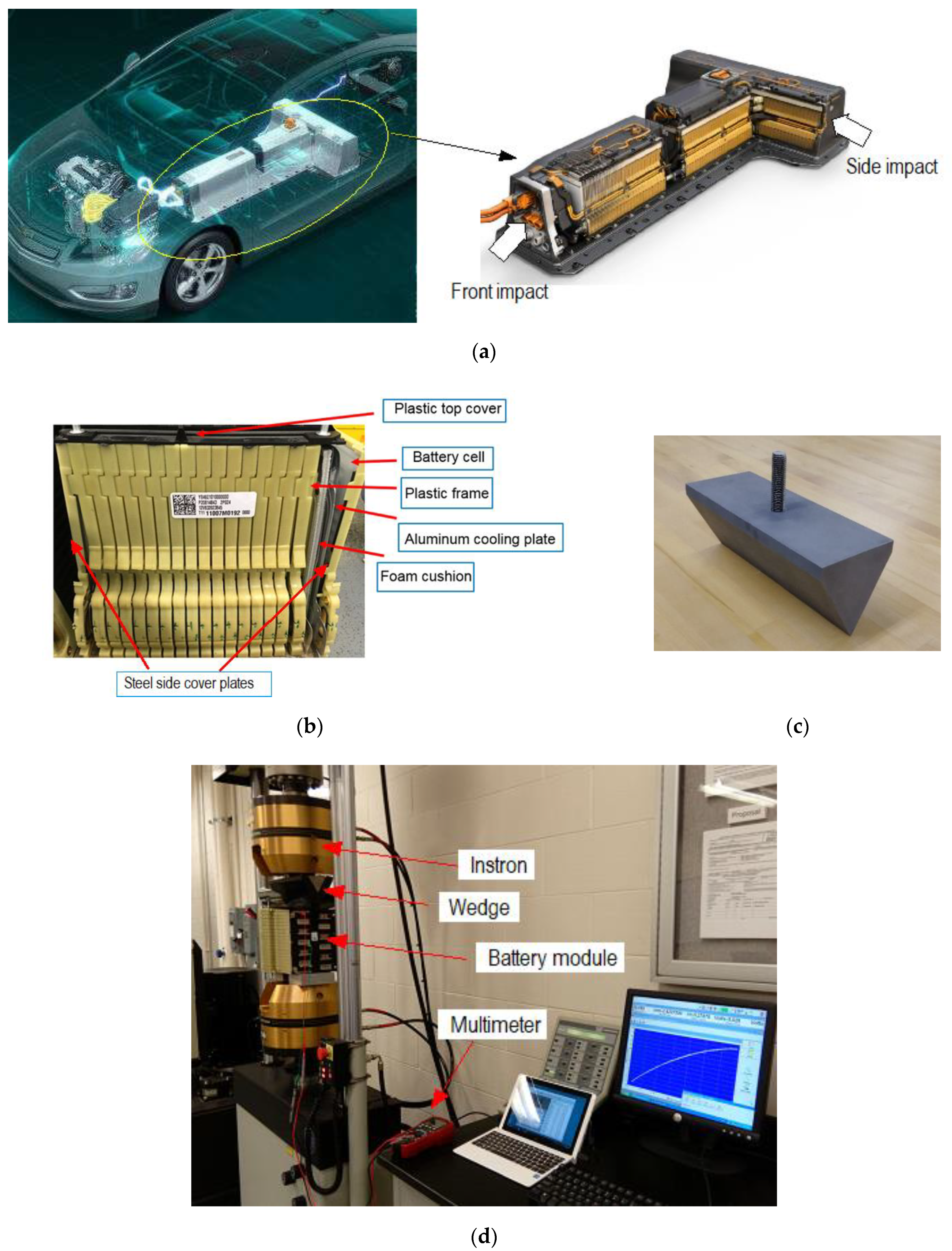
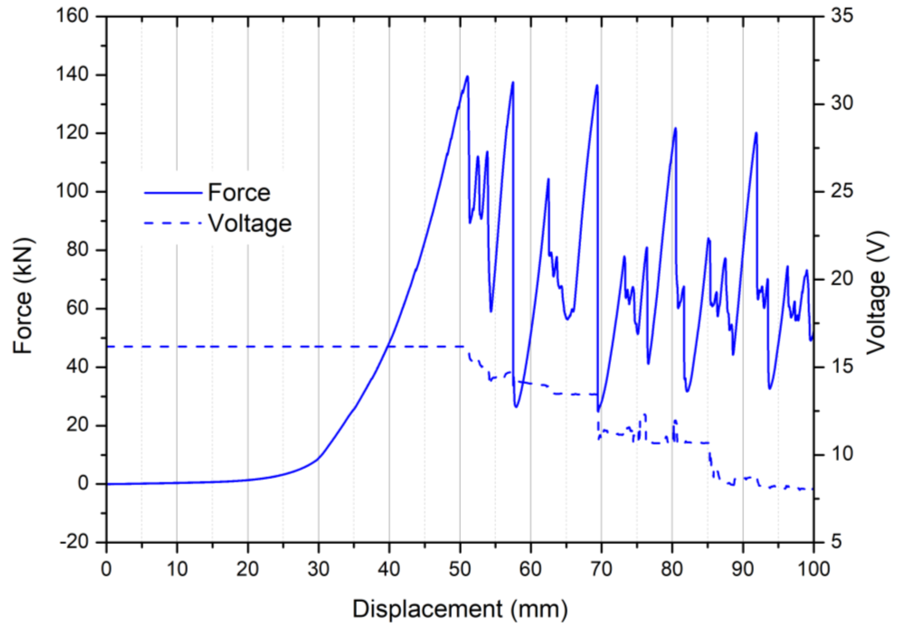
2. Battery Module and Wedge Indentation Tests

Experimental quasi-static and low speed crushing indentation tests were performed on a commercial battery module (LG Chem, Seoul, Korea) used on a hybrid vehicle Chevrolet Volt with a rigid wedge to investigate module level structural damage under large deformation and fracture. On the vehicle, over 200 Li-ion pouch cells form nine battery modules in a “T”-shape pack located under the rear seat and in a tunnel between the front seats, as shown in Figure 1a. Therefore, when undergoing front or side impact, the pouch cells would be subject to loadings along the thickness direction.
The module configuration is shown in Figure 1b. The total mass of the module is approximately 20 kg. Each module consists of a high stiffness plastic panel where the electrodes are mounted and 18 yellow plastic frames stacked in the thickness direction. Within each frame, two Li-ion pouch cells are connected and separated by a polymeric cushion layer sandwiched between two aluminum alloy cooling plates. So, each module consists of 36 pouch cells. At each end of the module, a corrugated steel cover plate is used for shock load mitigation and protection.
Severe thermal runaway at high SOC during structural damage can be dangerous. Prior to testing, pouch cells were discharged to a low physical SOC (close to zero) using a resistive heating element. Since the average voltage for fully charged modules is around 40 V, a reasonably low SOC level was achieved by discharging to a range of 10–20 V. The presence of any voltage, even at very low physical SOC, can be used to help monitor the damage effect of mechanical loading on short circuiting. During testing, this is observed as a sudden drop of voltage, provided at least some energy/voltage remains. A stainless steel triangular shaped 60° wedge was used for indentation, as shown in Figure 1c. The wedge was fabricated by CNC machining and tapped to accept a 4 in (101.6 mm) long, 3/4 i-10 TPI threaded stainless steel rod as needed for hydraulic gripping. The wedge had 18.0 kg mass, was 4.5 inches (114.3 mm) wide by 4.5 inches (114.3 mm) tall, and 12 inches (304.8 mm) long. To decrease room light reflections for observation and photography, the wedge was ambient air grit blasted at 85 psi (5.86 bar) with Central Pneumatic Glass Bead 80 Grit Abrasive Media (Harbor Freight Tools, Camarillo, CA, USA). To prevent short circuit, a thin rubber sheet was placed between the steel wedge and battery modules prior to testing. An Instron (Norwood, MA, USA) servo hydraulic test system (model 8802) with 250 kN capacity was used to apply load, as shown in Figure 1d. During testing, module components were held aligned using long threaded galvanized steel rods and galvanized nuts through the plastic frames. Modules were supported by thick aluminum alloy plates. The load was applied through the module thickness, since this is the most dangerous front or side impact direction [9].
The actuator was set to move over the near-maximum actuator displacement distance of 100 mm at 0.06–50 mm/s respectively. Preliminary tests revealed that 50 mm/s was near the maximum rate for the Instron 8802 system. Considering the real-world crash scenarios, the vehicle structure deforms significantly and dissipates a large amount of kinetic energy before the battery module starts to deform. The loading rate of the battery is much lower than the crash speed. Therefore, the low-speed crush test data are still informative in the battery failure analysis. The test system load cell and actuator displacement were used for force and displacement measurement. Instron Fast Track 8800 data acquisition with DAX V9.1 software were used for digital data recording. A Dawson (Diamond Bar, CA, USA) DDM230B multi-meter at a sampling frequency of 3 Hz was used to measure voltage during loading for the quasi-static tests (0.06 mm/s). A Tektronix (Beaverton, OR, USA) TDS 1012C-EDU digital storage oscilloscope at a sampling frequency of 1 kHz was used for the higher speed tests (50 mm/s). Voltage was measured between the battery cell on the top layer and another layer in the lower portion of the module, which did not substantially deform during testing, as shown in Figure 1d.
A typical force–displacement–voltage curve for the module undergoing wedge indentation is shown in Figure 2, where multiple peaks can be observed on the force–displacement response. During the early stage of indentation, the whole battery module is compressed, and the cover plate undergoes large plastic bending along with the first two layers of plastic frames. After the first peak force of about 140 kN, the first pouch cell fracture takes place, which is followed by the failure of the second cell and the third one, which is indicated by another two peaks. Later, damage to the other layers is completely caused by wedge cutting. Figure 2 also shows that the voltage drops in a stepwise manner, which indicates the short circuit of pouch cells. The first voltage drop corresponds to the displacement where the first force peak occurs, which is a critical point indicating the initiation of battery failure.

3. Numerical Model Development and Validation

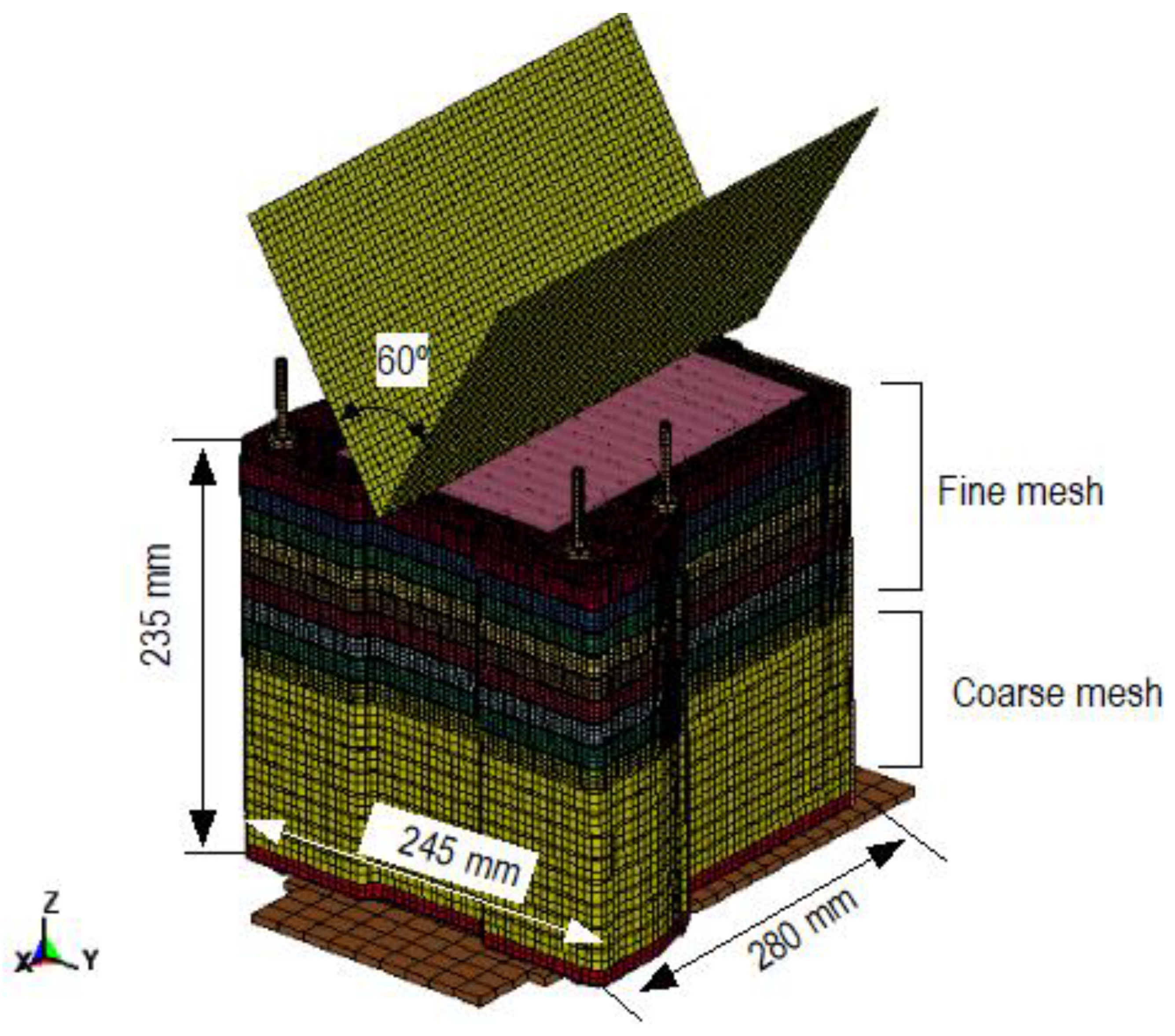
3.1. CAD Modeling and Mesh Development

Based on the battery module component’s dimensions, their geometric/CAD models were created using CATIA V5 (Dassault Systèmes, Vélizy-Villacoublay, France) CAD software. The models were saved in IGES format for subsequent meshing. Then, the CAD models were converted to their finite element model using Altair (Troy, MI, USA) HyperMesh meshing software.
Next, the FE model of each component was assembled to form the FE model for the whole module, which is illustrated in Figure 3, with dimensions. The battery module was modeled with an eight-node solid element. The mesh size for different regions was determined according to the actual loading conditions. For the wedge indentation tests, the maximum displacement of the wedge was 100 mm. Therefore, only the upper part of the module was loaded by the wedge and damaged. In the mesh development, the region with deformation and damage was modeled with a fine mesh, with an average element size of 1 mm. The unformed zone (i.e., the lower part of the module) was modeled using a larger mesh size of 5 mm to reduce simulation time. The total number of elements for the whole battery module model was 274,322. The wedge was assumed to be rigid and modeled with shell elements. A summary of each module component is shown in Table 1.

3.2. Material Modeling

In this study, all simulations were performed using explicit FEA software LS-DYNA V971 (Livermore Software Technology Corp., Livermore, CA, USA). It should be emphasized that the main focus of this research is the failure mechanism of battery modules as influenced by variations of indenter shape and module components rather than the development of new modeling methods or tools. Therefore, the commonly used commercial simulation software and existing material laws were employed. This can also ensure that the results can be reproduced by others.
For these battery modules, there are mainly three types of materials: metals (steel cover plates and bolts as well as aluminum alloy cooling plates), polymers (plastic frames and panel), and Li-ion pouch cells. Their constitutive models are described here. Metallic and plastic parts were modeled using material law 24 (*MAT_PIECEWISE_LINEAR_ PLASTICITY) which is an elastoplastic constitutive relation, where the flow stress σ can be written as a function of effective plastic strain εeff in the form of
σ = σY(1 + Etanεeff)
where σY and Etan are the yield strength and tangent modulus of the material, respectively. In the numerical model, the following material constants were used for Young’s modulus, Poisson’s ratio, and yield strength as well as the tangent modulus. For steel, E = 278 GPa, ν = 0.30, σY = 800 MPa, and Etan = 10 GPa. For aluminum alloy, E = 70 GPa, ν = 0.33, σY = 200 MPa, and Etan = 2 GPa. For plastics, E = 10 GPa, ν = 0.40, σY =80 MPa, and Etan = 150 MPa. Strain rate-dependent behavior was not considered here, because no dynamic effect was observed at the current strain rates.
The pouch cell was treated as a homogeneous solid material without modeling the detailed interior structures, since the present work is not intended to simulate the failure of each individual cell component (cathode, anode, and separator). In this way, the basic trend of the structural response and material failure can be captured at a lower computational cost. As a widely used constitutive law for porous media such as Li-ion battery jellyroll [13,14,15,16], the material type 63 (*MAT_CRUSHABLE_FOAM) in LS-DYNA was used. This material model describes foam behavior through the input of a stress–volumetric strain curve [17]. The foam behavior is assumed to be isotropic, and it is crushed in one dimension with a very small Poisson’s ratio. The stresses are transformed into the principal stress space where the yielding function is defined. The yielding behavior is governed by the largest principal stress. The principal stresses (σ1, σ2, and σ3) are compared with the yield stress Yc in compression and Yt in tension. If the actual stress component is compressive, then the stress is calculated based on a given volumetric strain-hardening function,
Yc = Yc0 + H(εv)
where Yc0 is the stress of foam at the initial yielding point. On the contrary, if the principal stress component is tensile, the stress is set equal to a constant tensile cutoff stress,
Yt = Yt0.
Therefore, the hardening behavior in tension is similar to that of an elastic, perfectly plastic material. The stress–strain curve for the battery pouch of this type was obtained from uniaxial compression tests [18].

3.3. Model Validation

The battery module FE models developed in the previous chapters were validated at the cell level first and then at the module level, which is detailed in Section 3.3.1 and Section 3.3.2, respectively.

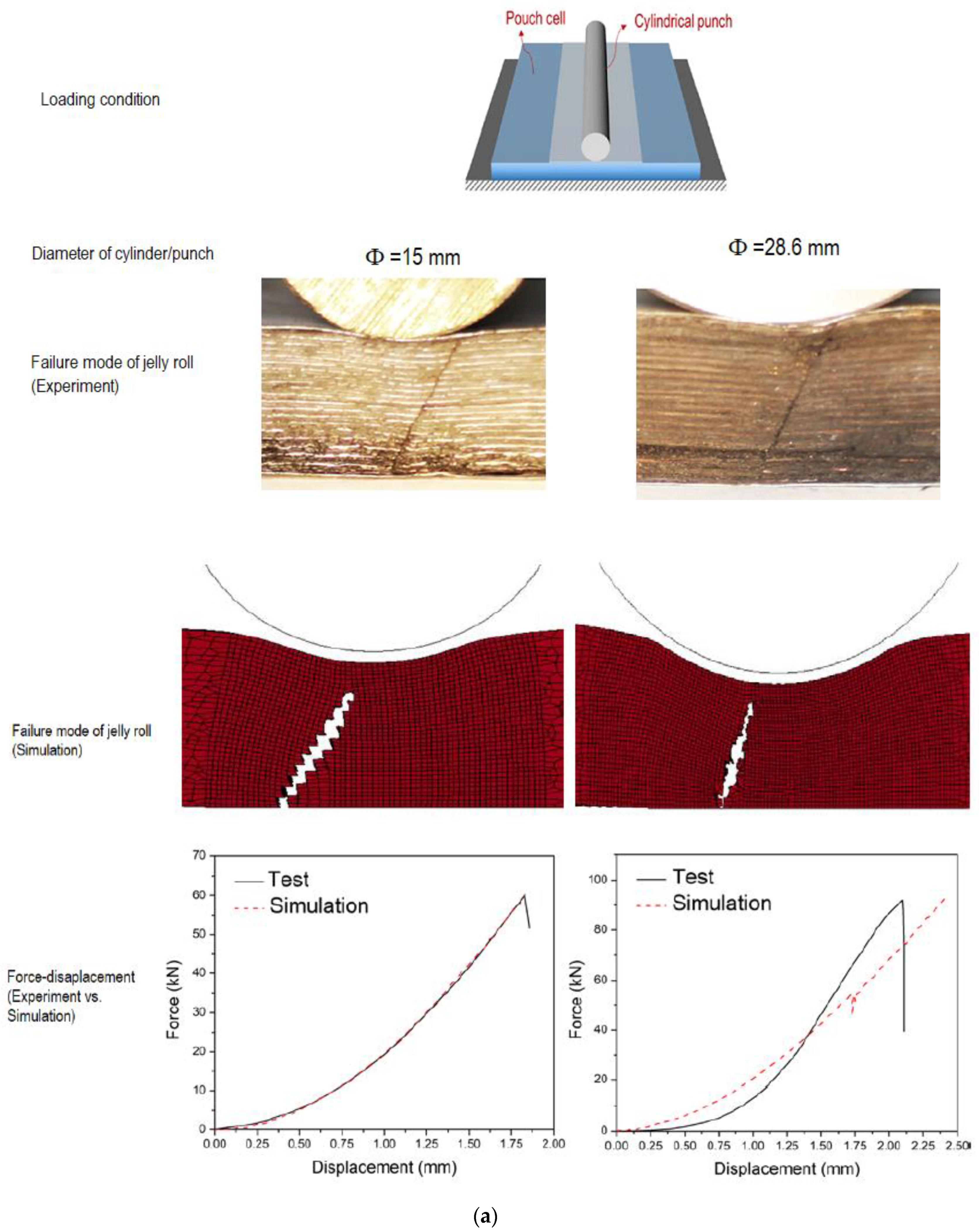
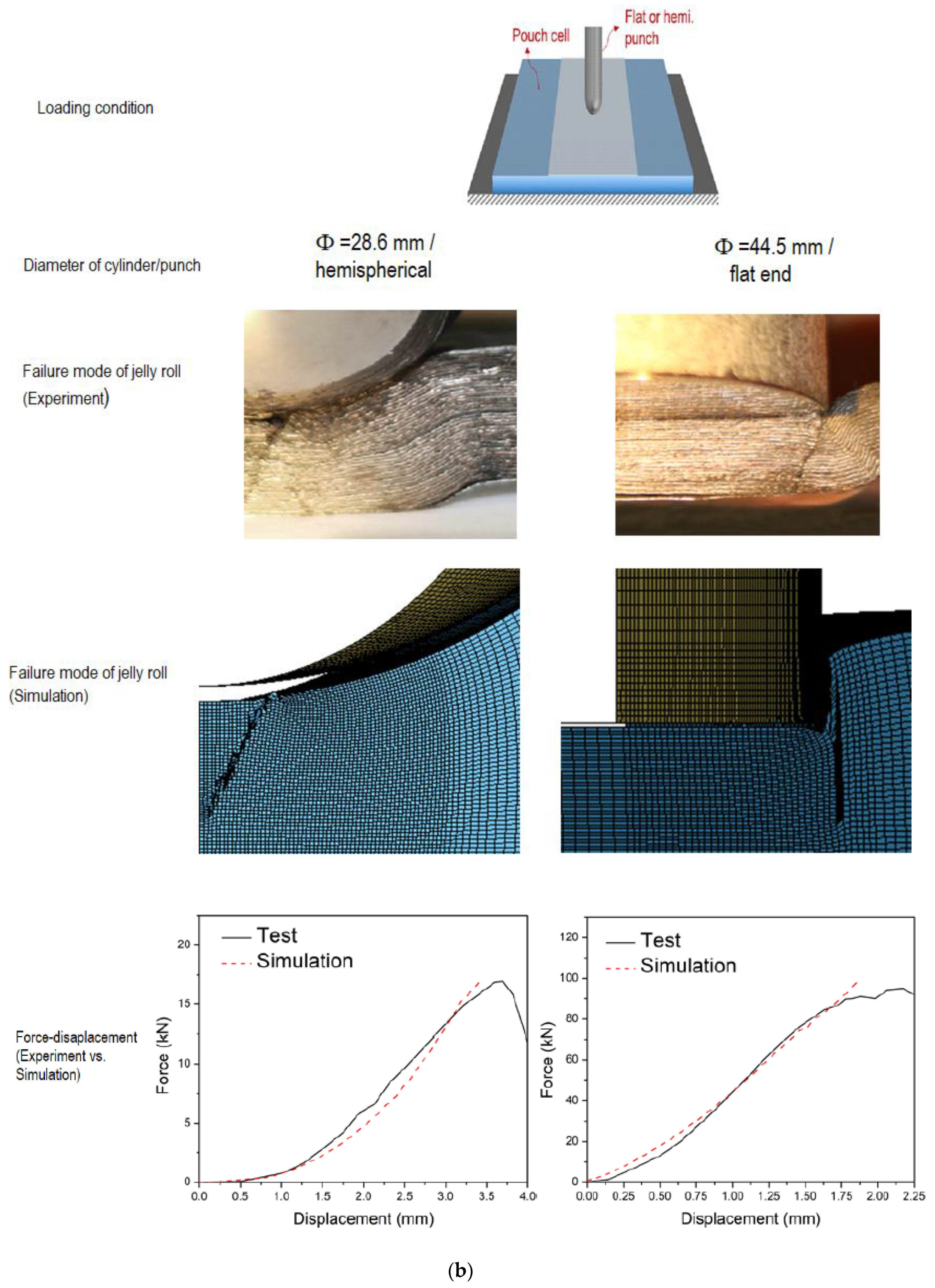
3.3.1. Cell level Validation

Before simulating the module structural response under wedge cutting, the Li-ion pouch cell model was validated by simulating several typical loading scenarios seen in [19]. Here, four quasi-static tests were simulated, namely (1) plane strain with a 15 mm-diameter cylinder; (2) plane strain with a 28.6 mm-diameter cylinder; (3) indentation with a 28.6 mm-diameter hemispherical punch; and (4) indentation with a 44.5 mm-diameter flat end punch. Since the structural deformation under these loading conditions was highly localized, only a small area of the pouch cell was modeled. The cylinders/punches and foundation support were assumed to be rigid and represented with thin shell elements. A mesh size sensitivity study was conducted, and the result showed that an element size of 0.2 mm in the central area subjected to direct loading could produce a convergent result. The element size in the zone close to the boundary without large deformation was much larger to reduce computational time. The simulations were terminated when the force curves started to drop. The model predicted force–displacement curves and failure modes of the Li-ion jelly roll are shown in Figure 4, which are compared with test results reported in [19]. The comparison showed that the numerical model slightly overpredicted the peak force by 0.67%, 0.44%, and 3.37% in the scenarios of (1), (2), and (4), respectively. In case (3), the peak force was slightly underpredicted by 1.16%. The pouch cell models exhibited very similar failure patterns (including the crack locations and directions) with the specimens after tests under all the four loading conditions. A reasonable agreement in terms of both damage model and force response verifies the good performance of the battery cell model.

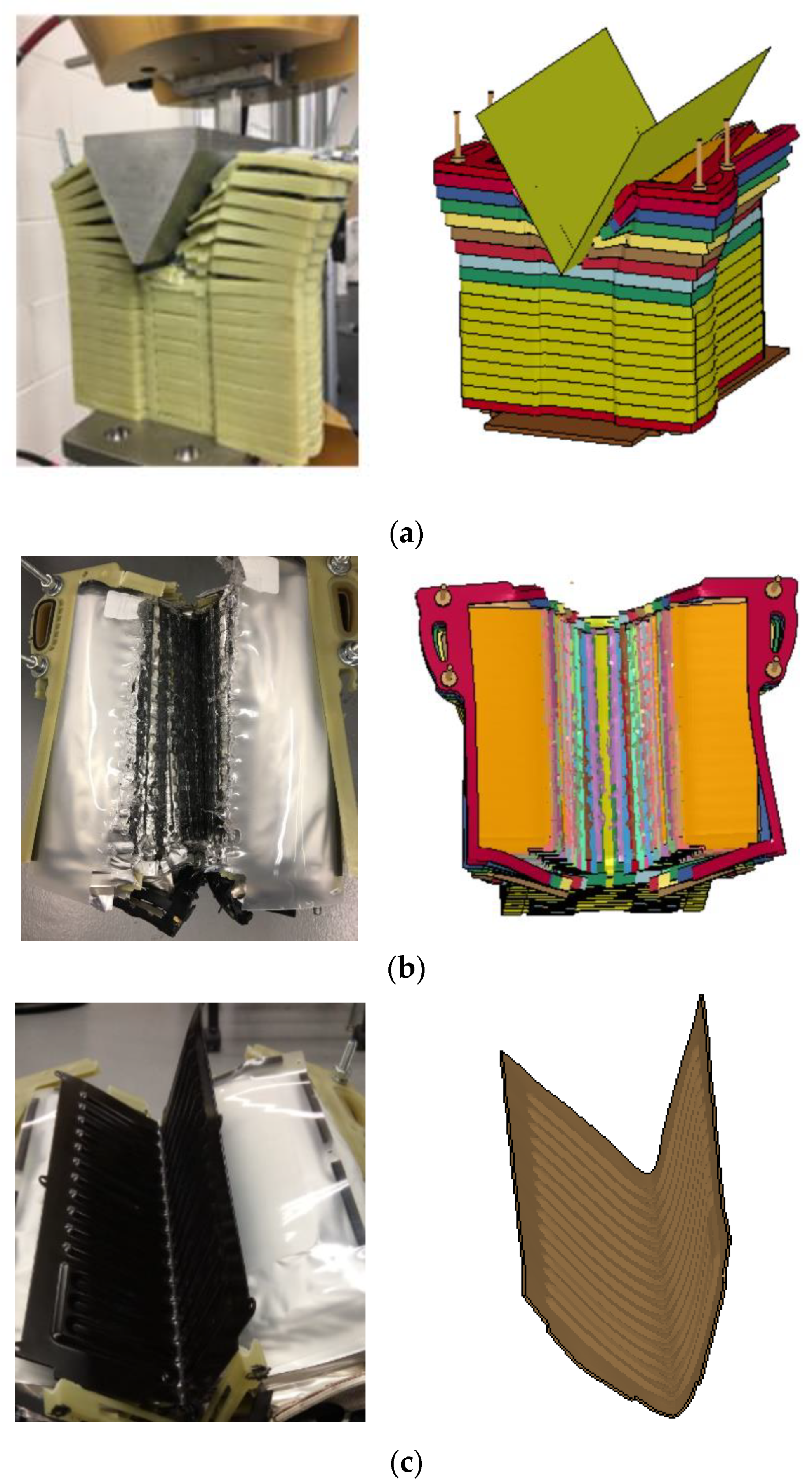
3.3.2. Module Level Validation

Wedge indentation simulations were conducted based on the experimental setup. The model predicted failure models of the battery module are compared with the specimen after the test in Figure 5a (side view), 5b (top view without steel cover plate), and 5c (steel cover plate only), respectively. It is noted that the corrugated steel cover plate was detached from the plastic frame, bent into a V shape, and pushed inside the module, but no fracture took place. A reasonable agreement between test and simulation can be observed.
Quantitative comparisons were made on the force–displacement curve shown in Figure 2. The result can be seen in Figure 6, where six critical points on the curve are marked as (1) through (6). The experimental curve was shifted to ensure that the force starts to rise at zero displacement (where the load actually begins to increase as opposed to the reported actuator position). It can be observed that the simulation and test results are similar in terms of curve pattern and the number, location, and magnitude of peak forces. The model predicted peak force is 150 kN, which over predicts the experimental result by about 7%. The numerical simulation shows that in the early stage of increasing force before the critical point (1), the module is compressed and bent by the wedge, and no material or structural failure takes place. At (1), the first two plastic frames break, but the battery cells are still intact. When the force reaches the first peak at (2), the first Li-ion cell is fully compacted and then breaks suddenly. As a consequence, both force and voltage start to drop, which indicates the initiation of a short circuit. When the second cell is compacted and cut, the second peak drop appears, which causes another voltage drop at (3). This process repeats one more time at (4), where the third cell fractures while force and voltage drop again. Both the experimental observations and simulation confirm that the failure mechanism of the cover plate and the first three cells are a combination of bending and cutting. Damage to the lower layers has a completely different mechanism. Due to the constraint of already compacted bottom layers, their fracture is caused by wedge cutting only. At (5), The fourth and fifth cell break at almost the same time, and (6) is the displacement for the fracture of the sixth and seventh cell. However, the voltage drop does not show a clear correlation with the force peaks in the later stage, and some oscillations can be observed. Since several layers have been completely damaged, the small metallic components in these broken parts may have a complex interaction with the cells in the next layers, and this could make the short circuit behavior more complex and unpredictable, which is unique to details of each situation. A further examination of the force curve indicates that the distance between two adjacent lower peaks Δd is approximately 12 mm, which is the thickness of each plastic frame. Therefore, these lower peaks can be considered due to the fracture of frames. Based on the above comparison and analysis, a reasonable agreement between the model prediction and test data verifies the good performance of the battery module numerical model.

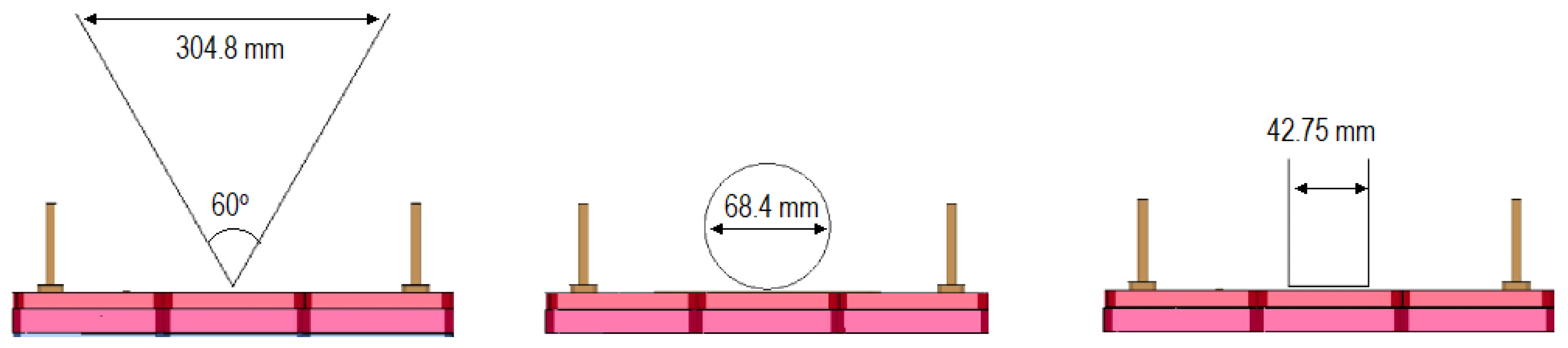
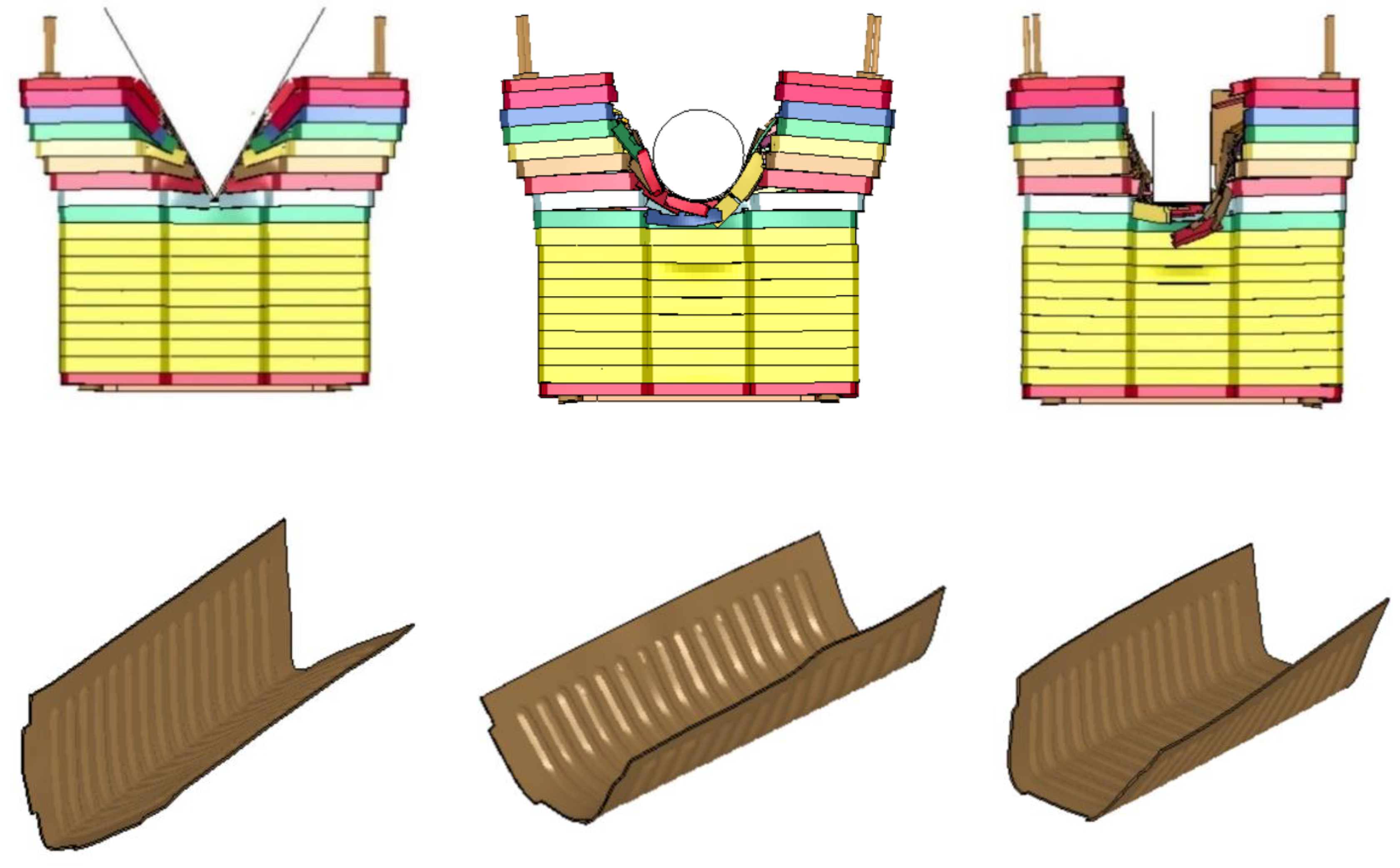
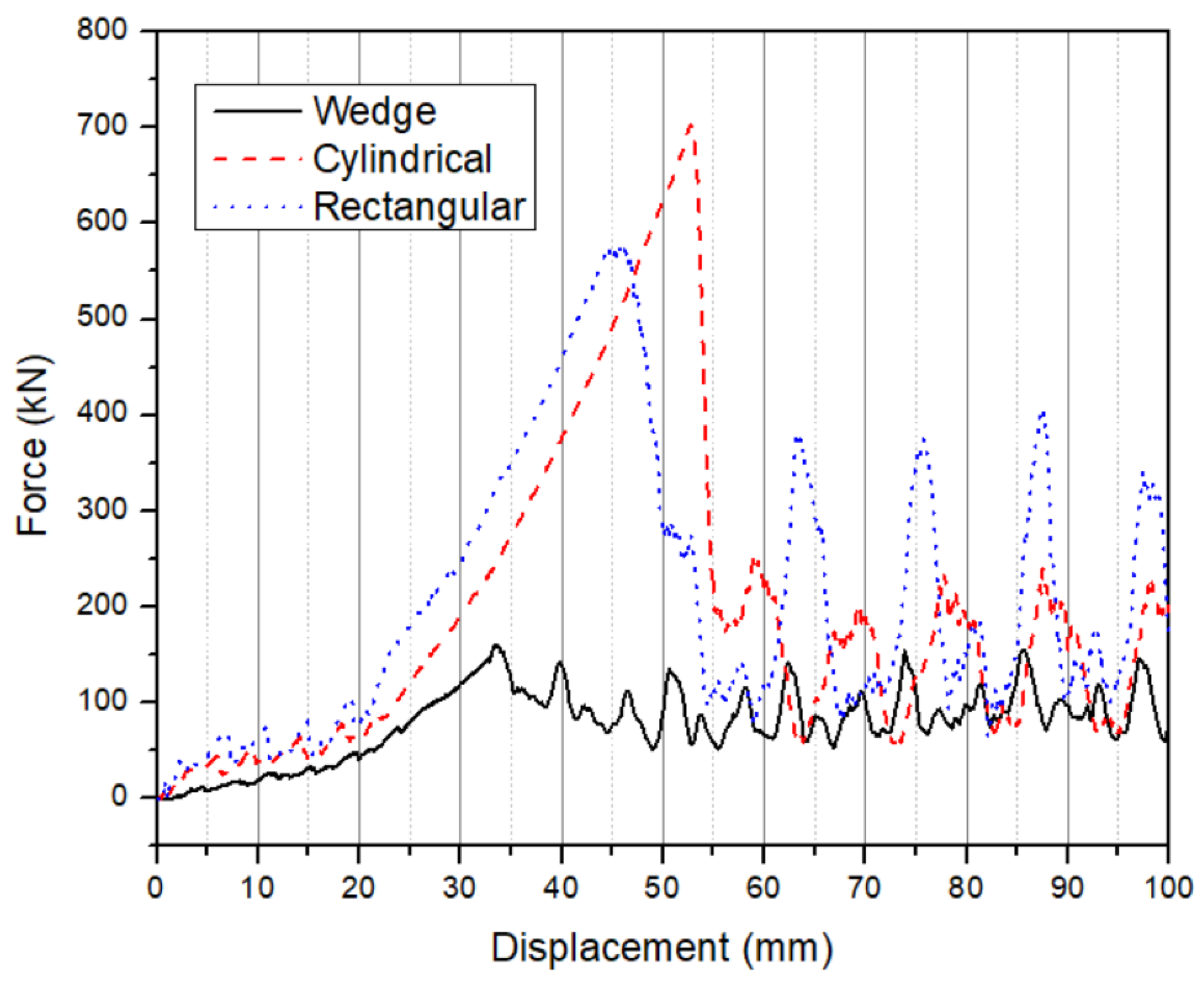
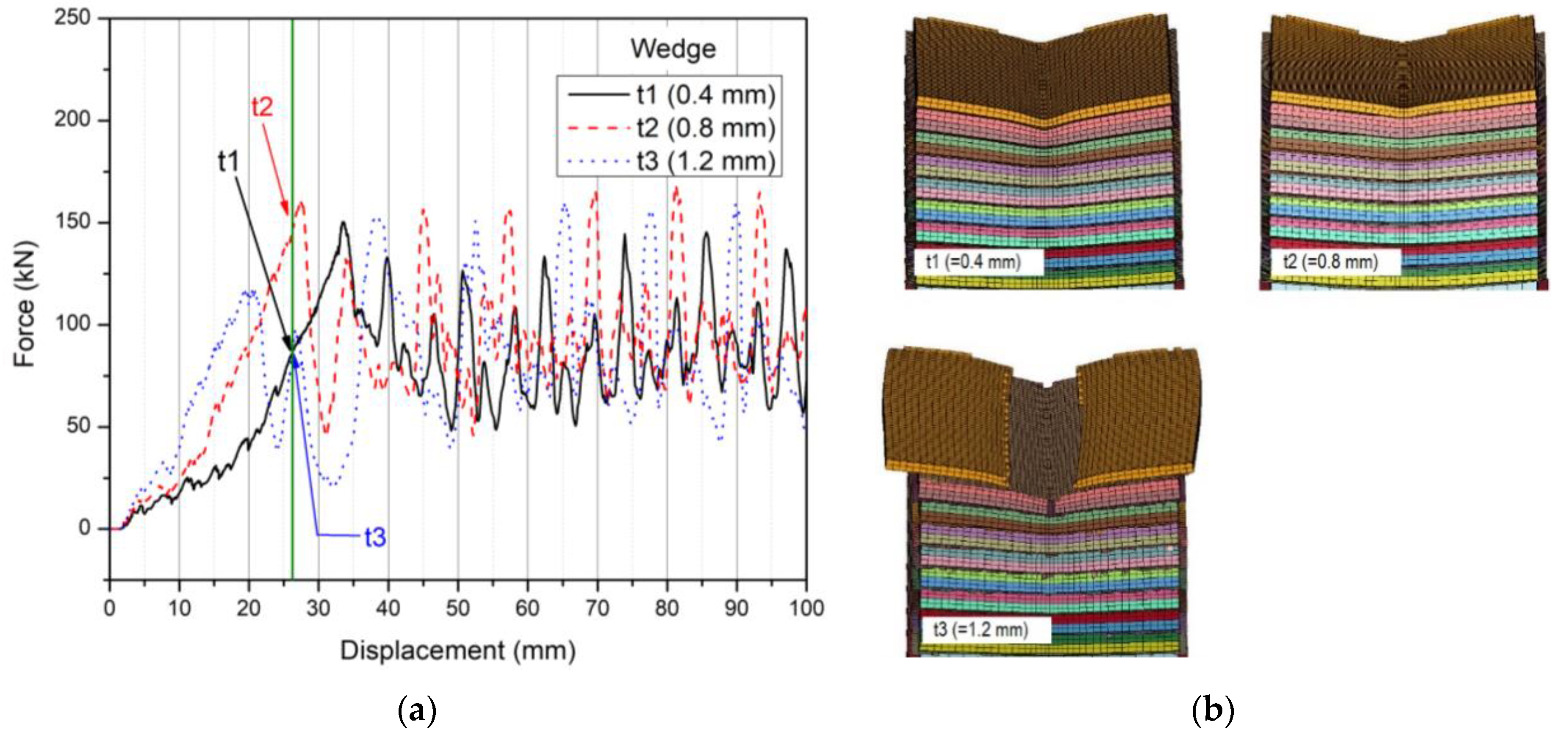
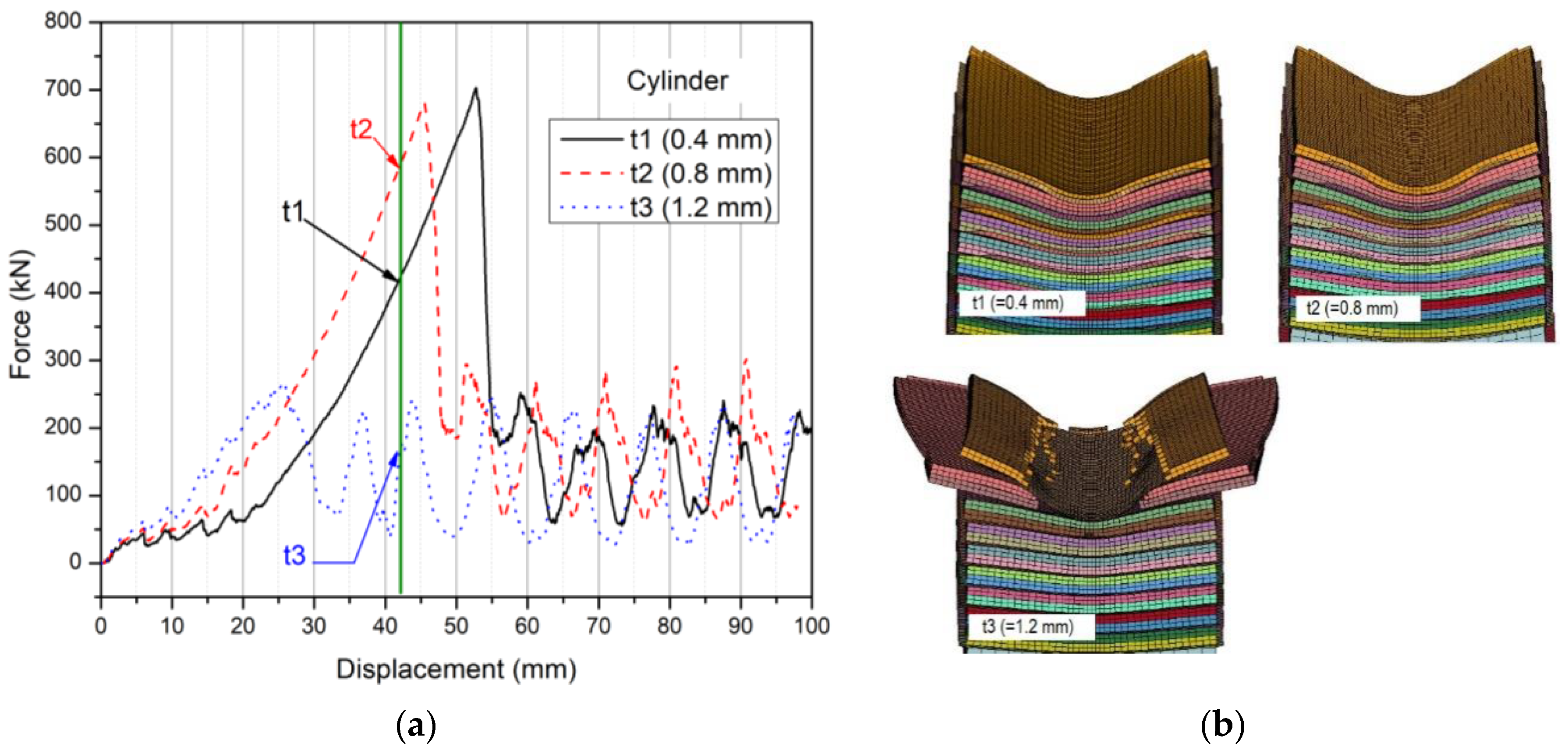
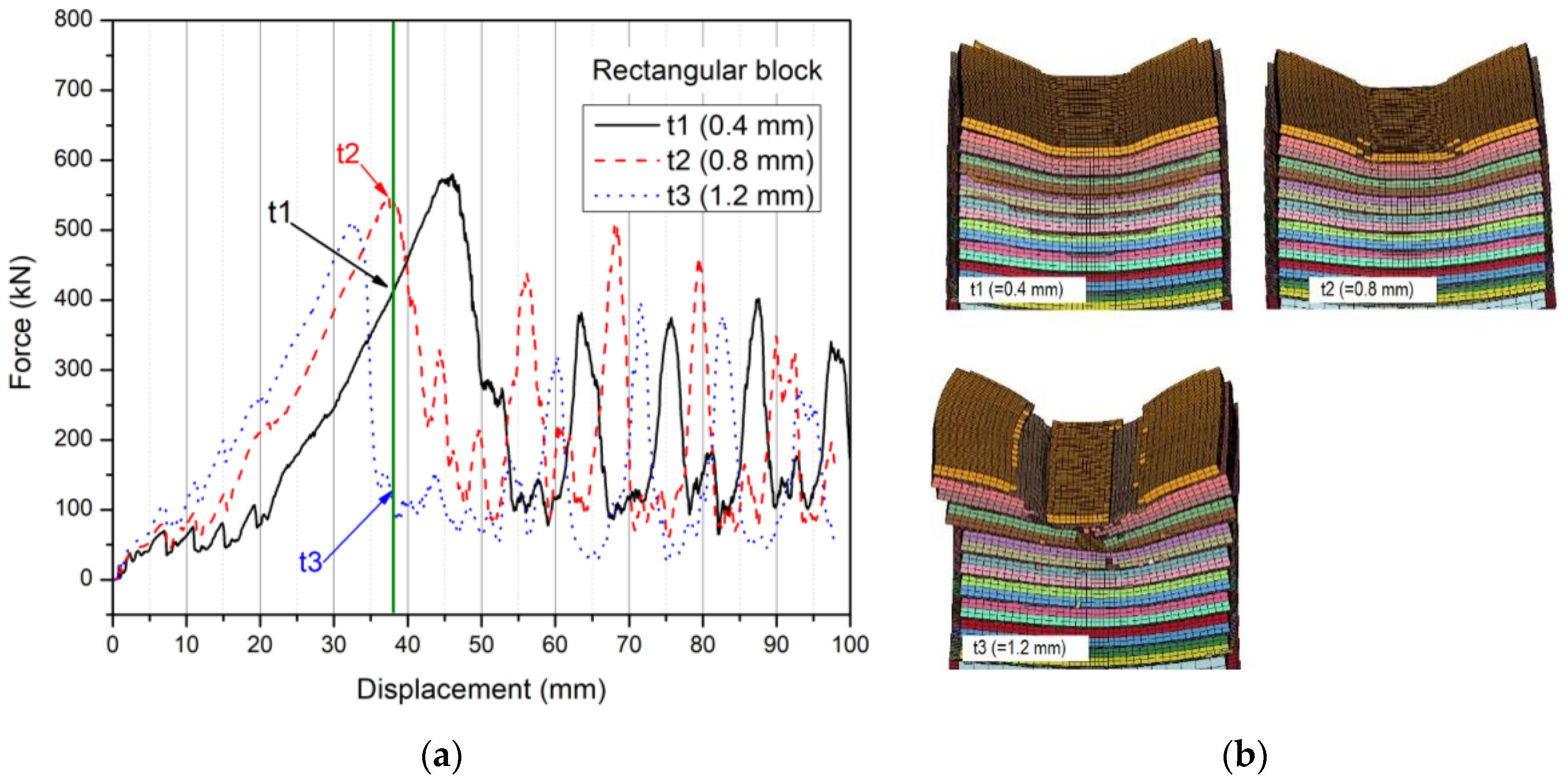
4. Model Application—Effect of Indenter Shape

Using the above battery module model, the effect of various indenters on the module failure mode, force–displacement response, as well as energy absorption is analyzed in this chapter. Two additional indenters, namely a 68.4 mm-diameter cylindrical and a 42.75 mm wide rectangular indenter, are shown in Figure 7, together with the wedge described earlier. In this figure, only the first two layers of the plastic frame on the battery module are shown.

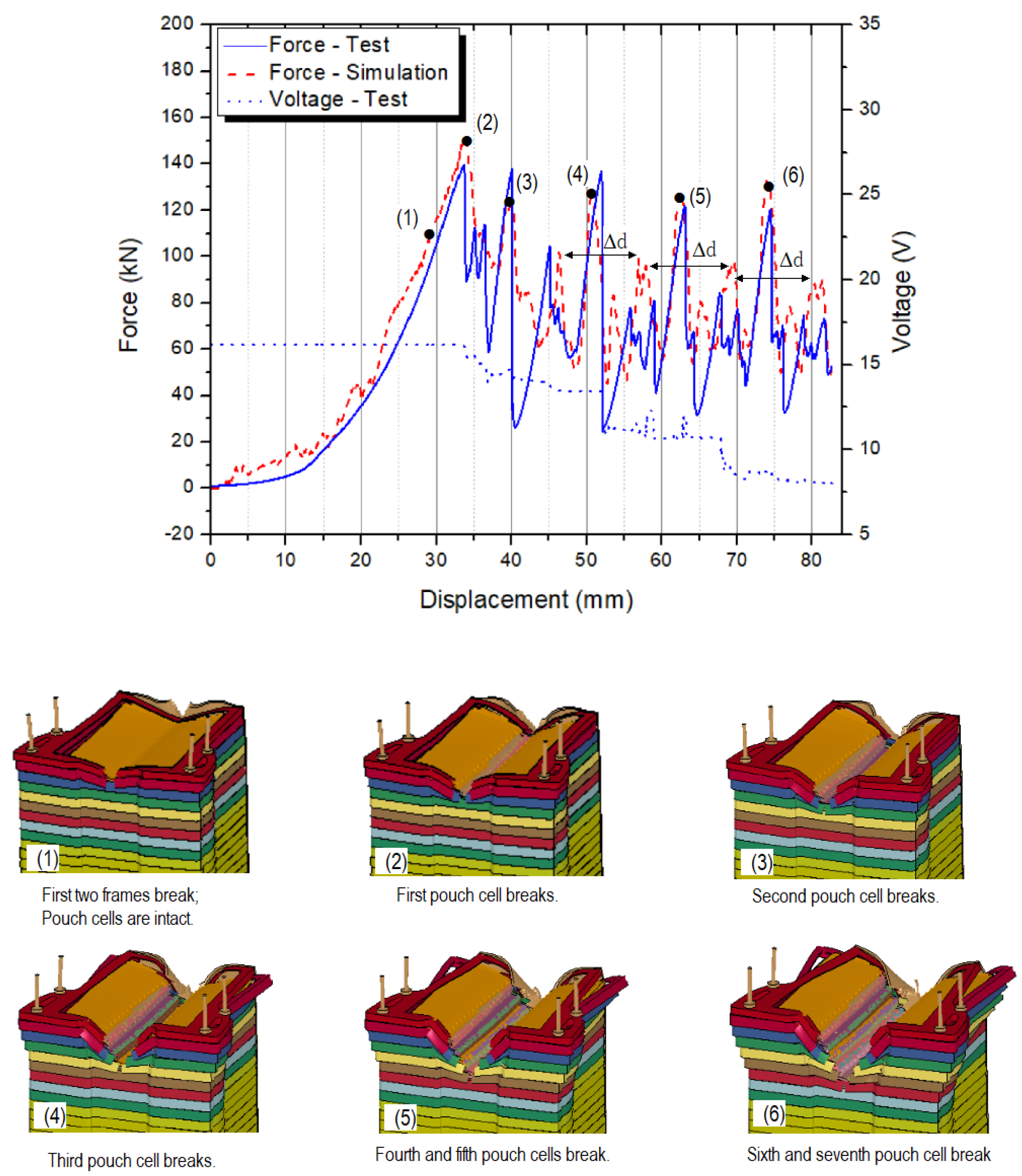
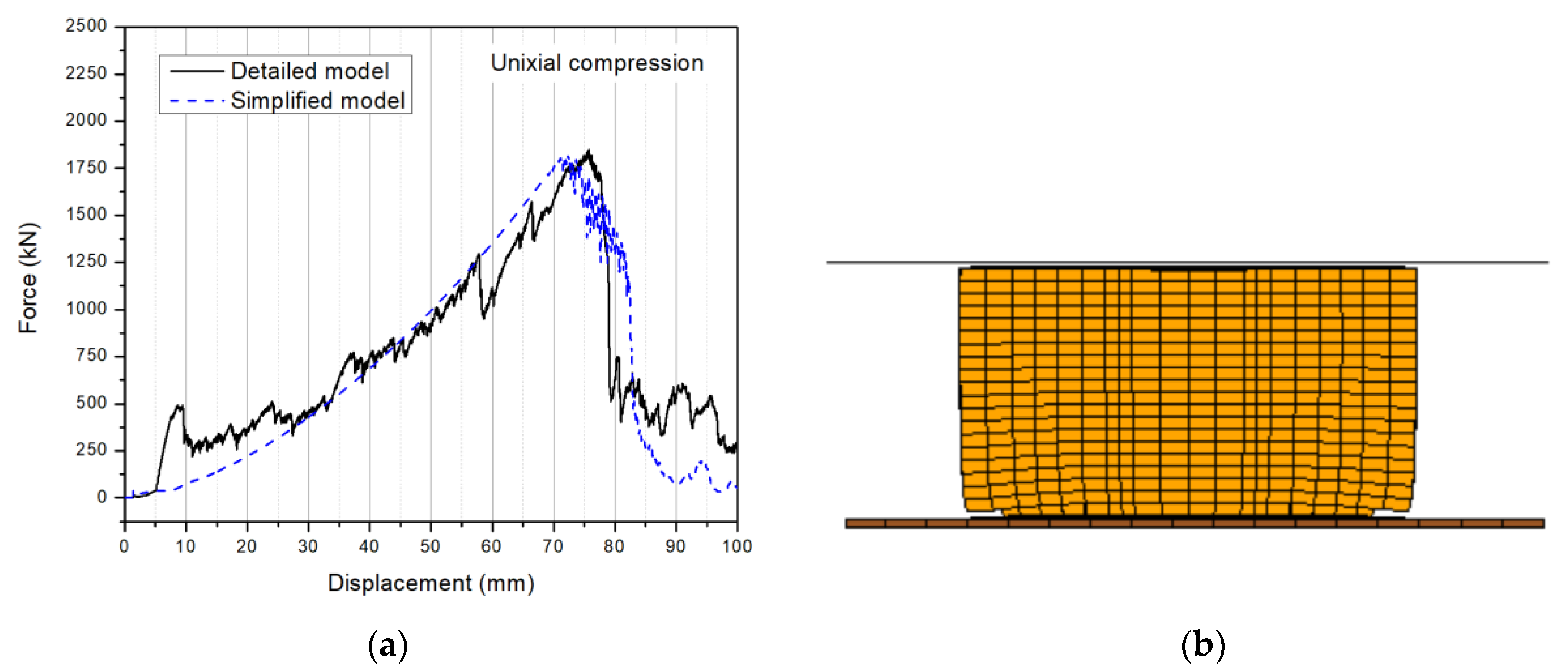
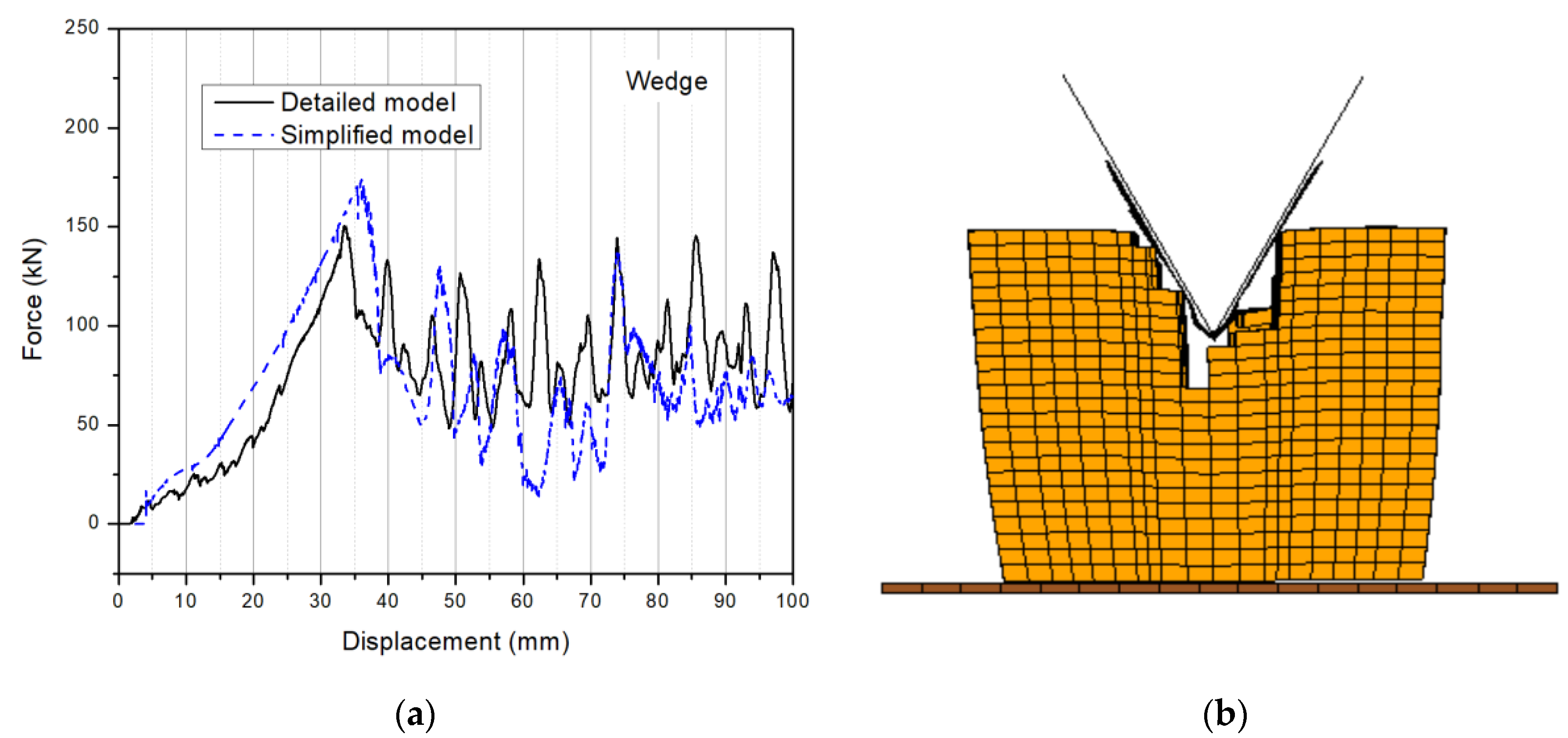
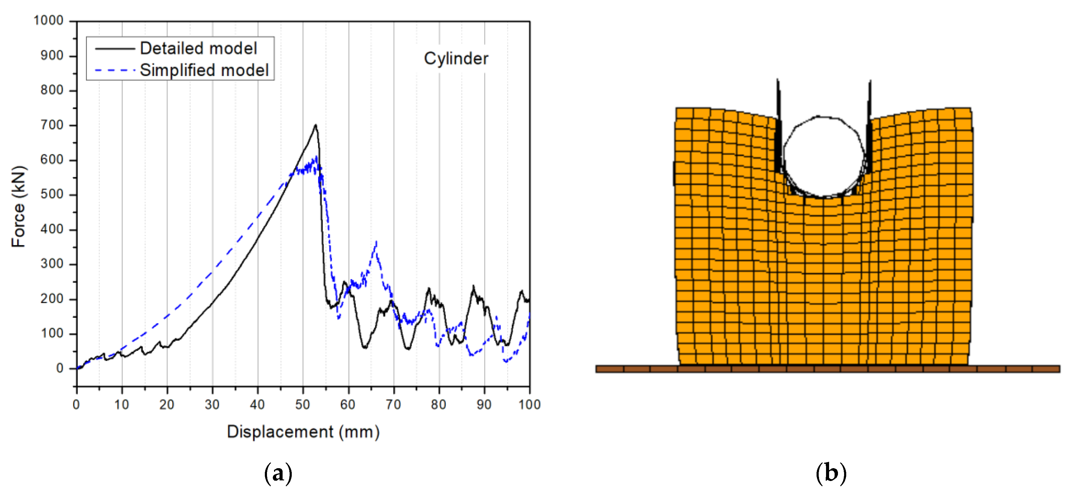
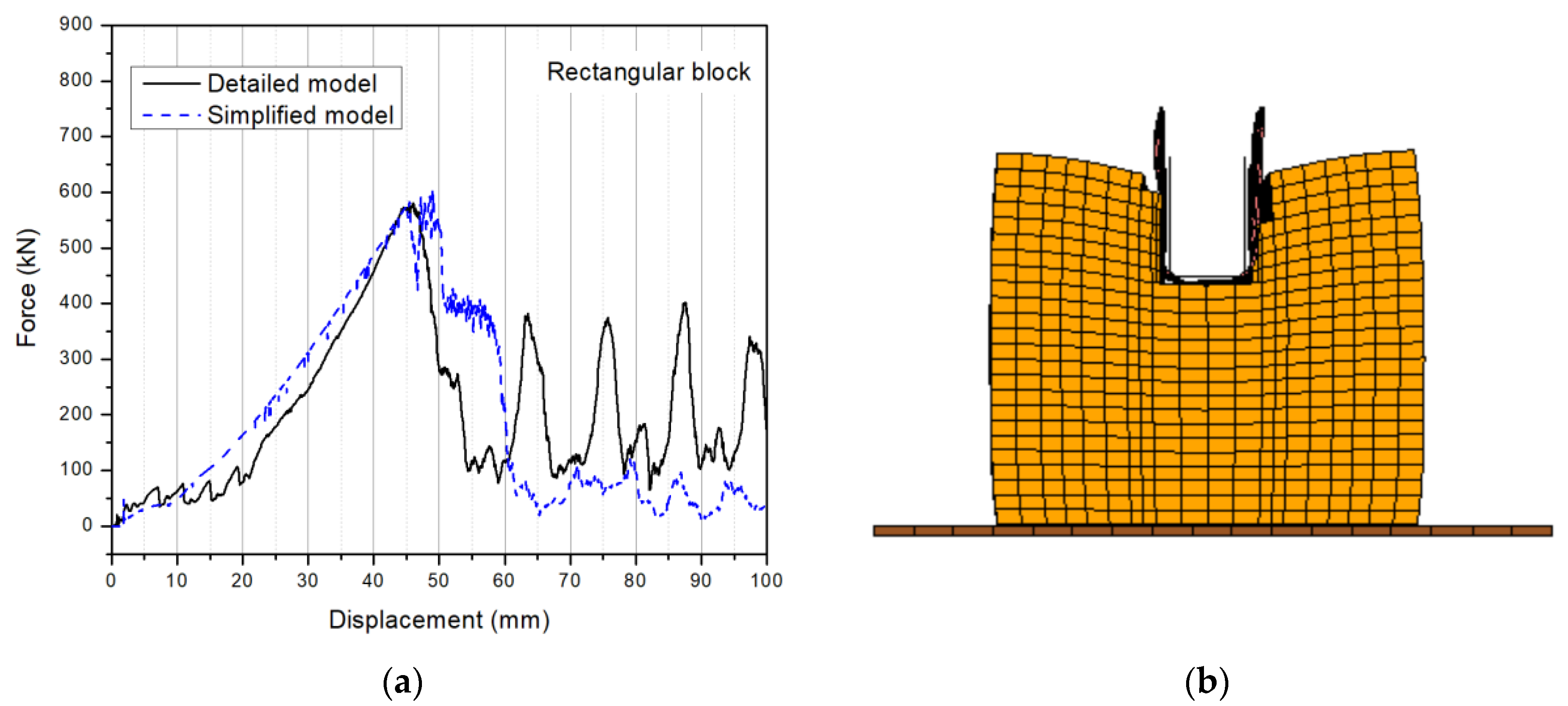
4.1. Failure Modes and Force Response

Crush simulations were conducted on each case up to the experimental maximum displacement of 100 mm. Figure 8 shows the corresponding failure modes of battery modules as well as the deformed cover plates. The steel wedge cuts through the module and split the components into two pieces. It tends to push the structure to expand outwardly, as the wedge goes deeper gradually. In the case of the cylindrical indenter, the degree of structural expansion is slightly smaller. The area under the indenter is subject to combined bending, compression, and shear. The rectangular block produces a more significant shear-type loading, and therefore results in a “plug” penetration in the depth direction, with the least degree of volume expansion.
The model predicted force–displacement curves for all three indentation scenarios are shown in Figure 9. As expected, the force curve for wedge cutting has the lowest peak value and slope because of the wedge shape sharpness and small contact area before the material/structure failures. The short circuit occurs earliest in this case, since the force applied to the battery cell is highly concentrated on a very narrow area, which instigates fracture easily. In the scenario of rectangular block loading, the slope of the force–displacement curve is highest due to the large initial indenter-cover plate contact area. The force–displacement curve for the cylindrical loading exhibits the highest and latest initial peak, which indicates the strongest resistance to the short circuit. This is because the first layer battery cell undergoes a more uniform loading (combined bending, compression, and shear), so more energy is needed to cause its fracture. After the failure of the first pouch cell, the subsequent peak forces in the case of rectangular block loading are higher than those for cylindrical loading, because the rectangular block rapidly densifies the jelly rolls under the indenter, while the cylinder tends to push the material to both sides along with some degree of compression.

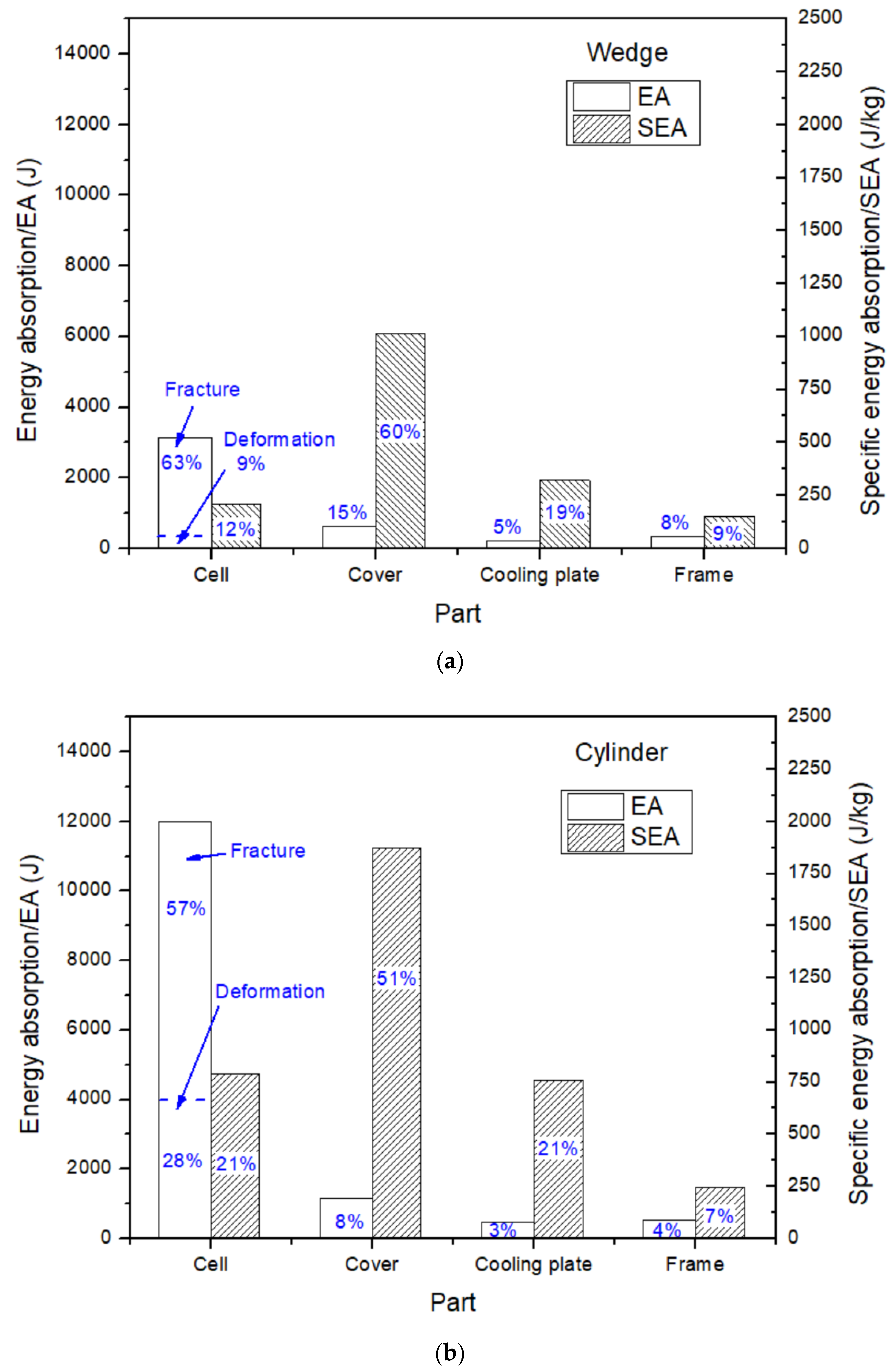
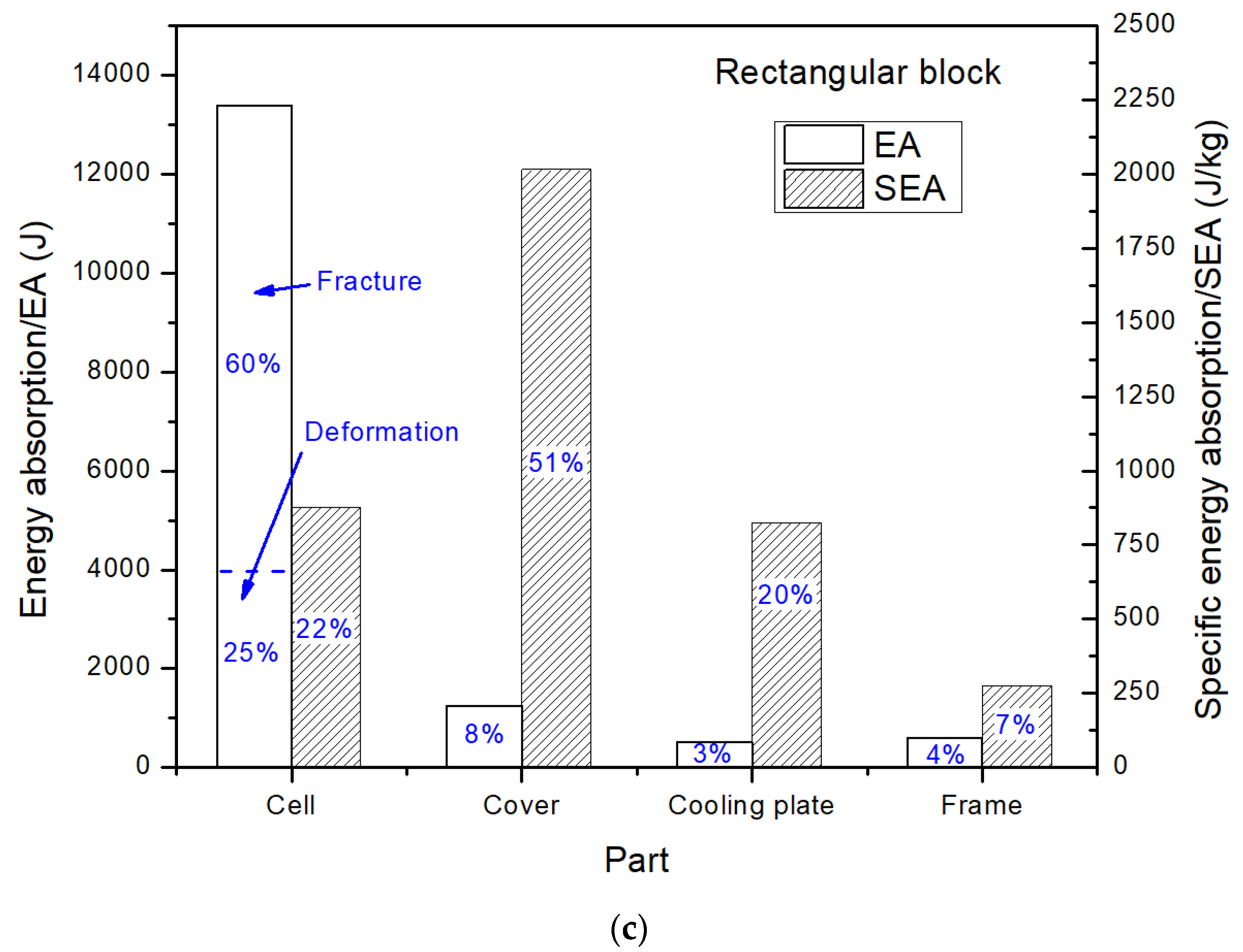
4.2. Energy Absorption

Energy absorption by the battery module was calculated through simulations of all three indentation scenarios. Figure 10 shows the comparison of absolute energy absorption by each component (or part) (denoted as “EA”) and specific energy absorption per unit mass (denoted as “SEA”). The EA for battery cells is further divided into portions due to cell deformation and cell fracture. The small amount of energy loss due to the rod and skew deformation can be reasonably neglected. The results show that modules loaded by cylindrical and rectangular indenters absorbed energies of 14,163 J and 15,752 J, respectively, which is much higher than the EA due to wedge cutting, 4296 J. In all three scenarios, the contribution of each component has a similar trend: Most of the energy is absorbed by battery cells, followed by steel cover plates, aluminum cooling plates, and plastic frames. If normalized by their mass, the SEA of cover plates ranks highest (50–60% of the total SEA). The SEA values for battery cells and cooling plates are similar but lower than those of the cover plates by more than 50%. The contribution of plastic frames is the lowest amongst all four parts. It is noted that in the case of wedge cutting, the SEA of cover plates has a larger portion than in the other two indentation scenarios, which is likely because the battery cells are not sufficiently deformed and compacted by the wedge. Instead, they are pushed away so as to contribute less to energy absorption. A further examination of battery cells EA indicates that energy dissipation during cell fracture seems to be much greater than that during cell deformation. The ratio of fracture to deformation energy absorption for the case of wedge cutting is 5.25, which is higher than that for the cylindrical (2.04) or rectangular block (2.40) indenters. This is because the wedge tends to push the battery cells to both sides, so they do not have much chance to undergo a large compressive deformation, thus absorbing less deformation energy than cylindrical or block indentation scenarios
Based on the analysis above, it can be drawn that Li-ion pouch cells, steel cover plates, and aluminum cooling plates contribute over 90% of the energy absorption during indentation. Assuming that the design of the above battery cells is not changed, considerations are made to further improve energy absorption by altering the cooling and cover plates.

5. Safety Design Considerations for the Battery Module Components

5.1. Design Modification of Aluminum Cooling Plates

For typical battery modules, the cooling plates take the form of thin aluminum sheets with small heat exchanging channels, which are sandwiched between two neighboring battery cells. Efforts have been made to design cooling plates as a multi-functional structure, that is, a heat exchanger and an energy absorber simultaneously. This reduces weight and cost. For example, Shi et al. [11] proposed sandwich configurations for cooling plates for a battery module with four pouch cells and demonstrated good energy absorbing performance. However, this design may work well on a relatively small battery module with few battery cells, but not necessarily a larger one such as the module we study here. Since sandwich plates are generally much thicker than monolithic solid counterparts with the same weight, the replacement of thin, solid cooling plates by sandwich structures would significantly increase the size of a battery module. Considering that there are over 30 cooling plates in the present battery module, it is not practical to use sandwich structures or significantly increase the space between two cooling plates or space between a cooling plate and a Li-ion pouch cell. Here, we will simply increase the cooling plate thickness to study its effect. In the current cooling plate design, due to their thinness (t = 0.4 mm), any contribution to the load-bearing or energy absorption is limited. In this study, the thickness was increased to 0.8 mm and then also 1.2 mm to study the influence on overall module structural response. When increasing t from 0.4 to 1.2 mm, the weight increase of the whole module is only 1.24 kg, which is acceptable considering it was about 20 kg originally. The volume of the battery has minimal volume change.
Simulations were conducted for all the three indenter scenarios, each with three different cooling plate thicknesses. Figure 11, Figure 12 and Figure 13 show the model predicted force–displacement curves as well as the battery cell failure modes at displacements of 27 mm (wedge), 42 mm (cylinder), and 38 mm (rectangular block), respectively. Based on the curves shown in Figure 11a, Figure 12a and Figure 13a, one can see that for all the three indentation scenarios, a thicker cooling plate does not substantially improve energy absorption. Instead, the EA tends to decrease with increasing thickness. When increasing t from 0.4 to 0.8 mm, the short circuit occurs earlier (indicated by a smaller displacement corresponding to the first force peak) and with a lower force value. When the thickness is further increased to 1.2 mm, the short circuit occurs even earlier, and the peak force keeps decreasing. This trend is especially significant for cylindrical indenter loading. This is due to the different structural failure mechanisms caused by cooling plates with various thicknesses. As shown in Figure 11b, Figure 12b, and Figure 13b, thicker cooling plates increase the structural stiffness, serving as a more “rigid” foundation. As consequence, pouch cells immediately above it can be easily cut by the indenter and then shortened. This effect can be observed in a few of the top layers. A thinner cooling plate does not have much resistance to an indenter, so the pouch cells are pushed to move downwards and significantly densify before fracture. In this way, a higher force and more energy are needed to damage the cells and produce a short circuit. Therefore, in the present battery module, cooling plates with smaller thickness may improve their safety. This finding is consistent with results reported by Kalnaus et al. [7] that the presence of cooling plates reduces energy absorption.

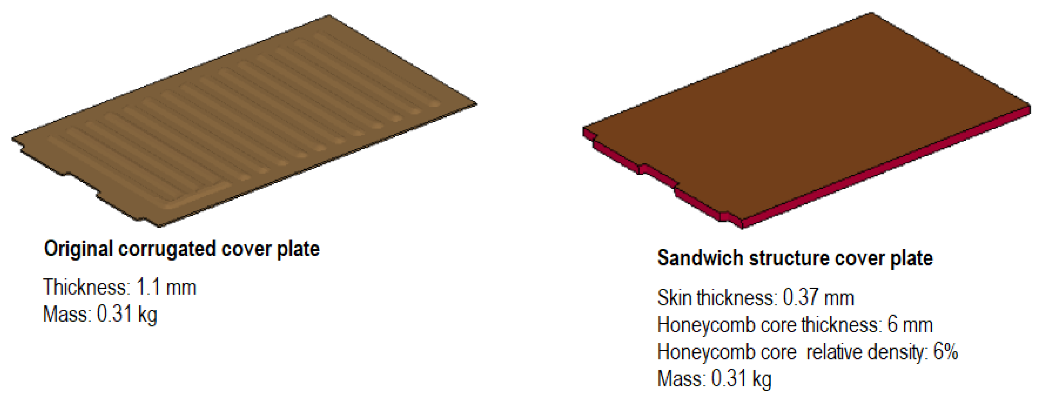
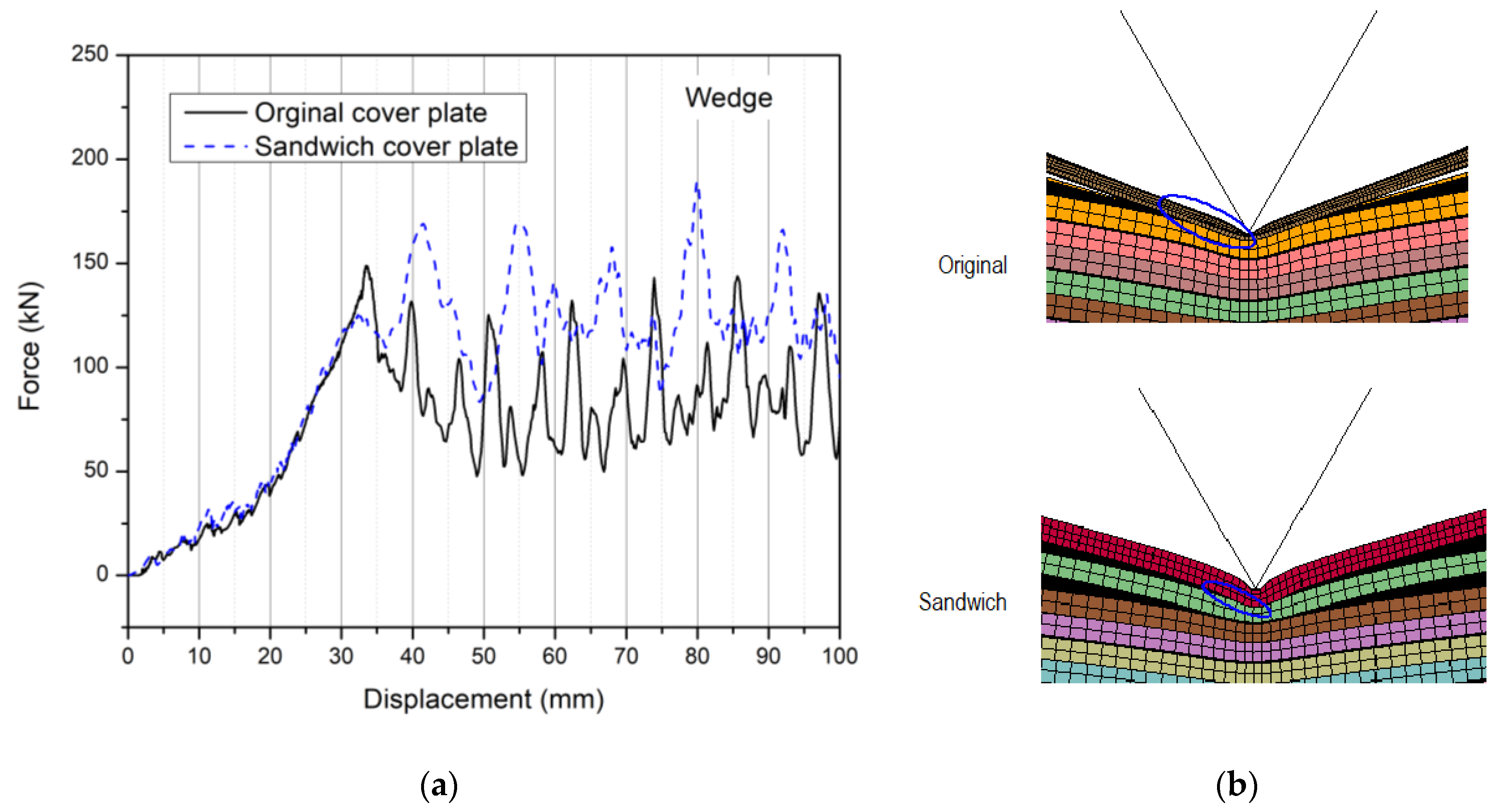
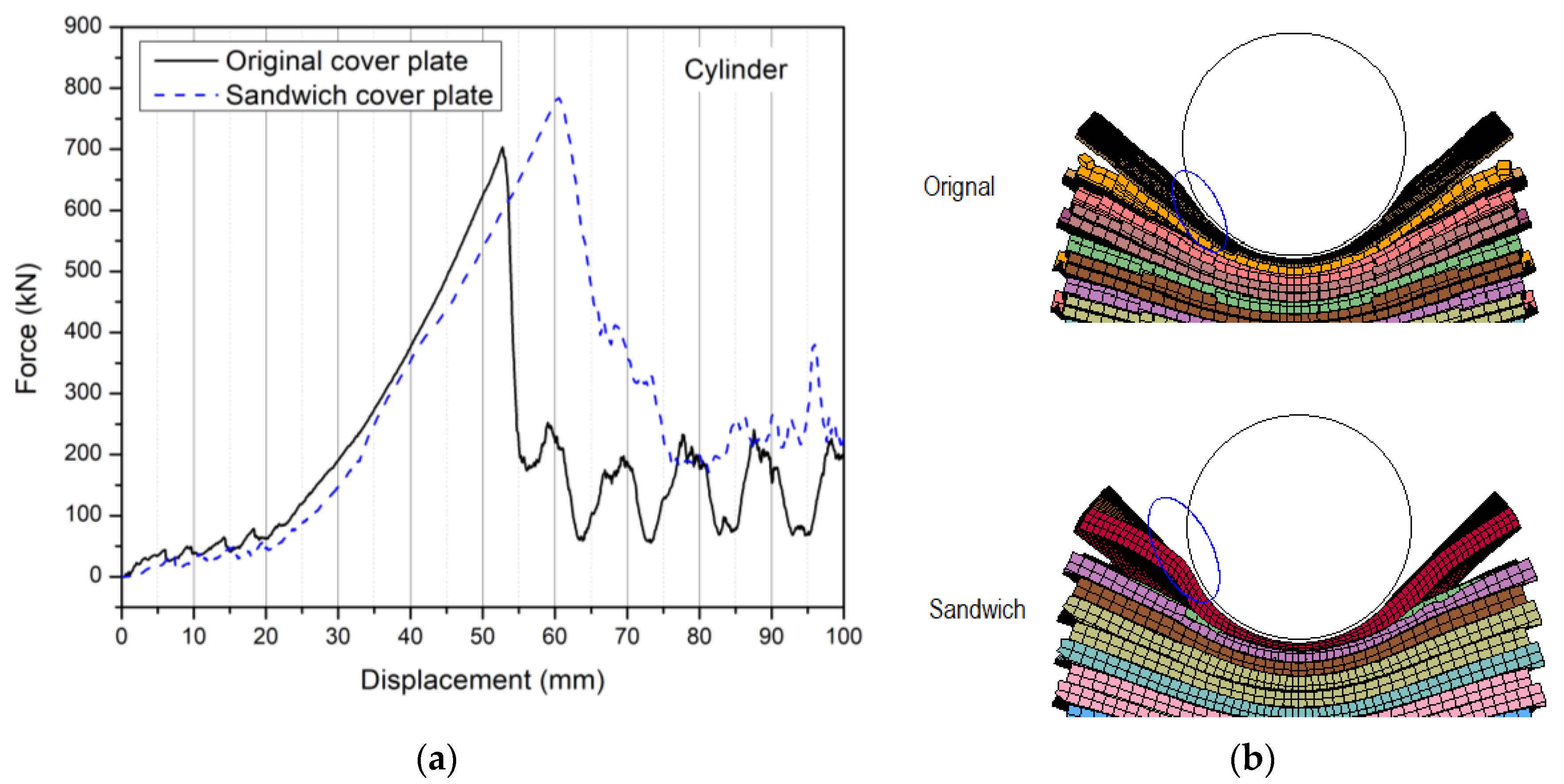
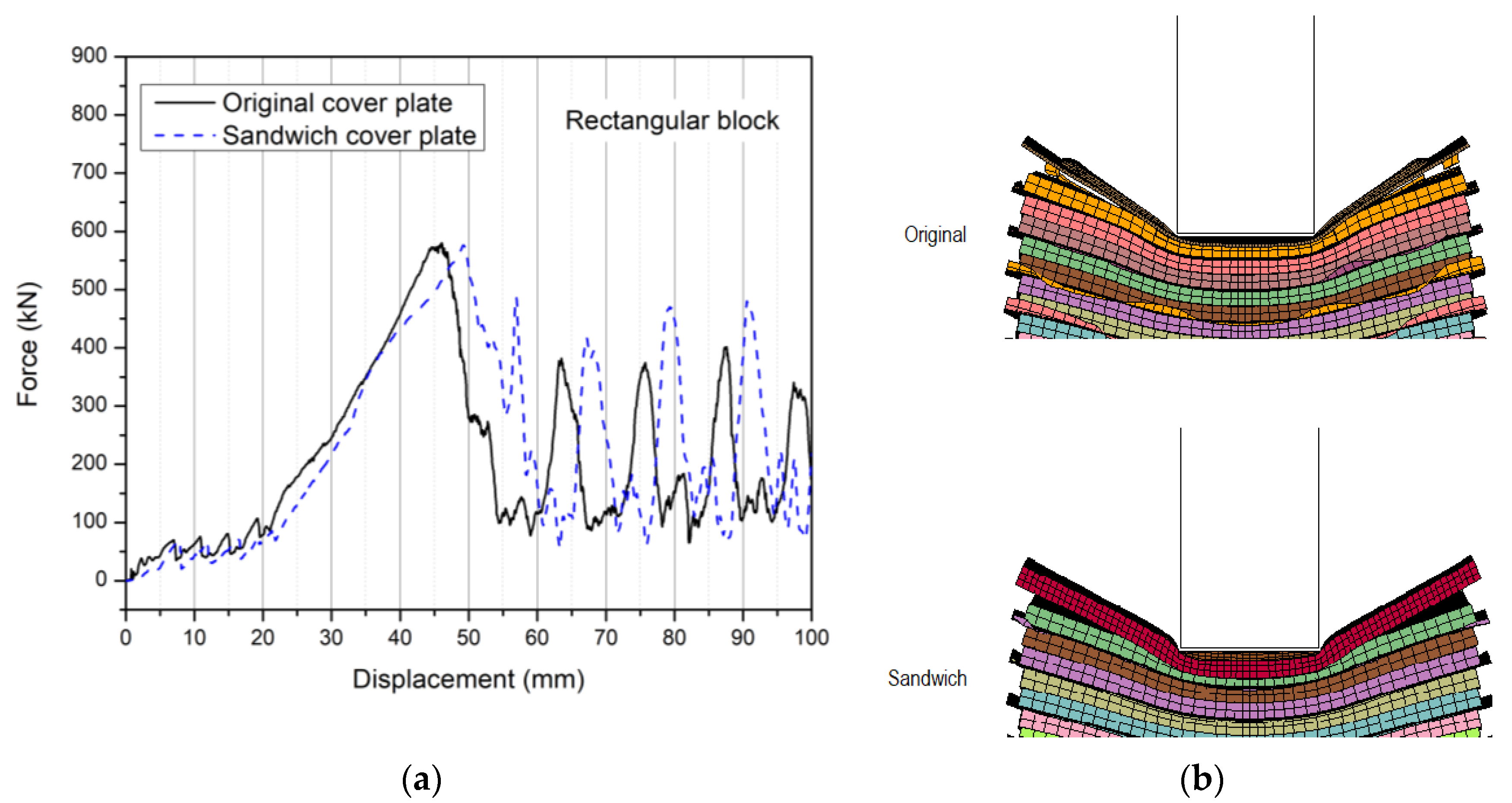
5.2. Design Modification of the Cover Plate

In this section, the steel cover plate is modified to study its protective performance. The results in Section 3 and Section 4 have demonstrated the significant effect of a cover plate on the force magnitude and displacement for the failure of battery cells in the first layer, which indicates the initiation of a short circuit. The cover plate can control the overall structural deformation mode during crush loading, which further dominates energy absorption and failure behavior. Generally, a global deformation is preferred over a localized one, since the former can produce a stronger resistance to punch loading, increase the force, and absorb more energy before failure. So, in theory, a very thick, high stiffness panel should be able to prevent localized deformation and force the whole structure to deform more predominantly in one dimension. Then, crush loading by a wedge or a punch with other shapes would all produce uniaxial compression to the module, although the mass and volume of the cover plate may increase significantly as a penalty. In this study, we would not like to increase the mass of the cover plate. Instead, a new sandwich panel structure was designed and used to replace the original cover plate without changing mass. Since there are only two cover plates, the module volume is not increased substantially. Performances were compared through FE simulations. Figure 14 shows the current and new cover plate models. The original design (left) is a typical corrugated steel plate with a thickness of 1.1 mm and a mass of 0.31 kg. The new cover plate (right) was designed as a three-layered sandwich panel, where the two facing skins are 0.37 mm thick, and the core was assumed to be a hexagonal honeycomb structure made from the same steel. The relative density and thickness of the honeycomb were set as 6% and 6 mm, respectively. These parametric values ensure that the two designs have the same weight, where thin facing skins offset the weight of the honeycomb core. For the sandwich structure, the two facing skins were modeled with thin shell elements, while the honeycomb core was modeled with solid elements, and its constitutive behavior was represented using the previously described homogeneous material law for cellular solids, MAT-63. Its effective out-of-plane Young’s modulus Ec and plateau stress σc can be estimated using Equations (4) and (5) [20,21], respectively.
E c = ρ ¯ E s
σ c = 3.2 ρ ¯ 5 3 σ s
where ρ ¯ is relative density while Es and σs are the Young’s modulus and yield strength of steel, respectively.
The sandwich structure cover plate was used to replace the original one in the battery module, and simulations were conducted under the same three indentation scenarios: wedge, cylinder, and rectangular block. The simulated force–displacement curves and failure modes at the first peak force for the original and new sandwich structure designs for all three scenarios are compared in Figure 15, Figure 16 and Figure 17, respectively. The results indicate that the sandwich-type cover plate has various effects when subjected to different indenters. In the case of wedge cutting, as shown in Figure 15a, the application of a sandwich-type cover plate reduces the first peak force from 150 to 125 kN, which means that the short circuit initiates at a lower force. This can be explained by observing the failure modes of the original design and new design in Figure 15b. The small middle area of the honeycomb core in the sandwich panel is compacted by the sharp wedge edge. Since the skins are very thin (0.37 mm), they are easily bent to form a small “tip” immediately under the wedge. This tip reduces the contact area (marked using a blue circle) between the cover plate and pouch cell around it, thereby reducing the force needed to cut through the cell below it. In the original design, the cover plate is relatively thick (1.1 mm). So, a blunter tip is formed, which causes a higher force for cell fracture. However, in subsequent loading, the sandwich cover increases the structural resistance, which is indicated by higher peak forces. This is due to the gradual densification of the honeycomb core, so a large amount of energy is absorbed. Metal honeycombs crushed out-of-plane are amongst the best of all known energy-absorbing materials/structures.
When the module is loaded by a cylindrical indenter, as one can see in Figure 16a, the new design can increase the peak force from 700 to 785 kN and delay the displacement for the initial short circuit by about 10 mm. This indicates that the application of a sandwich structure-type cover plate can better protect the battery in this cylinder indentation scenario than a solid cover plate. The mechanism is shown in Figure 16b. Thinner face sheets and a compliant honeycomb core as used in the new design can “wrap” around the cylinder to a higher degree than a solid cover plate and increase the contact area (marked using a blue circle). As a consequence, the force increases, and the peak force is delayed while the thick honeycomb densifies.
In the case of rectangular indentation, as one can see in Figure 17a, the sandwich-type cover plate does not cause evident change to the first force peak; both designs yield almost the same deformation mode, as shown in Figure 17b. Displacement corresponding to the initial short circuit is shifted to the right by about 5 mm, which is slightly less than the honeycomb core thickness of 6 mm. Again, the displacement shift is considered to be caused by core compression. It is also noted that in all three indentation scenarios, the new sandwich-type cover plate design always raised the force level after the first peak, which helps resist loads. Furthermore, since a metal honeycomb is involved in the deformation process, more and more energy is dissipated as the indenter penetrates deeper. Overall, the sandwich-type cover plate can improve module safety under crush loading. Although, particular attention should be paid when subjected to a very sharp indenter such as a wedge, where thicker facing skins may be needed.

6. Module FE Model Simplification

The FE models described in Section 3, Section 4 and Section 5 have demonstrated promise for studying detailed failure mechanisms of Li-ion battery modules under various loading conditions. However, each of these models has over 270,000 elements, and each automobile battery pack may include seven to eight such battery modules. Therefore, using present common computing power, it is not realistic to integrate the detailed battery models of this work to an entire vehicle model, which may have over one million elements. The integrated model has too many elements to make computational costs affordable and time to wait reasonable. To study the overall response of an EV subject to a crash, the battery models must be simplified.
In this section, the effort has been made toward battery module FE model simplification to achieve two goals: (1) reduce the number of elements for the module to less than 10,000; and (2) use a homogeneous material law to represent the complicated module structure. To achieve (1), only the exterior profile of the battery module was kept and re-meshed with 10 mm solid elements. Since the pouch cell stack is the main part of the module, the whole module was described with MAT-63. However, the top steel cover plate was kept, since it controls the overall deformation mode during the early stages of deformation. To obtain the “equivalent” stress–strain curve for the simplified model, a uniaxial compressive simulation was conducted on the detailed FE model, as shown in Figure 18. The metal rods and bolts were removed, and the holes at the bottom were constrained. Then, the force–displacement curve was converted to a stress–strain curve and then used as input for the simplified model.
Uniaxial compression, wedge indentation, as well as cylinder and rectangular block indentation simulations were performed on the simplified models. The results are compared to predictions made using the prior detailed models in Figure 19, Figure 20, Figure 21 and Figure 22. To better match the force responses, a trial-and-error method was used to tune the failure criterion. It was found that a maximum failure strain of 0.2~022 yielded the closest agreement. The cover plate was set thicker (=2 mm) to increase structural stiffness and take into account constrained boundaries.
The results show that the simplified models can basically predict the conditions of the initial short circuit in all three indentation scenarios, i.e., the first force peak and its corresponding displacement. However, the subsequent failure response of the battery was not as well captured, since the simplified model is not able to represent the multiple-layered structure within the battery module as accurately as the detailed model. Consider that constraint afforded by rods and bolts cannot be modeled, but only approximated by using a thicker cover plate. In addition, mesh size may affect the results. A comparison was made that indicated that the current element size (=10 mm) yielded the best results under the number of elements limit: 10,000. In summary, this simplified model can significantly reduce computational time and reasonably predict the short circuit initiation. Simplified effective models of complex processes have substantial merit in many fields; refinement is often necessary.

7. Conclusions

In this study, a low-speed wedge cutting test was performed on a vehicle battery module. The force–deflection response showed multiple peaks, which corresponded to the sequential damage of plastic frames and Li-ion battery cells. Voltage dropped in a corresponding stepwise manner, indicating a sequential short circuit of battery pouch cells. Based on the tests, a numerical model was developed to simulate the wedge indentation response of the battery module. The metallic parts, including steel bars, screws and cover plate, aluminum cooling plate, as well as plastic top panel and frames were modeled with an elastoplastic constitutive law. Pouch cells behave as a low-density porous medium, so they were simulated with a material model for compressible foams. The numerical model captured the failure modes of the specimen, and the model predicted force–displacement responses demonstrated a similar trend to the test data.
The battery module FE model was used to study the effect of two new indenters, including a 68.4 mm-diameter cylinder and a 42.75 mm wide rectangular block. The results show that the cylinder produced the highest peak force, which was followed by the rectangular block. In both cases, the force levels were much higher than those for the wedge. An analysis of energy absorption shows that modules loaded by the cylindrical and rectangular block indenters absorb much more energy than wedge cutting. In all three scenarios, the contribution of each part had a similar trend: Most of the energy is absorbed by the battery Li-ion cells and then followed by the steel cover plates, aluminum cooling plates, and plastic frames. If normalized by mass, the specific energy absorbed (SEA) by the cover plate ranks the highest. The SEA values for battery cells and cooling plates are similar but lower than that of the cover plate by more than 50%. The contribution of the plastic frames is the lowest amongst all the four components. A further examination of the energy absorbed (EA) by battery Li-ion cells indicates that energy dissipation during cell fracture is much greater than that during cell deformation.
Safety design considerations have been made by modifying the aluminum cooling plates and steel cover plate. The thickness of the cooling plate was increased from 0.4 to 0.8 and then 1.2 mm. The simulation results revealed that a thicker cooling plate does not improve energy absorption. Instead, energy absorption tends to decrease with increasing thickness. Furthermore, when increasing the thickness, the short circuit occurs earlier (indicated by a smaller displacement corresponding to the first force peak) and with a lower force. The geometry and material of the cover plate can significantly change the failure character of battery modules and their overall structural response. A sandwich structure cover plate was also modeled, which can improve module safety under crush indentation loading. Particular attention to facing skin thickness should be paid when subjected to a very sharp indenter such as a wedge. Highly vented honeycomb cores [22] can be considered for energy absorption and cooling combined.
To reduce the computational cost of the detailed FE model, a simplified model was developed by representing the battery module using the crushable foam material law. A uniaxial compression simulation was performed to calibrate its input stress–strain curve. Then, all three indentation scenarios—wedge, cylinder, and rectangular block—were simulated. The results showed that this simplified model can reasonably predict the short circuit initiation of the battery module but not the subsequent structural response. Fine-tuning its parameters and performance are suggested. In the future, results produced in a similar way are suggested to be compared with crash test data available for EVs having similar battery systems for maximum real-world benefit.

Author Contributions

Methodology, Formal analysis, Writing-Orinal Draft Preparation, Project administration, F.Z.; Software, Validation, Investigation, R.Z.; Investigation, Writing-Review & Editing, D.J.S. All authors have read and agreed to the published version of the manuscript.

Funding

This work is partially supported by MIT Battery Consortium and Ford Motor Company, which is gratefully acknowledged. Also, the NSF Major Research Instrumentation Program for the Instron 8802 test system along with ERAU for numerous small equipment and supplies.

Informed Consent Statement

Not applicable.

Data Availability Statement

The data presented in this study is partially available on request from the corresponding author. The data is not publicly available due to the requirement of sponsor.

Acknowledgments

We would like to thank Jianyin Lei, Xianping Du, and Marian Bulla for their contributions in CAD and initial FE model development.

Conflicts of Interest

The authors declare no conflict of interests.

References

  1. Vehicles—Department of Energy: Energy.gov. Available online: energy.gov (accessed on 5 March 2014).
  2. Zhu, J.; Wierzbicki, T.; Li, W. A review of safety-focused mechanical modeling of commercial lithium-ion batteries. J. Power Sources 2018, 378, 153–168. [Google Scholar] [CrossRef]
  3. Deng, J.; Bae, C.; Marcicki, J.; Masias, A.; Miller, T. Safety modelling and testing of lithium-ion batteries in electrified vehicles. Nat. Energy 2018, 3, 261–266. [Google Scholar] [CrossRef]
  4. Kermani, G.; Sahraei, E. Review: Characterization and modeling of the mechanical properties of lithium-ion batteries. Energies 2017, 10, 1730. [Google Scholar] [CrossRef] [Green Version]
  5. Liu, B.; Jia, Y.; Yuan, C.; Wang, L.; Gao, X.; Yin, S.; Xu, J. Safety issues and mechanisms of lithium-ion battery cell upon mechanical abusive loading: A review. Energy Storage Mater. 2020, 24, 85–112. [Google Scholar] [CrossRef]
  6. Lai, W.J.; Ali, M.Y.; Pan, J. Mechanical behavior of representative volume elements of lithium-ion battery modules under various loading conditions. J. Power Sources 2014, 248, 789–808. [Google Scholar] [CrossRef]
  7. Kalnaus, S.; Wang, H.; Watkins, T.R.; Kumar, A.; Simunovic, S.; Turner, J.A.; Gorney, P. Effect of package and cooling plates on mechanical response and failure characteristics of Automotive Li-ion battery modules. J. Power Sources 2018, 403, 20–26. [Google Scholar] [CrossRef]
  8. Xia, Y.; Wierzbicki, T.; Sahraei, E.; Zhang, X. Damage of cells and battery packs due to ground impact. J. Power Sources 2014, 267, 78–97. [Google Scholar] [CrossRef]
  9. Xia, Y.; Chen, G.; Zhou, Q.; Shi, X.; Shi, F. Failure behavior of 100% SOC lithium-ion battery modules under different impact loading conditions. Eng. Fail. Anal. 2017, 82, 149–160. [Google Scholar] [CrossRef]
  10. Chen, G.; Li, W.; Luo, H.; Xia, Y. Influence of mechanical interaction between lithium-ion pouch cells in a simplified battery module under impact loading. In Proceedings of the ASME International Mechanical Engineering Congress and Exposition (IMECE 2017), Tampa, FL, USA, 3–9 November 2017. [Google Scholar]
  11. Shi, Z.; Chen, G.; Zhu, L.; Li, J.; Xia, Y. Sandwich structure design of a cooling fin for battery modules against impact loads. Automot. Innov. 2020, 3, 260–269. [Google Scholar] [CrossRef]
  12. Zhu, F.; Du, X.; Lei, J.; Audisio, L.; Sypeck, D. Experimental study on the crushing behavior of lithium-ion battery modules. Int. J. Crashworthiness 2020. [Google Scholar] [CrossRef]
  13. Sahraei, E.; Meier, J.; Wierzbicki, T. Characterizing and modeling mechanical properties and onset of short circuit for three types of lithium-ion pouch cells. J. Power Sources 2014, 247, 503–516. [Google Scholar] [CrossRef]
  14. Sahraei, E.; Kahn, M.; Meier, J.; Tomasz, W. Modelling of cracks developed in lithium-ion cells under mechanical loading. RSC Adv. 2015, 5, 80369–80380. [Google Scholar] [CrossRef]
  15. Wang, H.; Kumar, A.; Simunovic, S.; Allu, S.; Kalnaus, S.; Turner, J.A.; Helmers, J.C.; Rules, E.T.; Winchester, C.S.; Gorney, P. Progressive mechanical indentation of large-format Li-ion cells. J. Power Sources 2017, 341, 156–164. [Google Scholar] [CrossRef] [Green Version]
  16. Sahraei, E.; Campbell, J.; Wierzbicki, T. Modeling and short circuit detection of 18650 Li-ion cells under mechanical abuse conditions. J. Power Sources 2012, 220, 360–372. [Google Scholar] [CrossRef]
  17. LS-DYNA Keyword User’s Manual, Volume II: Materials Models; Livermore Software Technology Corp.: Livermore, CA, USA, 2018.
  18. Zhu, F.; Du, X.; Lei, J.; Audisio, L.; Sypeck, J. Numerical Modeling of Lithium-Ion Battery Cells and Modules Subjected to Low Speed Indentation; SAE Technical Paper; SAE International: Warrendale, PA, USA, 2020. [Google Scholar]
  19. Chung, S.H.; Tancogne-Dejean, T.; Zhu, J.; Luo, H.; Wierzbicki, T. Failure in lithium-ion batteries under transverse indentation loading. J. Power Sources 2018, 389, 148–159. [Google Scholar] [CrossRef]
  20. Zhang, J.; Ashby, M.F. The out-of-plane properties of honeycombs. Int. J. Mech. Sci. 1992, 34, 475–489. [Google Scholar] [CrossRef]
  21. Cote, F.; Deshpande, V.S.; Fleck, N.A.; Evans, A.G. The out-of-plane compressive behavior of metallic honeycombs. Mater. Sci. Eng. A 2004, 380, 272–280. [Google Scholar] [CrossRef] [Green Version]
  22. Sypeck, D.J. Highly Vented Truss Wall Honeycomb Structures. U.S. Patent 9,845,600 B2, 19 December 2017. [Google Scholar]
Figure 1. (a) Configuration of the battery system (modules, and pack) in a Chevrolet Volt. (Modified from https://gm-volt.com/); (b) Configuration of the battery module; (c) Photograph of the wedge; (d) Experimental setup for wedge cutting tests at 0.06 mm/s.
Energies 14 00118 g001
Figure 2. Force–voltage–displacement curves measured during wedge cutting.
Energies 14 00118 g002
Figure 3. Finite element (FE) model of the battery module under wedge cutting.
Energies 14 00118 g003
Figure 4. Comparison of model-predicted jelly roll fracture pattern and force–displacement responses under various loading conditions to test data in the literature [19]: (a) Plane strain conditions; (b) Indentation conditions.
Energies 14 00118 g004aEnergies 14 00118 g004b
Figure 5. Comparison of model-predicted battery module damage modes and the specimen after the test: (a) Side view; (b) Top view without steel cover plate; and (c) Steel cover plate only.
Energies 14 00118 g005
Figure 6. Comparison of the model-predicted and measured force–displacement curve, where six critical points are marked. The experimental curve was shifted to ensure that the force starts to rise at zero displacement.
Energies 14 00118 g006
Figure 7. Three indenters used to study the effect of their shapes on the module failure mode, force–displacement response, as well as energy absorption: Wedge (left); Cylinder (middle); Rectangular block (right). Only the first two layers of the plastic frame on the battery module are shown.
Energies 14 00118 g007
Figure 8. Simulated failure modes of the battery modules and deformed cover plates subjected to different indenters: Wedge (left); Cylinder (middle); Rectangular block (right).
Energies 14 00118 g008
Figure 9. The model predicted force–displacement curves produced by the wedge, cylindrical, and rectangular indenters.
Energies 14 00118 g009
Figure 10. The model predicted absolute energy absorption (EA) and specific energy absorption (SEA) for each part. All three indentation scenarios: (a) Wedge; (b) Cylinder; (c) Rectangular block.
Energies 14 00118 g010aEnergies 14 00118 g010b
Figure 11. (a) Simulated force–displacement curves for wedge indentation with three cooling plate thicknesses (t = 0.4, 0.8, and 1.2 mm); (b) Failure modes of battery cells at 27 mm displacement.
Energies 14 00118 g011
Figure 12. (a) Simulated force–displacement curves for cylindrical indentation with three cooling plate thicknesses (t = 0.4, 0.8, and 1.2 mm); (b) Failure modes of battery cells at 42 mm displacement.
Energies 14 00118 g012
Figure 13. (a) Simulated force–displacement curves for rectangular block indentation with three cooling plate thicknesses (t = 0.4, 0.8, and 1.2 mm); (b) Failure modes of battery cells at 38 mm displacement.
Energies 14 00118 g013
Figure 14. The original and new design of the battery module cover plate.
Energies 14 00118 g014
Figure 15. Comparison of the responses of the original cover plate design and new design under wedge indentation: (a) Force–displacement curves; (b) Failure modes at the first force peak.
Energies 14 00118 g015
Figure 16. Comparison of the responses of the original cover plate design and new design under cylindrical indentation: (a) Force–displacement curves; (b) Failure modes at the first force peak.
Energies 14 00118 g016
Figure 17. Comparison of the responses of the original cover plate design and new design under rectangular block indentation: (a) Force–displacement curves; (b) Failure modes at the first force peak.
Energies 14 00118 g017
Figure 18. Compressive simulation on the detailed battery module model to calibrate the stress–strain curve for the more simplified model.
Energies 14 00118 g018
Figure 19. (a) Comparison of the uniaxial compression force–displacement curves based on the detailed and simplified battery module FE models; (b) Deformation or failure results of the simplified model.
Energies 14 00118 g019
Figure 20. (a) Comparison of the wedge indentation force–displacement curves based on the detailed and simplified battery module FE models; (b) Deformation or failure results of the simplified model.
Energies 14 00118 g020
Figure 21. (a) Comparison of the cylinder indentation force–displacement curves based on the detailed and simplified battery module FE models; (b) Deformation or failure results of the simplified model.
Energies 14 00118 g021
Figure 22. (a) Comparison of the rectangular block indentation force–displacement curves based on the detailed and simplified battery module FE models; (b) Deformation or failure results of the simplified model.
Energies 14 00118 g022
Table 1. Summary of components in the battery module FE model.
ComponentMass (kg)Element TypeElement Size (mm)Number of ElementsMaterial Law
Pouch cell15.25Hex (Solid)2~998,162MAT-63
Steel cover plate0.62Hex and Penta (Solid)0.45~5.441,892MAT-24
Plastic frame2.18Hex (Solid)0.9~1093,320
Aluminum cooling plate0.62Quad (Shell)2~9.835,316
Steel rods and screws0.21Hex (Solid)1~5.65632
Publisher’s Note: MDPI stays neutral with regard to jurisdictional claims in published maps and institutional affiliations.

