
Core-Loss Analysis of Linear Magnetic Gears Using the Analytical Method

 ,
,  ,
,  ,
,  and
and
Abstract
:1. Introduction
- -
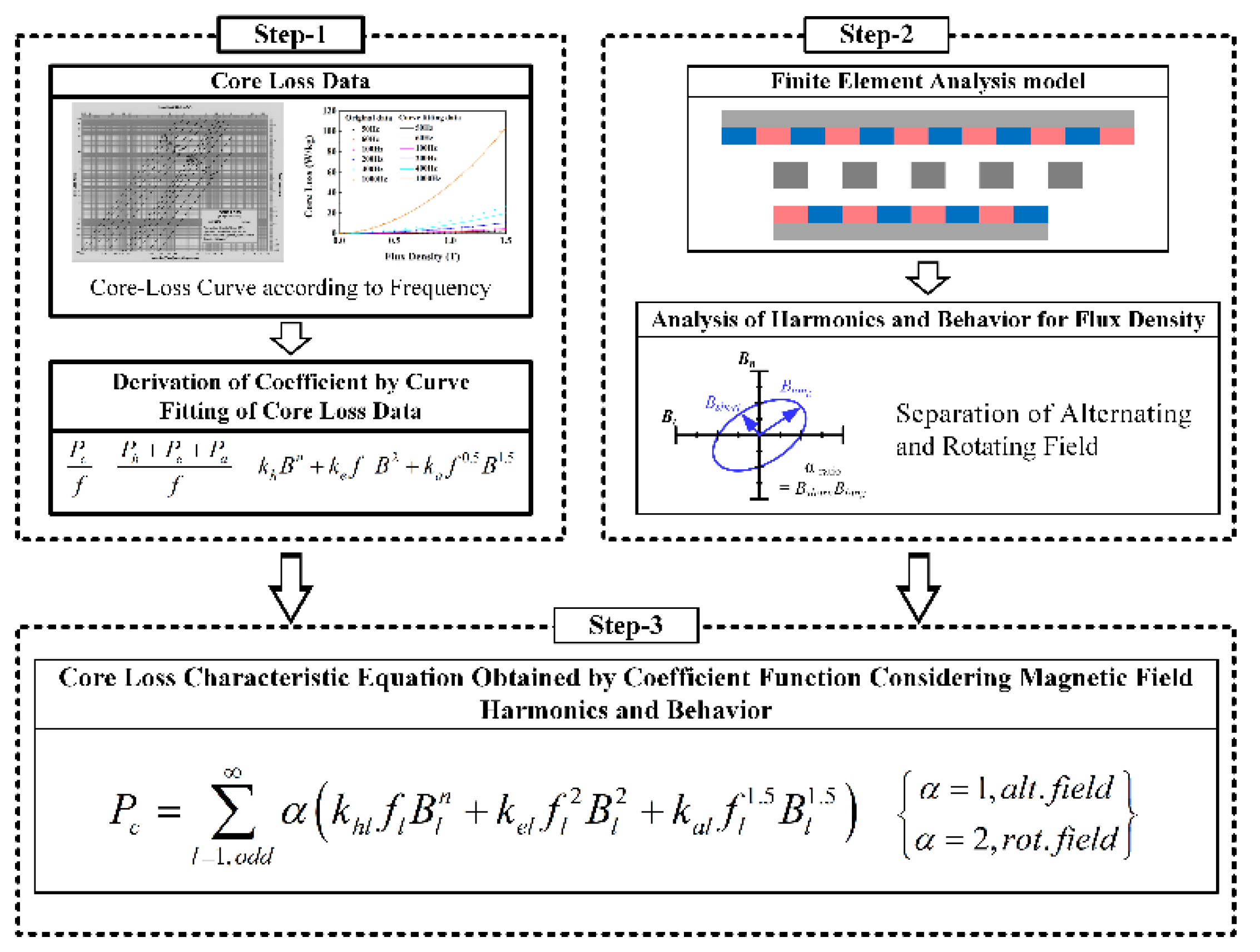
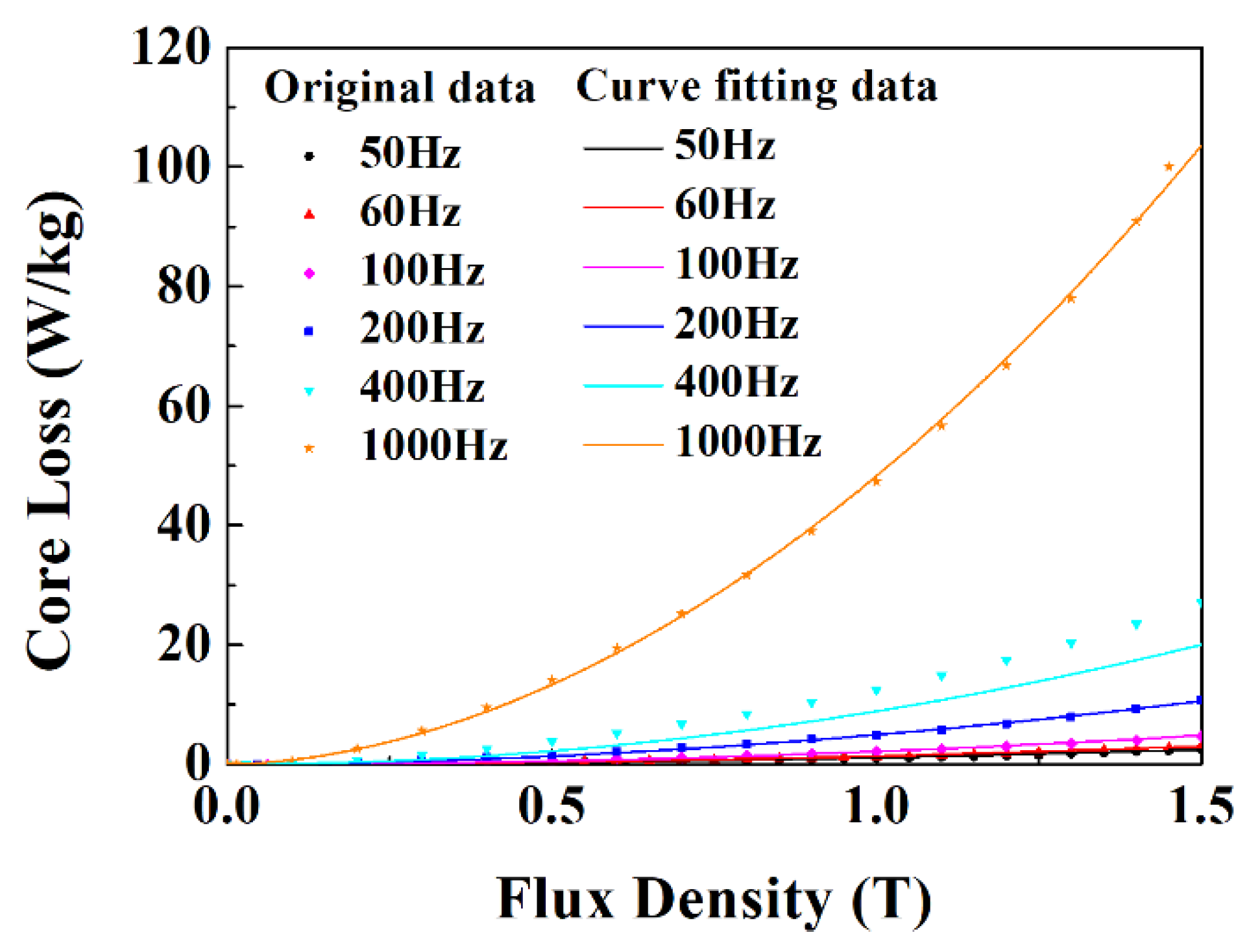
- Derivation of the core-loss curve fitting and core-loss coefficients according to the frequency of the core provided by the manufacturer.
- -
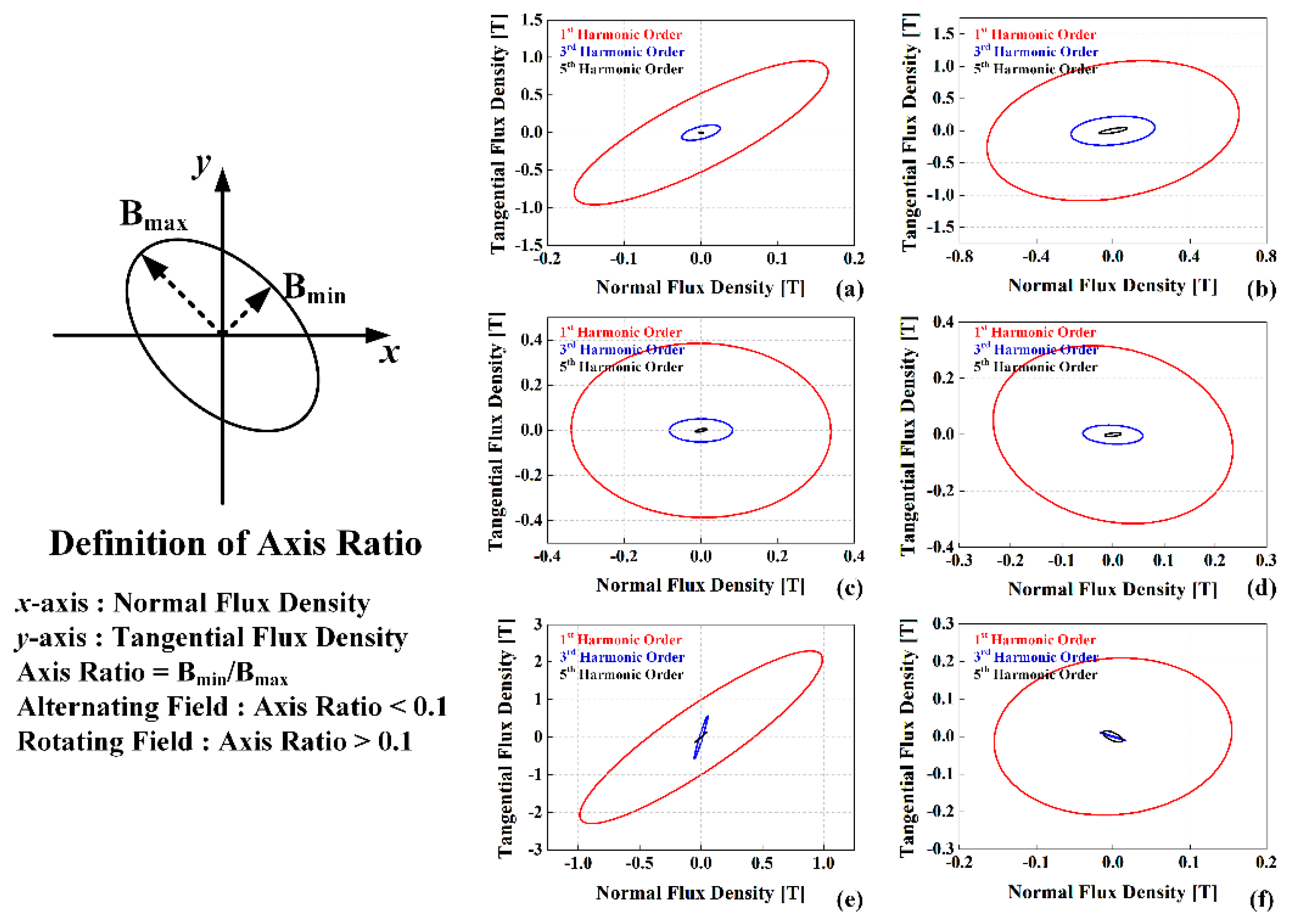
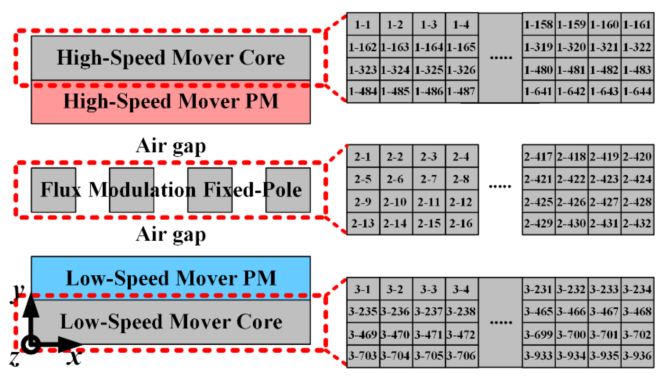
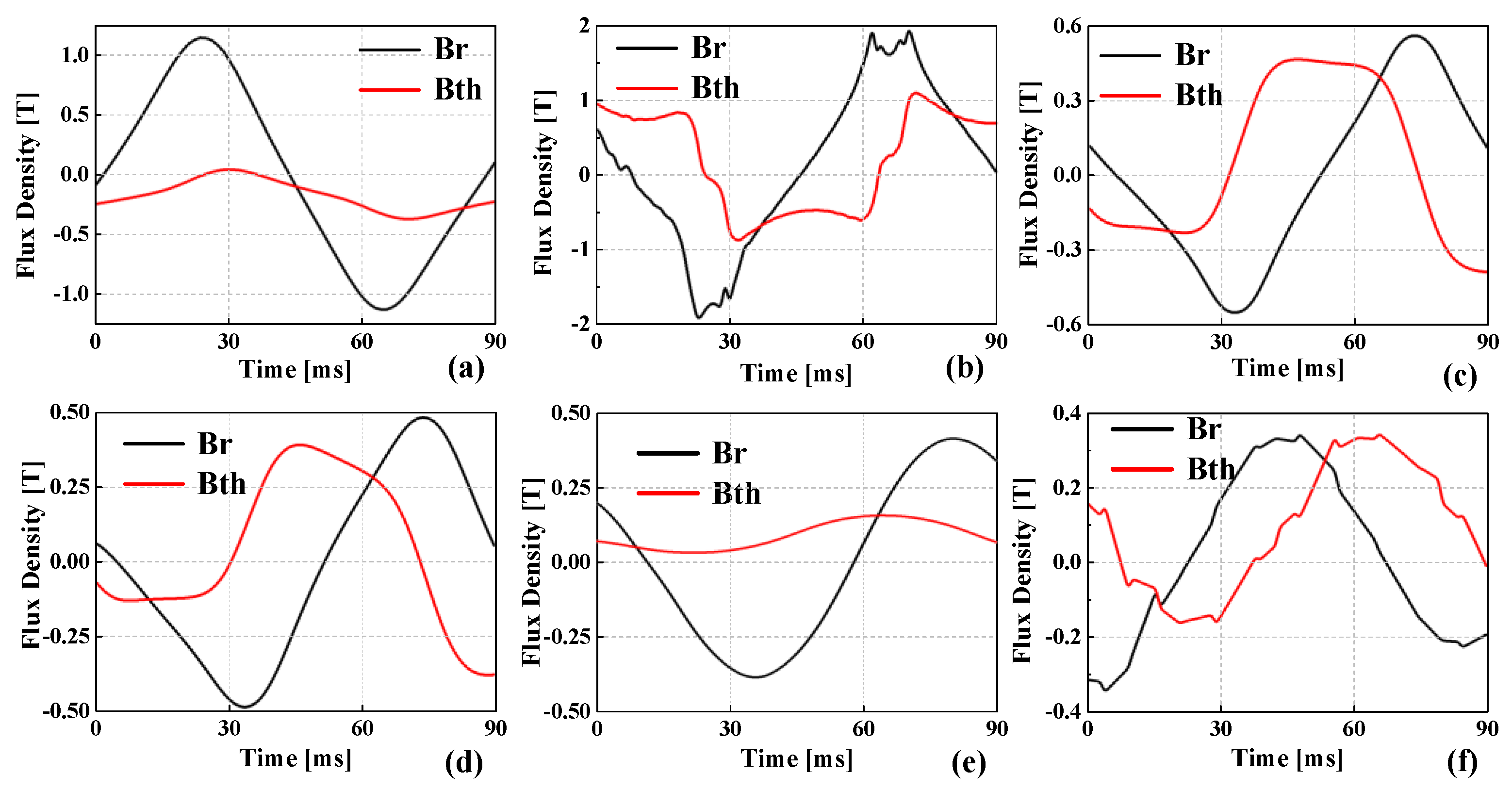
- Analysis of magnetic flux density and magnetic field behavior according to the core region.
- -
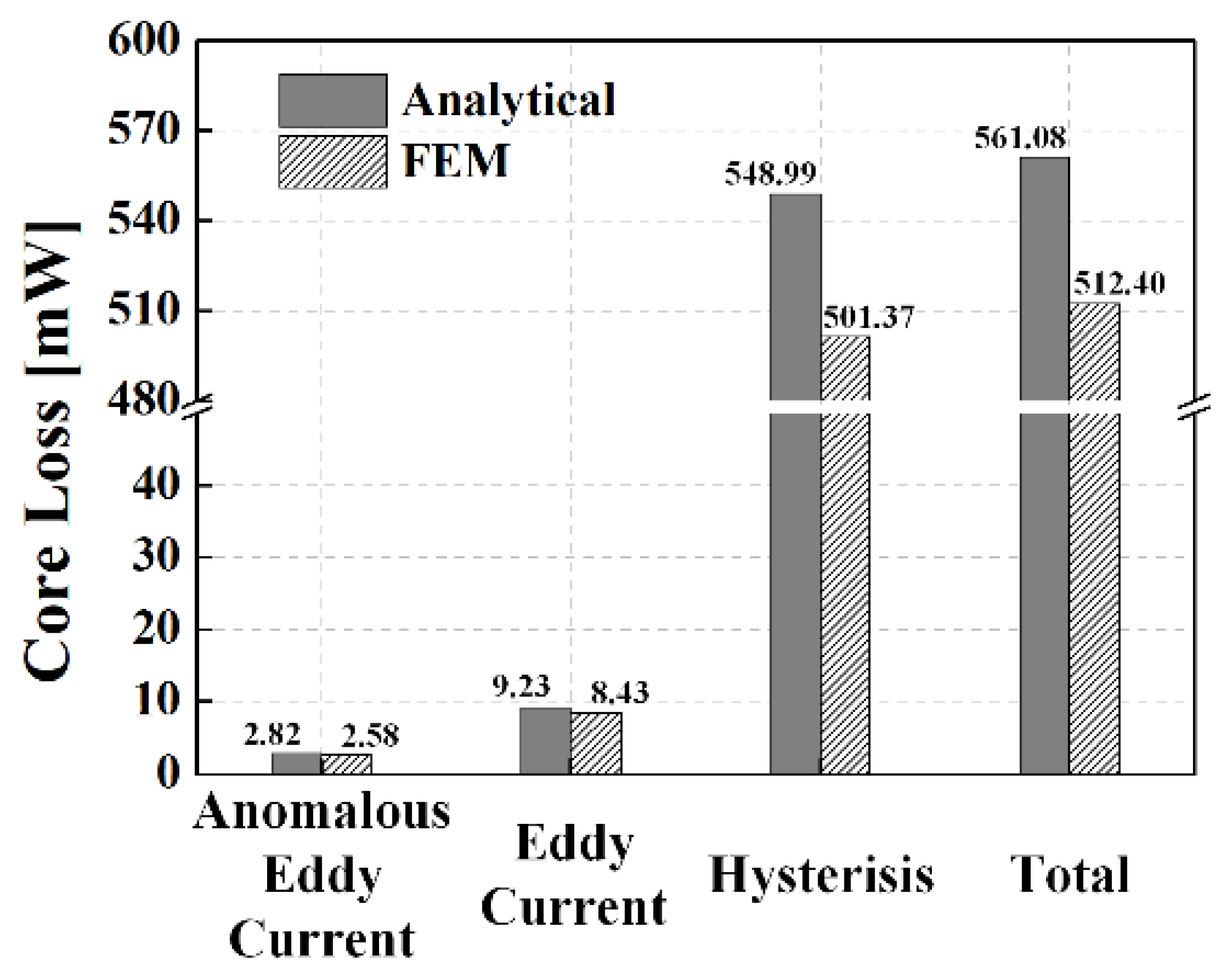
- Calculation of core-loss using modified Steinmetz equation of linear magnetic gears, taking into account magnetic field behavior and harmonics.
2. Core Loss Analysis of Linear Magnetic Gear
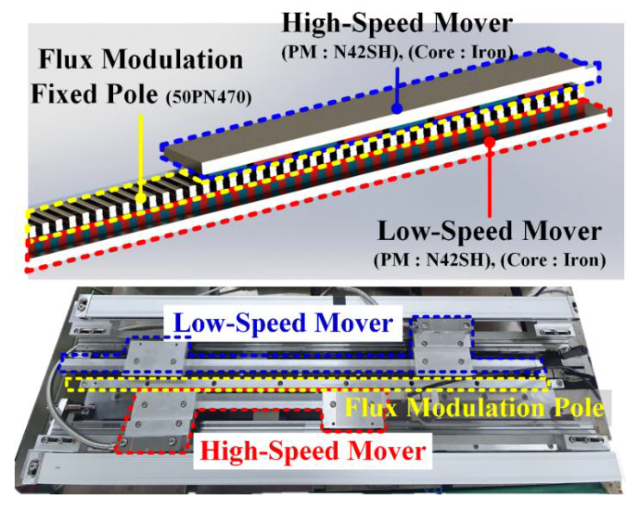
2.1. Analysis Model of Linear Magnetic Gear
2.2. Coreloss Characteristic Equation
2.3. Magnetic Field Behavior Analysis
3. Conclusions
Author Contributions
Funding
Institutional Review Board Statement
Informed Consent Statement
Conflicts of Interest
References
- Gardner, M.C.; Johnson, M.; Toliyat, H.A. Analysis of High Gear Ratio Capabilities for Single-Stage, Series Multistage and Compound Differential Coaxial Magnetic Gears. IEEE Trans. Energy Convers. 2019, 34, 665–672. [Google Scholar] [CrossRef]
- Shin, H.M.; Chang, J.H. Comparison of Radial Force at Modulating Pieces in Coaxial Magnetic Gear and Magnetic Gear Machine. IEEE Trans. Magn. 2018, 54, 1–4. [Google Scholar] [CrossRef]
- Tlalim, P.M.; Gerber, S.; Wang, R.-J. Optimal Design of an Outer-Stator Magnetically Geared Permanent Magnet Machine. IEEE Trans. Magn. 2016, 52, 1–10. [Google Scholar] [CrossRef]
- Frandsen, T.V.; Mathe, L.; Berg, N.I.; Holm, R.K. Motor Integrated Permanent Magnet Gear in a Battery Electrical Vehicle. IEEE Trans. Ind. Appl. 2015, 51, 1516–1525. [Google Scholar] [CrossRef]
- Park, E.J.; Jung, S.Y.; Kim, Y.J. Comparison of Magnetic Gear Characteristics Using Different Permanent Magnet Materials. IEEE Trans. Appl. Supercond. 2020, 30, 1–4. [Google Scholar] [CrossRef]
- Nam, H.; Ha, K.H.; Lee, J.J.; Hong, J.P.; Kang, G.H. A Study on Iron Loss Analysis Method Considering the Harmonics of the Flux Density Waveform Using Iron Loss Curves Tested on Epstein Samples. IEEE Trans. Magn. 2003, 39, 1472–1475. [Google Scholar] [CrossRef]
- Göbl, E.; Jungmayr, G.; Marth, E.; Amrhein, W. Optimization and Comparison of Coaxial Magnetic Gears with and without Back Iron. IEEE Trans. Magn. 2018, 54, 1–4. [Google Scholar] [CrossRef]
- Gardner, M.C.; Johnson, M.; Toliyat, H.A. Comparison of Surface Permanent Magnet Axial and Radial Flux Coaxial Magnetic Gears. IEEE Trans. Energy Convers. 2018, 33, 2250–2259. [Google Scholar] [CrossRef]
- Johnson, M.; Gardner, M.C.; Toliyat, H.A.; Ouyang, W.; Tschida, C. Design, Construction, and Analysis of a Large-Scale Inner Stator Radial Flux Magnetically Gear Generator for Wave Energy Conversion. IEEE Trans. Ind. Appl. 2018, 54, 3305–3314. [Google Scholar] [CrossRef]
- Zhu, Z.Q.; Ng, K.; Schofield, N.; Howe, D. Analytical Prediction of Rotor Eddy Current Loss in Brushless Machines Equipped with Surfaced-Mounted Permanent Magnets, Part II: Accounting for Eddy Current Reaction Field. In Proceedings of the Fifth International Conference in Electrical Machines and Systems, Shenyang, China, 18–20 August 2001; Volume 2, pp. 810–813. [Google Scholar] [CrossRef]
- Steinmetz, C. On the Law of Hysteresis. IEEE Trans. Am. Inst. Electr. Eng. 1892, 9, 1–64. [Google Scholar] [CrossRef]
- Yamazaki, K.; Fukishima, N. Iron Loss Model for Rotating Machine: Comparison between Bertotti’s Three Term Expression and 3-D Eddy Current Analysis. IEEE Trans. Magn. 2010, 46, 3121–3124. [Google Scholar] [CrossRef]
- Kim, C.W.; Koo, M.M.; Kim, J.M.; Ahn, J.H.; Hong, K.Y.; Choi, J.Y. Core Loss Analysis of Permanent Magnet Synchronous Generator with Slotless Stator. IEEE Trans. Appl. Supercond. 2018, 28, 1–4. [Google Scholar] [CrossRef]
- Enokizono, M.; Suzuki, T.; Sievert, J.; Xu, J. Rotational Power Loss of Silicon Steel Sheet. IEEE Trans. Magn. 1990, 26, 2562–2564. [Google Scholar] [CrossRef]
- Kim, C.W.; Kim, J.M.; Seo, S.W.; Ahn, J.H.; Hong, K.Y.; Choi, J.Y. Core Loss Analysis of Permanent Magnet Linear Synchronous Generator Considering the 3-D Flux Path. IEEE Trans. Magn. 2018, 54, 1–4. [Google Scholar] [CrossRef]
- Woo, J.H.; Kim, C.W.; Bang, T.K.; Lee, S.H.; Lee, K.S.; Choi, J.Y. Experimental Verification and Electromangetic Characteristic Analysis of Permanent Magnet Linear Oscillating Actuator Using Semi 3D Analysis Technique with Corrected Stacking Factor. Trans. Appl. Supercond. 2020, 30, 1–4. [Google Scholar] [CrossRef]


| Parameters | Value |
|---|---|
| High-speed mover length | 322 mm |
| Low-speed mover length | 702 mm |
| Thickness of low-speed core | 10 mm |
| Thickness of low-speed mover permanent magnet | 8 mm |
| Thickness of air-gap | 2 mm |
| Thickness of flux modulation fixed-pole | 9 mm |
| Thickness of high-speed core | 10 mm |
| Thickness of high-speed mover permanent magnet | 8 mm |
| High-speed mover number of poles | 8 |
| Low-speed mover number of poles | 46 |
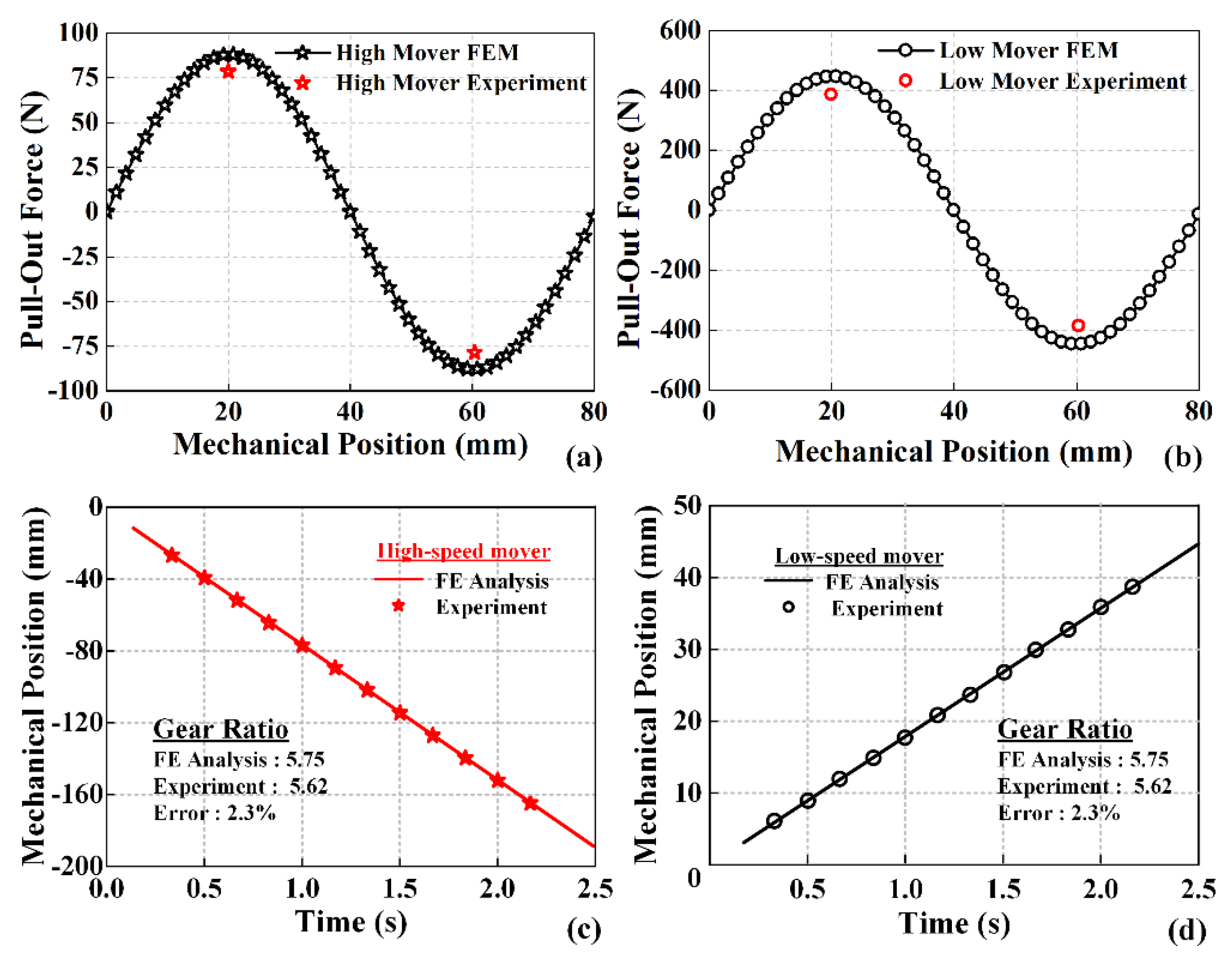
| Moving speed of high-speed mover | 1 m/s |
| Gear ratio | 5.75 |
| Frequency | |||
|---|---|---|---|
| 50 [Hz] | 0.018721 | 0.000458748 | 1.39192 × 10⁻⁵ |
| 60 [Hz] | 0.0188188 | 0.000458518 | 1.38762 × 10⁻⁵ |
| 100 [Hz] | 0.0216049 | 0 | 0 |
| 200 [Hz] | 0.0150994 | 0.000461586 | 1.56562 × 10⁻⁵ |
| 400 [Hz] | 0.0162534 | 0.000465451 | 1.49788 × 10⁻⁵ |
| 1000 [Hz] | 0.0217835 | 0.000391975 | 1.4123 × 10⁻⁵ |
| Parameters | Modified Steinmetz Core-Loss | FEM Core-Loss |
|---|---|---|
| Input Power [W] (high-speed mover) | 58.4 | 58.1 |
| Output Power [W] (low-speed mover) | 54.65 | 54.41 |
| Solid Loss [W] | 3.18 | |
| Core-Loss [mW] | 561.08 | 512.405 |
| Efficiency [%] | 93.59 | 93.64 |
Publisher’s Note: MDPI stays neutral with regard to jurisdictional claims in published maps and institutional affiliations. |
© 2021 by the authors. Licensee MDPI, Basel, Switzerland. This article is an open access article distributed under the terms and conditions of the Creative Commons Attribution (CC BY) license (https://creativecommons.org/licenses/by/4.0/).
Share and Cite
Lee, J.-I.; Shin, K.-H.; Bang, T.-K.; Kim, K.-H.; Hong, K.-Y.; Choi, J.-Y. Core-Loss Analysis of Linear Magnetic Gears Using the Analytical Method. Energies 2021, 14, 2905. https://doi.org/10.3390/en14102905
Lee J-I, Shin K-H, Bang T-K, Kim K-H, Hong K-Y, Choi J-Y. Core-Loss Analysis of Linear Magnetic Gears Using the Analytical Method. Energies. 2021; 14(10):2905. https://doi.org/10.3390/en14102905
Chicago/Turabian StyleLee, Jeong-In, Kyung-Hun Shin, Tae-Kyoung Bang, Kyong-Hwan Kim, Key-Yong Hong, and Jang-Young Choi. 2021. "Core-Loss Analysis of Linear Magnetic Gears Using the Analytical Method" Energies 14, no. 10: 2905. https://doi.org/10.3390/en14102905
APA StyleLee, J.-I., Shin, K.-H., Bang, T.-K., Kim, K.-H., Hong, K.-Y., & Choi, J.-Y. (2021). Core-Loss Analysis of Linear Magnetic Gears Using the Analytical Method. Energies, 14(10), 2905. https://doi.org/10.3390/en14102905