In this section, the outline of the five case studies is described. These case studies differ on the quantities of the utilized gases for the syntheses and on the produced chemical (methane/methanol). The case studies are:
The selected scenarios want to cover the short-, medium-, and long-term technology deployment horizon and to provide useful information in order to reduce the relevant costs when moving towards the large deployment of the proposed technological option. In particular, the Cases 1, 2, and 4 are adopted because they actually present the medium- to long-term capacities required to deploy the proposed technological option. On the other hand, Cases 3 and 5 represent a shorter-term demonstration of that technological option to move towards decarbonization of steelmaking.
After the description of the case studies in
Section 3.1, the overall process scheme is presented in
Section 3.2 that includes the aforementioned systems (gas cleaning, hydrogen production, methane, and methanol synthesis) as well as the power plant. A gas cleaning strategy is proposed in
Section 3.3 based on the possible contained impurities, whereas
Section 3.4 and
Section 3.5 involve the description of the methanol and methane synthesis processes and the followed AspenPlus
TM modelling methodology. Sensitivity analyses on crucial modelling approaches and operating parameters are conducted on both processes. Finally,
Section 3.6 includes the description of PEM electrolysis for the production of renewable hydrogen.
3.1. Case Studies Description
The integration of methane and methanol synthesis is evaluated for the previously described scenarios considering a steelmaking plant of medium size with an annual steel production of about 6 MT. The different case scenarios are evaluated in terms of carbon conversion, product yields, hydrogen requirements and consumption, electrolysis demands, as well as overall efficiency of the process. For the cases where power is produced, it is assumed that a gas-fired boiler is in operation within the plant [
16].
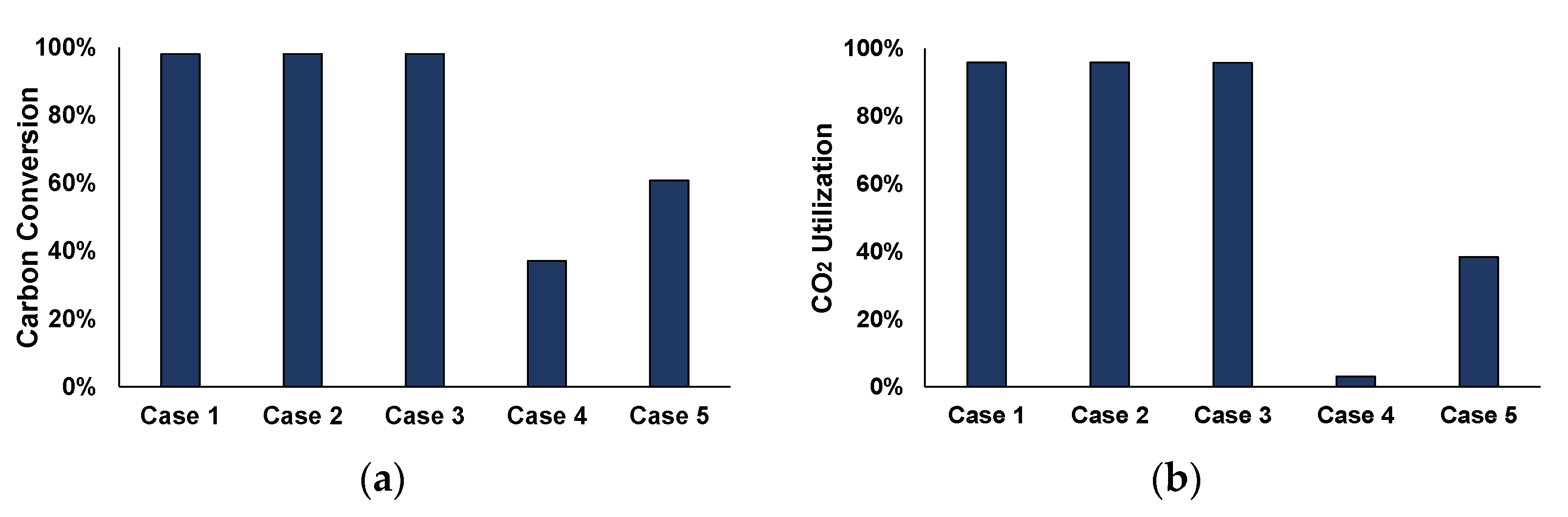
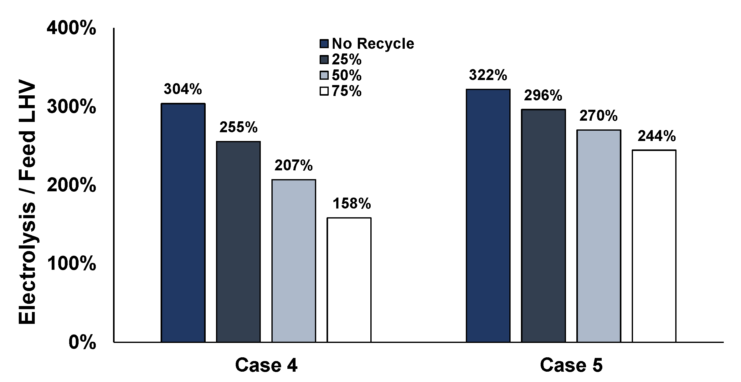
Figure 1,
Figure 2,
Figure 3,
Figure 4 and
Figure 5 depict the different flowrates and utilization factors of the steelworks off-gases.
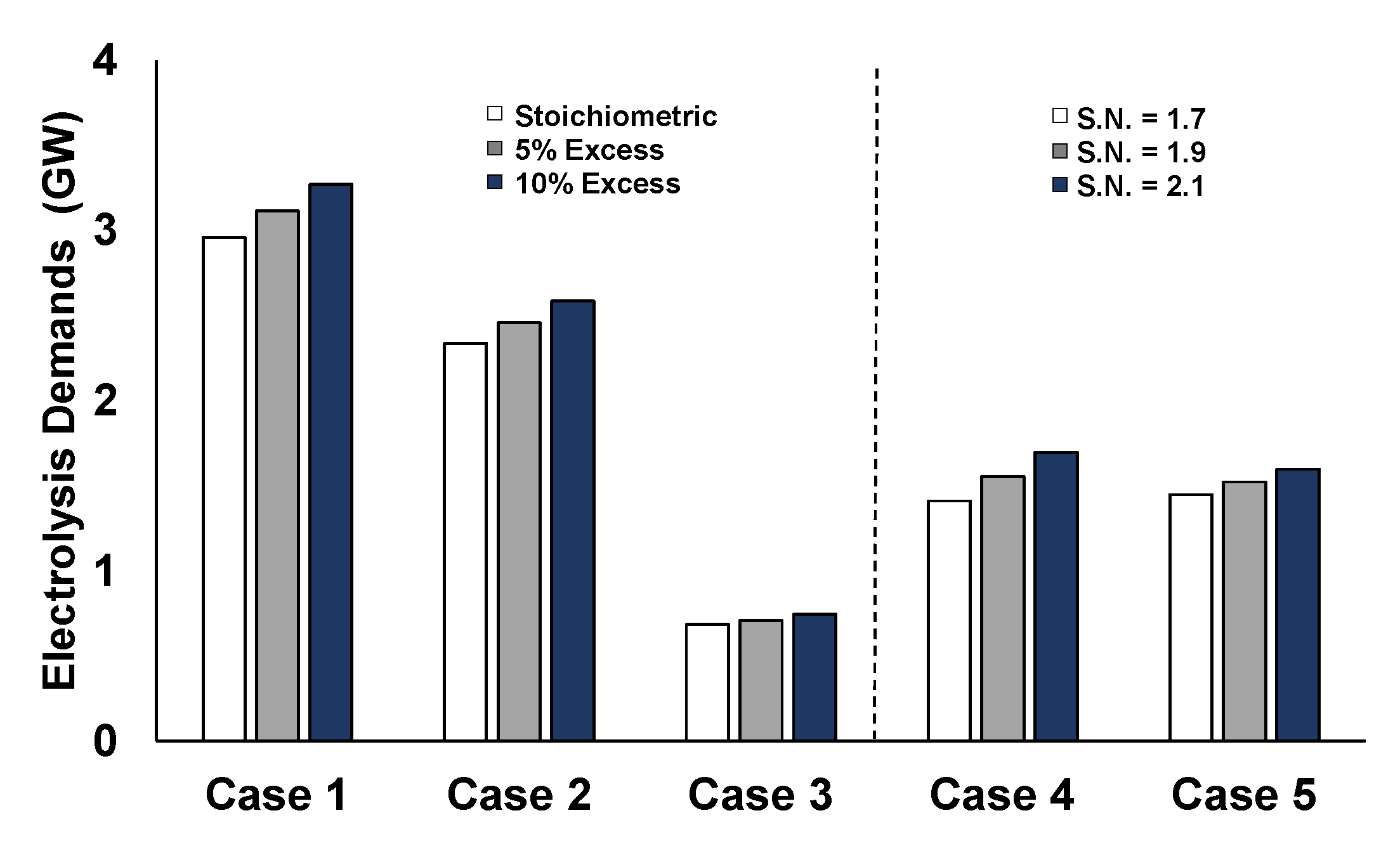
The first case represents the utilization of the entire available amount of the three off-gases for the production of methane. Renewable hydrogen is added in basic stoichiometric ratio to produce methane. This represents a boundary scenario for the utilization of the steelwork gases, which is restrictive in terms of hydrogen flows and electrolysis power requirements.
- 2.
Methanation of 80% of the available by-product gases and the remaining fraction used in the power plant
The steelworks off-gases have generally various uses within the steel plant and the main one is for the production of electrical power. However, in this scenario, 80% of the total amounts of the gases are used for the production of methane with the addition of renewable hydrogen and the other fraction is sent to the power plant. Before the methanation process, the enrichment step serves as mixing/upgrading process before entering the power plant. A part of the COG is dispatched directly to methane synthesis, due to its higher hydrogen content compared to the other gases. Although, the CH4 content of COG could have a negative impact in methanation activity, the amount of available COG is relatively small compared to the total utilized gases, reducing significantly the methane quantities (i.e., <1%) in the reactor inlet of the methanation cases (i.e., after the H2 addition).
- 3.
Methanation of specific amounts of the by-product gases in order to replace the natural gas demands of the plant
This case investigates the possibility of valorizing the steelworks off-gases for the replacement of the internal steelworks needs of natural gas—assuming an overestimated case of approximately 50,000 Nm
3/h internal natural gas demands for a 6 MT/year steel plant [
12]. The remaining portion of the gases is combusted in the power plant.
- 4.
Methanol synthesis of 80% of the by-product gases and the rest goes to the power plant
Similar with Case 2, 80% of the amounts of the gases are used for methanol production with the addition of renewable hydrogen, whereas the remaining portion is used in the power plant.
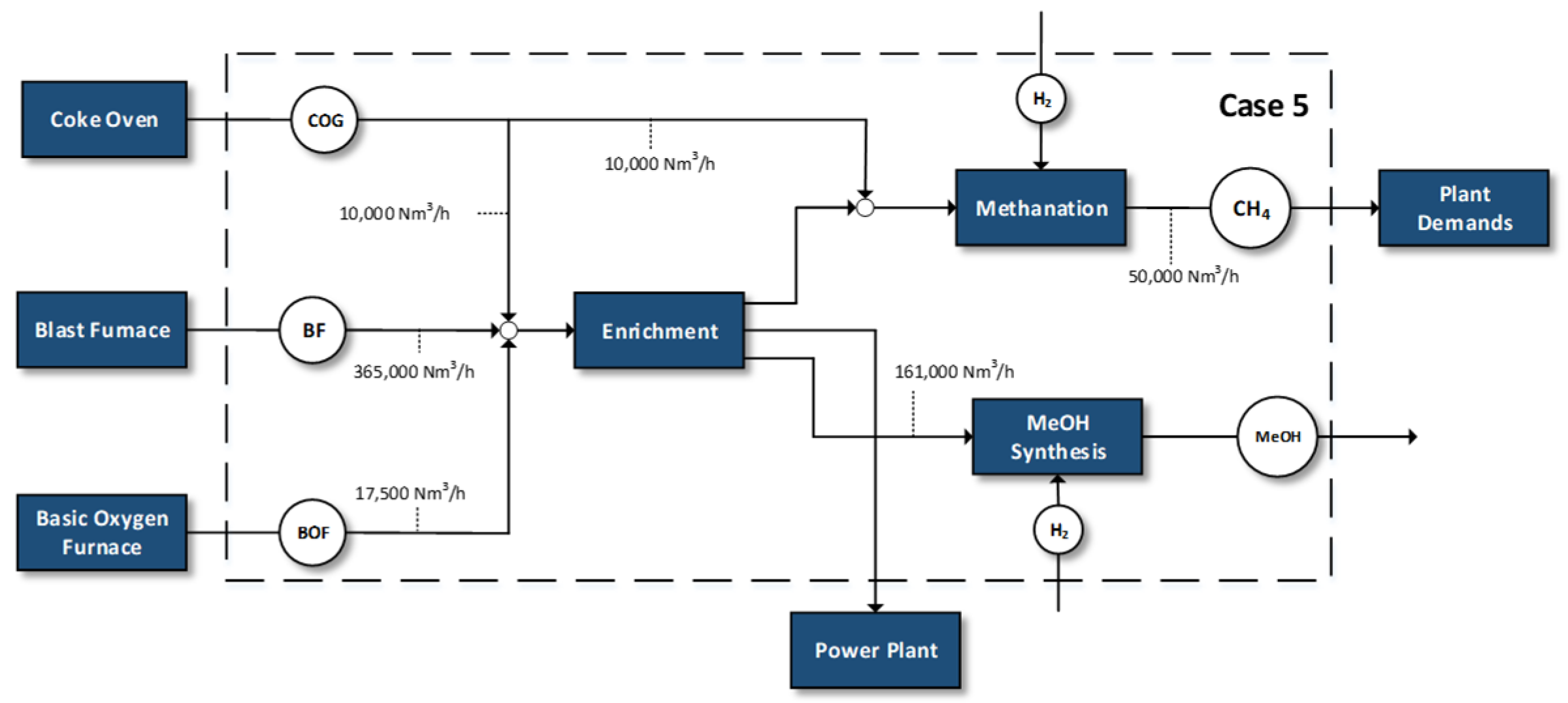
- 5.
Methanation of specific amounts of the by-product gases in order to replace the natural gas demands and the production of significant quantities of MeOH
Case 5 represents the most integrated valorization scheme for steel gases for the simultaneous production of methane and methanol. After the enrichment step, half of the amount employed in Case 4 is used for methanol production and another part is used for the replacement of the industry’s natural gas demands. Finally, a part of the gases is sent to the power plant.
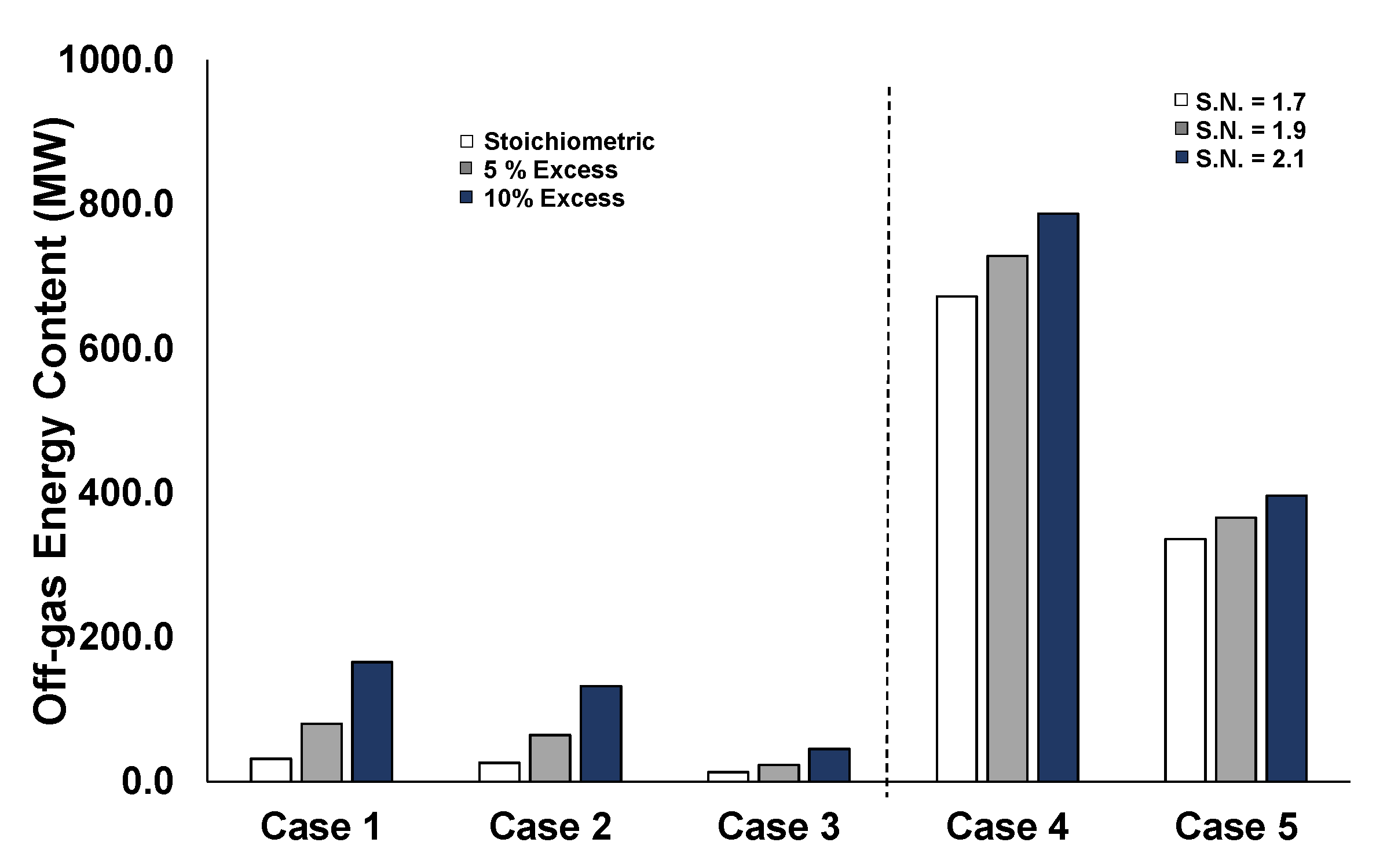
Figure 6 shows a comparison of the energy content of the mixed feedstock of Case 1 with respect to the energy content of the other cases, by highlighting the different off-gases contribution. In the first scenario, BFG comprises 73% of the total energy content of the feed stream to the syntheses processes, due to the larger used flowrate, whereas COG, although in lower quantity (20,000 Nm
3/h compared to 365,000 Nm
3/h of the BFG; 5% of the total amount) contains a significant portion of the overall energy content (19%). This indicates a higher energy content per m
3, due to the contained CH
4 and H
2 and the lower CO
2 and N
2 contents in the COG feedstock. Regarding the energy contents of the feedstock used in the different scenarios, Cases 2 and 4 use the same feed quantities for the production of chemicals (81% of the energy compared to Case 1). Case 3 represents the feedstock energy content for the replacement of the natural gas demand of the plant, while Case 5 is a combined case for the replacement of natural gas as well as for methanol synthesis (33% and 70%, respectively).
3.2. Integration Options of CH4/MeOH Syntheses Concepts into Steelworks
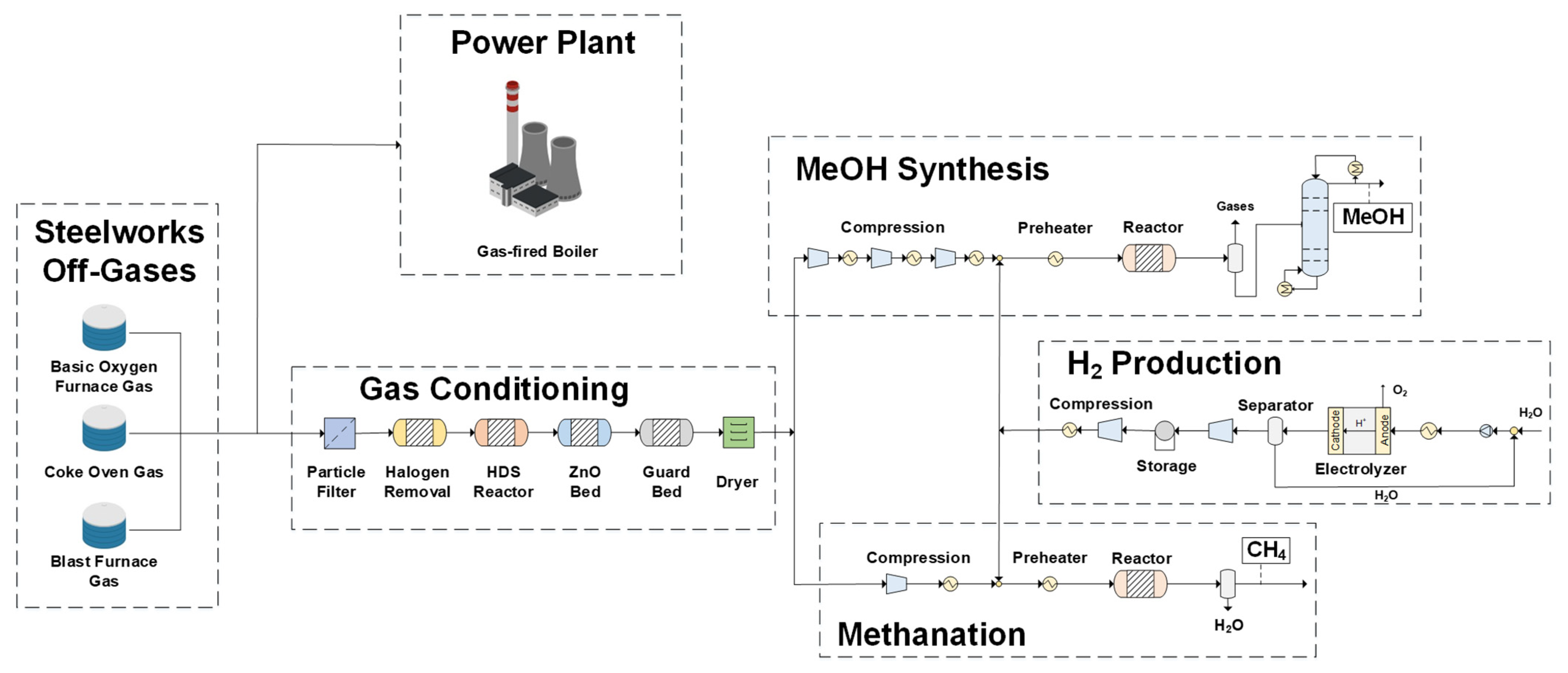
Figure 7 shows the overall process flowsheet that includes the major sections of the proposed concept: gas conditioning, methane production, methanol synthesis, hydrogen production, and the power plant (for the cases where power is produced).
The mixture of the steelworks off-gases, after an ad hoc conditioning for removal of unwanted impurities, is fed either to the methanol synthesis or to the methanation section. For the methanol synthesis, the feed gas undergoes compression in three stages in order to reduce the associated compression ratio costs; intermediate cooling between the stages is provided. Afterwards, hydrogen is added to reach the required stoichiometric number and the inlet mixture is preheated before inserted to the synthesis reactor. The produced mixture is separated using a flash separator into the liquid (mainly methanol and water) and gaseous products that consist of the unreacted hydrogen and the rest of the initial feedstock. The last step is the purification of the methanol product in a distillation column, which removes the contained product water.
The first step for methanation requires compression only in one step, since methanation takes place at low pressures (<10 bar). Renewable hydrogen is added to achieve the required stoichiometric ratio and the inlet feed is preheated and directed to the reactor. A flash separator is also used to separate the gaseous products from the produced liquid water.
Table 2 depicts the assumptions that refer to the overall process flowsheet simulations. The off-gases composition reported in
Table 1 is taken as the starting point of the subsequent flowsheet simulations.
3.3. Impurities and Gas Conditioning
The three steelwork off-gases undergo different cleaning steps in order to remove the contained, unwanted components before being stored in gas holders. Typical gas cleaning steps involve dust removal, cooling, scrubbing (for ammonia and BTX removal), and demistering [
19,
25]. After the initial steps, additional gas cleaning is required to protect the methane [
26] and methanol [
27] syntheses catalysts.
As shown in
Table 1, several sulfur-containing compounds can be found in the steelworks off-gases, which cause corrosion and poisoning of Cu-based catalysts. Other common impurities include nitrogen-containing species such as ammonia or hydrogen cyanide. At the high temperatures of the steel production processes, nitrogen oxides NO
x can be formed, which have to be removed from the exhaust gases, whereas at lower temperatures, NH
3 can be adsorbed at catalyst sites, reducing the catalyst activity [
28]. Halogens (HCl, HF, and HBr) are also contained in the off-gases and are known to cause corrosion and poison catalysts. In particular, experimental works have shown that HCl poisoning could cause loss of the active surface area of the catalyst and promote sintering of the copper crystallites [
27]. Furthermore, additional reactions could occur between HCl and other contaminant-forming species such as NH
4Cl and NaCl, which when condensed, could cause fouling and create deposits in cooler downstream pipes and equipment [
29,
30]. Finally, trace elements and heavy metals are also contained in the off-gases due to the diverse nature of the feedstocks. Besides corrosion problems, other trace elements pose a threat to human health and the environment. The distribution and partitioning of these contaminants play an important role on the undertaken cleaning strategy. For example, particle filters could be used for solid particles, but if those compounds appear in the gaseous phase, more advanced cleaning efforts should be employed, such as solid sorption. Whether a trace element appears in the gas or particulate phase and in which form, depends on following factors [
31]:
how the trace element resides in the incoming material,
temperature and pressure,
oxidizing or reducing conditions,
presence of halogens, such as chlorine,
presence of compounds that can act as sorbents, such as calcium.
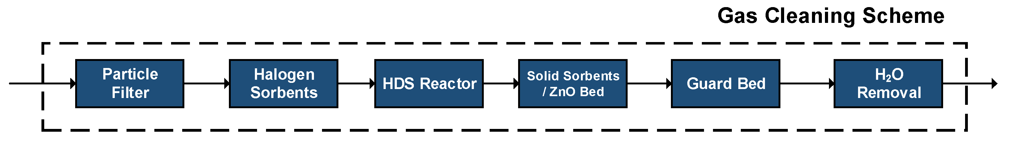
Based on the contained impurities,
Figure 8 depicts the proposed off-gases cleaning strategy. Each of the cleaning steps targets aims at a specific impurity group. However, possible interactions between an impurity and a precedent/succeeding step cannot be ruled out.
A first step is devoted to the removal of any contained solid particles through fine filters. Afterwards, the contained halogens (HCl, HF, etc.) are removed using inexpensive sorption materials such as NaHCO
3 (Nahcolite) or Trona (Na
2CO
3-NaHCO
3-2H
2O) [
28]. For instance, in the case of nahcolite, HCl is removed in the form of NaCl, whereas H
2O and CO
2 are also formed, according to the following reaction:
Regarding the sulfur-containing compounds, H
2S is more easily removed at ppb levels with respect to other sulfur species. A common strategy consists in converting organic sulfur compounds to H
2S and then employing adsorption technologies for the deep removal of H
2S [
32]. The avoidance of acid gas removal process, such as Selexol
TM or Rectisol
TM, despite their efficiency in reducing H
2S to ppm levels, lies within their affinity to physically absorb CO
2, which should otherwise be used as feedstock for the production of methanol/methane [
26].
At the hydrodesulfurization (HDS) reactor, organic sulfur compounds and COS are converted to H
2S through the addition of hydrogen. The usual employed catalysts are based on cobalt and nickel. A possible reaction network for the conversion to hydrogen sulfide is the following [
33]:
Afterwards, a sorption bed containing metal oxides, such as CaO and ZnO, can be used for the removal of H
2S. For the case of ZnO, H
2S is removed in the form of ZnS [
34]:
It is an exothermic process, conducted at T < 250 °C and as shown in the reaction stoichiometry, the reaction equilibrium is not affected by pressure, whereas the inlet content of water could affect the H
2S removal efficiency. Studies have shown that H
2S can be effectively removed at ppb levels employing the ZnO strategy [
34,
35]. However, due to the contained CO and CO
2, additional reactions could occur, with a consequent deterioration of the H
2S removal efficiency [
34,
36].
Finally, a guard bed is placed, containing nickel or other inexpensive material to protect the subsequent synthesis units. It restricts impurities that could have escaped from the former gas cleaning steps and acts as a final protection before the production of chemicals. In addition, the gases are dried to remove the contained water to avoid condensation during compression and/or the promotion of unwanted side-reactions.
3.6. Hydrogen Production
Due to the composition of the steelworks off-gases, hydrogen addition is required in order to reach certain stoichiometric ratios and improve the efficiency of methane and methanol syntheses. In order to obtain both economic and environmental advantages, hydrogen needs to be produced in an environmentally friendly way, i.e., by exploiting renewable sources. In this work, the adopted process is water electrolysis fed by renewable energy.
During water electrolysis, the water molecules are split into hydrogen and oxygen by means of electricity. There are three main electrolysis processes, each one differing on the operating principles and conditions: alkaline exchange membrane (AEM), proton exchange membrane (PEM) and solid oxide electrolysis (SOE) [
53]. In the present work, PEM electrolysis is considered as the option for renewable hydrogen production, since it is an already established technology, it is used in large-scale industrial applications and it is not sensitive to the fluctuations in power supply, such as in the case of renewable energy sources [
24].
For the calculation of the power requirements, an AspenPlus
TM PEM electrolysis model has been developed. The model incorporates the following main reactions occurring in the two PEM sections:
In addition, further phenomena taking place inside a PEM electrolysis module are also considered such as hydrogen and oxygen permeations [
54,
55] and water diffusion [
55,
56], which are estimated in ad hoc configured calculator blocks. Highly pure hydrogen is assumed to be produced (<99.9 vol.%), and the overall electrical energy consumption for the stack is 54.8 kWh/kg H
2. The produced hydrogen is stored into pressurized vessels and compressed to achieve the conditions required for the syntheses units.
A detailed description of the PEM electrolysis model, as well as of other renewable hydrogen production technologies that are considered possible solutions for the enrichment of steelworks off-gases, is included in another publication by the authors [
57].


 ,
, 


