Article

Effects of Evaporator and Condenser in the Analysis of Adsorption Chillers

Department of Mechanical Engineering, Sejong University, Seoul 05006, Korea
*
Author to whom correspondence should be addressed.
Energies 2020, 13(8), 1901; https://doi.org/10.3390/en13081901
Submission received: 11 March 2020 / Revised: 31 March 2020 / Accepted: 11 April 2020 / Published: 13 April 2020
(This article belongs to the Special Issue Solar Thermal Energy Conversion and Storage)

Abstract

:
In a survey of the literature from the last 20 years, 20% of the numerical models used to analyze the performance of adsorption chillers assumed the evaporator and condenser were ideal, with a fixed evaporation temperature and condenser temperature, and ignored interactions between the adsorption bed and evaporator/condenser. Even when the interaction with the evaporator and condenser was included, the other 80% of studies modeled the adsorption bed based on the LPM (lumped parameter method), which ignores the geometry effect and contact resistance of the bed, and thus reduces the accuracy of the analysis. As a consequence, these earlier numerical studies overestimated the system performance of the adsorption chiller. In this study, we conducted a refined numerical approach which avoids these limitations, producing estimates in close agreement with experimental results. Compared with our approach, the models with ideal treatment of evaporator and condenser overestimated COP (coefficient of performance) and SCP (specific cooling power) by as much as 16.12% and 24.64%, respectively. The models based on LPM overestimated COP and SCP by 22.82% and 11.28%, compared to our approach.

1. Introduction

Demand for cooling has rapidly increased due to global warming and economic development. There are many types of refrigerator systems that can be employed to address this demand. Among them, the vapor compression refrigerator has been most commonly used. However, its operation negatively impacts the environment and consumes an excessive amount of electric power. As a result, many researchers have focused on the development of eco-friendly refrigeration systems. Among these, heat-driven refrigerators, such as absorption, desiccant, and adsorption cooling system, have been highly attractive.
The adsorption chiller operates using reversible adsorption and desorption processes, in a cycle of preheating, heating, pre-cooling, and cooling. During the pre-heating process, the sorption bed is isolated from both the condenser and the evaporator by closing the connecting valves. Because desorption is an endothermic process, heat must be supplied to maintain the desorption process. When the pressure of the sorption bed reaches that of the condenser, the valve connecting the sorption bed and the condenser is opened and the desorbed refrigerant flows to the condenser. During the pre-cooling process, the sorption bed is again isolated by closing the connecting valves. Because of the exothermic nature of adsorption, the heat needs to be removed by the cold heat source. When the pressure of the sorption bed reaches that of the evaporator, the valve connecting to the evaporator is opened and the evaporated refrigerant vapor moves towards the sorption bed.
To understand the adsorption chiller process in more detail, a number of researchers have been conducting studies, investigating adsorbents [1,2,3], the geometry of the heat exchanger [4,5,6], advanced cycle [7,8,9,10], and operating conditions [11,12,13].
From the literature survey, the research target of numerical analyses was confined to the adsorption bed due to the limitation in numerical analysis. From a literature survey of the last 20 years, 20% of the published papers were found to belong to this category. Although they rigorously modeled the adsorption bed, they did not include modeling of the evaporator or condenser.
Adsorption beds have the same role as the compressor in a conventional refrigerator. Due to the reversibility of adsorption and desorption processes, outlet temperature is unstable and fluctuates [14,15]. For accurate prediction of coefficient of performance (COP), the change of chilled-out temperature of the evaporator should be included in the modeling, and the analysis of evaporators and condensers is important.
Previous numerical studies [1,3,5,6] covered many interesting issues and practical improvement of adsorption cooling systems. However, there has been no report on the impact of assumption on the evaporator and condenser. The isotherm of the sorbent is a function of pressure and temperature [3]. Thus, the idealized evaporator temperature distorts the evaluation of the system performance.
The other 80% of published papers included modeling of the evaporator or condenser. However, modeling of the adsorption bed, which is the most crucial component in the adsorption chiller, was based on the lumped parameter method (LPM), i.e., the adsorption bed, and the evaporator and condenser were modeled by assuming there was no spatial variation. Thus, the LPM-based analyses cannot include the effects of geometric features and the interaction between the sorbent material and the metallic finned tube. Note that geometric factors such as fin height, fin spacing, tube diameter, and thickness, are highly influential on the system performance, thus plenty of previous studies have conducted the optimization of geometric factors. The LPM, which assumes no special variation, affirmatively deteriorates the accuracy of the analysis.
Most of LPM-based analyses were for macrosystems such as recovery cycles and multi-stages. They have advantages in understanding system arrangement and the effect of each composition. However, essentially, LPM-based analyses suffer from low accuracy due to the excessive simplification of the adsorption bed, which is the most important part of adsorption cooling system.
In this study, we numerically analyzed an adsorption chiller with a SWS-1 L + water working pair based (1) on a rigorous CFD simulation for the adsorption bed, and (2) also including the evaporator and condenser. Model validity was checked by the comparison with experiments. For the present approach and the previous approaches, a close examination on the accuracy of system performance prediction was conducted. This approach provided detailed information over time and space and also enabled a much closer estimate of system performance.

2. Numerical Method

2.1. Mathematical Model

Figure 1 and Figure 2 show the schematics of the 2-bed adsorption chiller, and the current numerical model, respectively. The numerical model includes the following assumptions.
(1)
The particles in the adsorption bed are all spherical with a uniform size and porosity.
(2)
Thermal equilibrium between the adsorbed and vapor phases is assumed.
(3)
A two-dimensional (2D) axisymmetric model is assumed.
(4)
Refrigerant vapor is an ideal gas and the adsorbed phase is liquid.
(5)
There is no heat loss through the chamber wall and the effect of radiation is negligible.
(6)
The thermo-physical properties of the thermal fluid, tube, fins, dry adsorbent, adsorbate liquid, and gas are constant, except for the density of the adsorbate gas.

2.2. Energy and Mass Balance Equations

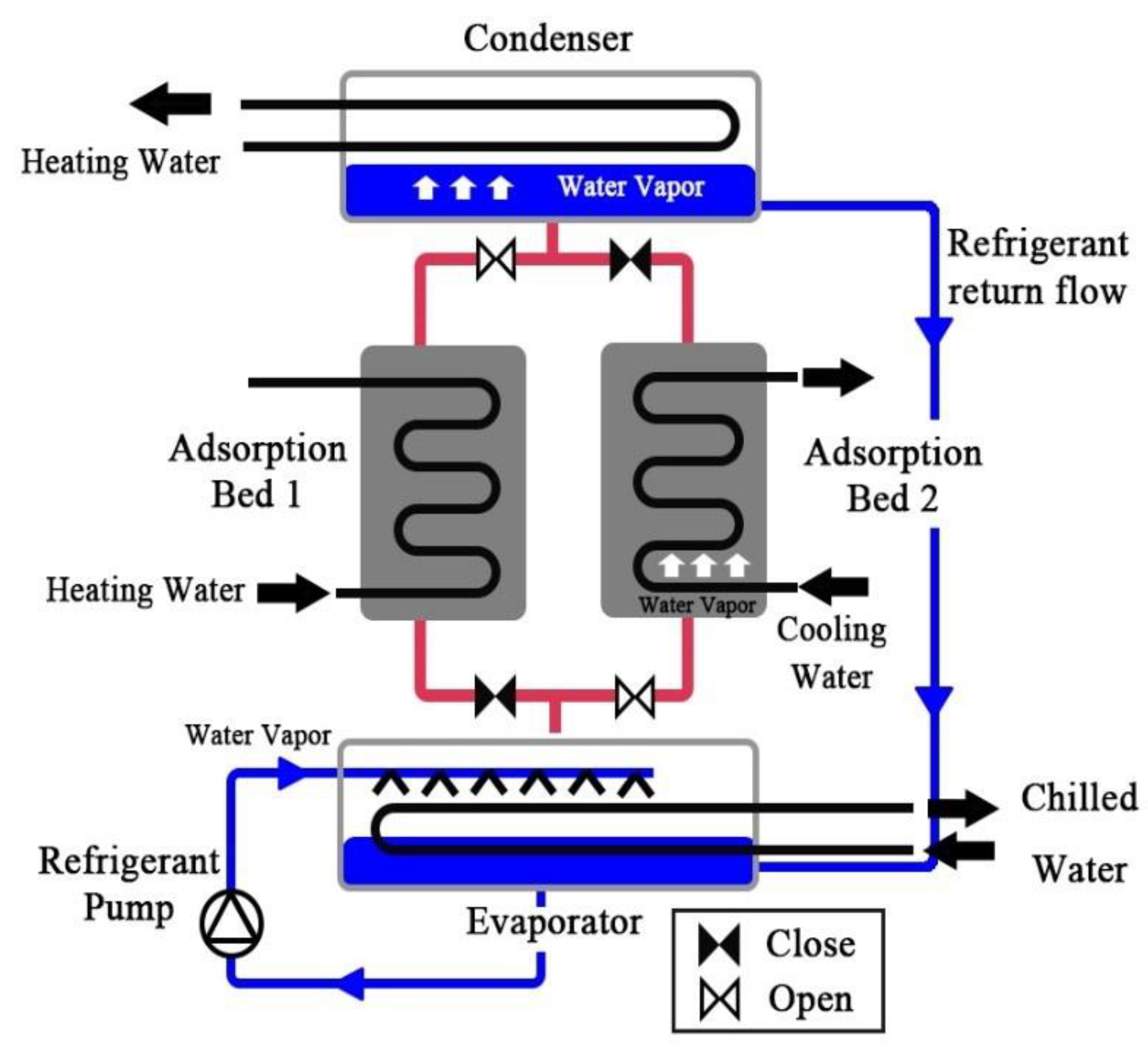
2.2.1. Adsorption Bed

Our recent research showed that inter- and intra-particle mass transfer kinetics have a large influence on system performance, and therefore it is highly recommended that models be chosen considering a valid diffusion ratio range (Hong et al. [16]). Given a sufficiently large value of Deq/rp, the non-isobaric model and linear driving force (LDF) model were used for the inter- and intra-particle mass transfer models, respectively.
Non-isobaric model (Hong et al. [3], Niazmand et al. [4], Hong et al. [13]):
ε t ρ v t + ( ρ v u v ) + ρ a d s q ¯ t = 0
The distribution of the velocity of water vapor ( u v ) in the adsorption bed follows the porous model, expressed as Darcy’s law:
u v = K app μ v P
The apparent permeability, Kapp, was obtained using the following equations. (Bird et al. [17], Lee and Thodos [18], Ruthven [19]):
K app = K d + ε b μ v τ P D eq
K d = ε b 3 d p 2 150 ( 1 ε b ) 2
D eq = ( 1 0.02628 T 3 / M V P σ 2 Ω + 1 48.5 d p o r e T b / M v ) 1
τ = ε b 0.4
d pore = 0.6166 d p
where σ and Ω are σ = 2.641Å and Ω = 2.236.
When substituting Equation (2) into Equation (1), the following equation can be obtained:
ε t ( P R v T ) t + ( ρ v K app μ P ) + ρ ads q ¯ t = 0
LDF model (Hong et al. [16]):
q ¯ t = 15 D so r p 2 exp ( E a R u T b ) ( q * q ¯ )
The pre-exponent constant, Dso, and the activation energy of diffusion, Ea, were 0.000254 m/s2 and 42,000 J/s, respectively. The adsorption amount is expressed in isotherms and the isotherm of SWS-1 L from Saha et al. [20] was used:
q * = 1.6 × 10 12 C q * [ 1 + ( 2 × 10 12 C q * ) 1.1 ] 1 / 1.1
C q * = P exp ( Δ H R v T b )
The heat transfer equation in the adsorption bed is expressed as:
ρ C p T b t + ( ρ v C p , v u v T b ) = ( k b T b ) + ρ a d s Δ H q ¯ t
where ρ C p is the heat capacity of the entire bed, including the adsorbent and the refrigerant.
ρ C p = ε t ( ρ v C p , v ) + ρ a d s ( C p , ads + q ¯ C p , b )
ε t = ε b + ( 1 ε b ) ε p
The second term on the right-hand side in Equation (12), ρ a d s Δ H q ¯ t , is the heat generated by adsorption and desorption.
The energy equation for the heat transfer fluid is as follows:
ρ C p T f t + Z ( ρ f C p , f u f T f ) = Z ( k f T f Z ) + 4 d i h ( T c , R = R i T f )
The last term is a heat exchange term. The convective heat transfer coefficient, h, is obtained from the following correlations:
N u = 0.023 Re 0.8 Pr n n = 0.3 for cooling phase n = 0.4 for heating phase
The energy equation for the copper fin-tube is as follows:
ρ C p , c T c t = ( k c T c )

2.2.2. Evaporator

The evaporator is connected to the adsorption bed during the adsorption process and allows the evaporated refrigerant vapor to move towards the adsorption bed. Therefore, the energy equilibrium equation of the evaporator is expressed as (Miyazaki et al. [21]):
( m C p ) eva d T eva d t = θ h fg ( m a d s d q ads d t ) + ( m ˙ C p ) chill ( T chill , in T chill , out ) C p ( T con T eva ) m a d s d q des d t
Note that the evaporator was modeled by LPM, like in most previous research. The novelty in this work was to model the sorption bed from the refined CFD simulation, and simultaneously include the effect of the evaporator and condenser.
The term on the left-hand side in Equation (18) is the heat capacity, showing the internal energy of the entire evaporator. The first term on the right-hand side shows the cooling energy generated by the latent heat of evaporation. θ is equal to 1 or 0 during adsorption (or desorption) and the switching period, respectively. The second term on the right-hand side is the heat exchange between the evaporator and chilled water, and the last term is the heat needed to lower the temperature of the regenerated refrigerant from Tcon to Teva.

2.2.3. Condenser

The condenser is connected to the adsorption bed during the desorption process to condense the desorbed vapor. The regenerated fluid is sent to the evaporator through the U-tube. The condenser energy equilibrium equation is as follows (Miyazaki et al. [21]):
( m C p ) con d T con d t = θ h fg ( m a d s d q des d t ) + ( m ˙ C p ) con ( T cool , in T cool , out ) C p ( T des T con ) m a d s d q des d t
The term on the left-hand side is heat capacity reflecting the internal energy of the entire condenser. The first term on the right-hand side is the latent heat of evaporation. The second term is the heat exchange between condenser and cooling water, and the last term is the heat needed to lower the refrigerant temperature from Tdes to Tcon.

2.2.4. Outlet temperature

The log mean temperature difference (LMTD) determines the outlet temperature of the evaporator and condenser (Miyazaki et al. [21]):
T chill , out = T eva + ( T chill , in T eva ) exp ( ( U A ) eva ( m ˙ C p ) chill )
T cool , out = T con + ( T cool , in T con ) exp ( ( U A ) con ( m ˙ C p ) cool )
where U is the overall heat transfer coefficient and A is the heat transfer area.

2.2.5. Mass balance equation

The mass balance equations are expressed as follows (Miyazaki et al. [21]):
d m eva d t = m a d s [ d q a d s d t + d q d e s d t ]

2.3. Initial and Boundary Conditions

Initial condition for adsorption process:
[ T initial = T ads = 303.15 K P initial = P ads = 1633 Pa q initial = q ads = 0.13 kg / kg
Initial condition for desorption process:
[ T initial = T d e s = 353.15 K P initial = P d e s = 4144 Pa q initial = q d e s = 0.13 kg / kg
Boundary condition:
R = R i , 0 Z Z o : h ( T c T f ) = k c T c R
R = R m , 0 Z Z o : k c T c R = Δ T 1 / h CR = k b T b R , P R = 0
R = R o , 0 Z Z o : T b R = 0 , [ P R = 0 for the pre - heating and pre - cooling phase P = P eva o r P con for the heating and cooling phase
R m R R o at fin - absorbent boundary : k c T c Z = Δ T 1 / h CR = k b T b Z , P Z = 0
[ T f = T a d s a t   Z = 0 ( cooling phase ) T f = T d e s a t   Z = 0 ( heating phase )
where 1/hCR is the contact resistance between the adsorption bed and the tube (or fin), empirically obtained by Zhu and Wang [22] as follows:
1 h CR = ( 0.00122 T 2 0.1699 T + 8.15 ) × 10 3

2.4. Performance Index

The coefficient of performance (COP) and specific cooling power (SCP) were selected as performance indicators, and were defined as the following:
COP = Q eva Q in
SCP = Q eva m a d s t cycle
where Qeva denotes the input heat energy supplied to the sorption bed during the desorption process, mb is the total mass of the solid sorbent, and tcycle means cycle time. When the evaporator and the condenser were assumed to be ideal, as in most previous studies, the cooling energy, Qeva, was obtained as the amount of adsorbed vapor (Equation (33)). However, when the evaporator and the condenser are included in the modeled analysis, the cooling energy should be obtained by using the temperature difference between the inlet chilled water and the outlet chilled water of the evaporator (Equation (34)).
Q eva = L v t des t ads interface ρ v u v d A d t
Q eva = t des t ads { ( m ˙ C p ) chill ( T chill , in T chill , out ) } d t
Q in = t ads t des { ( m ˙ C p ) c o o l ( T cool , in T cool , out ) } d t
where Lv is the latent heat and is expressed as follows:
L v = L ( T e v a ) C P , ads ( T eva T con )

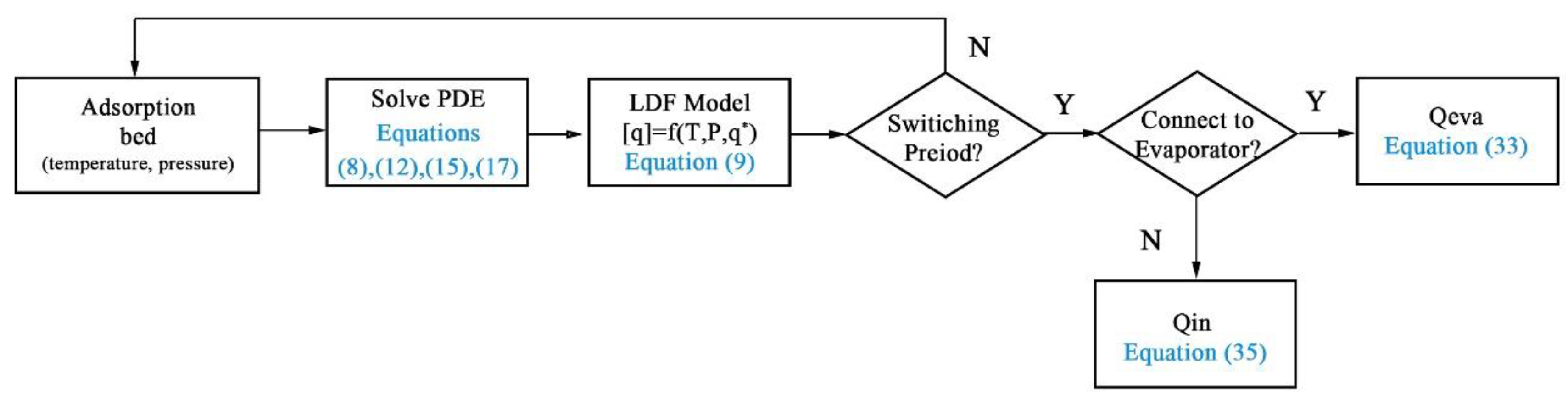
2.5. Numerical Procedure

The detailed numerical procedures used in the two models, i.e., the previous studies which assumed an ideal evaporator and condenser and the newly proposed model, are shown in Figure 3 and Figure 4. The separate analysis of each adsorption bed and its integration with an evaporator and condenser avoids the over-simplified assumptions in the previous model and enables an accurate estimation of bed behavior and evaporator outlet temperature, which results in a more accurate estimation of system performance.

3. Results and Discussion
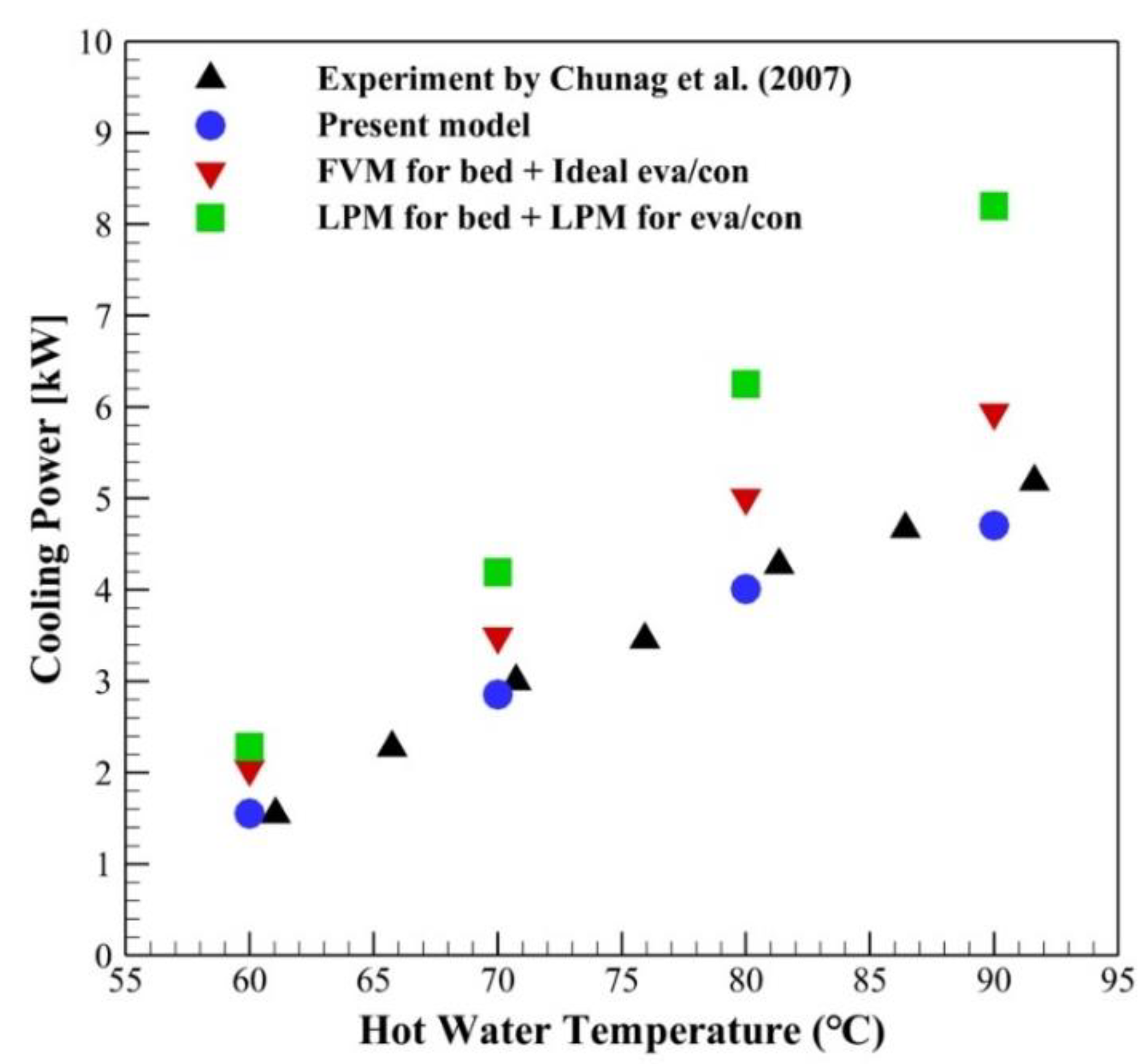
The governing equations subject to the given boundary conditions were solved using STAR-CCM+v12, a commercial computational fluid dynamics (CFD) program, and additional user-supplied codes. The grid dependence was thoroughly tested for 2000~9600 hexagonal grids, and the test results indicated that 4400 grids were sufficient to obtain grid-independent results. The first-order temporal discretization was used to solve the implicit unsteady problem. A hybrid-scheme and a central difference scheme were used for the convection and diffusion terms, respectively. The resulting discretized equations were solved using a Gauss–Seidel algorithm for every time step. Time steps of 0.01 s were used for the isosteric phase and 0.5 s was used for the isobaric phase. The computation time was approximately 24 h for a typical model running on an Intel Core i7-8700 CPU @3.20Ghz, which was two times longer than the earlier model with an ideal evaporator and condenser because two beds were simultaneously analyzed, as described in Figure 4.
All results were obtained after an initial couple of cycles, which ensured that the system had reached a quasi-equilibrium state.
The parameters and operating conditions required for the analysis are summarized in Table 1. The properties of the evaporator and condenser such as overall heat transfer coefficient are given in Miyazaki et al. [21].

3.1. Validation

The cooling capacity of the present model was compared to the results of an experiment by Chang et al. [23]. The numerical analysis was conducted under the operating conditions of Theat = 60–90 ℃, Tcool = 30 ℃, Tchill = 14 ℃, Teva = 15 ℃, tcycle = 12 min, m ˙ cool = 0.6 kg/s, m ˙ heat = 0.48 kg/s. The details of the geometrical shapes of the adsorber, evaporator, and condenser are given in Chang et al. [23].
Figure 5 shows that there is close agreement between the present numerical model and the prior experiment, however, the predictions by LPM or with ideal treatment of the evaporator and condenser are considerably different than the experiment. Most of the earlier studies, about 80%, are based on LPM. The assumption that there is no spatial variation in the adsorption bed, a component which is highly influential on the performance of the adsorption chiller, inherently limits the accuracy of the model. Also, detailed analyses of the effects of geometric features (fin height, fin spacing, tube diameter, and thickness) and the interaction between sorbent material and metallic finned tube, are not feasible in the LPM. The remaining 20% of the studies treat the evaporator and condenser as ideal, even though the adsorption bed was rigorously modeled. In those models, the evaporator and condenser did not interact with the adsorption bed and it is assumed that the evaporator temperature and condenser temperature were fixed, i.e., they assumed an ideal evaporator and condenser. As a consequence, these models inherently overestimated performance, which is the reason most previous numerical results showed higher system performance than the experiment.

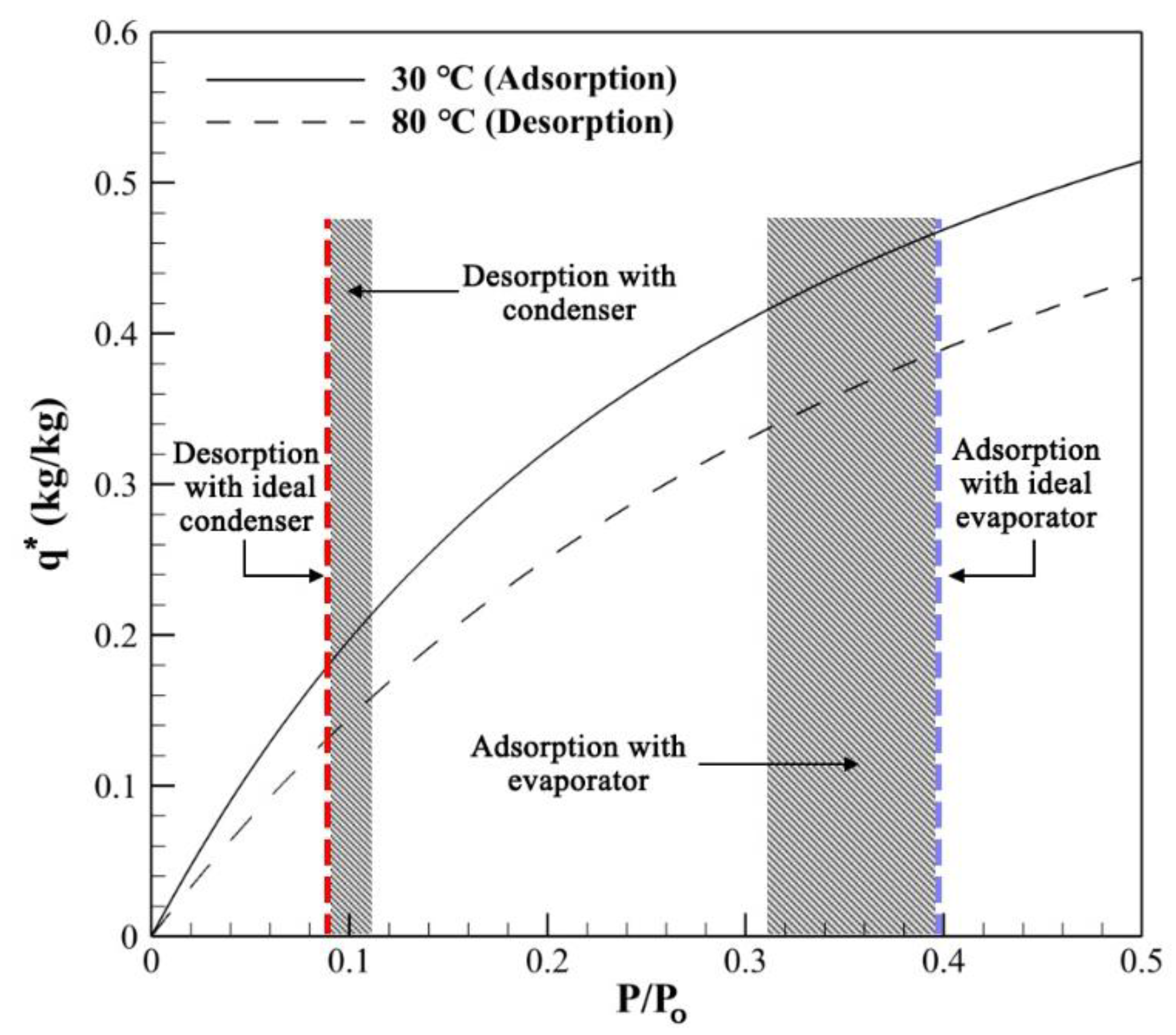
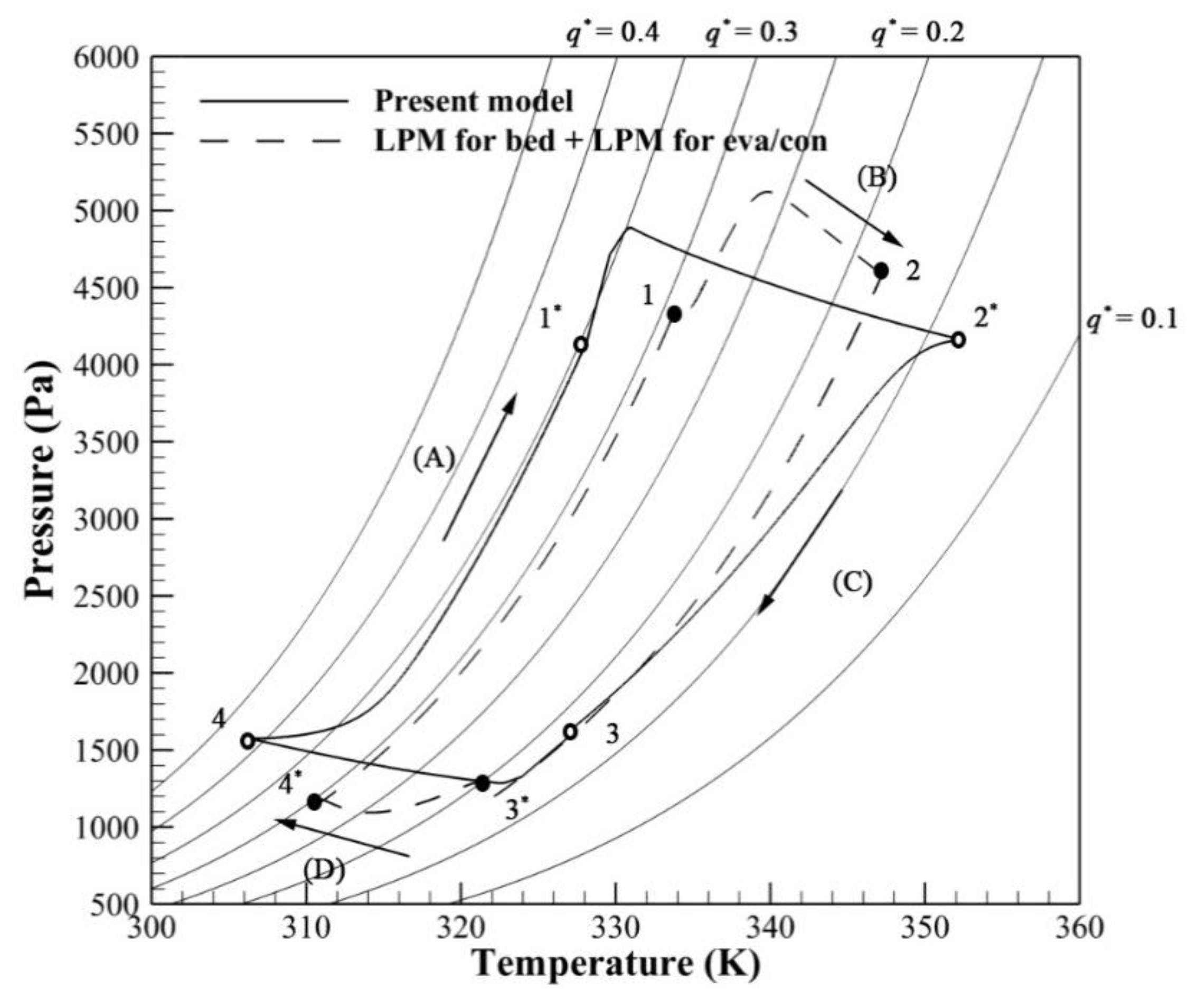
3.2. Effect of Evaporator/Condenser Model

Figure 6 compares the Clapeyron diagram of the present model and the model of an ideal evaporator and condenser, i.e., with a fixed evaporation temperature (15 ℃) and condenser temperature (30 ℃). During the isosteric phase in processes (A) and (C), the valves are disconnected from the evaporator and condenser and the adsorption bed is isolated. Thus, except for the starting (4 and 4’) and end points (1 and 1’), there is no difference between the models.
The processes (B) and (D) are the heating and cooling phases, which are desorbing or adsorbing the vapor. In contrast to the real pressure behavior, which was properly estimated in the present model, the pressure in the idealized model is assumed to be constant at the saturation pressure corresponding to the temperature of the evaporator, 15 ℃, or the condenser, 30 ℃.
Figure 7 shows the isotherm of the adsorbent SWS-1 L and compares the adsorption and desorption amounts corresponding to the ideal and real pressures of the condenser and evaporator. In the model with ideal treatment of the evaporator and condenser, the pressure during the adsorption and desorption process is constant, shown in the bold dashed line in Figure 7, which causes constant q*. On the other hand, in the present model, relative pressure varies from 0.09 to 0.11 during the desorption process and varies from 0.31 to 0.4 during the adsorption process, as described in the hatched region in Figure 7. A larger variation is observed during the adsorption process, which results in 4.2% less adsorption and 1.8% less desorption compared to the ideal evaporator and condenser. This difference is the reason that most previous numerical results overestimated system performance. In the model based on an ideal evaporator and condenser, COP was estimated to be 0.523, which is an overestimate of 16.12%, and SCP was 637 W/kg, which is an overestimate of 24.64%, compared to the present model.

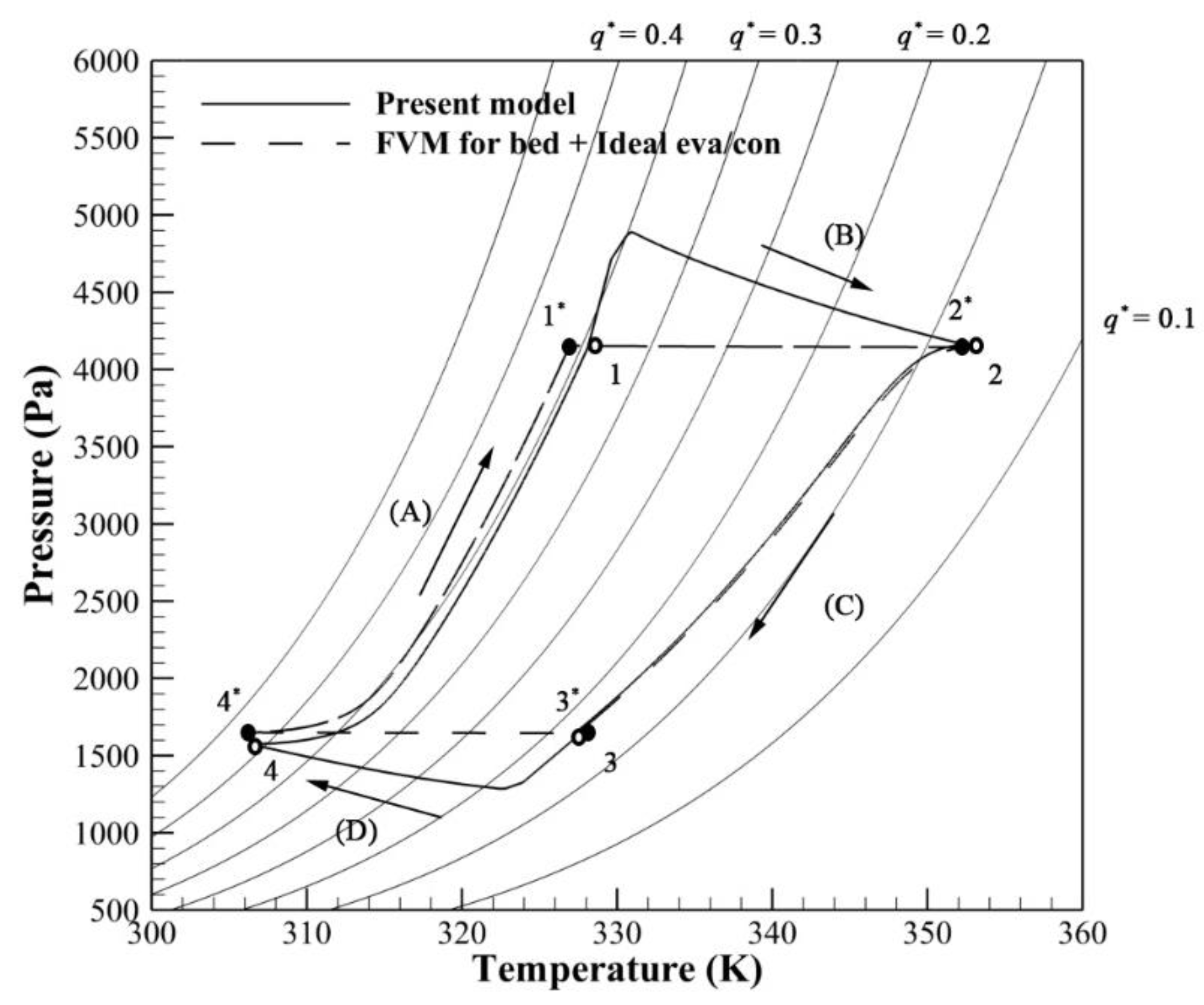
3.3. Effect of Bed Model

For the rough design purpose in system scale analysis, LPM has an advantage because the refined model in beds requires special treatment and much longer computation time (Duong et al. [24]). However, LPM is not enough when higher accuracy or detailed information in beds is required during the process. Figure 8 shows a Clapeyron diagram of the present model and the model based on LPM. The result of LPM was obtained for the same device geometry and operating condition in the present model. The only difference is the treatment of the bed simulation. The processes (A) and (C) are the isosteric phase and the processes (B) and (D) are the heating and cooling phase of the desorbing or adsorbing vapor. Both models allow variable pressure, based on the temperature of evaporation or condensation. However, because the adsorption bed behaviors are different depending on the bed model, processes (B) and (D) in Figure 8 are significantly different. The resulting COP in the model based on LPM for all components was 0.553, which was 22.82% higher than the present model, and SCP was 568 W/kg, which was 11.28% higher than the present model.
In contrast to the LPM, the present model includes the effects of geometric features (fin height, fin spacing, tube diameter, and thickness) and considers the contact resistance between the sorbent material and metallic finned tube, which affirmatively enhances the accuracy of the analysis. There were a lot of studies on geometric optimization in adsorption beds [4,13,25,26,27]. Also, recent coating technology has made it possible to reduce contact resistance and tremendously enhance performance (Rezk [28], Girnik and Aristov [29]). The LPM cannot accommodate all these effects, thus has to limit to estimate the real system performance.
In summary, Figure 9 shows how much the accuracy of COP improved as the model became more precise.

4. Conclusions

In this study, we proposed a novel numerical model for an adsorption chiller including (1) the proper interaction with the evaporator and condenser, and also (2) a rigorous treatment of the adsorption bed. The proposed numerical model was compared with results from experiments and showed close agreement.
Properly accounting for the interaction between the adsorption bed and the evaporator and condenser enhanced the model’s accuracy. Previous models have used a fixed evaporation temperature and condenser temperature, which did not interact with the adsorption bed, which is why the earlier numerical models have normally overestimated system performance.
The model based on an ideal evaporator and condenser resulted in a COP of 0.523, which led to an overestimate of 16.12%, and a SCP of 637 W/kg, which was an overestimate of 24.64%, compared to the present model.
Even when the interaction with the evaporator and condenser was included, excessive simplification of the adsorption bed in previous LPM analyses distorted the actual performance. This is because LPM failed to reflect the geometry effect and contact resistance of the bed, the component which is most influential on adsorption chiller system performance. As a result, the estimated COP was 0.553, and the SCP was 568 W/kg, which were 22.82% and 11.28% higher respectively, than the present model.
Considering the many studies on the geometric optimization of the adsorption bed, and recent coating technology to enhance system performance, producing an accurate estimation of adsorption chiller performance requires not only proper interaction with the evaporator and condenser, but also rigorous modeling of the adsorption bed.

Author Contributions

Conceptualization, writing—review and editing, J.D.C.; validation, X.Q.D. and N.V.C.; formal analysis, investigation and writing—original draft preparation, W.S.L. and M.Y.P. All authors have read and agreed to the published version of the manuscript.

Funding

This research was supported by Basic Science Research Program through the National Research Foundation of Korea (NRF) funded by the Ministry of Education (No. 2017R1D1A1B05030422)

Conflicts of Interest

The authors declare no conflict of interest.

References

  1. Freni, A.; Bonaccorsi, L.; Proverbio, E.; Maggio, G.; Restuccia, G. Zeolite synthesised on copper foam for adsorption chillers: A mathematical model. Micropor. Mesopor. Mater. 2009, 120, 402–409. [Google Scholar] [CrossRef]
  2. Askalany, A.A.; Saha, B.B.; Ahmed, M.S.; Ismail, I.M. Adsorption cooling system employing granular activated carbon-R134a pair for renewable energy applications. Int. J. Refrig. 2013, 36, 1037–1044. [Google Scholar] [CrossRef]
  3. Hong, S.W.; Ahn, S.H.; Chung, J.D.; Bae, K.J.; Cha, D.A.; Kwon, O.K. Characteristics of FAM-Z01 compared to silica gels in the performance of an adsorption bed. Appl. Therm. Eng. 2016, 104, 24–33. [Google Scholar] [CrossRef]
  4. Niazmand, H.; Talebian, H.; Mahdavikhah, M. Bed geometrical specifications effects on the performance of silica/water adsorption chillers. Int. J. Refrig. 2012, 35, 2261–2274. [Google Scholar] [CrossRef]
  5. Mahdavikhah, M.; Niazmand, H. Effects of plate finned heat exchanger parameters on the adsorption chiller performance. Appl. Therm. Eng. 2013, 50, 939–949. [Google Scholar] [CrossRef]
  6. Hong, S.W.; Kwon, O.K.; Chung, J.D. Application of an embossed plate heat exchanger to adsorption chiller. Int. J. Refrig. 2016, 65, 142–153. [Google Scholar] [CrossRef]
  7. Khan, M.Z.I.; Alam, K.C.A.; Saha, B.B.; Hamamoto, Y.; Akisawa, A.; Kashiwagi, T. Parametric study of a two-stage adsorption chiller using re-heat—The effect of overall thermal conductance and adsorbent mass on system performance. Int. J. Therm. Sci. 2006, 45, 511–519. [Google Scholar] [CrossRef]
  8. Uyun, A.S.; Akisawa, A.; Miyazaki, T.; Ueda, Y.; Kashiwagi, T. Numerical analysis of an advanced three-bed mass recovery adsorption refrigeration cycle. Appl. Therm. Eng. 2009, 29, 2876–2884. [Google Scholar] [CrossRef]
  9. Miyazaki, T.; Akisawa, A.; Saha, B.B. The performance analysis of a novel dual evaporator type three-bed adsorption chiller. Int. J. Refrig. 2010, 33, 276–285. [Google Scholar] [CrossRef]
  10. Duong, X.Q.; Cao, N.V.; Hong, S.W.; Ahn, S.H.; Chung, J.D. Numerical study on the combined heat and mass recovery adsorption cooling cycle. Energy Technol. 2018, 6, 296–305. [Google Scholar] [CrossRef]
  11. Ng, K.C.; Thu, K.; Saha, B.B.; Chakraborty, A. Study on a waste heat-driven adsorption cooling cum desalination cycle. Int. J. Refrig. 2012, 35, 685–693. [Google Scholar] [CrossRef]
  12. Zajaczkowski, B. Optimizing performance of a three-bed adsorption chiller using new cycle time allocation and mass recovery. Appl. Therm. Eng. 2016, 100, 744–752. [Google Scholar] [CrossRef]
  13. Hong, S.W.; Ahn, S.H.; Kwon, O.K.; Chung, J.D. Optimization of a fin-tube type adsorption chiller by design of experiment. Int. J. Refrig. 2015, 49, 49–56. [Google Scholar] [CrossRef]
  14. Li, S.; Wu, Y. Theoretical research of a silica gel–water adsorption chiller in a micro combined cooling, heating and power (CCHP) system. Appl. Energy 2009, 86, 958–967. [Google Scholar] [CrossRef]
  15. Schicktanz, M.; Nunez, T. Modelling of an adsorption chiller for dynamic system simulation. Int. J. Refrig. 2009, 32, 588–595. [Google Scholar] [CrossRef]
  16. Hong, S.W.; Ahn, S.H.; Kwon, O.K.; Chung, J.D. Validity of intra-particle models of mass transfer kinetics in the analysis of a fin-tube type adsorption bed. J. Mech. Sci. Technol. 2014, 28, 1985–1993. [Google Scholar] [CrossRef]
  17. Bird, R.B.; Stewart, W.E.; Lightfoot, E.N. Transport Phenomena; Wiley: Hoboken, NJ, USA, 1960. [Google Scholar]
  18. Lee, H.; Thodos, G. Generalized treatment of self-diffusivity for the gaseous and liquid states of fluids. Ind. Eng. Chem. Fundam. 1983, 22, 17–26. [Google Scholar] [CrossRef]
  19. Ruthven, D.M. Principles of Adsorption and Adsorption Process; Wiley: Hoboken, NJ, USA, 1984. [Google Scholar]
  20. Saha, B.B.; Chakraborty, A.; Koyama, S.; Aristov, Y.I. A new generation cooling device employing CaCl2-in-silica gel–water system. Int. J. Heat. Mass. Transf. 2009, 52, 516–524. [Google Scholar] [CrossRef]
  21. Miyazaki, T.; Akisawa, A.; Saha, B.B.; El-Sharkawy, I.I.; Chakraborty, A. A new cycle time allocation for enhancing the performance of two-bed adsorption chillers. Int. J. Refrig. 2009, 32, 846–853. [Google Scholar] [CrossRef]
  22. Zhu, D.; Wang, S. Experimental investigation of contact resistance in adsorber of solar adsorption refrigeration. Sol. Energy 2002, 73, 177–185. [Google Scholar] [CrossRef]
  23. Chang, W.S.; Wang, C.C.; Shieh, C.C. Experimental study of a solid adsorption cooling system using flat-tube heat exchangers as adsorption bed. Appl. Therm. Eng. 2007, 27, 2195–2199. [Google Scholar] [CrossRef]
  24. Duong, X.Q.; Cao, N.V.; Lee, W.S.; Chung, J.D. Module integration in an adsorption cooling system. Appl. Therm. Eng. 2019, 155, 508–514. [Google Scholar] [CrossRef]
  25. Rogala, Z. Adsorption chiller using flat-tube adsorbers—Performance assessment and optimization. Appl. Therm. Eng. 2017, 121, 431–442. [Google Scholar] [CrossRef]
  26. Mitra, S.; Muttakin, M.; Thu, K.; Saha, B.B. Study on the influence of adsorbent particle size and heat exchanger aspect ratio on dynamic adsorption characteristics. Appl. Therm. Eng. 2018, 133, 764–773. [Google Scholar] [CrossRef]
  27. Kowsari, M.M.; Niazmand, H.; Tokarev, M.M. Bed configuration effects on the finned flat-tube adsorption heat exchanger performance: Numerical modeling and experimental validation. Appl. Energy 2018, 213, 540–554. [Google Scholar] [CrossRef]
  28. Rezk, A.; Al-Dadah, R.K.; Mahmoud, S.; Elsayed, A. Effects of contact resistance and metal additives in finned-tube adsorbent beds on the performance of silica gel/water adsorption chiller. Appl. Therm. Eng. 2013, 53, 278–284. [Google Scholar] [CrossRef]
  29. Girnik, I.S.; Aristov, Y.I. Making adsorptive chillers more fast and efficient: The effect of bi-dispersed adsorbent bed. Appl. Therm. Eng. 2016, 106, 254–256. [Google Scholar] [CrossRef]
Figure 1. The schematic of the 2-bed adsorption chiller with two adsorption beds, evaporator, and condenser.
Energies 13 01901 g001
Figure 2. Current numerical model of adsorption bed with a circular fin-tube heat exchanger.
Energies 13 01901 g002
Figure 3. Flowchart of performance evaluation strategy based on the numerical method with an ideal evaporator and condenser.
Energies 13 01901 g003
Figure 4. Flowchart of performance evaluation strategy based on the present model including realistic evaporator and condenser.
Energies 13 01901 g004
Figure 5. A comparison of cooling capacity per 24.5 kg of sorbent mass from three numerical models, and experimental results (Chang et al. [23]).
Energies 13 01901 g005
Figure 6. Clapeyron diagram of the present model and the model based on ideal treatment of the evaporator and condenser.
Energies 13 01901 g006
Figure 7. Comparison of adsorption and desorption interval for the two models in Figure 6.
Energies 13 01901 g007
Figure 8. Clapeyron diagram of the present model and the model based on the lumped parameter method (LPM) for all components of the bed, evaporator, and condenser.
Energies 13 01901 g008
Figure 9. Accuracy improvement in coefficient of performance (COP) and specific cooling power (SCP).
Energies 13 01901 g009
Table 1. Parameter values and operating conditions of the adsorption chiller.
ParameterValues
Fin pitch1.68 mm
Fin thickness0.06 mm
Fin height6.82 mm
Inner diameter of tube9.6 mm
Outer diameter of tube8.8 mm
Fluid velocity1 m/s
Heating temperature80 ℃
Cooling temperature30 ℃
Cycle time900 s
Density700 kg/m3
Specific heat900 J/kgK
Thermal conductivity0.2 W/mK
Heat of adsorption2760 kJ/kg
Total porosity0.6352

