Article

Effect of Bypass Control and Room Control Modes on Fan Energy Savings in a Heat Recovery Ventilation System

1
Korea Institute of Civil Engineering & Building Technology, 283 Goyangdae-Ro, Ilsanseo-Gu, Goyang-Si, Gyeonggi-Do 10223, Korea
2
Department of Architectural Engineering, Yonsei University, 50 Yonsei-ro, Seodaemun-gu, Seoul 03722, Korea
*
Author to whom correspondence should be addressed.
Energies 2020, 13(7), 1815; https://doi.org/10.3390/en13071815
Submission received: 11 March 2020 / Revised: 5 April 2020 / Accepted: 7 April 2020 / Published: 9 April 2020
(This article belongs to the Special Issue Low and Zero Energy Highly Performing Buildings)

Abstract

:
This study makes a novel attempt to analyse the effect of the bypass control and room control modes on ventilation energy saving in an 84 m2 housing unit, which is the most frequently constructed unit-type among newly constructed apartment buildings in Korea. A heat recovery ventilation system was installed. The fan power consumption was measured via field experiments and analyses were made for potential energy savings. Experiments to confirm the power-saving effect owing to the application of the room control mode were performed under the heat recovery and bypass modes, using three air flow rates (0.5, 1.0 and 1.5 ACH). Additionally, the annual energy saving based on the application of the mixed mode (both bypass and room control modes) was calculated. The results obtained showed that when the mixed mode was employed, ventilation energy saving up to 10.76%–16.56%, which is greater than that obtained using only the heat recovery mode, was realized. Additionally, compared with all-room-ventilation, 26.69%–61.84% of ventilation energy could be saved if the mixed mode was applied only to the living room.

1. Introduction

Building permit requests for the construction of residential apartment buildings accounted for approximately 72% of the total number of building permits that were applied for within the first half of 2019 in Korea [1]. According to the policy report of the Ministry of Land, Infrastructure and Transport in Korea, it is required that new apartments buildings that can accommodate 30 or more households, that are to be constructed as from 2025, should be designed as zero energy buildings with over 20% energy self-sufficiency [2].
Previously constructed buildings have low insulation levels, which result in a high rate of heat loss via the skin of the building, high heating and cooling energy consumption [3]. However, recent buildings were constructed in compliance with new regulations regarding the thermal performance of the building skin. For this reason, the thermal performance of the buildings reach the level of a passive house of which airtightness is very high [4]. Additionally, owing to the introduction of heat recovery ventilation systems (HRVS) which minimise heat loss resulting from the inflow of outdoor air, energy loss from heating and cooling has further reduced [5], even though these HRVS require an additional power supply for the operation of the fan.
Given that residential buildings are considered to be in use 24 h a day, the energy consumed by the fan throughout the day by the ventilation system may be higher than expected. Furthermore, owing to its characteristics, when electrical energy is converted to other forms via primary energy consumption, the proportion of the total primary energy consumed is relatively higher than in the case of a heating facility that uses a gas heating source [6]. Given that the deterioration of air quality owing to ultra-fine dust particles is now a major social issue [7], high-performance filters are installed in the ventilation unit to remove ultra-fine dust particles. This results in a further increase in the amount of energy used to power the fan [8].
One possible strategy that can be employed to reduce fan power consumption using HRVS is the application of a bypass control mode, which allows outdoor air to flow directly into the supply duct inlet without passing through the heat exchanger element and air filter. The volume of air removed by the HRVS decreases as the pressure loss in the system increases. Therefore, the choice of the fan is based on the internal and external static pressure and usually, the internal static pressure is greatly influenced by the heat exchanger element as well as the air filter inside the HRVS [9].
Due to the distinct seasonal characteristics of Korea, significant power saving can be achieved by implementing a heat recovery mode and a bypass control mode. Thus, the use of HRVS with a separate air flow path for the bypass mode is legally recommended in Korea [10]. Since early 2010, newly constructed apartment buildings in Korea have been equipped with HRVS, which reduce heating and cooling energy losses via ventilation. However, residents are often unaware of the existence of the bypass control mode [11]. Moreover, to reduce HRVS production cost, manufacturers often minimise the size of the air flow path for the bypass control mode. Thus, in reality, the application of the bypass mode of most HRVS is challenging and substantial power saving is not achieved [12].
Another strategy for the reduction of fan power consumption is the application of a room control mode. For apartment buildings with mechanical ventilation systems, the ventilation system is usually operated for the entire apartment unit regardless of actual use. Given that not all the rooms are in use at all times, significant amounts of energy are lost, owing to fan power consumption. Therefore, operating the ventilation system such that it operates only in rooms that are in use by residents can result in a considerable decrease in fan power consumption. Additionally, if a mode with low static pressure drop, such as bypass control mode, is applied in appropriate cases, it will significantly contribute to fan power energy saving.

2. Literature Review

The implementation of HRVS for the purpose of heating and cooling energy reduction, which started in Sweden in the 1970s [13], has since become an active research focus. Particularly, HRVS for residential buildings have recently emerged as an important research focus [14] that emphasises energy conservation in the building sector [15]. In this light, several studies on heating and cooling energy saving in residential buildings via the use of HRVSs have been conducted [16,17]. The extent of energy saving resulting from the use of HRVSs varies depending on the composition of the HRVS as well as the field conditions [18,19,20]. For example, the heat recovery performance of an HRVS may depend on the airtightness and insulation of a building [19]. It may also depend on variables, such as local climate, outdoor temperature and ventilation air flow rate [20,21]. However, given that it is impossible to arbitrarily control the external environment, analysing heat recovery performance using real field experiments is time consuming and requires great effort. Therefore, many studies on HRVS performance evaluation have been conducted in test chambers or via simulations.
In Korea, a considerable number of studies on the performance HRVS in relation to outdoor air conditions have been conducted given that the climate in Korea is different from that of Europe, where HRVS were originally developed. Experiments conducted in a chamber to evaluate the heat recovery performance of HRVS based on various outdoor air conditions have been reported [22,23]. Additionally, several simulation studies on the evaluation of the heat recovery performance of HRVS have also been reported [24,25,26]. Even though a few field studies have been reported [27], such field studies are restricted by the limitations associated with the field condition.
Currently, several on-going studies [28,29,30,31,32,33,34,35] are focused on fan energy saving via the control of fans use in HRVS as follows:
  • Energy saving using a hybrid system that combines HRVS with natural ventilation [28],
  • CO2-based demand control ventilation systems (DCVS) [29],
  • Occupancy-based DCVS [30],
  • Temperature-based DCVS [31], and
  • Systems that combine two or more of the above [32,33,34,35].
According to the above-mentioned methods, separately applying CO2-based DCVS, occupancy-based DCVS or temperature-based DCVS only can result in fan energy saving in HRVS up to 15%–26% [28,29,30,31] and combining two or more of these abovementioned control techniques can result in energy saving up to 60%.
Thus, a variety of studies on ventilation energy saving in residential buildings in diverse fields have been reported. However, the drawback associated with these studies is that the analyses were based on computer simulations [28,29,30,31,32,33,34,35]. Very few field experiments have been conducted to analyse the fan energy savings of HRVS applied in Korean apartment building [27] and based on existing literature, no field experiments have been conducted to investigate fan energy saving via the combination of a bypass control mode and a room control mode in the HRVS that are installed in Korean apartment buildings.
The use of performance tests on HRVS in chambers to verify their actual field performance is associated with several drawbacks. The HRVS installed in apartment buildings consist of several components, including an outdoor air supply inlet and an exhaust outlet, a ventilation unit, a supply duct and an exhaust duct, which all have an effect on internal and external static pressure. Thus, a comprehensive analysis from the perspective of the entire ventilation system is needed.
Thus, the aim of this novel study was to analyse ventilation energy saving in apartment buildings in Korea using data derived from on-site experiments performed to investigate the use of the bypass and room control modes in HRVS.

3. Materials and Methods

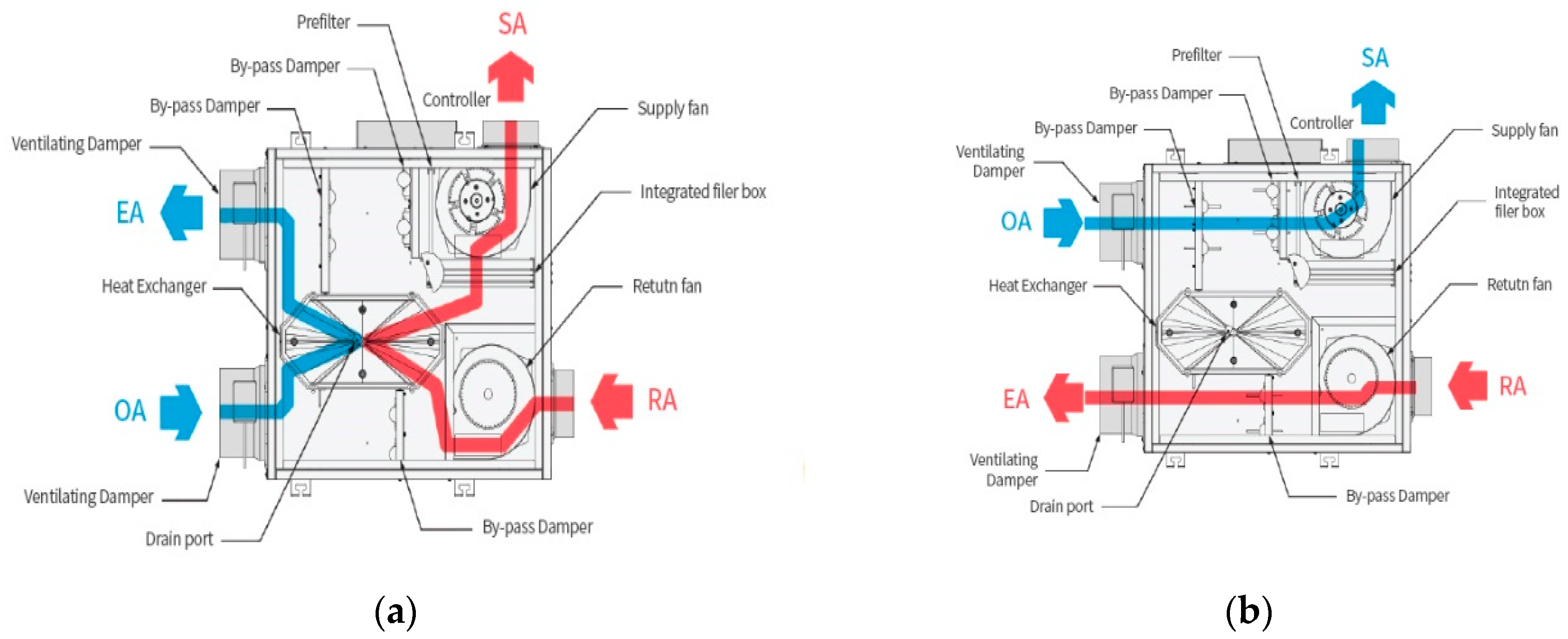
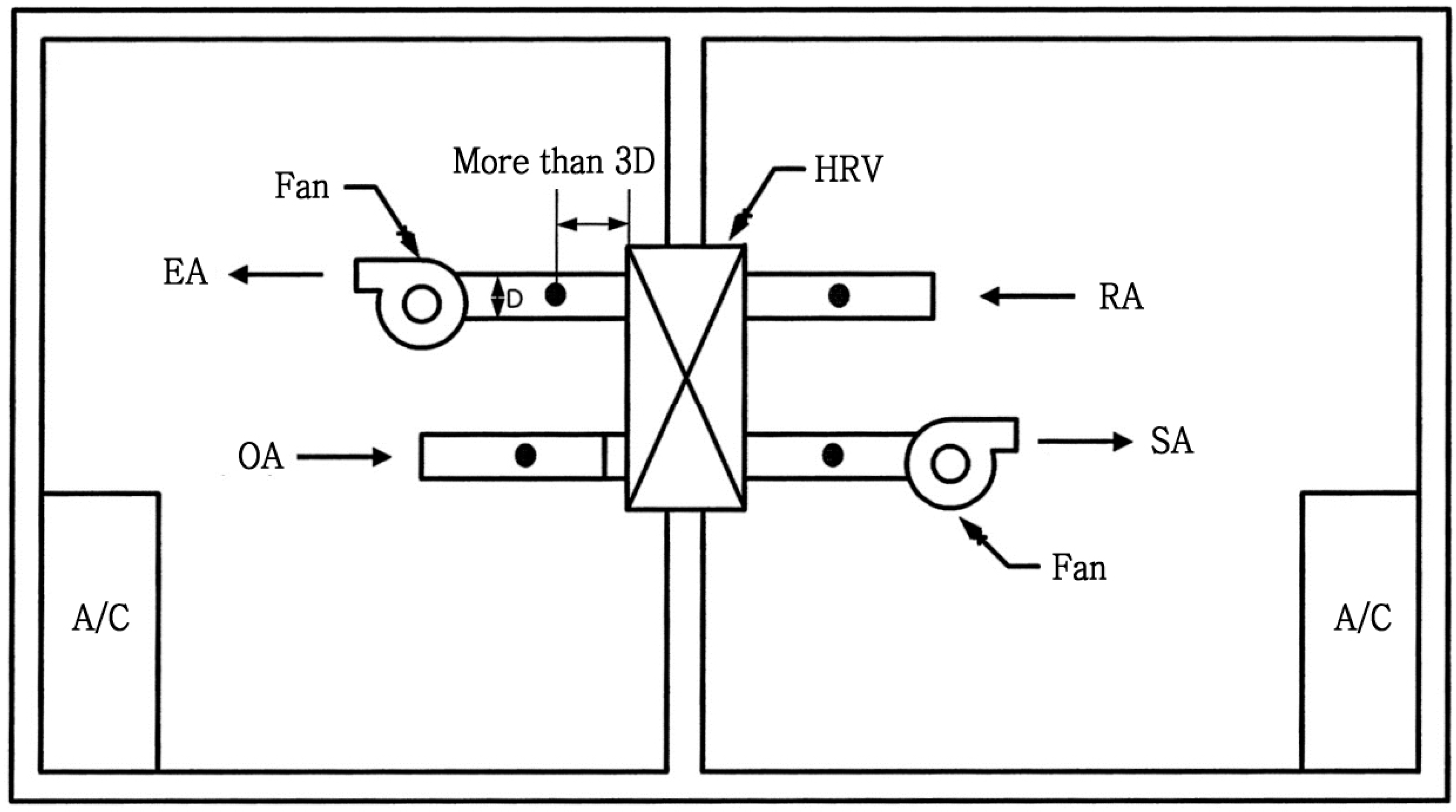
3.1. Bypass and Room Control Modes

The bypass control mode is a control strategy that directly introduces outdoor air into the supply fan unit, without allowing the air to pass through a heat exchanger so as to reduce the frictional resistance introduced by the different components of the ventilation system (Figure 1b). This is useful during season changes when outdoor air must be introduced into indoor spaces without heat exchange, unlike the heat recovery mode (Figure 1a).
The room control mode is a control strategy that allows the occupants to ventilate only the rooms of their choice by operating air diffusers. Figure 2 shows a conceptual diagram of a system that uses a wall pad to make the room control mode possible. Regarding apartment buildings in Korea with installed HRVS, most often, the only control mode option that is available is the “On/Off” control for all rooms. Thus, this results in unnecessary consumption of energy given that the ventilation system operates all the time even in unoccupied rooms.
In this study, the fan energy saving potential of the HRVS installed in typical Korean apartments in combination with the use of a bypass control mode and a room control mode, was analyzed in the following order.
  • The typical apartment unit where the experiments would be carried out was selected and the HVRS was installed.
  • Specific equipment and programs were installed for measuring and monitoring fan power consumption and air flow rates. They are described in detail in the next section.
  • Testing, Adjusting and Balancing (TAB) was performed to achieve proper operation of HVRS. In this study, the TAB is carried out for air flow balancing of each room.
  • Different cases according to the application of the bypass control mode and the room control mode were designed in order to analyse the annual fan energy saving potential.
  • Fan power consumption was measured depending on the different cases under the on-site experimental conditions.
  • The annual fan energy saving potential of the HRVS installed in typical Korean apartments was calculated with the application of measured fan power consumption and the standard weather data for Seoul

3.2. Experimental Methods for Fan Power Monitoring

3.2.1. Research Process for Fan Power Monitoring

A detailed description of the research process is provided below.
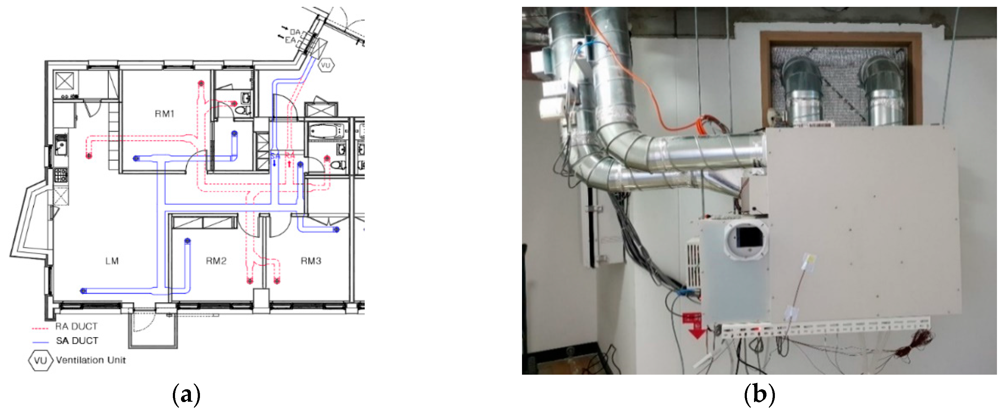
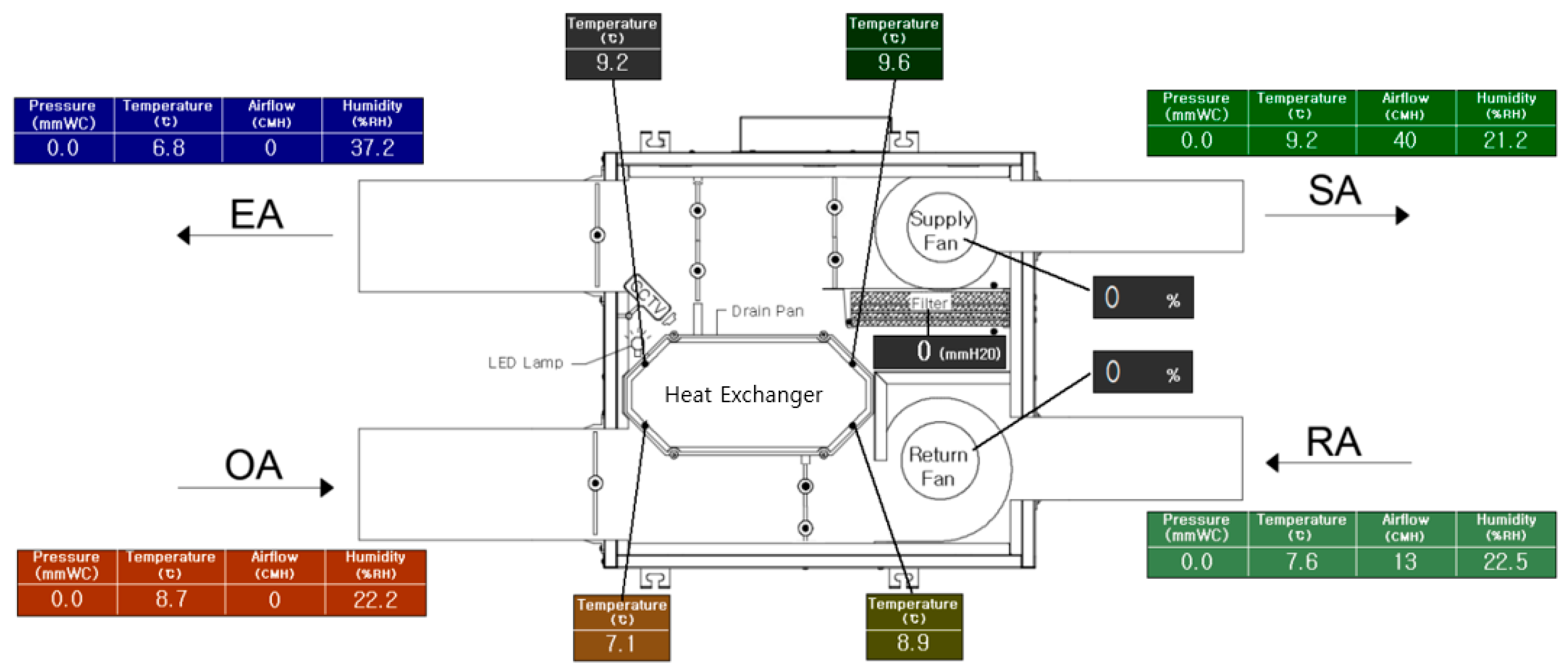
  • An 84 m2 housing unit, which is the most popular housing unit type constructed in Korea, was selected for this study. This unit consists of a single living room and three bedrooms, with the living room and two rooms on the south side and one room on the north side (Figure 3). SA, RA, EA and OA in Figure 3 indicate Supply Air, Return Air, Exhaust Air and Outdoor Air, respectively.
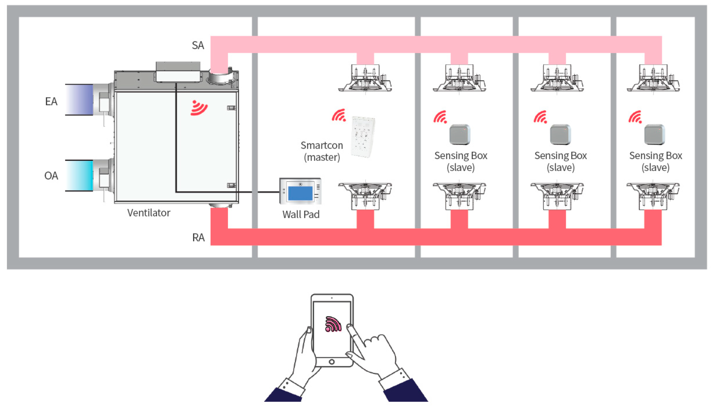
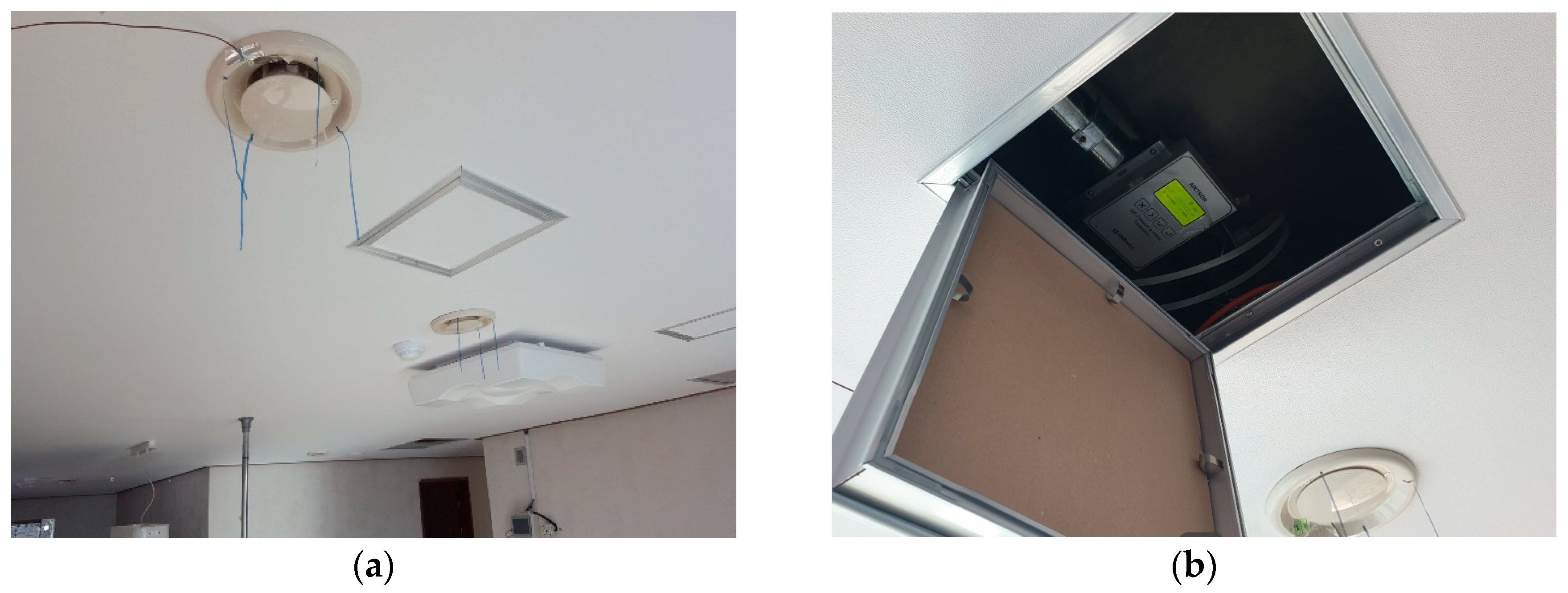
  • The pilot model of the experiment was established and the sensor, the power line communication (PLC) and the measurement program were installed (Figure 4).
The airflow rate and static pressure in the duct were calculated using the values measured by the self-averaging multi-pitot tube. The temperature and humidity measurement sensors were composed of capacitive polymer cells and their detailed specifications and tolerances are described in Table 1.
In this study, a variable air volume (VAV) diffuser system was employed and it was used to control the ventilation volume. When an external controller delivers an operation command to the diffuser controller through the RS 485 communication line, the controller rotates the stepping motor built into the diffuser cone (Figure 5). The stepping motor then rotates the lead screw that is connected to the motor shaft and this feed screw, which is connected to the fixing nut in the centre of the support moves the diffuser cone vertically. Here, the guide rod fixed to the diffuser cone prevents rotational movement; thus, the diffuser cone moves up and down to adjust the opening rate.
The driving part of the diffuser is driven by a pulse signal that makes precise control possible. Thus, only the necessary amount of air is accurately supplied according to the preference of the occupants of each space, thereby enhancing comfort. With the opening rate at 0% (the fully closed function), airflow into unused rooms can be blocked.
The performance of the HRVS was determined using a chamber test (Figure 6) prior to the experiments (Table 2) based on the KS B 6879: 2017 ‘Heat-recovery ventilators’ method [36]. Given the poor outdoor air quality in Korea owing to the presence of ultra-fine particles [37], three types of filters (pre + carbon + HEPA (H13)) were included in the HRVS and the performance test of this filter combination was conducted according to the KS B 6141: 2002 “Air filter units for ventilation” test method [38], the pressure drop resulting from the use of the filters was determined to be 45 Pa (300 CMH).
3.
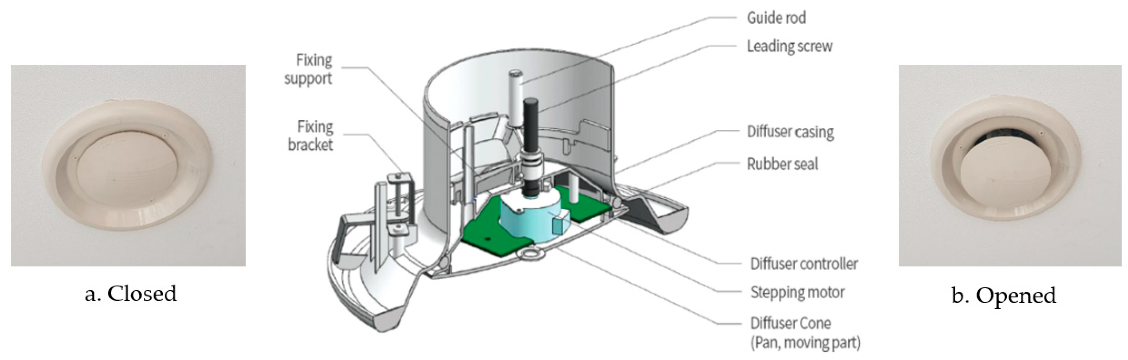
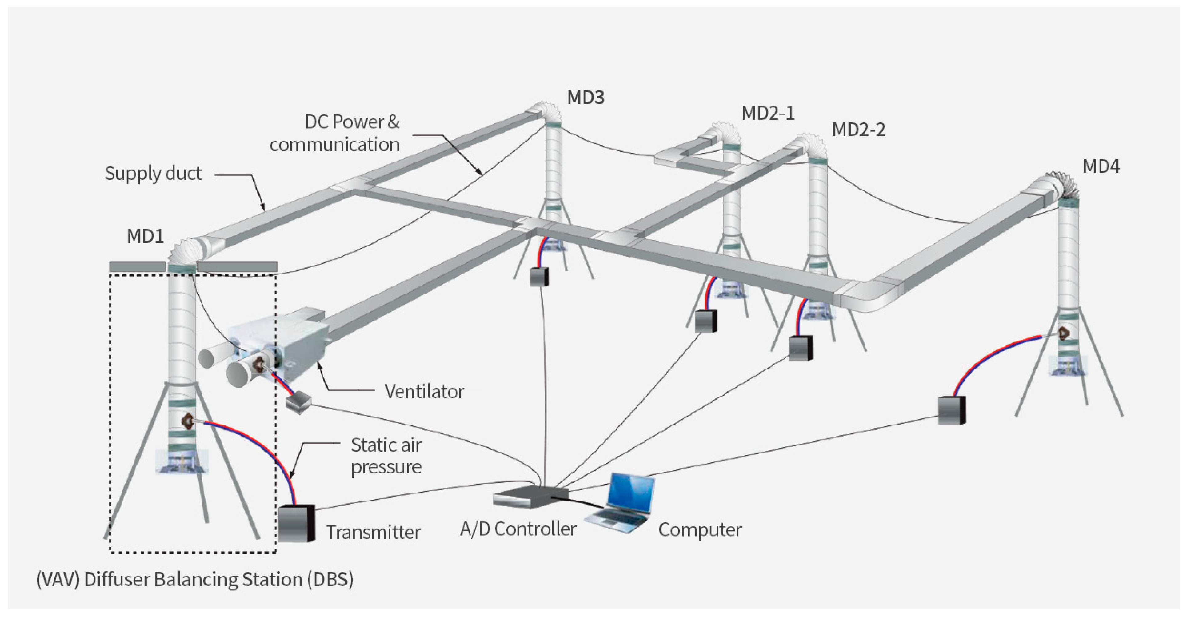
To control the ventilation in the different spaces of the building unit as well as data collection, the experimental equipment was installed in the 84 m2 housing unit and the various data were collected using a measurement program as shown in Figure 7. The air flow rate in each of the diffusers in the rooms was measured using an air flow measurement transmitter (Figure 8, Airtron, Taeheung M&C, Korea) that can measure up to 1 CMH unit per diffuser and an Automatic Air-flow Balancing (AABS) program (Figure 9).
4.
By assuming possible room use patterns, the annual fan energy consumption was derived. The data obtained from the different experiments were then compared with data on the whole unit ventilation system.

3.2.2. Experimental Conditions

According to the ASHRAE Standard 62.2 (2019) [39], a housing unit destined for human habitation must provide a total ventilation rate that satisfies the values in Table 3.
In Korea, it is required that for an apartment unit, the mechanical ventilation system should provide a 0.5 air change per hour (ACH) [40]. Additionally, it is required that the ventilation system must have at least three steps of airflow control function (i.e., minimum, optimum and maximum or more). Thus, to satisfy the minimum ventilation requirement in this 84 m2 housing unit consisting of 3 bedrooms and a living room, an air flow rate of 28 L/s is required. Thus, 100.8 m3 of fresh air is required per hour, which is similar to the 96.6 m3/h (2.3 m ceiling height applied) provided at 0.5 ACH in the Korean standard, which is similar to the minimum requirement of the ASHREAE Standard 62.2. In this regard, test cases were decided taking into consideration the following three combinations:
  • Three steps of air flow rate, including 0.5, 1.0 and 1.5 ACH, were configured.
  • Four kinds of Room Control cases were considered.
Given that in Korea, the living room is considered as a family gathering place and serves as a pathway, it was assumed to be under a minimum airflow rate 24 h per day and the three other cases were included based on the number of rooms in use, that is,
1)
Living Room only is ventilated
2)
Living Room + Room 1 are ventilated
3)
Living Room + Room 1 + Room 2 are ventilated
4)
Living Room + Room 1 + Room 2 + Room 3 are ventilated
3.
Bypass Control and Heat Recovery Modes were employed.
The heat recovery mode is used during seasons when residents need heating or cooling for the rooms, while the bypass control mode is used during seasons when heating and cooling are unnecessary. In this study, the fan power consumption associated with the heat recovery mode as well as the bypass mode was examined depending on the cases mentioned above.
Before commencing the experiments, the diffuser opening was adjusted by performing TAB so that the supply air flow into all rooms satisfied the target air change per hour for each room (Table 4). Due to limitations associated with the field experiment, ±0.1 ACH was considered acceptable for the target value. In order to confirm the results, room’s ACH and the power consumption were checked three times and averaged.
The fan power consumptions were then measured with the diffusers of the target rooms opened, while the others were closed based on the different cases that were tested. A total of 24 case combinations derived as shown in Table 5 were tested in this study.
The experimental results for the 24 cases mentioned above are summarised in Appendix A.

3.3. Analytical Methods for Annual Fan Energy

The annual fan energy consumption was calculated by combining the fan power consumption data obtained from the 24 case combinations shown in Table 5 as follows:
1. The outdoor air temperature range was set. In the case of small buildings such as residential apartments, a control system that uses a temperature sensor is more realistic than one that uses enthalpy [41]. Thus, it was assumed that only an outdoor temperature sensor was needed for the bypass control mode.
Based on existing literature, 26 °C is considered as the dry bulb temperature upper limit (i.e., the indoor set temperature) while 18 °C is considered as the lower limit (the minimum temperature that does not generate cold draft) [42]. In another study, 17 °C was considered as the lower limit, taking into consideration the heat gain via the duct [42]. However, in this study, such heat gain was not considered.
2. The temperatures of Seoul’s warmest month are greater than 10 °C and that of the coldest month are usually lower than −3 °C, which correspond to the Dwa climatic type according to Köppen-Geiger scheme [43]. Using the standard weather data of Seoul as shown in Figure 10 [44], periods of the year during which outdoor temperature falls between 18 and 26 °C and below 18 °C, were calculated as shown in Table 6. This data represents standard weather data recorded over the past 10 years (2005–2014) based on actual measurement data from 70 domestic weather stations in accordance with ISO 15927-4 [42].
Based on Table 6, periods (hours) that require the use of the bypass control mode are present in all months except between December and February. Particularly, the table shows that the application of the bypass control mode could be necessary for even up to 400–500 h in July and August, which are the mid-summer months.

4. Results and Analysis

4.1. Fan Power Reductions Resulting from the Bypass and Room Control modes

Primarily, the fan power saving potential based on the application of a room control mode in the HRVS was analysed for three airflow rates and the results are shown in Figure 11. According to Table 7, when the LR only was ventilated under the experimental conditions, 43%–61% of the power required for all-room-ventilation was consumed, that is, when all the residents were present in the LR and the diffusers in the other rooms were closed, a power saving of ~39%–57% could be realised. Additionally, when R3 only was excluded from the ventilation, it was possible to ventilate the LR, R1 and R2 with 82%–89% of the power required for all-room-ventilation, meaning that with the room control mode, a power saving of ~11%–57% compared with all-room-ventilation, could be attained under the experimental conditions.
The fan power saving potential following the application of the bypass control mode in combination with the four room control modes was analysed for the three airflow rates and the results obtained are shown in Figure 12.
As shown in Table 8, when the LR only was ventilated under the experimental condition, 61%–66% of the power required for all-room-ventilation was consumed and when R3 only was excluded from the ventilation, it was possible to ventilate LR, R1 and R2 with 86%–92% of the power required for all-room-ventilation, meaning that with the room control mode, power saving up to ~8%–39% compared with all-room-ventilation, could be attained under the experimental condition.
To evaluate the fan power saving potential of the bypass control mode, its resulting fan power consumption was compared with that resulting from the heat recovery mode.
The bypass control and heat recovery modes showed different electrical energy consumptions owing to the difference in their internal resistance. In the bypass control mode, outdoor air flows directly into the supply fan without passing through the heat exchanger element or filter, resulting in a decrease in internal resistance by approximately 12–15 mmAq under the given experimental conditions.
Figure 13 shows the different fan power consumptions resulting from the 24 experimental case combinations. Under the experimental conditions, the higher ACH cases tended to result in graphs with a steeper gradient, meaning that in the higher ACH cases, a higher fan power may be required for the same air flow rate increase than the expected value. For example, the slope of 1.5 HR is steeper than that of 1.0 HR, whilst the slope 1.0 HR’s slope is steeper than that of 0.5 HR.
As shown in Table 9, by applying the bypass control mode instead of the heat recovery mode, a 0.5, 1.0 and 1.5 ACH using only 57%–62%, 45%–58% and 45%–64%, respectively, of the fan power required for the heat recovery mode was possible under the experimental conditions.

4.2. Fan Energy Savings Resulting from the Bypass and Room Control Modes

To analyse the yearly fan power saving, the annual fan power consumption for ventilation was calculated by combining the measured fan power consumptions from the 24 case combinations employed in this study.
The annual fan energy consumption for ventilation purposes was analysed when the heat recovery mode and bypass control mode were appropriately combined based on the outdoor temperature and the four room control modes were applied.
Regarding the heating and cooling time, the application of the minimum requirement of 0.5 ACH for energy saving is common; however, the higher air flow rate can be used based on individual preferences. Additionally, for the rapid introduction of a pleasant indoor air, in most cases, the use of the bypass mode is expected more than the use of 0.5 ACH.
As shown in Table 10, when the heat recovery mode and the bypass control mode were used with the same airflow rates alternately (mixed mode), a fan energy saving of 10.76%–16.56% relative to the use of only the heat recovery mode was obtained. Additionally, the application of 0.5 ACH_HR + 1.0 ACH_BP for a year could result in a fan energy saving of 3.35%–9.44% compared to the application of 0.5 ACH_HR, even though the total airflow rate in this case was higher than that of 0.5 ACH_HR
Particularly, when the room control mode was applied in the mixed mode, fan energy savings of 29.69% (Case1_①/②) to 61.84% (Case3_③/④) compared with the all-room-ventilation system could be realised using only currently-applied heat recovery system. Analysis showed an increase in fan energy savings with higher air flow rates, meaning that the energy saving techniques mentioned above are significantly more essential in seasons when residents need more air changes such as spring and autumn.

5. Discussion

This study was conducted to identify the energy saving potential associated with the use of the bypass and room control modes in HRVS and to avoid overstating the potential of the study, the analysis was conducted based on a conservative hypothesis.
1. In reality, the temperature of the incoming outdoor air may first rise due to the heat generated by the fan. Thereafter, the heated air moves through the duct and rises a second time due to a higher room temperature. Thus, the actual temperature of the outdoor air that can be introduced to ensure ventilation should be less than 18 °C as suggested in this study. This makes more energy saving possible.
2. In this study, the effect of the bypass control mode was limited to fan power saving owing to a pressure drop. If the indoor air temperature was higher than the outdoor air temperature in early or late summer, the possibility of additional energy savings, such as cooling energy saving owing to a colder outdoor air, can be considered by increasing the air flow rate in the bypass control mode.
3. The cooling design temperature suggested by the energy-saving design standard of the building is 26–28°C. In this study, the upper limit temperature of the outdoor air introduced into the building unit was considered to be 26 °C, which is a conservative value based on the reference. However, if it was set at 28 °C, more fan energy could be saved and based on the calculations, it was found that when the upper limit temperature was considered to be 28 °C, an additional 1.87%–2.89% of fan energy could be saved.
Presently, most of the HRVS installed in apartment buildings in Korea do not consist of a bypass flow path that can provide optimum air flow and the room control mode is applied only in a few cases. The findings of this study indicate that a simple algorithm that can switch the HRVS between the bypass control mode and the heat recovery mode based on temperature sensors, using occupants’ ventilation on-off system for each room as they do for the lights, would significantly reduce ventilation-associated energy consumption per year.

6. Conclusions

In this study, an actual HRVS was installed in the 84 m2 type housing unit, which is the most common housing unit type among newly constructed buildings in Korea and the fan power consumption was measured using field experiments and potential fan energy savings were analysed. The experiments to confirm the power-saving effect using the room control mode were performed taking into account the heat recovery and bypass modes as well as different airflow rates, that is, 0.5, 1.0 and 1.5 ACH.
The experimental results can be summarised as follows.
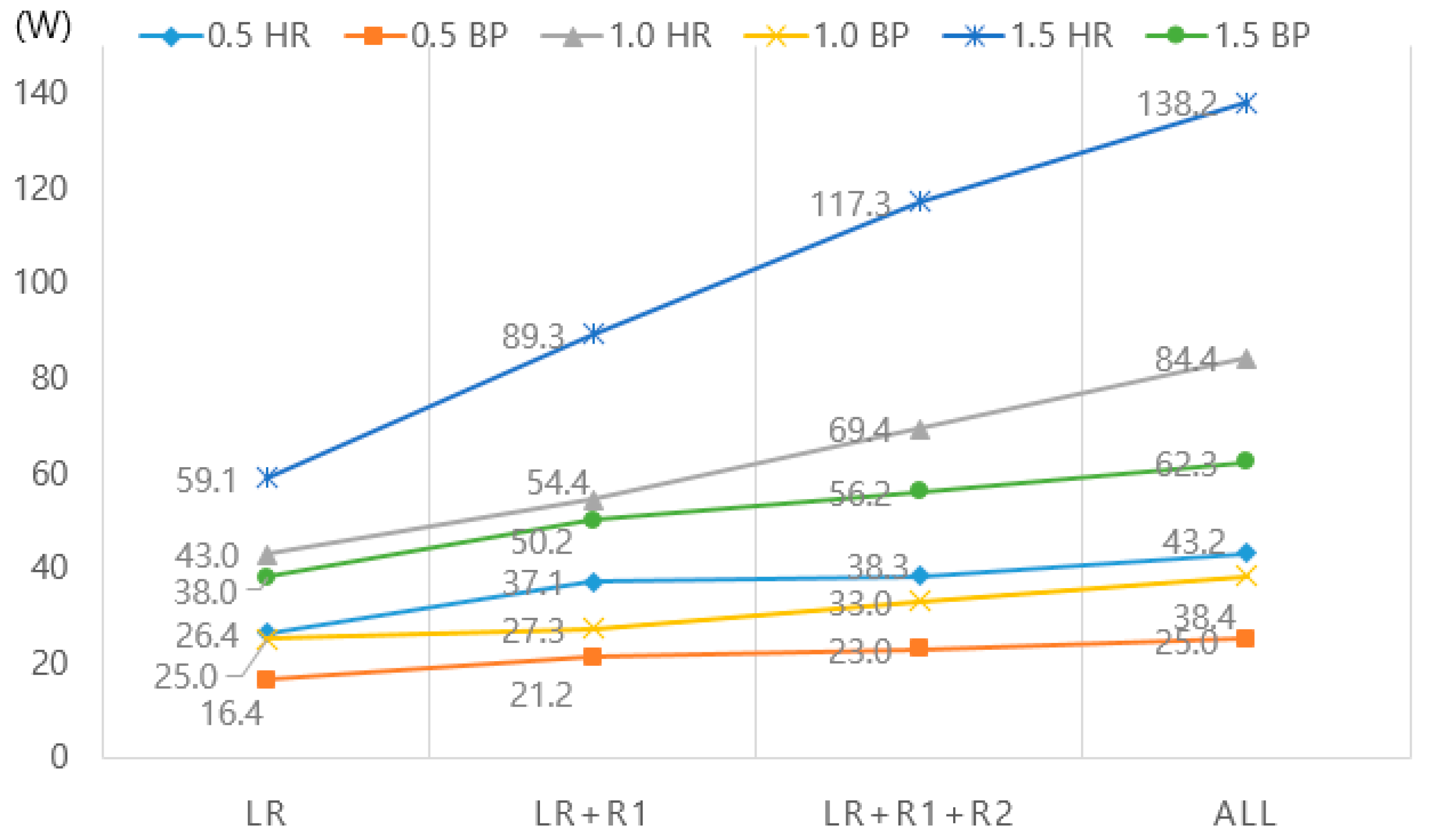
  • When the heat recovery mode was employed in association with the room control mode, there was a decrease in fan power consumption by 11% for the LR + R1 + R2 case and up to 57% for the LR case, compared with all-room-ventilation.
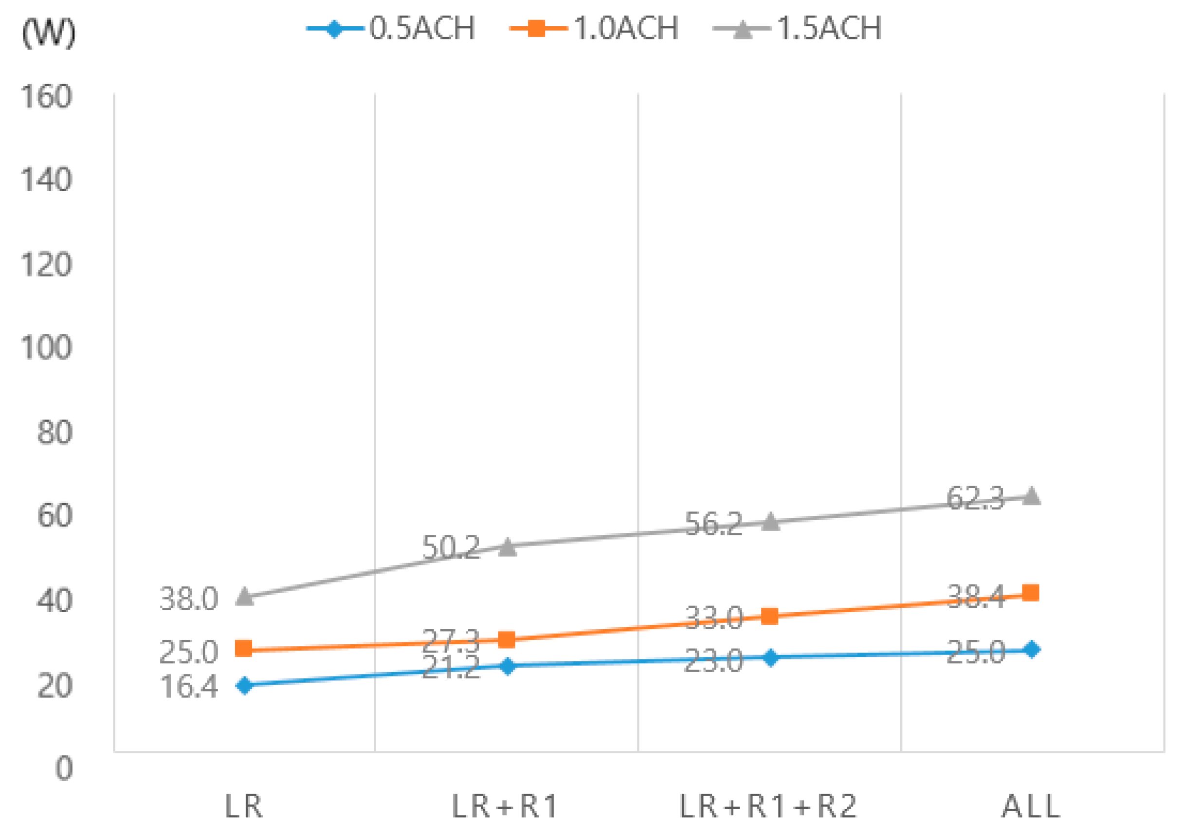
  • When the bypass control mode was employed in conjunction with the room control mode, there was a decrease in fan power consumption by 8% for the LR + R1 + R2 case and up to 39% for the LR case, compared with all-room-ventilation. Additionally, 36% to 55% of fan power could be saved with the application of the bypass control mode compared with the heat recovery mode.
  • The annual power energy savings were calculated based on the experimental results and the mixed mode, which included Cases 1, 2 and 3 showed a power energy saving that was 10.76%–16.56% higher than that observed with the heat recovery mode only. Furthermore, the calculations showed that ventilation energy can be saved by up to 26.69%–61.84% when the mixed mode was applied only to the living room, compared with the all-room-ventilation that is usually applied in the apartment buildings in Korea.
  • The results of the experiments conducted in this study demonstrated that the bypass and room control modes of HRVS can result in an annual fan energy saving up to ~10.76%–61.84%. Additionally, even if the air flow rate of the bypass control mode was twice that of the heat recovery mode (mixed mode Case 4), an annual fan energy of the bypass control mode was lower than the fan energy used in the heat recovery mode only HR mode Case 4).
This study had the following limitations.
First, a simple on/off system was used as the control method, that is, an automatic control algorithm was not applied to control the HRVS and this might have contributed to the slight differences between the results obtained in this study and those observed in reality because of the many variables involved such as the malfunctioning of sensors. Thus, the application of an automatic control algorithm will be considered in future experiments aimed at investigating annual energy saving potential.
Second, bypass control mode can be operated in two cases; with passing filters and without passing filters. In this study, only the case without passing filters was analyzed because the goal of this research was to present potential fan energy savings via the use of the bypass control mode and the room control mode. Research on energy consumption depending on the different filters will be carried out in the next study.
Nevertheless, the results thus obtained can contribute to guide future energy-related regulations on building ventilation. Additionally, in future, they can also contribute to the realization of the zero energy housing policy established by the Korean government.

Author Contributions

K.C. performed the experiments, analyzed the data and wrote the original draft; D.C. carried out project administration; D.C. and T.K. reviewed and edited the paper. All authors have read and agreed to the published version of the manuscript.

Funding

This study is part of a research project conducted with funding from the Ministry of Science and ICT. [Project Code: 20200037-001].

Conflicts of Interest

The authors declare no conflict of interest.

Appendix A

Table A1. Summary of the results of the experiment.
CASEModeLRR1R2R3Power
(W)
ACHCMHACHCMHACHCMHACHCMH
1HR_0.5_1HR0.532 26.4
2HR_0.5_2HR0.6360.515 37.1
3HR_0.5_3HR0.6360.5180.412 38.3
4HR_0.5_4HR0.5280.5170.4140.61843.2
5HR_1.0_1HR1.063 43.0
6HR_1.0_2HR1.1660.933 54.4
7HR_1.0_3HR1.1661.0341.133 69.4
8HR_1.0_4HR1.1681.0371.1341.13284.4
9HR_1.5_1HR1.590 59.1
10HR_1.5_2HR1.61011.450 89.3
11HR_1.5_3HR1.61001.4501.546 117.3
12HR_1.5_4HR1.6961.4511.4441.543138.2
13BP_0.5_1BP0.533 16.4
14BP_0.5_2BP0.6360.413 21.2
15BP_0.5_3BP0.6370.4150.519 23.0
16BP_0.5_4BP0.6400.5160.6170.61925.0
17BP_1.0_1BP0.957 25.0
18BP_1.0_2BP0.9560.931 27.3
19BP_1.0_3BP0.9570.9330.931 33.0
20BP_1.0_4BP1.0641.1381.1331.12938.4
21BP_1.5_1BP1.487 38.0
22BP_1.5_2BP1.6961.554 50.2
23BP_1.5_3BP1.5931.5541.549 56.2
24BP_1.5_4BP1.5931.5521.5481.54062.3

References

  1. Ministry of Land, Infrastructure and Transport(MLIT). 2019 Statistics about New Building Permission. Available online: https://www.eais.go.kr (accessed on 10 January 2020).
  2. MLIT. The Second Plan for Green Buildings (20~24); Policy Report; MLIT: Seoul, Korea, 2020.
  3. Kim, D.; Jung, G.; Kim, Y.; Kim, S. A Comparative Study on Heating Energy Consumption for Apartment Based on the Annually Strengthened Criteria of Insulation. Energy Eng. 2013, 22, 83–89. [Google Scholar] [CrossRef] [Green Version]
  4. Lee, H.; Maeng, S.; Kim, I.; Ahn, J. A study on the relationship between the existing building load for the advance ZEB certification system. Energy Eng. 2018, 27, 21–27. [Google Scholar]
  5. Jung, J.; Chae, Y. Performance Evaluation of Plate-Type Enthalpy Exchanger for Residential buildings. In Proceedings of the Society of Air-Conditioning and Refrigerating Engineers of Korea Conference, Ganwon, Korea, 19 June 2016; pp. 621–624. [Google Scholar]
  6. Dodoo, A.; Gustavsson, L.; Sathre, R. Primary energy implications of ventilation heat recovery in residential buildings. Energy Build. 2011, 43, 1566–1572. [Google Scholar] [CrossRef]
  7. Son, G. Ventilation Systems for removing fine dust, The Society of Air-Conditioning and Refrigerating Engineers of Korea. Mag. Sarek 2018, 47, 16–23. [Google Scholar]
  8. Bae, S.; Jung, M. A ventilation system with air cleaning function for apartment buildings, Korean Institute of Architectural Sustainable Environment and Building Systems(KIAEBS). Mag. KIAEBS 2017, 11, 23–30. [Google Scholar]
  9. Kim, J.; Lee, J.; Hwang, D.; Byun, U. The Analysis of AHU Fan Power Reduction Effects for Heat Exchanger By-pass system. In Proceedings of the SAREK Winter Conference, Seoul, Korea, 22 November 2014; pp. 275–278. [Google Scholar]
  10. Ministry of Land, Infrastructure and Transport. Notification No. 2015-1108, Energy saving Design Standards of Buildings; MLIT: Tokyo, Japan, 2016.
  11. Ju, J.; Park, J.; Jeon, Y.; Kim, D. A Study on the Usage Status and Satisfaction of the Ventilation System installed in Apartment Houses. J. Archit. Inst. Korea 2015, 31, 185–192. [Google Scholar]
  12. Bypass Ventilation Mode for Only Air Supply Causes Controversy. Available online: http://www.kharn.kr/news/article.html?no=11763 (accessed on 20 January 2020).
  13. Fehrm, M.; Reiners, W.; Ungemach, M. Exhaust air heat recovery in buildings. Int. J. Refrig. 2002, 25, 439–449. [Google Scholar] [CrossRef]
  14. Buyle, M.; Braet, J.; Audenaert, A. Life cycel assessment in the construction sector: A review. Renew. Sustain. Energy Rev. 2013, 26, 379–388. [Google Scholar] [CrossRef]
  15. O’Connor, D.; Calautit, J.K.S.; Hughes, B.R. A review of heat recovery technology for passive ventilation applications. Renew. Sustain. Energy Rev. 2016, 54, 1481–1493. [Google Scholar] [CrossRef]
  16. Ian Ridley, I.; Clarke, A.; Bere, J.; Altamirano, H.; Lewis, S.; Durdev, M.; Farr, A. The monitored performance of the first new London dwelling certified to the Passive House standard. Energy Build. 2013, 63, 67–78. [Google Scholar] [CrossRef] [Green Version]
  17. Cuce, P.M.; Cuce, E.; Riffat, S. A novel roof type heat recovery panel for low-carbon buildings: An experimental investigation. Energy Build. 2016, 113, 133–138. [Google Scholar] [CrossRef]
  18. Mardiana, I.A.; Riffat, S.B. An experimental study on the performance of enthalpy recovery system for building applications. Energy Build. 2011, 43, 2533–2538. [Google Scholar] [CrossRef]
  19. Tommerup, H.; Svendsen, S. Energy savings in Danish residential building stock. Energy Build. 2006, 38, 618–626. [Google Scholar] [CrossRef]
  20. Roulet, C.A.; Heidt, F.D.; Foradini, F.; Pibiri, M.C. Real heat recovery with air handling units. Energy Build. 2001, 33, 495–502. [Google Scholar] [CrossRef]
  21. Zeng, C.; Liu, S.; Shukla, A. A review on the air-toair heat and mass exchanger technologies for building applications. Renew. Sustain. Energy Rev. 2017, 75, 753–774. [Google Scholar] [CrossRef]
  22. Han, H.; Choo, Y. A Study on Heat Transfer Characteristics and Uncertainty of Heat Recovery Ventilator for Various Outdoor Temperature/Humidity Conditions. Korean J. Air Cond. Refrig. Eng. (KJACR) 2008, 20, 608–613. [Google Scholar]
  23. Choi, S.; Lee, J.; Park, M.; Kim, S.; Kim, G. A Performance Prediction on the Element Cores of Total Heat Recovery Ventilator According to Outdoor Conditions. J. Archit. Inst. Korea 2009, 25, 241–248. [Google Scholar]
  24. Jung, M.; Oh, B. An Experimental Study on Performance Improvement for Exhaust Heat Recovery Ventilation System in a Lightweight Wall. Korean J. Air Cond. Refrig. Eng. 2014, 26, 61–66. [Google Scholar]
  25. Kim, G.; Lee, J. A Study on Operating Method by Energy Evaluation and Performance Evaluation of Heat Recovery Ventilator According to Outdoor Conditions. Korean J. Air Cond. Refrig. Eng. 2008, 20, 57–64. [Google Scholar]
  26. Kim, S.; Lee, J.; Lee, Y. Performance Evaluation of an Energy Recovery Ventilator with Various Outdoor Climate Conditions. J. Archit. Inst. Korea 2008, 24, 261–268. [Google Scholar]
  27. Choi, Y.; Song, D. An Evaluation on Energy Recovery Performance of the Ventilation System in Multi-Residential Building by Field Measurement. Korean J. Air Cond. Refrig. Eng. 2017, 29, 68–73. [Google Scholar]
  28. Turner, W.J.N.; Walker, I.S. Using a ventilation controller to optimse residential passive ventilation for energy and indoor air quality. Build. Environ. 2013, 70, 20–30. [Google Scholar] [CrossRef]
  29. Seong, N.C. Energy requirements of a multi-sensor based demand control ventilation system in residential buildings. In Proceedings of the 31st Air Infiltration and Ventilation Center Conference, Seoul, Korea, 26–28 October 2010. [Google Scholar]
  30. Mortensen, D.K.; Walker, I.S.; Sherman, M.H. Optimization of occupancy based demand controlled ventilation in residences. Int. J. Vent. 2011, 10, 49–60. [Google Scholar] [CrossRef] [Green Version]
  31. Less, B.; Walker, I.; Tang, Y. Development of an Outdoor Temperature-Based Control Algorithm For Residential Mechanical Ventilation Control; Ernest Orlando Lawrence Berkeley National Laboratory: Berkeley, CA, USA, 2014. [Google Scholar]
  32. Römer, J.C.; Van Ginkel, J.T. Demand controlled ventilation in a low-energy house: Preliminary results on energy conservation and health effects. In Proceedings of the 4th International Conference on Cold Climate - Heating, Ventilating and Air-conditioning, Trondheim, Norway, 15–18 June 2003. [Google Scholar]
  33. Pavlovas, V. Demand controlled ventilation: A case study for existing Swedish multifamily buildings. Energy Build. 2004, 36, 1029–1034. [Google Scholar] [CrossRef]
  34. Jreijiry, D.; Husaunndee, A.; Inard, C. Numerical study of a hybrid ventilation system for single family houses. Sol. Energy 2007, 81, 227–239. [Google Scholar] [CrossRef]
  35. Laverge, J.; Bossche, N.V.D.; Heijmans, N.; Janssens, A. Energy saving potential and repercussions on indoor air quality of demand controlled residential ventilation strategies. Build. Environ. 2011, 46, 1497–1503. [Google Scholar] [CrossRef] [Green Version]
  36. Korean Standard. KS B 6879; Heat Recovery Ventilator; Korean Standard: Seoul, Korea, 2017. [Google Scholar]
  37. Korean Standard. KS B 6141; Air Filter Units for Ventilation; Korean Standard: Seoul, Korea, 2002. [Google Scholar]
  38. American Society of Heating, Refrigerating and Air-Conditioning Engineers (ASHRAE). Standard 62.2; Ventilation and Acceptable Indoor Air Quality in Residential Buildings; ASHRAE Inc.: Atlanta, GA, USA, 2019. [Google Scholar]
  39. Ministry of Land, Infrastructure and Transport. Presidential Decree No. 467, Regulations on Building Equipment Standards; MLIT: Seoul, Korea, 2017.
  40. Honeywell. Engineering Manual of Automatic Control for Commercial Buildings; Honeywell: Charlotte, NC, USA, 1997. [Google Scholar]
  41. Sung, N.; Hong, S.; Choi, S.; Yoon, D.; Oh, S. Evaluation of Applicability of Outdoor Air Cooling using the Heat recovery Ventilation System in the High-rise Residential Building. In Proceedings of the Korean Institute of Architectural Sustainable Environment and Building Systems Conference, Busan, Korea, 20 October 2012; pp. 79–82. [Google Scholar]
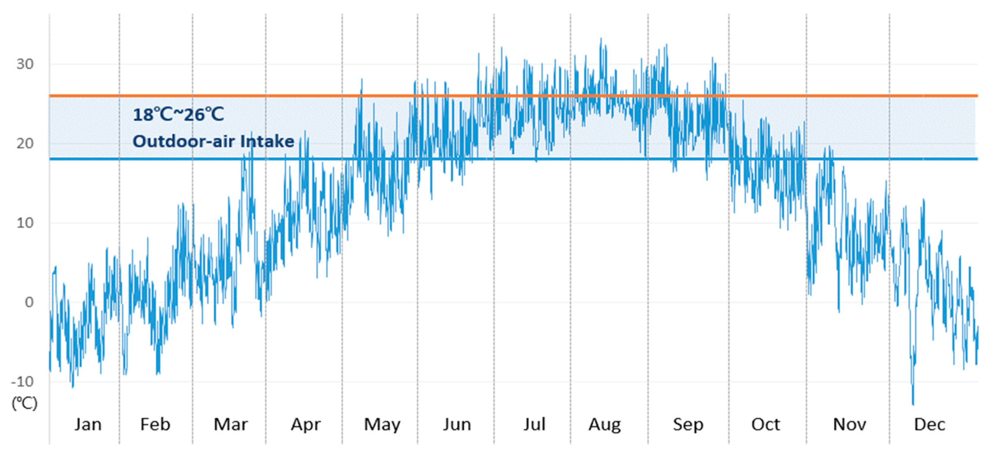
  42. International Organization for Standardization (ISO). Standard 15927-4; Hygrothermal Performance of Buildings-Calculation and Presentation of Climatic Data-Part4: Hourly Data for Assessing the Annual Energy Use for Heating and Cooling; International Organization for Standardization (ISO): Geneva, Switzerland, 2005. [Google Scholar]
  43. Britannica. Available online: https://www.britannica.com/science/Koppen-climate-classification (accessed on 28 March 2020).
  44. Passive House Institute Korea. Weather Data of Korea; Passive House Institute Korea: Seoul, Korea, 2018. [Google Scholar]
Figure 1. Air flow by (a) heat recovery mode and (b) bypass control mode.
Energies 13 01815 g001
Figure 2. Diagram explaining the concept of a room control mode.
Energies 13 01815 g002
Figure 3. (a) Duct work of the experimental field and (b) front view of the ventilation unit installation.
Energies 13 01815 g003
Figure 4. Conceptual diagram of the pilot model for the experiment.
Energies 13 01815 g004
Figure 5. Structure and driving of the diffuser.
Energies 13 01815 g005
Figure 6. Diagram of a test chamber based on the KS B 6879 test method.
Energies 13 01815 g006
Figure 7. Measurement program for ventilation unit experiment (Taeheung M&C).
Energies 13 01815 g007
Figure 8. The diffusers (a) and transmitter installed for air flow measurement (b).
Energies 13 01815 g008
Figure 9. DBS installation and balancing work.
Energies 13 01815 g009
Figure 10. Variation of outdoor temperature over the course of the year in Seoul.
Energies 13 01815 g010
Figure 11. Fan power consumption using the room control mode in combination with the heat recovery mode.
Energies 13 01815 g011
Figure 12. Fan power consumption resulting from the room control mode in combination with the bypass control mode.
Energies 13 01815 g012
Figure 13. Fan power consumption for the 24 experimental cases.
Energies 13 01815 g013
Table 1. Sensor specification of the experiment.
Duct Airflow Measurement SensorPLC System
Measurement methodSelf-Averaging
Multi-Pitot tube
Memory10000 words data.
Measurement wind speed1–20 m/sCalculation speed200 ns/step.
Tolerance2–3%Input signalDI 8 Ch., AI 4 Ch.
Measurement signalRS485 Modbus.Output signalDO 8 Ch., AO 4 Ch.
Measurement indicationAir flow (m3/h), Wind speed (m/s)CommunicationRS485 & RS-232
ProgramSCADA System
Duct static pressure measurement sensorDuct thermo-humidity measurement sensor
Measurement range0–500 PaMeasurement elementCapacitive Polymer Cell.
Tolerance1%Measurement range−20 to 80 °C.
0–100% RH
Measurement signalRS485 Modbus.Tolerance2%.
Output signal2 × (4–20 mA)
Table 2. Result of the KS B 6879 test.
ItemSpecification
HRV unitAir leakage rateLess than 2%
Heat exchangerHeat exchange efficiencyheating 83%, cooling 73%
MaterialPET material (Sensible heat exchange type)
HRV fanMotor power72 W (150 CMH)
Fan and motor typeForward Type, BLDC
Air flow controlRPM control method
FilterTypePre + Carbon + HEPA (H13)
Unit Size-1000 (W) × 785 (L) × 340 (D)
Table 3. Ventilation Air Requirement (L/s) [39].
Floor Area
(m2)
Bedrooms
12345
<471418212528
47 to 932124283135
94 to 1392831353842
140 to 1863538424549
Table 4. An Example of Testing, Adjusting and Balancing (TAB) Test Data.
0.5 ACHDiffuser Position*ACH
POWER(W)Fan RPMLRR1R2R3LRR1R2R3
16.47002000 0.5
21.285020003000 0.60.4
23.0900200030003000 0.60.40.5
25.095020003000300010000.60.50.60.6
* In this table, 3000 is the maximum open position and 0 is the fully closed position.
Table 5. Case Combinations.
ModeACHLR VentilationR1
Ventilation
R2
Ventilation
R3
Ventilation
CASE
HR MODE
or
BP MODE
0.5 1
2
3
4
1.0 5
6
7
8
1.5 9
10
11
12
Table 6. Sum total of the duration (hours) of outdoor temperature ranges through a year.
JanFebMarAprMayJunJulAugSepOctNovDecSum
<18 °C (h)7446727316793745930855657037445359
18–26 °C (h)0013413465515324555481791702682
>26 °C (h)00002411020928987000719
Sum7446727447207447207447447207447207448760
Table 7. Comparison of the fan power consumption resulting from room ventilation with that resulting from all-room-ventilation in heat recovery mode.
0.5 ACH
(W)
*1.0 ACH
(W)
*1.5 ACH
(W)
*
LR26.461%43.051%59.143%
LR + R137.186%54.464%89.365%
LR + R1 + R238.389%69.482%117.385%
All43.2100%84.4100%138.2100%
* Ratio of the fan power consumption resulting from room ventilation to that resulting from all-room-ventilation.
Table 8. Comparison of fan power consumption resulting from the room control mode with that resulting from all-room-ventilation in the bypass control mode.
0.5 ACH
(W)
*1.0 ACH
(W)
*1.5 ACH
(W)
*
LR16.466%25.065%38.061%
LR + R121.285%27.371%50.281%
LR + R1 + R223.092%33.086%56.290%
All25.0100%38.4100%62.3100%
* Ratio of the fan power consumption resulting from the room control mode to that resulting from all-room-ventilation.
Table 9. Comparison of fan power consumption resulting from the heat recovery mode with that resulting from the bypass control mode with application of the room control mode.
0.5 ACH1.0 ACH1.5 ACH
HR
(W)
BP
(W)
BP/HRHR
(W)
BP
(W)
BP/HRHR
(W)
BP
(W)
BP/HR
LR26.416.462%43.025.058%59.138.064%
LR + R137.121.257%54.427.350%89.350.256%
LR + R1 + R238.323.060%69.433.048%117.356.248%
All43.225.058%84.438.445%138.262.345%
Table 10. Comparison of the annual fan energy savings of the cases accompanied with the application of the mixed mode with those accompanied with the application of the heat recovery mode only.
LR (kWh)LR + R1 (kWh)LR + R1 + R2 (kWh)ALL (kWh)
Case 1
0.5 ACH_HR +
0.5 ACH_BP
Mixed
(HR + BP)
270.32①287.55299.84335.67
only HR323.96330.19340.87384.48②
Savings16.56%12.91%12.04%12.70%
Case 2
1.0 ACH_HR +
1.0 ACH_BP
Mixed
(HR + BP)
334.42411.48520.04627.79
only HR382.70484.16617.66751.16
Savings12.61%15.01%15.81%16.42%
Case 3
1.5 ACH_HR +
1.5 ACH_BP
Mixed
(HR + BP)
469.40③689.90880.101026.42
only HR525.99794.771043.971229.98④
Savings10.76%13.19%15.70%16.55%
Case 4
0.5 ACH_HR +
1.0 ACH_BP
Mixed
(HR + BP)
293.39303.91326.66371.61
only HR
(0.5 ACH)
323.96330.19340.87384.48
Savings9.44%7.96%4.17%3.35%

