Experimental and Theoretical Study on the Critical Breaking Velocity of Marine Natural Gas Hydrate Sediments Breaking by Water Jet

Abstract

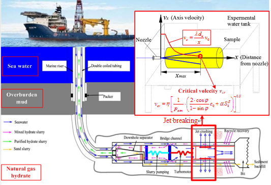
1. Introduction
2. Experiment Equipment and Method
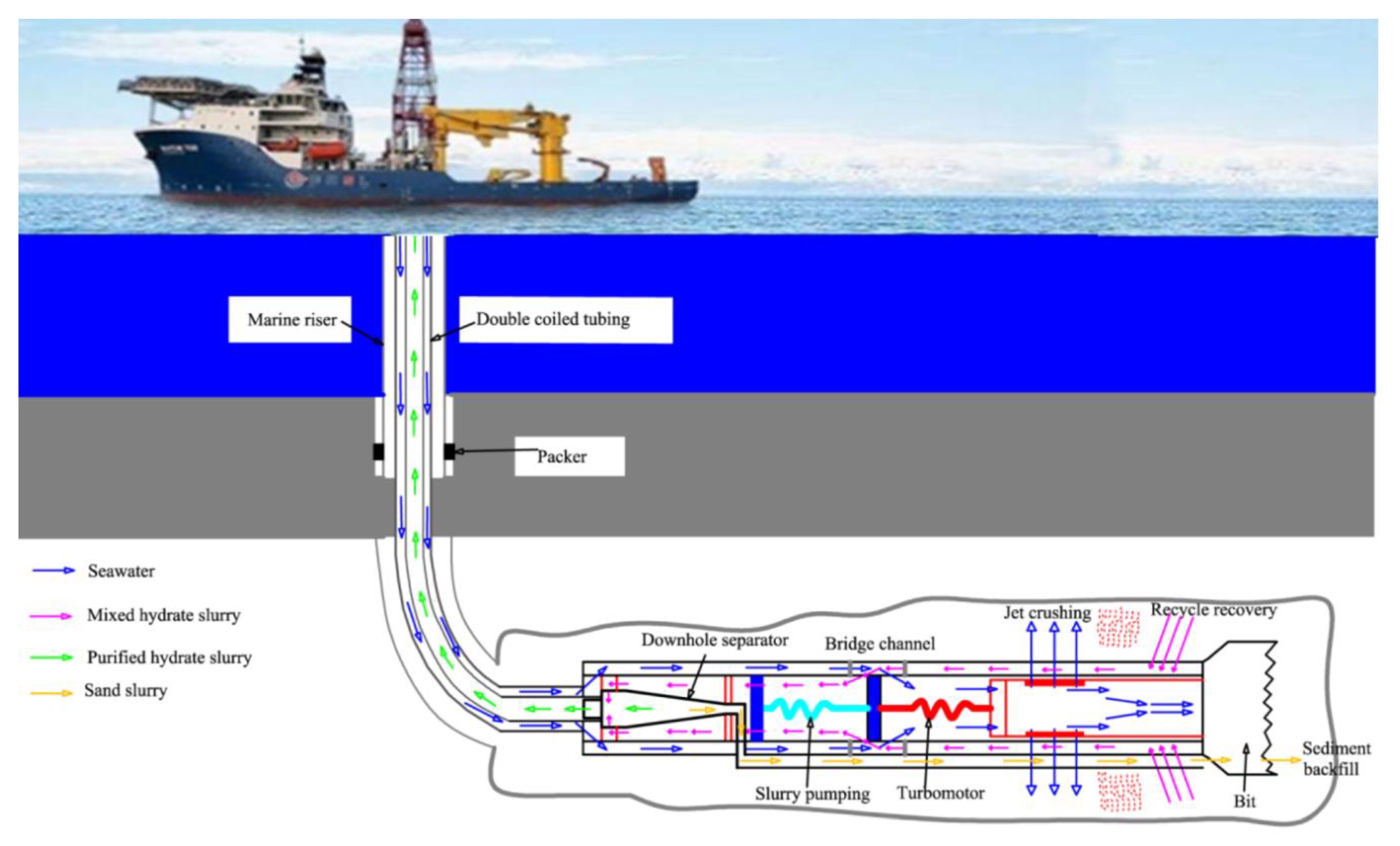
2.1. Experimemt Apparatus
2.2. Sample Preparation
2.3. Experimemt Procedure
3. Results and Discussion
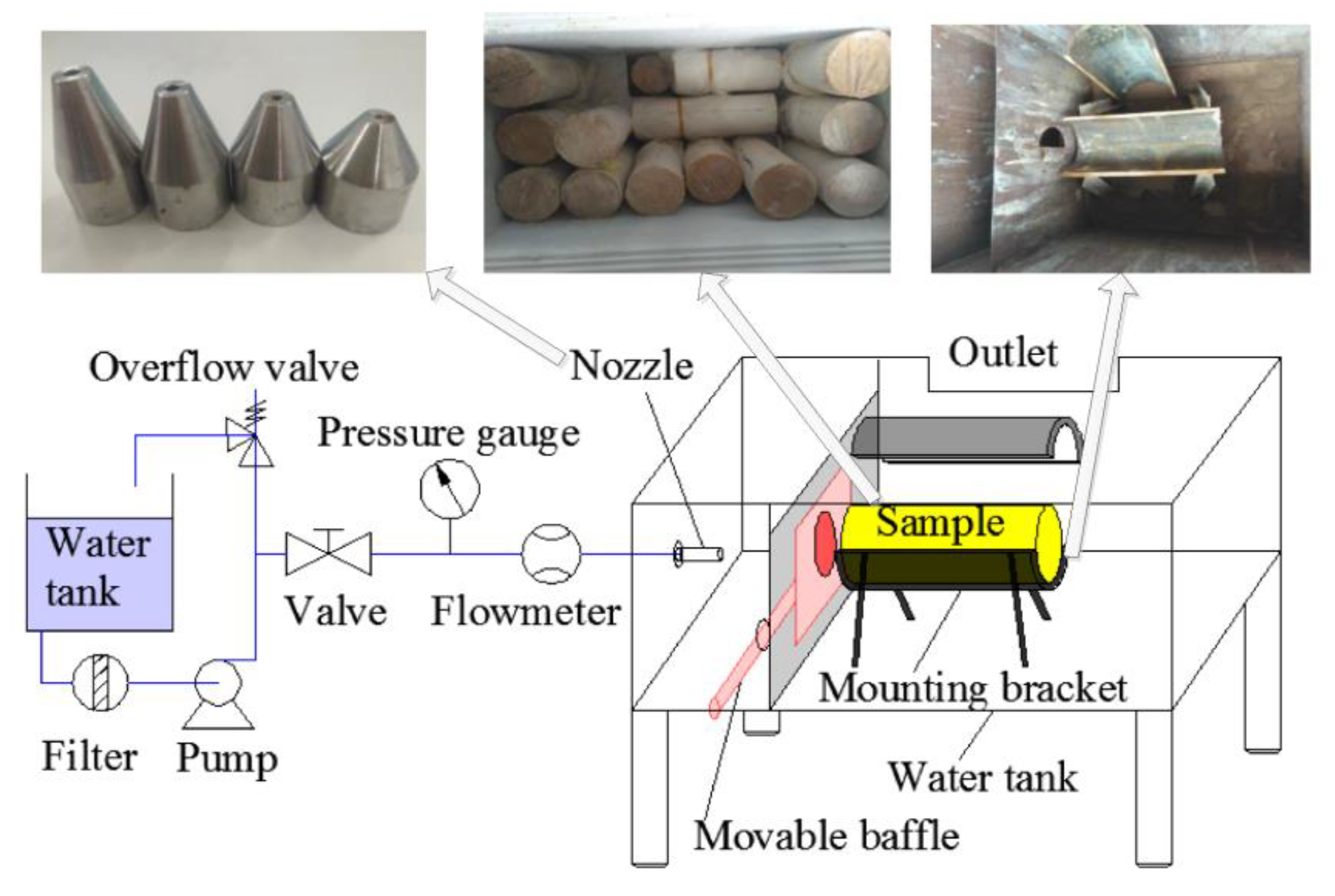
3.1. Ultimate Breaking Time of the NGH Water Jet Breaking Process
3.2. Ultimate Breaking Distance of NGH Breaking by Water Jet
3.3. Critical Velocity of the NGH
4. Conclusions
Author Contributions
Funding
Conflicts of Interest
References
- Makogon, Y.F. Natural gas hydrates—A promising source of energy. J. Nat. Gas. Sci. Eng. 2010, 2, 49–59. [Google Scholar] [CrossRef]
- Chong, Z.R.; Yang, S.H.B.; Babu, P.; Linga, P.; Li, X.-S. Review of natural gas hydrates as an energy resource: Prospects and challenges. Appl. Energy 2016, 162, 1633–1652. [Google Scholar] [CrossRef]
- Boswell, R.; Collett, T.S. Current perspectives on gas hydrate resources. Energy Env. Sci. 2011, 4, 1206–1215. [Google Scholar] [CrossRef]
- Pinero, E.; Marquardt, M.; Hensen, C.; Haeckel, M.; Wallmann, K. Estimation of the global inventory of methane hydrates in marine sediments using transfer functions. Biogeosciences 2013, 10, 959–975. [Google Scholar] [CrossRef]
- Boswell, R.; Collett, T. The Gas Hydrates Resource Pyramid: Fire in the ice, methane hydrate newsletter. US Dep. Energy 2006, 6, 5–7. [Google Scholar]
- Tamaki, M.; Fujii, T.; Suzuki, K. Characterization and Prediction of the Gas Hydrate Reservoir at the Second Offshore Gas Production Test Site in the Eastern Nankai Trough, Japan. Energies 2017, 10, 1678. [Google Scholar] [CrossRef]
- Konno, Y.; Fujii, T.; Sato, A.; Akamine, K.; Naiki, M.; Masuda, Y.; Yamamoto, K.; Nagao, J. Key Findings of the World’s First Offshore Methane Hydrate Production Test off the Coast of Japan: Toward Future Commercial Production. Energy Fuels 2017, 31, 2607–2616. [Google Scholar] [CrossRef]
- Arata, N.; Sukizaki, S.; Denda, A.; Awashima, Y.; Okada, Y. Overview of the R&D for an Environmental Impact Assessment on Japan’s Methane Hydrate R&D Program in Phase-1. J. Jpn. Assoc. Pet. Technol. 2009, 74, 350–359. [Google Scholar]
- Wu, X.H.W.; Liu, W. Assessment of global gas hydrate resource potential and progress of production. Mar. Geol. Front. 2018, 33, 63–78. [Google Scholar]
- Li, H.; Wei, N.; Jiang, L.; Zhao, J.; Cui, Z.; Sun, W.; Zhang, L.; Zhou, S.; Xu, H.; Zhang, X.; et al. Evaluation of Experimental Setup and Procedure for Rapid Preparation of Natural Gas Hydrate. Energies 2020, 13, 531. [Google Scholar] [CrossRef]
- Wu, S.W.J. Reflections on the Successful Trial Production of Natural Gas Hydrate in Shenhu Sea Area of South China Sea. Chin. Sci. Bull. 2018, 63, 2–8. [Google Scholar] [CrossRef]
- Li, G.; Moridis, G.J.; Zhang, K.; Li, X.-S. Evaluation of Gas Production Potential from Marine Gas Hydrate Deposits in Shenhu Area of South China Sea. Energy Fuels 2010, 24, 6018–6033. [Google Scholar] [CrossRef]
- Moridis, G.; Reagan, M.T.; Boyle, K.L.; Zhang, K. Evaluation of the Gas Production Potential of Some Particularly Challenging Types of Oceanic Hydrate Deposits. Transp. Porous Media 2011, 90, 269–299. [Google Scholar] [CrossRef]
- Zhou, S.C.W.; Li, Q. Research on the solid fluidization well testing and production for shallow non-diagenetic natural gas hydrate in deep water area. China Offshore Oil Gas. 2017, 29, 1–8. [Google Scholar]
- Wu, X.; Liang, Q.; Ma, Y.; Shi, Y.; Xia, Z.; Liu, L.; Haeckel, M. Submarine Landslides and their Distribution in the Gas Hydrate Area on the North Slope of the South China Sea. Energies 2018, 11, 3481. [Google Scholar] [CrossRef]
- First successful trial collection of natural gas hydrate in China. Geol. China 2017, 44, 620–621.
- Qiu, S.; Wang, G.; Wang, L.; Fang, X. A Downhole Hydrocyclone for the Recovery of Natural Gas Hydrates and Desanding: The CFD Simulation of the Flow Field and Separation Performance. Energies 2019, 12, 3257. [Google Scholar] [CrossRef]
- Zhou, S.; Chen, W.; Li, Q. Green production technology of deep water shallow gas hydrate with solid fluidization method. China Offshore Oil Gas. 2014, 26, 1–7. [Google Scholar]
- Pan, D.C.C.; Yang, L.; Jin, C.; Li, X.; Liu, S.; Chen, Y.; Zhu, J. Physical simulation experiment system for jet erosion of natural gas hydrate. Explor. Eng. Rock Soil Drill. Tunn. 2018, 45, 35–39. [Google Scholar]
- Chen, C.; Pan, D.; Yang, L.; Zhang, H.; Li, B.; Jin, C.; Li, X.; Cheng, Y.; Zhong, X. Investigation into the Water Jet Erosion Efficiency of Hydrate-Bearing Sediments Based on the Arbitrary Lagrangian-Eulerian Method. Appl. Sci. 2019, 9, 182. [Google Scholar] [CrossRef]
- Yang, L. Study on the Breaking Process of Marine Hydrate Subjected to High Pressure Water Jet and the Production Increase of Marine Hydrate Reservoirs Reconstruction; Jilin University: Changchun, China, 2018. [Google Scholar]
- Wang, G.; Zhong, L.; Zhou, S.; Liu, Q.; Li, Q.; Fu, Q.; Wang, L.; Huang, R.; Wang, G.; Li, X. Jet breaking tools for natural gas hydrate exploitation and their support technologies. Nat. Gas. Ind. B 2018, 5, 312–318. [Google Scholar] [CrossRef]
- Wang, G.; Huang, R.; Zhong, L.; Wang, L.; Zhou, S.; Liu, Q. An optimal design of crushing parameters of marine gas hydrate reservoirs in solid fluidization exploitation. Nat. Gas. Ind. B 2019, 6, 257–261. [Google Scholar] [CrossRef]
- Wang, L.; Wang, G.; Mao, L.; Zhou, S.; Zhong, L. Experimental research on the breaking effect of natural gas hydrate sediment for water jet and engineering applications. J. Pet. Sci. Eng. 2020, 184, 106553. [Google Scholar] [CrossRef]
- Lv, X.; Shi, B.; Zhou, S.; Wang, S.; Huang, W.; Sun, X. Study on the Decomposition Mechanism of Natural Gas Hydrate Particles and Its Microscopic Agglomeration Characteristics. Appl. Sci. 2018, 8, 2464. [Google Scholar] [CrossRef]
- Dvorkin, J.; Helgerud, M.B.; Waite, W.; Kirby, S.H.; Nur, A. Introduction to Physical Properties and Elasticity Models. In Asia-Pacific Coasts and Their Management; Springer Science and Business Media LLC: Berlin/Heidelberg, Germany, 2003; Volume 5, pp. 245–260. [Google Scholar]
- Cox, J.L. Natural Gas. Hydrates: Properties, Occurrence and Recovery; US Department of Energy: Washington, DC, USA, 1983.
- Stern, L.A.; Kirby, S.H.; Durham, W.B. Polycrystalline Methane Hydrate: Synthesis from Superheated Ice, and Low-Temperature Mechanical Properties. Energy Fuels 1998, 12, 201–211. [Google Scholar] [CrossRef]
- Durham, W.B.; Stern, L.A.; Kirby, S.H. Ductile flow of methane hydrate. Can. J. Phys. 2003, 81, 373–380. [Google Scholar] [CrossRef]
- Cao, P.; Wu, J.; Zhang, Z.; Fang, B.; Ning, F. Mechanical Properties of Methane Hydrate: Intrinsic Differences from Ice. J. Phys. Chem. C 2018, 122, 29081–29093. [Google Scholar] [CrossRef]
- Zhang, X.; Wang, S.; Li, Q.; Zhao, J.; Wang, A. Experimental study of mechanical properties of gas hydrate deposits. Rock Soil Mech. 2010, 31, 3069–3074. [Google Scholar]
- Winters, W.; Pecher, I.A.; Waite, W.; Mason, D.H. Physical properties and rock physics models of sediment containing natural and laboratory-formed methane gas hydrate. Am. Min. 2004, 89, 1221–1227. [Google Scholar] [CrossRef]
- Kuang, Y.; Yang, L.; Li, Q.; Lv, X.; Li, Y.; Yu, B.; Leng, S.; Song, Y.; Zhao, J. Physical characteristic analysis of unconsolidated sediments containing gas hydrate recovered from the Shenhu Area of the South China sea. J. Pet. Sci. Eng. 2019, 181, 106173. [Google Scholar] [CrossRef]
- Ho, C.E. Turbulent Fluid Jet Excavation in Cohesive Soil: With Particular Application to Jet Grouting; Massachusetts Institute of Technology: Cambridge, MA, USA, 2005. [Google Scholar]
- Rajaratnam, N. Turbulent Jets. Dev. Water Sci. 1976, 5, 77–82. [Google Scholar]
- Dabbagh, A.A.; Gonzalez, A.S.; Pena, A.S. Soil Erosion by a Continuous Water Jet. Soils Found 2002, 42, 1–13. [Google Scholar] [CrossRef]
- Miyazaki, K.; Temma, N.; Aoki, K.; Yamaguchi, T. A Nonlinear Elastic Model for Triaxial Compressive Properties of Artificial Methane-Hydrate-Bearing Sediment Samples. Energies 2012, 5, 4057–4075. [Google Scholar] [CrossRef]


| Experimental Serial Number | Saturation (%) | Nozzle Diameter (mm) | Jet Pressure (MPa) |
|---|---|---|---|
| 1 | 20 | 1.5 | 2.5 |
| 2 | 20 | 2.0 | 5 |
| 3 | 20 | 2.5 | 7.5 |
| 4 | 20 | 3.0 | 10 |
| 5 | 40 | 1.5 | 5 |
| 6 | 40 | 2.0 | 2.5 |
| 7 | 40 | 2.5 | 10 |
| 8 | 40 | 3.0 | 7.5 |
| 9 | 60 | 1.5 | 7.5 |
| 10 | 60 | 2.0 | 10 |
| 11 | 60 | 2.5 | 2.5 |
| 12 | 60 | 3.0 | 5 |
| 13 | 80 | 1.5 | 10 |
| 14 | 80 | 2.0 | 7.5 |
| 15 | 80 | 2.5 | 5 |
| 16 | 80 | 3.0 | 2.5 |
| Parameter | Factor A | Factor B | Factor C |
|---|---|---|---|
| Saturation | Jet Pressure | Nozzle Diameter | |
| K1 | 230.5 (20%) | 101.5 (2.5 MPa) | 107.5 (1.5 mm) |
| K2 | 179 (40%) | 144 (5.0 MPa) | 138.75 (2.0 mm) |
| K3 | 126.5 (60%) | 183.25 (7.5 MPa) | 179 (2.5 mm) |
| K4 | 109.25 (80%) | 216.5 (10.0 MPa) | 220 (3.0 mm) |
| R | 121.25 | 115 | 112.5 |
© 2020 by the authors. Licensee MDPI, Basel, Switzerland. This article is an open access article distributed under the terms and conditions of the Creative Commons Attribution (CC BY) license (http://creativecommons.org/licenses/by/4.0/).
Share and Cite
Wang, L.; Wang, G. Experimental and Theoretical Study on the Critical Breaking Velocity of Marine Natural Gas Hydrate Sediments Breaking by Water Jet. Energies 2020, 13, 1725. https://doi.org/10.3390/en13071725
Wang L, Wang G. Experimental and Theoretical Study on the Critical Breaking Velocity of Marine Natural Gas Hydrate Sediments Breaking by Water Jet. Energies. 2020; 13(7):1725. https://doi.org/10.3390/en13071725
Chicago/Turabian StyleWang, Leizhen, and Guorong Wang. 2020. "Experimental and Theoretical Study on the Critical Breaking Velocity of Marine Natural Gas Hydrate Sediments Breaking by Water Jet" Energies 13, no. 7: 1725. https://doi.org/10.3390/en13071725
APA StyleWang, L., & Wang, G. (2020). Experimental and Theoretical Study on the Critical Breaking Velocity of Marine Natural Gas Hydrate Sediments Breaking by Water Jet. Energies, 13(7), 1725. https://doi.org/10.3390/en13071725