1. Introduction
In recent years, thanks to the achievements of materials science, it is becoming possible to produce active components of an electromechanical converter from giant magnetostrictive materials (GMM). The GMM have a special property of exhibiting coupling between macroscopic mechanical (stress σ and strain ε) and magnetic variables (field intensity
H and flux density
B) [
1,
2,
3]. This coupling is used to obtain a macroscopic extension known as magnetostriction. In general, the term magnetostriction refers to strains generated during the paramagnetic to ferromagnetic phase transition, i.e., spontaneous magnetostriction, or in response to an applied field, which constitutes magnetomechanical coupling. The magnetostriction occurs in the most ferromagnetic materials and leads to many effects [
1,
2,
3]. The characteristic behavior of the magnetostrictive materials is caused by the reorientation of the magnetic dipoles within the material under the presence of the external magnetic field. This reorientation leads to shape change in sample dimensions, in the direction of the applied field, i.e., the Joule effect. The Joule effect corresponds to a longitudinal change in length due to the applied magnetic field. A positive Joule magnetostriction means elongation, whereas a negative magnetostriction indicates contraction. The Villari effect is the inverse of the Joule effect and corresponds to the change in magnetization due to the stress applied to the material. The Joule effect makes the GMM usable in actuation, while the Villari effect is useful for sensing. The GMM are widely employed nowadays as the main components of actuators [
4,
5,
6], sensors [
1,
7,
8], energy harvesters [
9,
10] or some other devices [
1,
3,
11,
12]. The GMM can also be used to build unconventional motors, so-called vibromotors [
13,
14].
The most popular kind of GMM is Terfenol-D, an alloy made of iron (Fe) and two rare earth elements: terbium (Tb) and dysprosium (Dy). Therefore, we concentrate on the system with a rod made of Terfenol-D. The main area where Terfenol-D is applied is the construction of actuators and sensors. Giant magnetostrictive actuators (GMAs) are used in high-class industrial devices (linear motors, micropumps, microvalves, micropositioners, etc.,), biomedical applications and the arms industry [
1,
3].
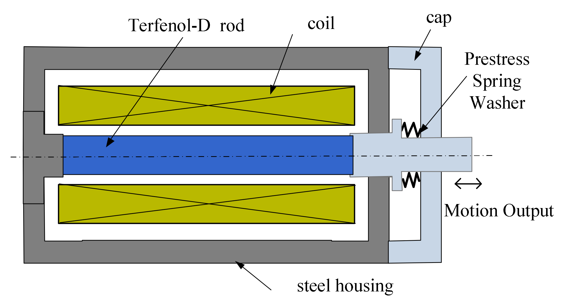
The simplest form of the GMA consists of a cylindrical rod which is magnetically excited by the coil surrounding the rod to generate strain and force.
Figure 1. shows a typical structure of the GMA that has been considered in this paper. The magnetostrictive rod (Terfenol-D) is coaxially installed in the center of the surrounding solenoid coil. The GMM rod needs pre-pressure produced by a pre-stress spring, because the magnetostrictive strain of the Terfenol-D rod can be enhanced by the axial compressive pre-stress σ
0 [
1,
15]. Thus, when a sufficient magnetic field is applied along the axis of the rod under the pre-stress, all the magnetic domains will rotate in the axial direction causing greater relative elongation, i.e., the magnetostrictive strain in the conventional sense [
16]. In addition, the value of the maximum magnetostrictive strain increases with the increase of the compressive pre-stress [
1,
16].
The GMA exhibits nonlinear behavior and magneto-mechanical coupling characteristics. In order to design the GMAs, accurate modeling of their characteristics is necessary. Usually, to determine the distribution of the magnetic and mechanical displacement fields, the finite element method (FEM) is used. Several studies about the use of FEM to solve nonlinear electro-magneto-mechanical equations and analyze the characteristics of the GMA have been published [
12]. As examples, in [
17,
18], the authors implemented nonlinear FEM in static or quasi-static conditions. Fully coupled nonlinear magneto-elastic models for magnetostrictive transducers are presented in [
19,
20]. However, the resulting model equations presented in [
19,
20] are coded into the commercial finite element package COMSOL, which is used for meshing and global assembly of matrices.
The paper presents a finite element (FE) coupled model of the GMA. The proposed model consists of equations of the magnetic and displacement fields. The equations are coupled through a nonlinear magneto-mechanical constitutive law for a magnetostrictive rod. The model is considered to be 2D axisymmetric. In the developed model, we apply the concept of edge element calculations for a magnetic field and a special method of force calculations as well as using the modified Newton–Raphson algorithm to solve the nonlinear equations.
The paper is organized as follows:
Section 2 describes the magneto-mechanical equations, while
Section 3 presents the FE model of an axisymmetric electromechanical converter with a magnetostrictive rod.
Section 4 shows validation of the FE model with an appropriate measurement setup. The article ends with conclusions.
2. Magnetomechanical Equations
The magnetomechanical effect consists of two coupled mechanisms: the applied stresses cause the magnetic moments to rotate, thus changing the magnetization, and the rotation of the moments to align with the applied field generates strain in the material. In the magnetostrictive material, the strain
ε and the magnetic flux density
B are functions of the stress
σ and the magnetic field intensity
H. The behavior of the magnetostrictive materials is described by nonlinear relations,
ε =
ε(σ,
H),
B =
B(σ,
H) [
1]. Here, the total strain tensor
ε is the sum of the elastic strain
εe and the magnetostrictive strain
εms,
Only the elastic strain contributes to mechanical stress [
1,
4]. The magnetostrictive strain describes the relative change in length of the material from the ordered but unaligned state to the state where domains are aligned.
Very often, the magnetostrictive strain is modeled using the linear constitutive relation,
εms = dH, where
d is the piezo-magnetic strain matrix. However, in reality, the relation between the strain
εms and intensity
H is nonlinear. The magnetostrictive strain exhibits a quadratic dependence on magnetization in a manner analogous to a quadratic polarization dependence exhibited by electrostrictive materials and piezoelectric compounds in high drive regimes [
3,
21]. This quadratic dependence is described by the magnetostrictive strain represented by the following deviatoric tensor:
where λ
s is the saturation magnetostriction constant,
Ms is the saturation magnetization and
M is the magnetization vector.
In the applied 2D axisymmetric model, the components of the strain tensor are defined as follows:
where ε
ms,u and
Mu represent the
u-th (
u =
r,
z) component of the tensor
εms and the vector
M respectively.
The vector of the magnetization
M can be defined as
where ν
0 is the reluctivity of free space and
ν is the reluctivity.
Saturation magnetostriction quantifies strains due to magneto-mechanical coupling and provides a metric for the characterization of the transduction capabilities of the material. The saturation magnetostriction attains different values under different pre-stress conditions. In the case of GMM, the saturation magnetostriction value under compression pre-stress is larger than the value under tension pre-stress; moreover, it increases with the increase of the compression pre-stress [
1,
3].
The saturation magnetization determines to what extent the magnetic moments can reorient in response to the applied field; therefore, to achieve strong transduction, its quantity should be large. Generally, the saturation magnetization is independent of the pre-stress [
3].
According to Hook’s law, the stress tensor
σ is linked to the strain tensor
εe by the elastic constitutive law:
where
C is the stiffness matrix [
4,
15] widely used in structural analysis.
Certain Terfenol-D compositions can be treated as isotropic materials [
1]. In such cases, the constitutive law can be written using the Young’s modulus of elasticity
E and Poisson’s ratio ν [
4,
22].
The stress tensor
σ is linked to the strain tensor
εe, while
εe is expressed in terms of the elastic displacement vector
ue. The strain displacement relations can be written in the following form:
where
D is the displacement gradient tensor [
4,
22] and
u,
ums represent the total displacement vector and the magnetostrictive displacement vector respectively.
Using the strain displacement relations (6), constitutive law (5) and creating a force balance condition under static equilibrium, we obtain the following governing equation:
where
f is the external force vector,
fm =
fm(
B) is the magnetic force vector and
fms =
fms(
σ,
B) is the magnetostrictive force vector that depends on the stress
σ and magnetic flux density
B.
In the considered magnetomechanical problem, Equation (7) is coupled with the equations of the magnetic field and relations that express forces using magnetic field distribution. Here, the magnetic vector potential formulation is applied (
B = curl
A). Thus, the equation describing the magnetic vector potential
A for a given current density
J is as follows:
where
Jms =
Jms(
σ,
B) is the magnetizing current induced by mechanical stress (Villari effect), representing the influence of magnetostriction on the magnetic field. In the calculations, the eddy currents are neglected, and
J represents the density of a given current in the coil.
One could easily notice that (7) and (8) are coupled with each other through the sources.
3. Model of the GMA
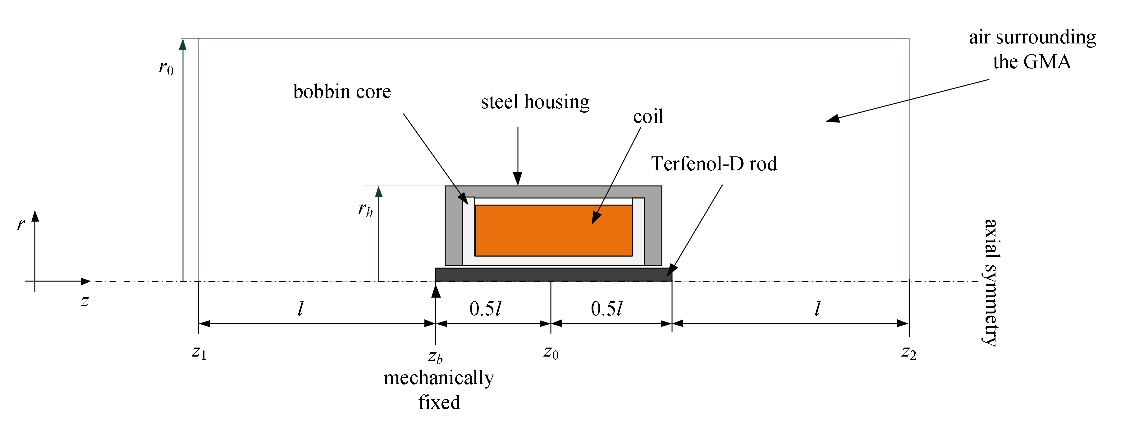
The brittle nature of Terfenol-D and its poor machinability restricts its availability to geometries like cylindrical rods. The GMA contains components that are all cylindrical in nature with axisymmetric geometry that is well adapted to a built-in magnetostrictive transducer. The computations are performed in an axial symmetry domain with cylindrical coordinates (
r,
z, ϑ)—see
Figure 2. The fundamental dimensions of the considered GMA are shown in
Figure 2.
The actuator is surrounded by empty space and therefore it can be assumed that in the outer cylindrical surface
r =
r0 = 2.5
rh and plane surfaces
z =
z1 = z
0 − l.5
l;
z =
z2 =
z0 + l.5
l, the components of magnetic flux density are equal to zero. The boundaries for the region with the mechanical displacement field are placed off the contour surface of the magnetostrictive rod, i.e., the Terfenol-D rod. The boundary conditions for the Terfenol-D rod are of a symmetrical type and free (unconstrained) for the side situated on the symmetry axis. The Terfenol-D rod is one-sidedly, mechanically attached to the bottom
z =
zb, see
Figure 2. Thus, in the computations, the distortions of the steel housing and coil are neglected.
In the case of a clamped Terfenol-D rod, the total displacement remains zero,
u = 0, since the magnetostrictive strain is compensated by elastic strain. Thus, in (5),
εe = −
εms and the second component of (5) represents the blocked stress
σblock of the material,
The blocked force refers to the maximum value of the magnetostrictive strain that can be applied to a sample of magnetostrictive materials. However, the blocked force can be calculated for each value of magnetic field intensity,
where
ST is the vector of one nonzero component related only to the cross-sectional area of the GMM rod.
Magnetomechanical Equations (7), (8) are solved using the FE method, where the same mesh of elements is used for both magnetic and elastic computations. Therefore, the deformations determined on the mechanical grid accompanied by a change of dimensions are automatically transferred to a model describing the magnetic field.
In the FE method, Equations (7), (8) are represented by a matrix equation, which can be expressed in the following matrix form:
where
S and
K are the magnetic and mechanical stiffness matrices, respectively,
Θ is the current source vector,
Θms(
σ,
B) is the magnetostrictive current source vector, and
φ is the vector of the edge value φ
i of the potential
A.
For the oriented edge
PiPj, the edge value is equal to the line integral of
A on
PiPj. The edge value of
A for the edge
PiPj can be considered as a loop flux in the loop around
PiPj. The considered model is discretized using the element presented in
Figure 3.
In the case of 3D, this element is a curved, 5-faced prism, but if we consider an axisymmetric model, then Δϑ = 2π, y = r and A = 1ϑAϑ. For a node of coordinates z = zi, r = ri, φi = 2πriAϑ(zi, ri), where Aϑ is the azimuthal component of the vector A. Taking advantage of the geometrical structure of the considered GMA, the calculations are performed in an axial-symmetric domain with cylindrical coordinates (r, z, ϑ).
The vector U in (12) represents nodal displacement in the direction of r and the z axis. F is the vector of external forces, Fm(B) is the magnetic force vector, which is given by the local application of the virtual work principle and Fms(σ,B) is the vector of nodal magnetostrictive forces.
In the formulations of the above Equations (11), (12), we applied the idea presented in [
17]. This idea was modified by applying the concept of edge element calculations for a magnetic field and by a special method of force calculations
Fm(
B). The modifications of [
17] consisted of considering the discretization grid as a grid composed of the elements shown in
Figure 3. In the formulations of the magnetic force calculations, we applied the approach presented in [
23]. The idea of the global force calculations presented in [
23] was adopted for the calculations of force acting on each separately considered element.
The coupled problem was considered as an iterative process of subsequent magnetic and mechanical finite element calculations. This is a weak approach to coupling, as opposed to a strong coupling based on simultaneous iterations. The FE equations can be solved using a cascade procedure similar to the approach presented in [
24].
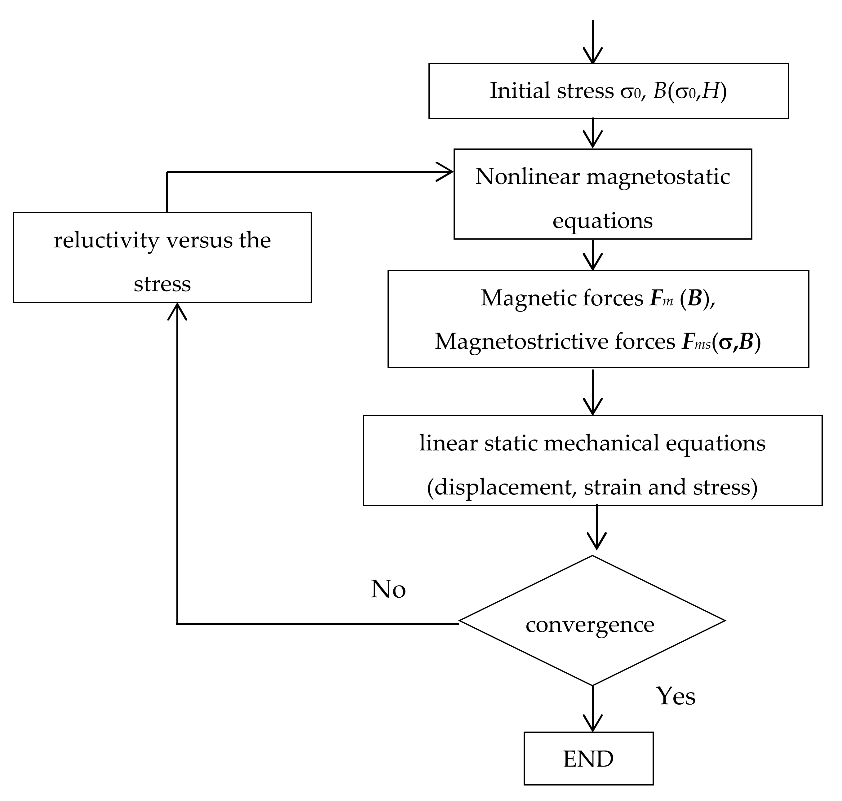
The use of the personally developed software allows the introduction of the coupling by the use of the experimental data, which were obtained from a specially designed unique test stand for the experimental investigation characterization of Terfenol-D rods. Moreover, we calculated the
B(σ
0,
H) characteristics according to the applied pre-stress σ
0 using our in-house developed software [
15]. First, we assumed the initial stress σ
0 and then we solved nonlinear magnetostatic equations (see
Figure 4).
The modified Newton–Raphson algorithm was applied to solve the nonlinear equations. We used some ideas presented in paper [
25]. In the applied method, the classical Jacobian matrix is replaced by its simplified representations
SsJ. In order to obtain
SsJ, the reluctivity
ν in the description entries of formulas of the matrix is replaced by d
H/d
B, i.e., by d(|
B|ν)/d(|
B|). The increments, i.e.,
SsJ−1r(k), are calculated using the Cholesky decomposition procedure. Thus, the matrix
SsJ is expressed by the product of triangular matrices, i.e.,
SsJ =
LLT. In the applied algorithm, the matrices
SsJ and
L are calculated only for the first five iteration steps and for the (
k+1)-th step, if |
r(k)|/|
r(k−1)| > 0.99 where
r is the residual vector.
In the next step, the magnetic forces
Fm (
B) are calculated using the local application of the virtual work principle and the magnetostrictive forces
Fms(
σ,
B) are calculated using a similar approach to the one presented in [
24]. Then, mechanical equations are solved.
The calculations were performed for a grid with different numbers of elements. The considered GMA was divided into the elements shown in
Figure 3 but was adapted to the axisymmetric model. The results for a model of 120,000 elements are presented in the next section.
4. Computed and Experimental Results
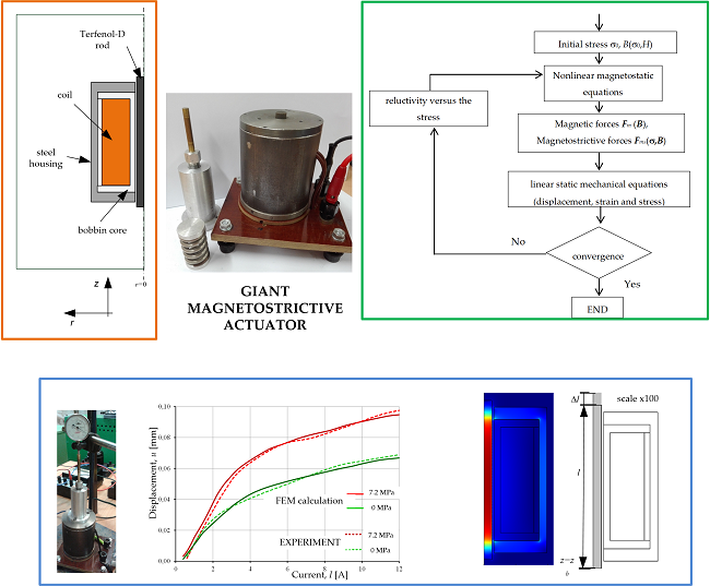
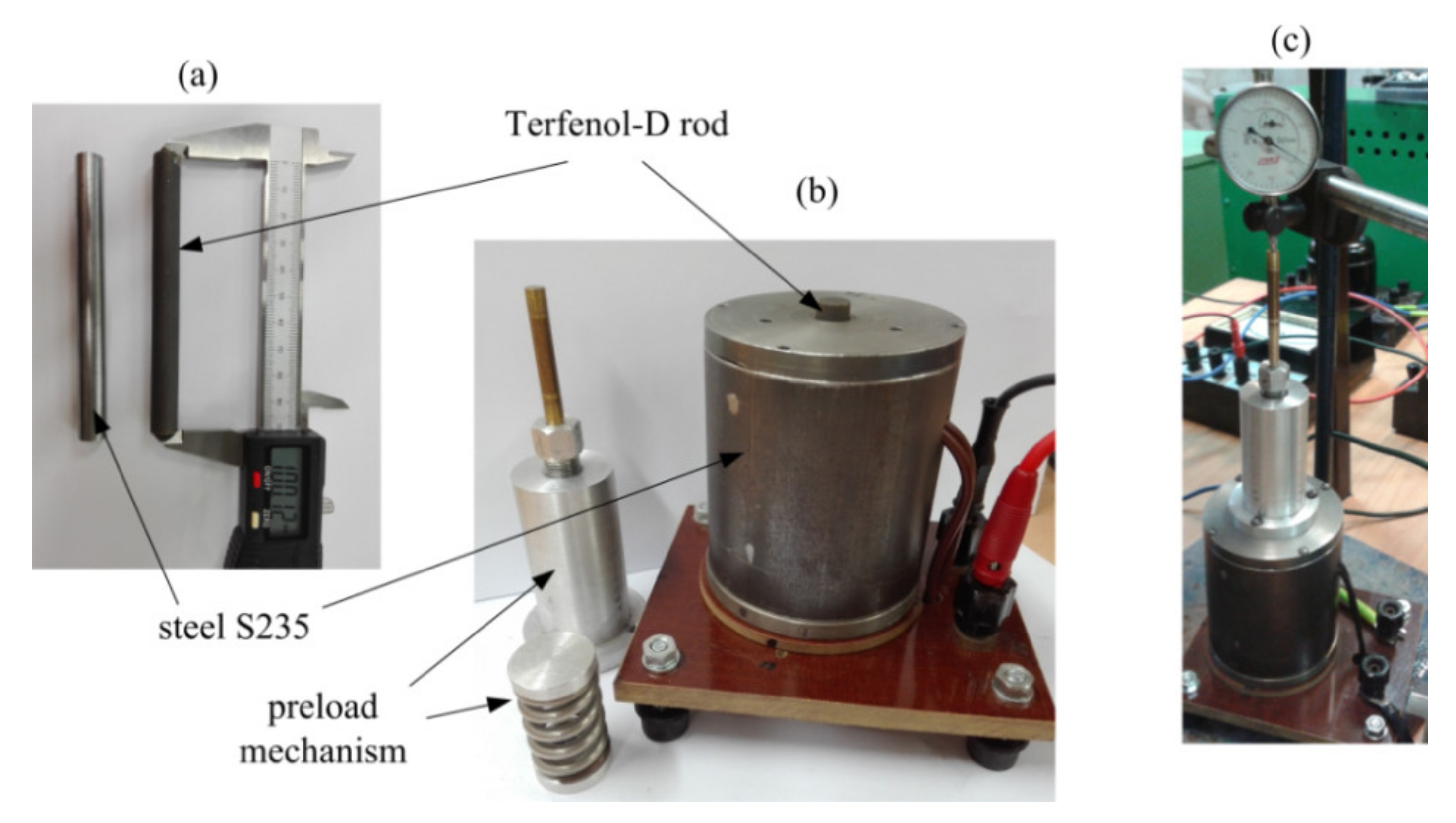
The FE model presented above was applied for the analysis of the converter specially prepared for experimental testing (
Figure 5b). The magnetostrictive rod of the converter was made of Terfenol-D. The length of the rod was 100 mm and the diameter was 10 mm (
Figure 5a). When designing the test stand, various techniques to measure small displacements of the rod were taken into account. To obtain convergent displacement measurements, we used, among others, a micrometer sensor (
Figure 5c). A laser sensor was also applied.
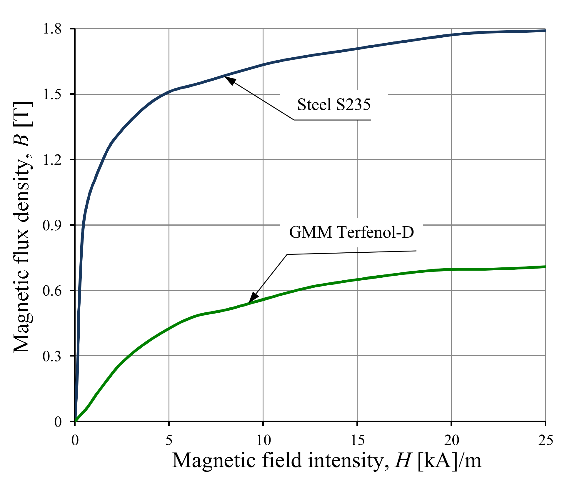
The results of the FE method were used in the calculations of the selected field and integral quantities, e.g., stresses, strains, magnetic field density, displacements and blocked force. It was assumed that a GMA was supplied by a DC power source. It should be noted that the calculations were preceded by the measurement of nonlinear characteristics of the magnetic materials of the tested converter. The magnetic measurement was performed in an open magnetic circuit [
26]. Demagnetizing factors for a cylindrical Terfenol D rod were defined using the ballistic method [
26]. The measured magnetization characteristic is presented in
Figure 6.
The performance of a magnetostrictive converter strongly depends on the initial values of magnetic field intensity and stresses. Thus, these values should be selected appropriately. Studying coupled magnetomechanical properties of a magnetostrictive converter ought to be very thorough and should take place during its operation, since the expected operating range is obtained by applying mechanical pre-stress. The authors previously computed the
B(σ
0,
H) characteristics according to the applied pre-stress σ
0, using their own in-house developed software [
15]. The calculations were performed for the properties of Terfenol-D, a description of which was found in the literature [
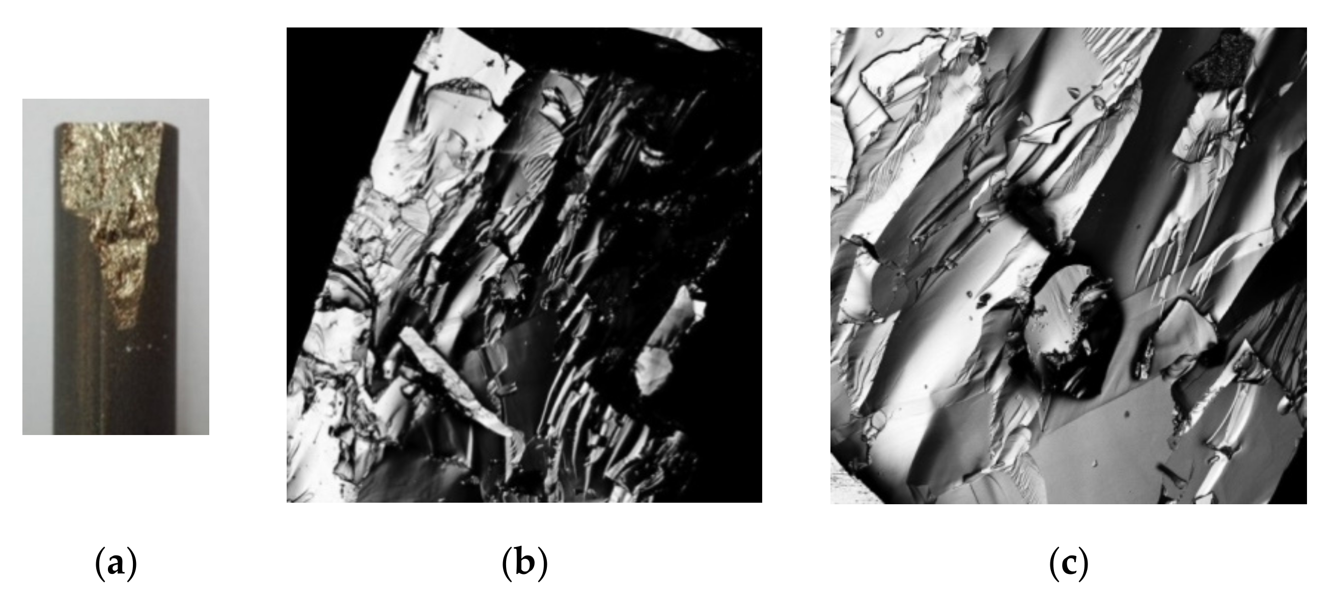
15]. Here, in order to fully recognize the properties, additional tests were completed, e.g., the tested rod was subjected to strong stress. Monolithic Terfenol-D is very brittle and can easily be damaged. The damaged sample of the Terfenol-D rod is presented in
Figure 7. A laser scanning confocal microscope (LSM) (LSM 710 Zeiss) was used to characterize the Terfenol-D surface [
27].
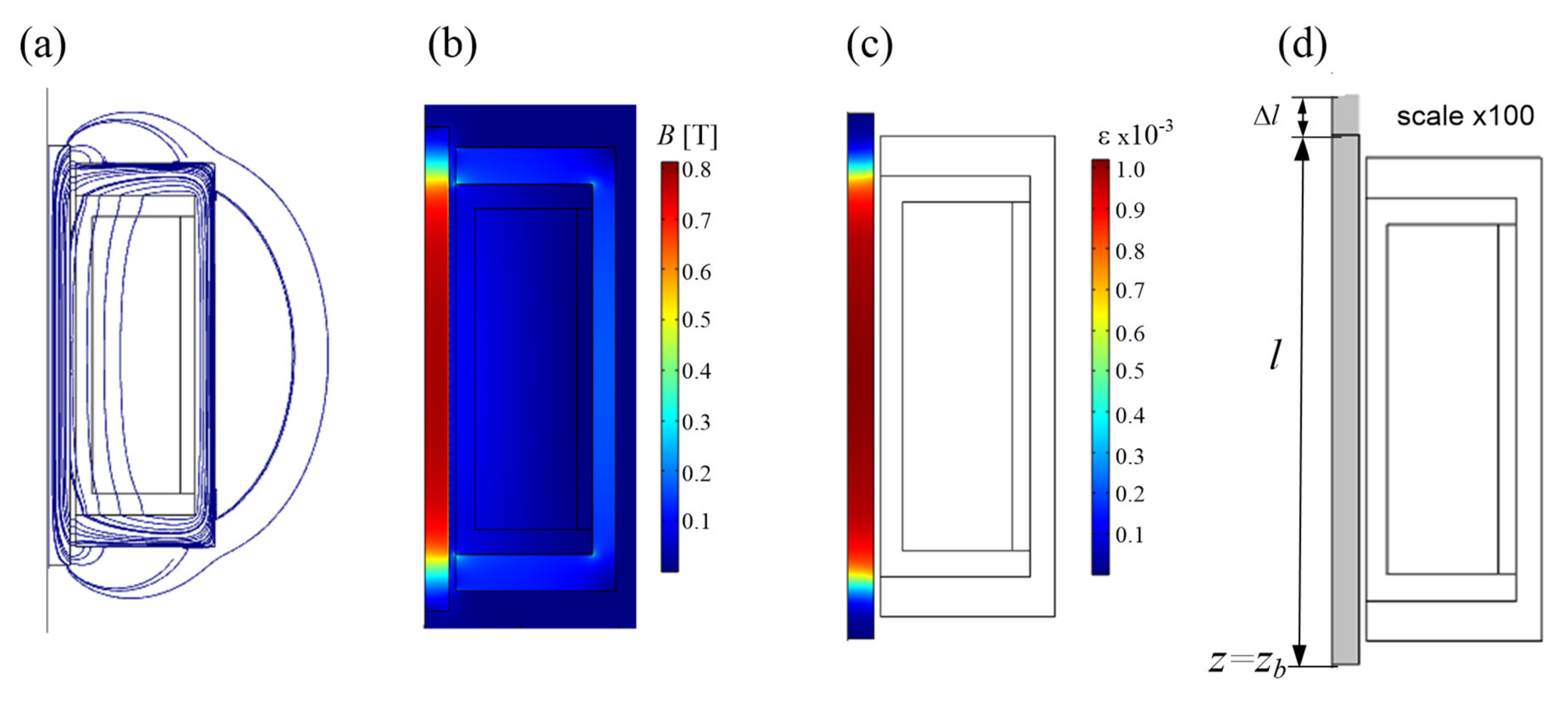
The calculated magnetic field line and magnetic flux density distribution for the GMA at a pre-stress of 7.2 MPa and a supply current of 6 A have been shown in
Figure 8a,b. It is well known that for the correct operation of a magnetostrictive converter, the most important factors are distributions of strain and a displacement field in a Terfenol-D rod. These distributions have been shown in
Figure 8c,d. It has been assumed that the rod is mechanically fixed, however, it can move freely.
The presented distributions of magnetic field shows that the magnetic field is concentrated at the center of the rod. The intensity and uniformity of the magnetic field are the key factors that influence the performance of a GMA. The magnetic field changes direction at the ends of the rod. On the basis of the presented results, it can be seen that the total strain is concentrated at the center of the rod due to the high concentration of the magnetic field in the middle of the rod.
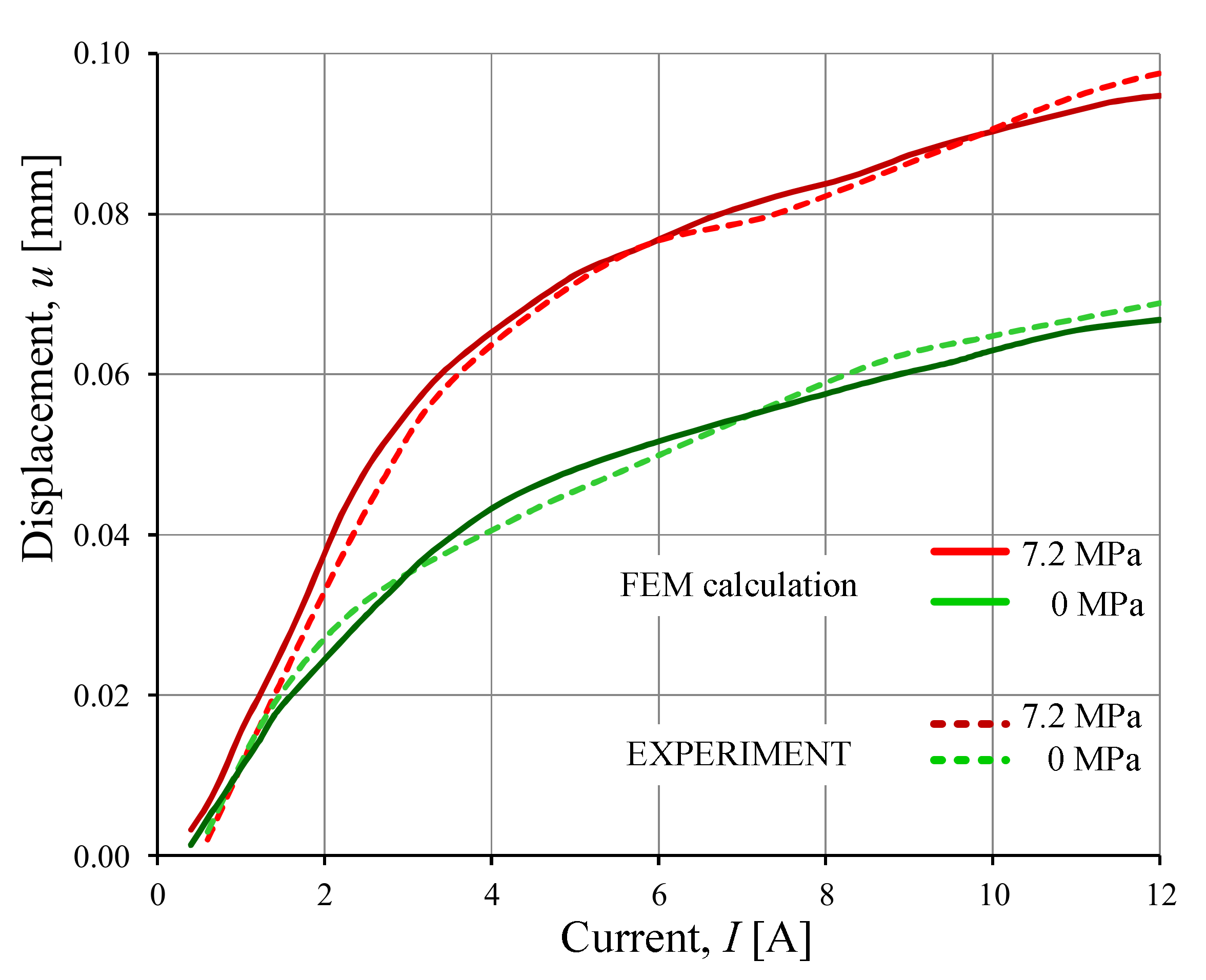
In
Figure 9, the selected results of calculations and measurements are given. The calculated and measured values of the output displacement of the GMA as a function of supplied current are shown (see
Figure 9).
When we modeled the magnetostrictive strain by using the linear constitutive relation (
εms =
d H), we obtained results with large errors. For example, the measured value of displacement for the supply current
I = 3 A and pre-stress σ
0 = 7.2 MPa was
u = 0.052 mm. The result of the displacement calculation for the linear model was
u = 0.060 mm, while for the nonlinear model, it was
u = 0.055 mm (see
Figure 9). The difference between the calculated value of the displacement for the linear model and the measured value of the displacement exceeded 15%, while the difference between the non-linear model and the measured value was smaller than 6%.
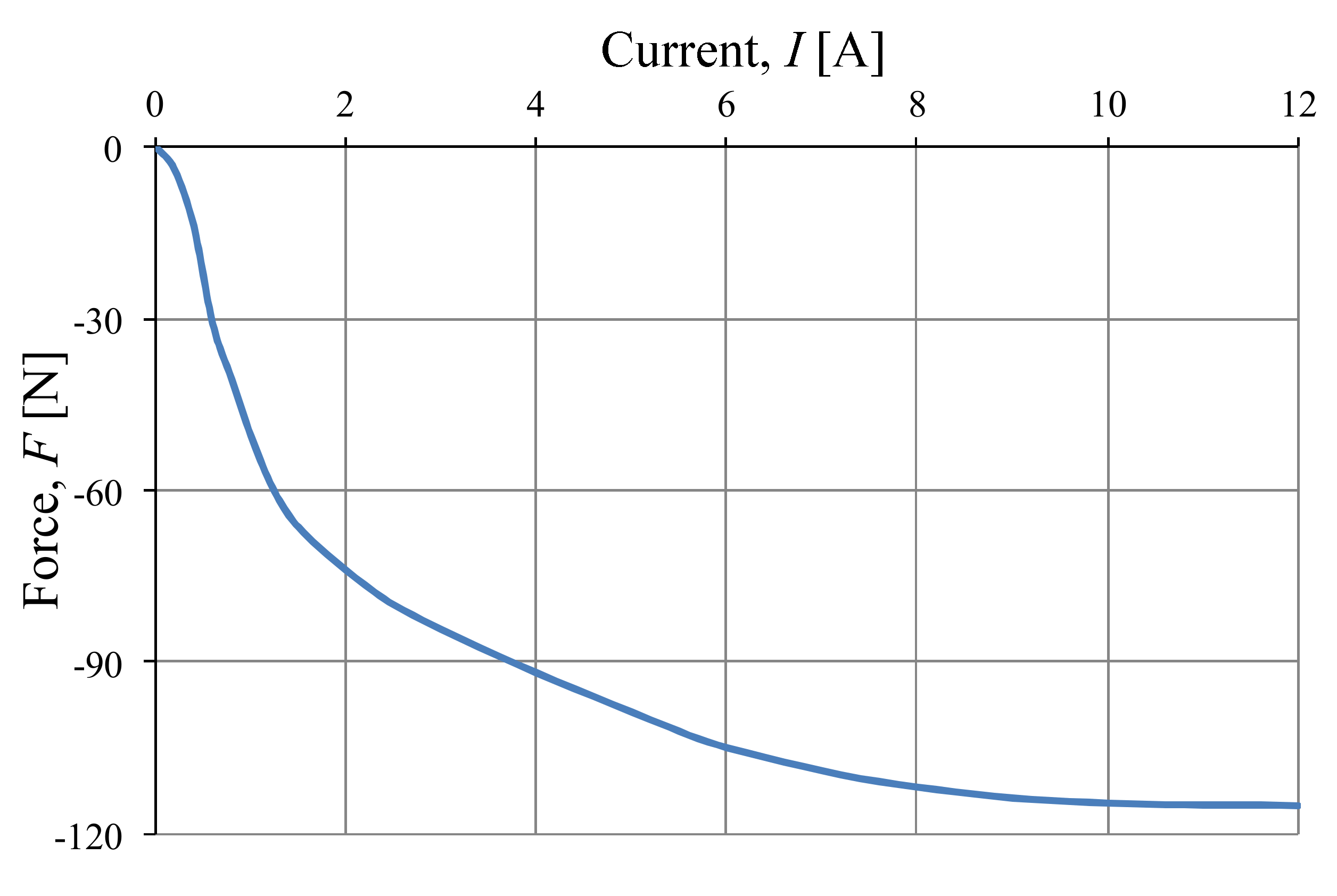
The calculated blocked force of the GMA as a function of supply current is shown in
Figure 10. To determine the blocked force, it was assumed that the Terfenol-D rod was clamped.
The above results show that the proposed numerical model of a giant magnetostrictive actuator can be a useful tool for optimizing the device geometry and material selection.


