Article

Comparative Evaluation of Lifetime of Three-Level Inverters in Grid-Connected Photovoltaic Systems

1
Department of Electronic and IT Media Engineering, Seoul National University of Science and Technology, Seoul 01811, Korea
2
School of Electronics and Electrical Engineering, Dankook University, Yongin-si 16890, Korea
*
Author to whom correspondence should be addressed.
Energies 2020, 13(5), 1227; https://doi.org/10.3390/en13051227
Submission received: 12 February 2020 / Revised: 3 March 2020 / Accepted: 6 March 2020 / Published: 6 March 2020
(This article belongs to the Special Issue Reliability of Power Electronic Systems)

Abstract

:
The cost of the PV energy reduction is still required to increase the penetration level of PV systems in the energy market. The reliability of PV inverters is one of the important aspects to be enhanced in order to reduce the cost of PV energy, since it is closely related to the maintenance cost and the annual energy production. In this paper, the lifetime of NPC and T-type inverters, which are three-level inverter topologies that are widely used for PV systems, are comparatively evaluated with a 30 kW grid-connected PV system. It is performed by focusing on power devices since the power electronic components of both converters are the same except for the power devices. Therefore, this result can represent the comparison of the reliability performance of the NPC and T-type inverters. The power loss and temperature distributions of power devices are analyzed and their efficiencies are compared at different power levels with different switching frequencies. The lifetimes of the reliability-critical power devices in the NPC and T-type inverters are estimated, respectively with a one-year mission profile of the PV system, and the results are compared.

1. Introduction

Solar photovoltaic (PV) energy is one of the promising candidates as an alternative to fossil fuel energy for clean electricity generation. Thanks to continuous cost reduction in PV panels and the balance of systems (BOS) in the last decade, the penetration level of a PV system has increased with rapid growth in renewable energy market [1]. Nevertheless, in order to further increase the penetration level of the PV system, it is still required to improve its competitiveness by reducing the cost of energy by a factor of around three as recommended in [2]. In order to achieve this target, many aspects need to be enhanced. Especially, the reliability of PV systems is one of the important aspects to be considered, since it is closely related not only to the maintenance cost but also to the annual energy production of the PV system [1]. In other words, the reliability improvement of the PV system, which leads to the maintenance cost reduction and increase in annual energy production, is one of the possible solutions to decrease the cost of PV energy.
Based on the field experience, it has been found that the PV inverter takes a great portion of the main causes of failure events and downtime and thus one of the most fragile parts in PV systems [3,4]. Therefore, much research has been performed on the reliability of PV inverters such as reliability tests, condition monitoring, lifetime estimation, and control strategies to analyze and improve the reliability of the PV inverter [5,6,7,8,9,10,11,12,13]. However, as mentioned above, even though the reliability of PV inverters plays an important role to decrease the cost of PV energy, there is still a lack of study on this when the different PV inverter topologies are compared in order to choose the proper topology for the PV system. Typically, the efficiency, total harmonic distortion (THD), and leakage current are considered and emphasized, since these aspects are closely related to the energy production as well as the volume and weight of the PV inverter [14]. In [14,15], the junction temperature profiles of the power devices in different single-phase PV inverter topologies are analyzed and compared. However, it is not enough to show the reliability of single-phase PV inverter topologies.
The three-level inverters are attractive topologies for both high-power and low-power PV systems due to the outstanding efficiency and lower THD compared with the conventional two-level inverter [16,17]. The configurations of PV systems can be divided into an AC module, string, multi-string, and central configurations depending on the rated power of the PV system. Typically, neutral-point clamped (NPC) and T-type three-level inverter topologies are widely used for from a string inverter configuration of small power to a central inverter configuration of high power [18]. Previous research performed the evaluation of three-phase three-level inverter and converter topologies for a motor drive where the efficiency, semiconductor chip area, and harmonic machine losses were taken into account for the comparison factors of the three-level inverter and converter topologies, but the lifetime was not considered [17].
In this paper, the comparative evaluation of the lifetime of three-phase NPC and T-type three-level inverters for the grid-connected PV systems is performed. Except for the power devices, the required power electronic components and applied stress on these components in both inverters are the same. Therefore, it can be expected that the lifetime of other components in both inverters are the same as each other. Therefore, the lifetime of the power device can represent the reliability comparison of the NPC and T-type inverter systems. A 30 kW grid-connected PV system is considered as a case study. In the first section of this paper, configurations of the NPC and T-type inverters are briefly described. Then, the power loss distributions of the power devices in the NPC and T-type inverters are analyzed, and the efficiency of both inverters is compared at the rated power and half of the rated power with different switching frequencies from 3 to 30 kHz. After that, the temperature distributions of the power devices in the NPC and T-type inverters are analyzed. Finally, the lifetimes of the reliability-critical power devices in the NPC and T-type inverters are estimated and compared with a one-year mission profile consisting of the solar irradiation and the ambient temperature in order to compare their reliability.

2. PV NPC and T-Type Inverters

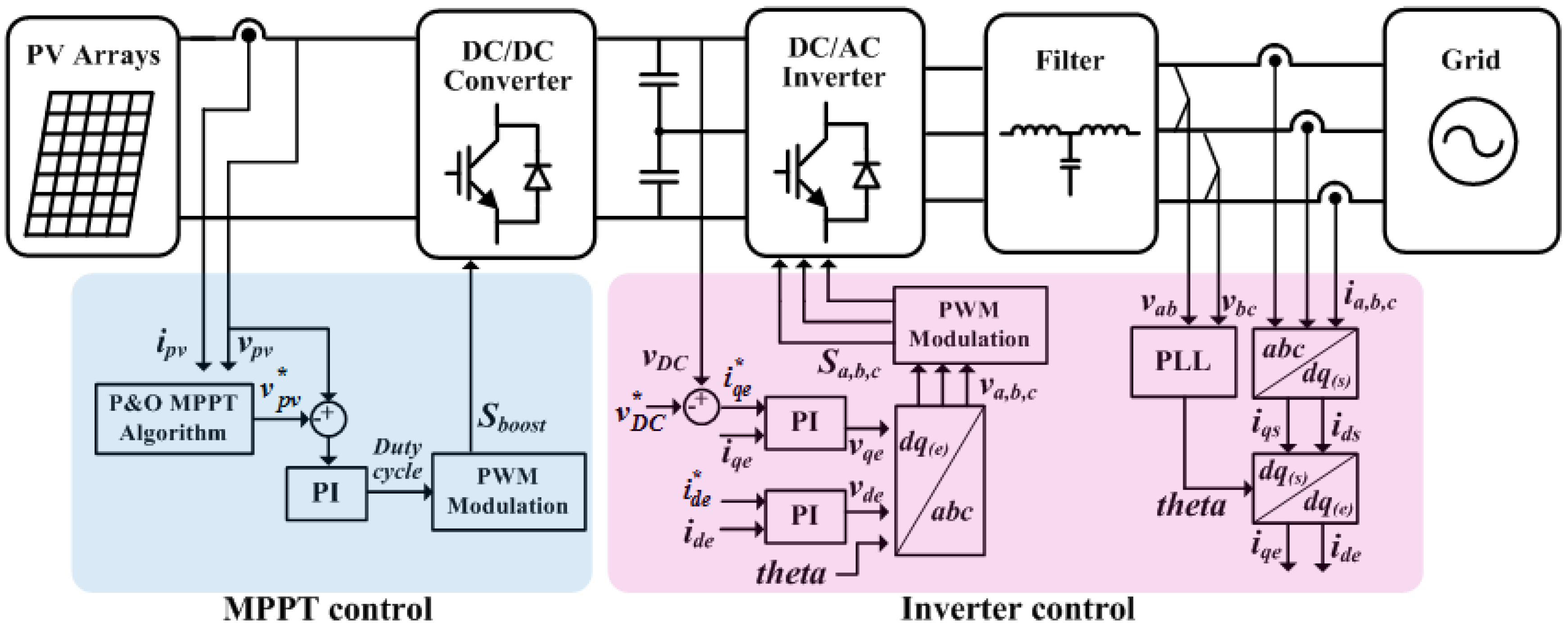
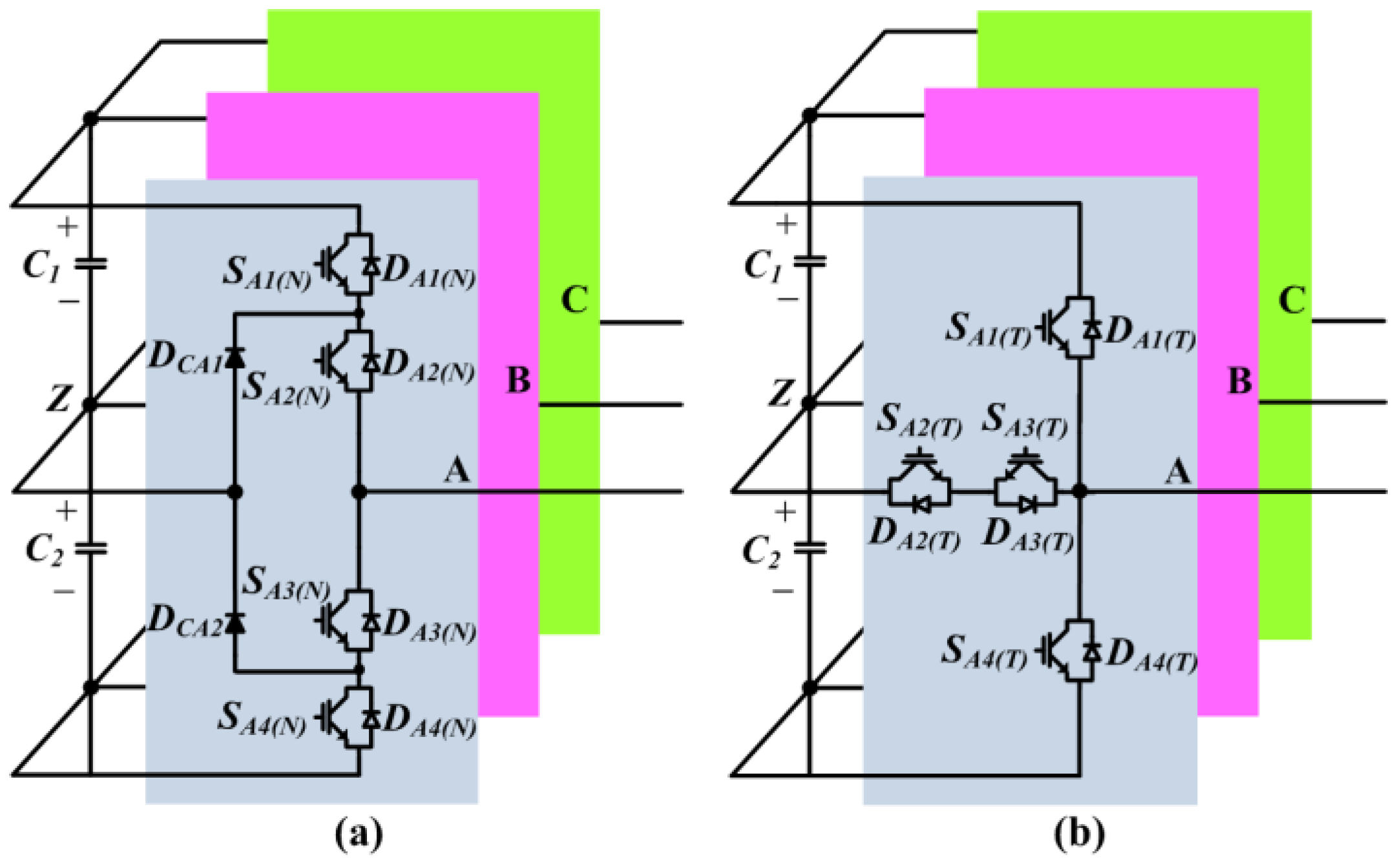
2.1. Description of PV System Configurations of NPC and T-Type Inverters

Figure 1 shows the simplified configuration and control structure of a three-phase grid-connected PV system, where a DC/DC boost converter and a DC/AC inverter called the PV inverter are used as an interface between the PV array and grid. This two-stage configuration is commonly used in PV systems with relatively small rated power from 1 to 30 kW, where the maximum power extraction from the PV arrays is achieved by controlling the DC/DC boost converter.
Depending on the application and power rating, the DC/DC converter is included or not. Typically, the DC/DC boost converter is not employed in the central PV system configuration for high rated power [18].
Figure 2 shows the simplified circuit diagrams of the NPC and T-type inverters. The NPC inverter consists of 4 IGBTs (SX1(N) (X = A,B,C), SX2(N), SX3(N), and SX4(N)), 4 diodes (DX1(N), DX2(N), DX3(N), and DX4(N)) and 2 clamping diodes (DCX1 and DCX2) in each phase as shown in Figure 2a, where all IGBTs have the same voltage and current ratings.
The T-type inverter is composed of 4 IGBTs (SX1(T), SX2(T), SX3(T), and SX4(T)) and 4 diodes (DX1(T), DX2(T), DX3(T), and DX4(T)) in each phase, as illustrated in Figure 2b. In contrast with the NPC inverter, the half-bridge IGBTs (SX1(T) and SX4(T)) have higher voltage and current ratings than the neutral-point IGBTs (SX2(T) and Sx3(T)), and the half-bridge diodes (DX1(T) and DX4(T)) have a higher voltage rating than the neutral-point diodes (DX2(T) and DX3(T)) but have similar or smaller current ratings in a T-type inverter.

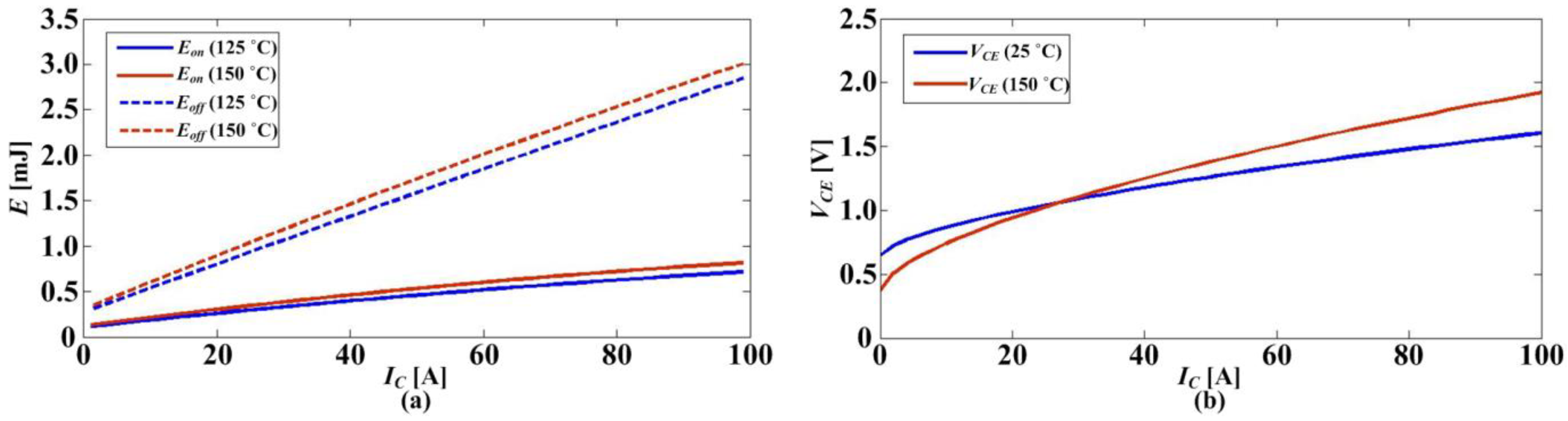
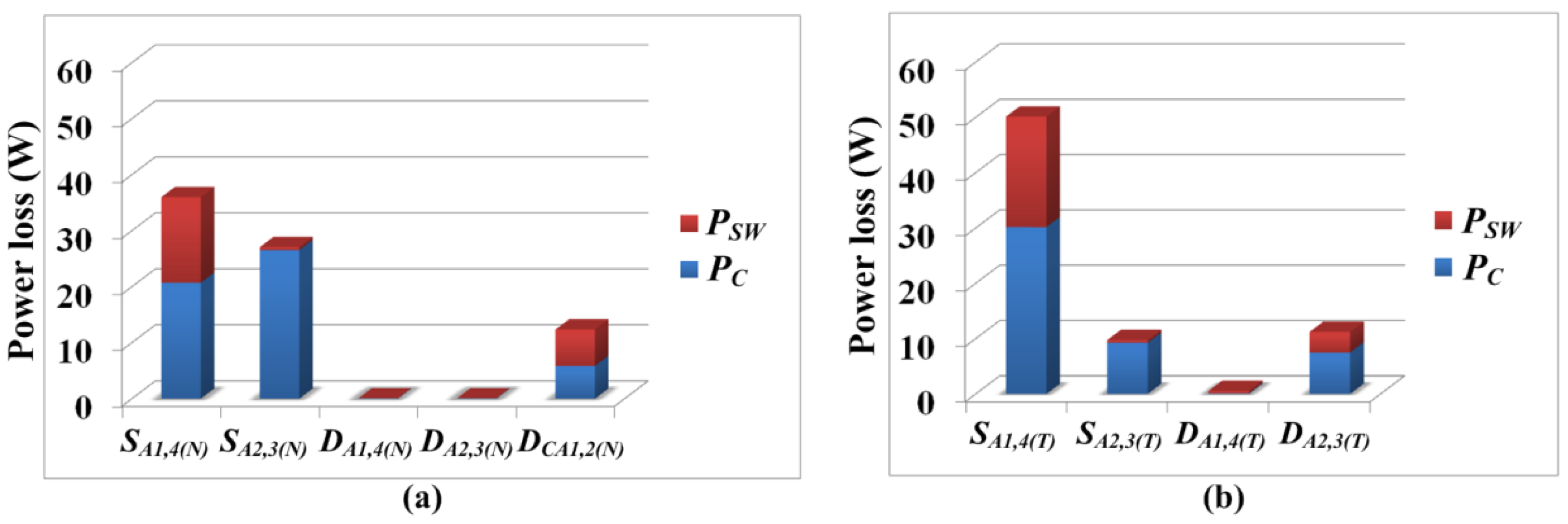
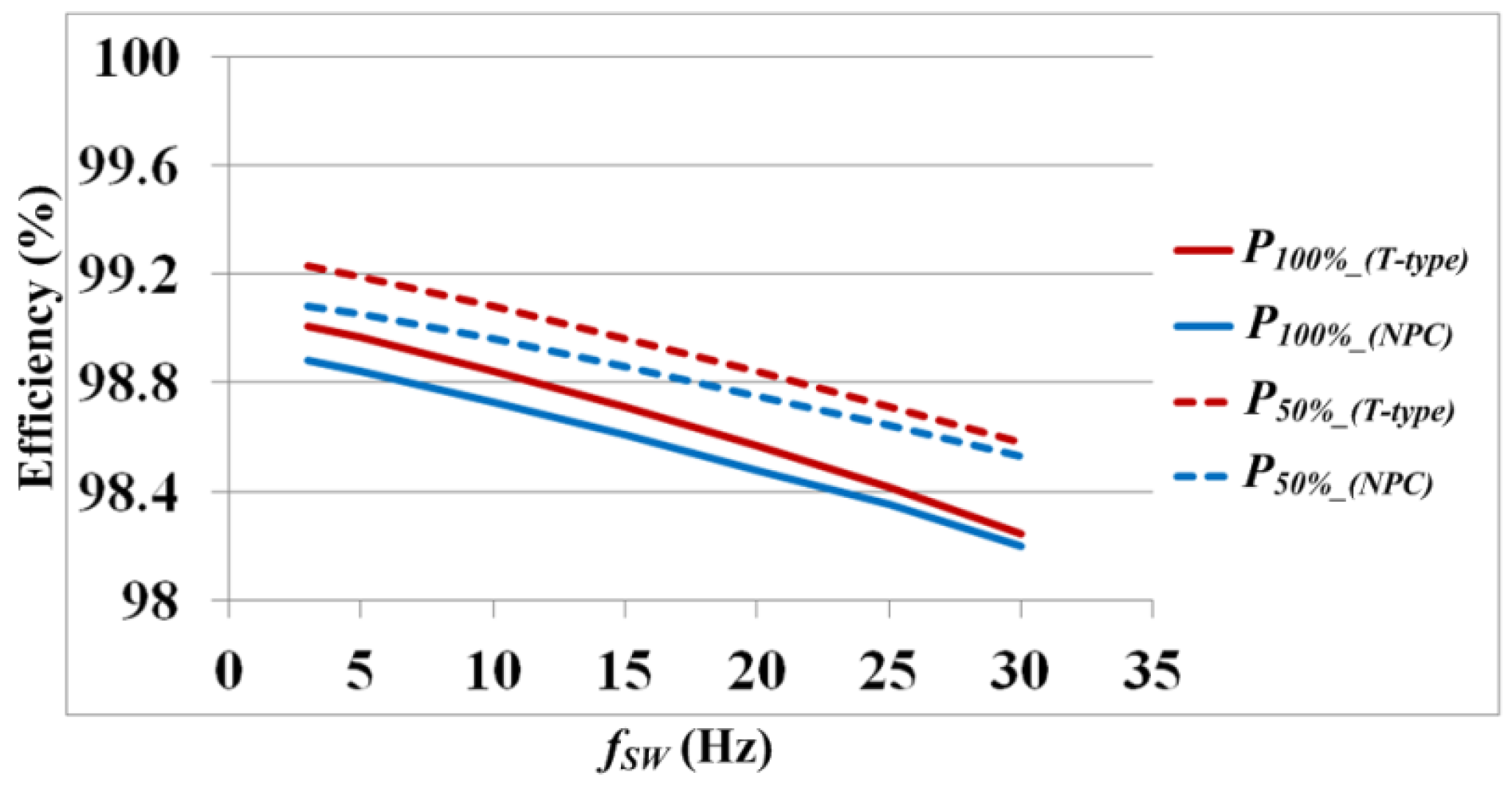
2.2. Efficiencies and Power Loss Distributions of NPC and T-Type Inverters

The efficiency is one of the important performance factors of PV inverters, since it is related to the energy production and the cost of PV inverters. In this section, efficiencies of NPC and T-type inverters in 30 kW PV systems are evaluated at the rated power and half of the rated power under the different switching frequencies. Since the typical switching frequency range of the PV inverter with IGBT is not above 30 kHz, the range of fsw from 3 to 30 kHz is considered for the efficiency comparison. The related parameters of the PV system are listed in Table 1. It is worthwhile to mention that the conventional space vector modulation (SVM) is applied to both topologies, and the power losses of semiconductor devices are only considered for the comparison of the efficiency. In respect to the Safe Operating Area of the power devices, the maximum junction temperature of the power device is one of the important factors. Typically, the rating of the power device module and cooling system capacity are chosen so that the junction temperature under the rated power of an inverter is 70%–80% of the maximum junction temperature [19]. For that, the proper IGBT modules F3L75R07W2E3_B11 and F3L75R12W1H3_B11 from the same manufacturer are selected for NPC and T-type inverters, respectively. The maximum junction temperature allowed for the power devices in both IGBT modules is 175 °C, and they have almost the same price.
The heat-sink to ambient thermal resistance Rth(h−a) is set to 0.108 K/W, so that the maximum junction temperature of the IGBT in the T-type inverter is 120 °C at the rated power when the switching frequency is 30 kHz and the ambient temperature is 30 °C. The same R(h−a) is applied to the NPC inverter.
The power loss of the power device consists of the conduction loss and switching loss. The average conduction loss (PC) in one switching cycle is represented as
P C = V C E I C D
where IC is the collector current, D is the duty cycle, and VCE is the collector–emitter voltage.
The switching loss of the IGBT is calculated as
P S W = f S W E S W
where fSW is the switching frequency and ESW is the switching energy of the power device, which is the summation of turn-on and turn-off energies.
Figure 3 shows the Esw and VCE_ON of the IGBT in the NPC inverter. It can be seen that the values are influenced by the junction temperature. Therefore, the junction temperature should be considered for the power loss calculation. The simple foster thermal model is used to estimate the junction temperature. A more detailed description of the thermal model is given in the next section.
Figure 4a,b shows the power loss distributions of phase A of the NPC and T-type inverters, respectively at the rated power with the switching frequency (fsw) of 20 kHz.
The medium range of switching frequency from 12 to 25 kHz is often used to reduce the size of passive components. Further, for the residential PV system, the fsw above 18 kHz is typically chosen to avoid acoustic noise. Due to those reasons, 20 kHz of fsw is selected for the case study.
In the case of the NPC inverter, the outer IGBTs (SA1(N), SA4(N)) and the inner IGBTs (SA2(N), SA3(N)) have the different power losses even though the same IGBTs are used. The conduction loss is the main power loss of the inner IGBTs, since each of the inner IGBTs is clamped for half of the fundamental period complementary, and the current flows through the clamped inner IGBT. On the other hand, in the case of the outer IGBTs, not only the conduction loss but also the switching loss has a large portion of the power loss, since they are switched on and off with high current. As the switching frequency increases, the power loss difference between the outer and inner IGBTs is getting bigger. The power losses of clamping diodes also take a big portion of the total power loss. The power loss of the SA1(T) and SA1(T) are dominant in the T-type inverter. There are several reasons. First, the SA1(T) and SA4(T) have the higher rated power than SA2(T) and SA3(T). Therefore, it has higher power loss. Second, the turn-on periods of SA1(T) and SA4(T) are longer than those of SA2(T) and SA3(T) since typically, the modulation index of the PV inverter is high and thus SA1(T) and SA4(T) have higher conduction losses. Finally, in typical SVM, SA2(T) and SA3(T) are clamped for half of the fundamental period alternately, whereas SA1(T) and SA4(T) are turned on and off with high current. Therefore, they have high switching loss.
The efficiencies of T-type and NPC inverters at the rated power (P100%) and half of the rated power (P50%) with different switching frequencies are shown in Figure 5. As the switching frequency increases, the efficiencies of both inverters decrease due to the increased switching losses. The main benefit of the T-type inverter compared with the NPC inverter comes from the reduced conduction loss, since there are no two IGBTs in series. However, the higher rated IGBT used for the half-bridge in the T-type inverter has higher switching loss than that of the IGBT used for the NPC inverter. Therefore, the efficiency of the T-type inverter is outstanding, and its superiority in the efficiency is clearly seen in the relatively low switching frequency region. As the switching frequency increases, the benefit of the T-type inverter in the efficiency is reduced. The efficiency at P50% has the same trend but better efficiency with that of at P100%. This may be due to the lower junction temperatures of the power devices at P50% than that of at P100%, which leads to the lower power loss, as shown in Figure 3, but it could be different depending on the semiconductor and packaging technologies.
From the results of the efficiency comparison, it can be clearly seen that the T-type inverter is superior to the NPC inverter in terms of efficiency in the considered switching frequency range with these target IGBT modules.

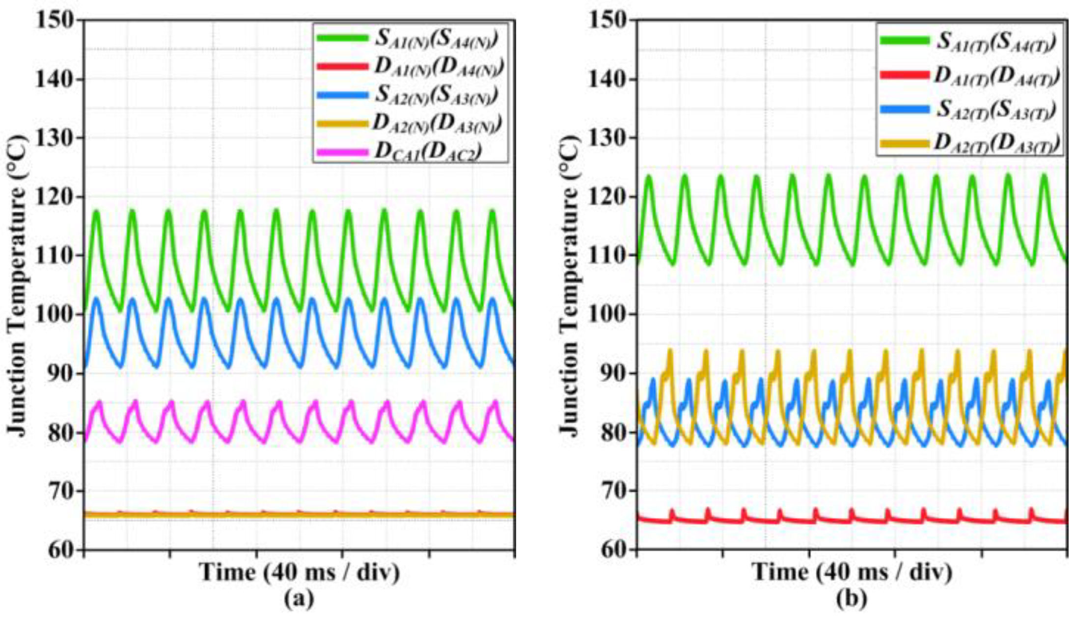
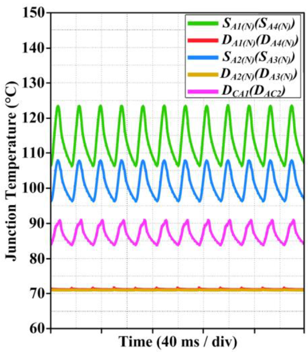
2.3. Temperature Distributions of NPC and T-Type Inverters

It shows that the power losses of IGBTs are dominant and also show uneven loss distribution among the power devices for both topologies. It may lead to uneven junction temperature distributions among the power devices. The temperature distributions of the power devices in NPC and T-type inverters are analyzed to investigate the most reliability-critical devices in terms of temperature stress in both inverters, since typically the lifetimes of the both PV inverters are dependent on them.
The temperature distributions under the steady-state condition are considered at P100% with fsw of 20 kHz for the case study. Further, the heat sink to ambient thermal resistance Rth(h−a) is set to 0.225 K/W so that the maximum junction temperature of the power device in the T-type inverter is about 70% of the maximum allowed junction temperature at the rated power when the fsw is 20 kHz and the ambient temperature is 30 °C. Furthermore, the thermal capacitance of the heat sink to ambient is neglected since the steady-state condition is considered.
The power device thermal network consists of thermal impedances of junction to case (Zth(j−c)), case to heat sink (Zth(c−h)), and heat sink to ambient (Zth(h−a)). The thermal characteristic of power devices from the junction to case Zth(j−c) or from the junction to heat sink Zth(j−h) can be represented by a Foster model as
Z t h ( j c ) ( t ) = i = 1 n R i ( 1 e t / τ i )
where τ = RC and i means the different layers of a module for the Foster model.
Figure 6 shows the thermal equivalent block diagram of a part of an NPC IGBT module with a Foster model and the related parameters obtained from the datasheet are listed in Table 2.
Finally, the junction temperature of the IGBT (or diode) is obtained from the thermal impedances and the power losses of IGBT and IGBT module as
T j ( I G B T ) ( t ) = P l o s s ( I G B T ) ( t ) Z t h ( j h ) ( t ) + P l o s s ( I G B T _ M o d u l e ) ( t ) Z t h ( h a ) ( t ) + T a
where Tj(IGBT) = the junction temperature of the IGBT, Ploss(IGBT) = the power loss of the IGBT, Zth(j−h) = the thermal impedance of junction to heat sink, Ploss(IGBT_Module) = the power loss of the IGBT module, Zth(h−a) = the thermal impedance of heat sink to ambient, and Ta = ambient temperature. It is worth mentioning that in steady-state temperature analysis, Zth(h−a) is simply considered as a constant thermal resistance Rth(h−a) due to the large thermal capacitance of heat sink to ambient, and the average value of Ploss(IGBT_Module) for the fundamental period is applied.
Figure 7a shows the junction temperatures (Tj) of the power devices in the NPC inverter. There is a large temperature difference between the inner and outer IGBTs due to the different loss distributions, and the outer IGBTs have the highest Tj of 117.5 °C, which is 15 °C higher than that of the inner IGBTs. It means that the outer IGBTs are the most reliability-critical device, and they play the key role in the lifetime of the NPC inverter.
The power devices that have the highest Tj in the T-type inverter are the half-bridge IGBTs, SA1(T) and SA4(T), as shown in Figure 7b. The Tj of SA1(T) and SA4(T) are about 124 °C, and it is higher than that of the neutral-point IGBTs, which is about 29 °C.
From this result, it is found that the SA1(T) and SA4(T) are the most reliability-critical devices in the T-type inverter. Furthermore, it can be expected that the chip sizes of the inner IGBTs in the NPC inverter and the neutral-point IGBTs and diodes in the T-type inverter can be reduced in the PV system since their Tj are relatively low compared with the IGBTs having the highest temperatures in both topologies, and it may lead to the reduction of the costs of power modules.
When the same Rth(h−a) of 0.225 K/W is applied to both topologies, the maximum Tj of the IGBT in the T-type inverter is greater than that of the IGBT in the NPC inverter by about 6.5 °C. It means that for the same power rating, the Rth(h−a) of the NPC inverter can increase so that the maximum Tj of the IGBT is about 124 °C. In other words, the heat-sink size or cooling system capacity for the NPC inverter can be reduced, which leads to the cost reduction of the PV system.
Figure 8 shows the junction temperature of the power devices in the NPC inverter when Rth(h−a) increases by 0.03 K/W from 0.225 to 0.255 K/W. Then, Tj of SA1(N) and SA4(N) increase from 117.5 to about 124 °C, which is the same with Tj of SA1(T) and SA4(T).

3. Lifetime Evaluation of NPC and T-Type Inverters

The lifetime of the reliability-critical power devices in the NPC and T-type inverters are evaluated under a one-year mission profile of the PV system. Except for the power devices, the other power electronic components required for both inverters are the same. Therefore, the lifetimes of the power devices could be a benchmark for the reliability comparison of the NPC and T-type inverter systems. From the previous analysis, it has been found that the outer IGBTs (SX(X = A,B,C)1(N), SX4(N)) in the NPC inverter and the half-bridge IGBTs (SX1(T), SX4(T)) in the T-type inverter are the most reliability-critical component under the given PV inverter specification listed in Table 1 with an fSW of 20 kHz.
It is worth noticing that the temperature stress is considered when the lifetime evaluation of the power devices is carried out, since it is the main cause of the wear-out failure of standard power modules [20]. Furthermore, in this target system, power devices are not the discrete devices but rather the power module. It means that the lifetime of the power module is mainly dependent on the most stressful device, as analyzed in [21]. Therefore, the lifetime evaluation should be focused on them.
Figure 9 shows the lifetime evaluation procedure of the power devices in PV inverters with the mission profile. The loss profile of the power device in a PV inverter needs to be obtained first from PV system information such as the power device characteristics, PV inverter characteristics, and mission profiles of a PV system. Then, the power loss profile is translated into the thermal loading of the power device. After that, the required stress factors such as junction temperature swing (∆Tj) and mean junction temperatures (Tjm) used in a lifetime model are extracted from the thermal loading profile by using a Rainflow counting method. Finally, the lifetime of the power device is estimated based on a Miner’s rule by putting the accounted temperature stress factors into a lifetime model.

3.1. Mission Profile of PV System

The solar irradiation and the ambient temperature are considered as the mission profile of the PV system, since they are the main factors that affect the PV power production. The mission profile recorded from Spain for almost 1 year (351 days) with the sampling rate of 1 minute/data shown in Figure 10 is used for the lifetime evaluation. It can be seen that the ambient temperature is varied from about −5 to 30 °C, and the solar irradiation is constantly high throughout the whole year.

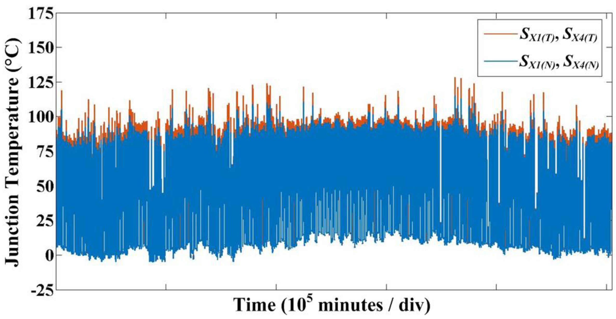
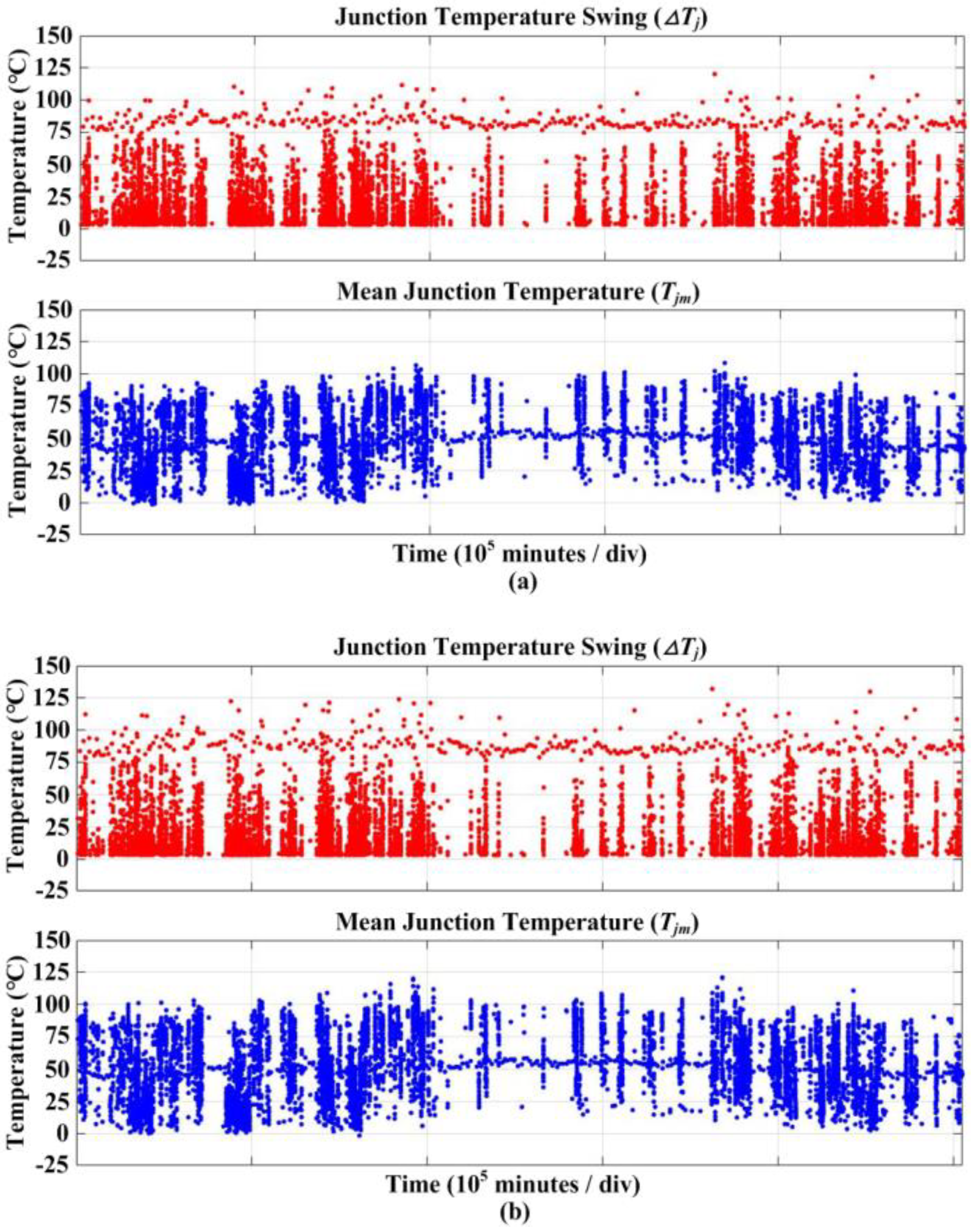
3.2. Junction Temperature Profile from Mission Profile

The generated power by PV arrays is determined by these two values based on the panel characteristic model and then the PV power profile corresponding to the mission profile is obtained, where the MPPT efficiency is assumed as 99% and the generated PV power is limited to 120% of the rated power of the PV inverter so that the junction temperature of the power devices is within its Safe Operating Area.
Based on the input power of the PV inverter, the power losses of the target devices, which are outer IGBTs and half-bridge IGBTs in the NPC and T-type inverters, respectively are determined. Then, the corresponded junction temperatures of the IGBTs are acquired based on the Foster thermal model of the IGBTs, as previously explained in the sections C and D of §III. After that, the junction temperature profiles of the IGBTs are obtained by using a look-up table, which is generated based on the information about the junction temperatures under the different input power levels and the ambient temperatures, where the junction temperature of the device is determined when the input power of the PV inverter generated by the PV arrays and the ambient temperature is given. The look-up table-based analysis is helpful to deal with a lot of the data of the one-year mission profile. Furthermore, since the data are recorded with a sampling rate of 1 minute/data, the real-time simulation, which takes a long time to have the junction temperature profile, may not be required.
Figure 11 shows the junction temperature profiles of the outer IGBTs and half-bridge IGBTs of the NPC and T-type inverters, respectively. It is observed that SX1(T) and SX4(T) in the T-type inverter have relatively higher junction temperatures than SX1(N) and SX4(N) in the NPC inverter during the whole of the year.

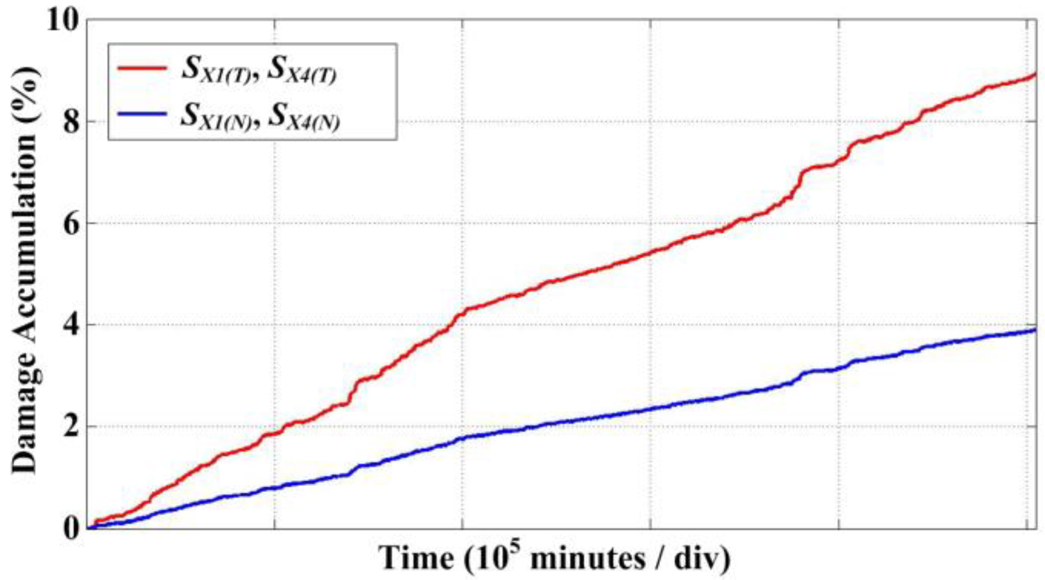
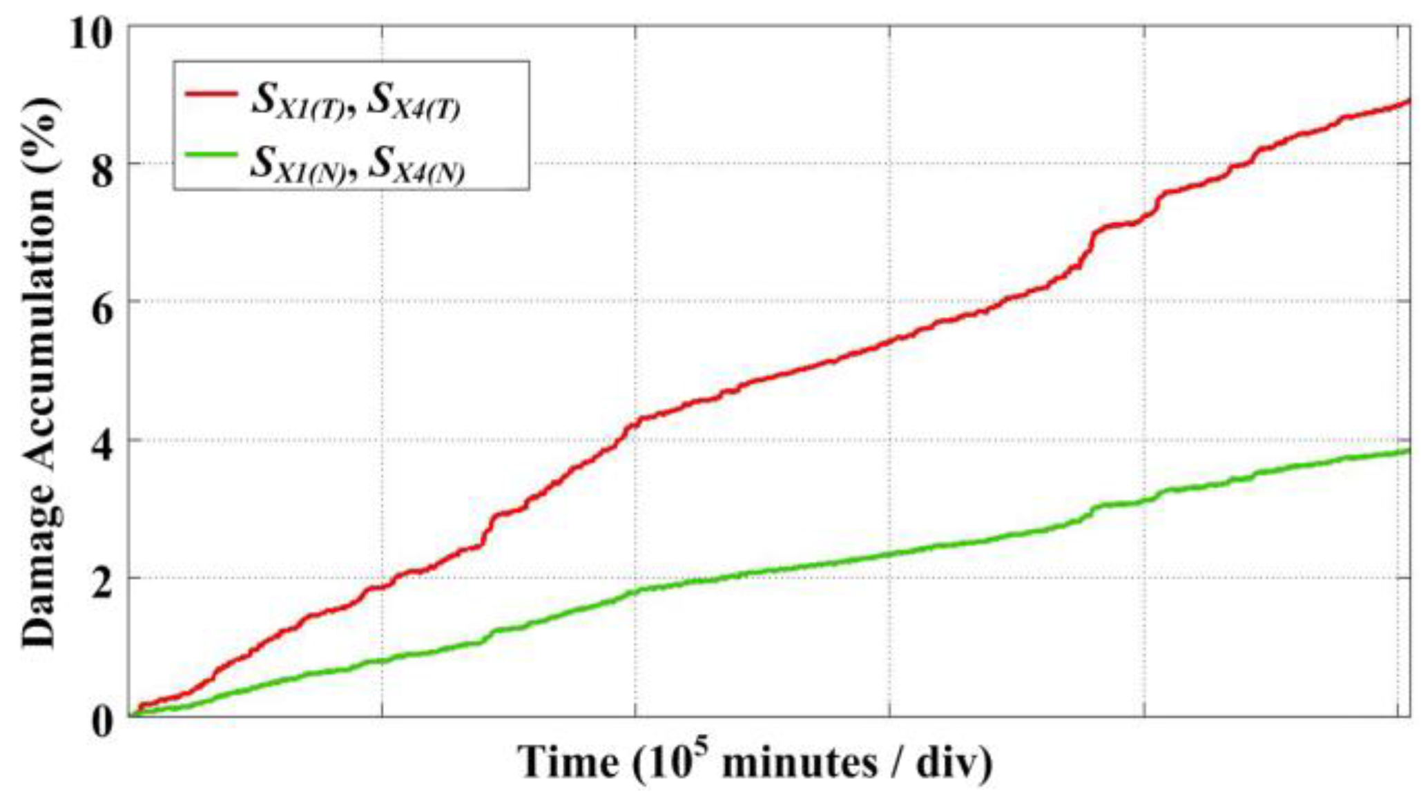
3.3. Lifetime Evaluation

The temperature stress factors should be extracted from the temperature profile of the power device in order to evaluate the lifetime of the power device with a lifetime model in respect to temperature stress. The junction temperature swing (∆Tj), mean junction temperature (Tjm), and junction temperature swing on-time period (ton) are considered, and they are extracted by using a Rainflow counting method [22].
Tj and Tjm extracted from the junction temperature profiles of the outer IGBTs and half-bridge IGBTs of the NPC and T-type inverters are shown in Figure 12a,b, respectively.
It is shown that the ∆Tj and Tjm extracted from the junction temperature profiles of the half-bridge IGBTs of the T-type inverter are higher than those of the outer IGBTs of the NPC inverter. Therefore, it can be expected that the T-type inverter has a shorter lifetime than the NPC inverter.
The extracted stress factors are put into the lifetime model in order to obtain the number of cycles to failure by the given stress factors of ∆Tj, Tjm, and ton. Since the lifetime models of the target IGBT modules in this study are not available, the lifetime model presented in [23] is used. Therefore, the estimated lifetime results of the IGBTs should be considered only for the purpose of the lifetime comparison between the NPC and T-type inverters.
Finally, the Damage Accumulation (DA) of the IGBT is calculated based on the Miner’s rule, which is one of the most widely used cumulative damage models, and it is defined as
D A = i = 1 k n i N i
where ni is the number of cycles accumulated at a certain temperature stress Si and Ni is the number of cycles to failure at the temperature stress Si.
Consequently, DA can be used to indicate how much damage of the IGBT is accumulated or how much life of the IGBT is consumed during the mission profile and the time at which DA reaches 1% or 100% is considered as the lifetime of the IGBT.
Figure 13a shows the DA of the SX1(N) and SX4(N) of the NPC inverter when the PV inverter is operated with the given mission profile. The DA during the given mission profile of 351 days is 0.039 (or 3.9%), and thus, it is expected that the lifetime of the outer IGBT of the NPC inverter is about 25 years. In the case of the T-type inverter, the lifetime of the half-bridge IGBTs is expected to be 11 years, since the DA of SX1(T) and SX4(T) is 0.089 (or 8.9%), as shown in Figure 13b. It can be seen that the NPC inverter has about 2.3 times a longer lifetime than the T-type inverter under the same mission profile of the PV system.
One of the main reasons that they have different lifetimes is due to the different thermal loadings. As shown in Figure 10, SX1(T) and SX4(T) of the T-type inverter have higher ∆Tj and Tjm than SX1(N) and SX4(N) of the NPC inverter throughout the whole year, which thus leads to the shorter lifetime. The voltage rating of the IGBT is also related to its lifetime. The voltage rating of the IGBT in the NPC inverter is 650 V. On the other hand, the IGBTs that have a 1200 V voltage rating are used for the half-bridge legs of the T-type inverter. The voltage rating of the IGBT is related to the IGBT chip thickness. The higher voltage rating of the IGBT means that the thicker thickness of the IGBT and the chip thickness affects the lifetime, since as the chip thickness increases, the higher thermomechanical stress is applied, and thus it leads to the shorter lifetime as explained in [23,24]. This effect is taken into account in the considered lifetime model as voltage class. This is another reason that the T-type inverter has a shorter lifetime than the NPC inverter.
The lifetime of T-type inverter without changing in the inverter output performance can be improved by reducing Rth(h−a), which can be achieved by increasing the size of the heat sink or by improving the cooling system capacity. That leads to the decrease in the mean junction temperature and thus the lifetime increases, as shown in Figure 14.
Figure 14 shows the DA of the SX1(T) and SX4(T) of the T-type inverter when Rth(h−a) is reduced. By reducing Rth(h−a), Tjm of SX1(T), and SX4(T) of the T-type inverter is reduced, and therefore the DA during the given mission profile decreases. It can be seen that when Rth(h−a) decreases by 0.145 K/W, DA is about 0.0384 (or 3.84%) and thus the expected lifetime is about 25 years. It is almost the same with the lifetime of the NPC inverter. Consequently, from the above analysis, it can be concluded that the lifetime of the NPC inverter is higher than that of the T-type inverter and thus has superiority over the reliability of the T-type inverter in this case study with a specific mission profile. Further, the T-type inverter requires higher cooling capacity than the NPC inverter in order to have the same lifetime.

4. Conclusions

In this paper, the reliability of the most widely used three-level inverter topologies for PV systems, which are NPC and T-type inverters, has been comparatively evaluated by focusing on the power devices with a 30 kW grid-connected PV system. It has been shown that the T-type inverter has the outstanding efficiency compared with NPC inverter in the considered switching frequency ranges from 3 to 30 kHz. Therefore, the T-type inverter is able to produce more energy from the PV arrays at the same operating condition. However, even though the T-type inverter has better efficiency, the NPC inverter has better thermal behavior. Both inverters have the non-uniform power loss distributions and thus have different junction temperatures among devices. In the case of the T-type inverter, the IGBTs located at half-bridge legs have the highest junction temperatures of 124 °C and the outer IGBTs of the NPC inverter have the junction temperature of 117.5 °C, which is the highest junction temperature in the NPC inverter when they have the same Rth(h−a) of 0.225 K/W. The Rth(h−a) of the NPC inverter can increase by 0.255 K/W so that it has the same maximum junction temperature of 124 °C with the T-type inverter. Consequently, the smaller heat-sink size or cooling system capacity can be used for the NPC inverter compared with T-type inverter. Finally, the lifetime of the reliability-critical devices in the NPC and T-type inverters has been estimated by considering almost one-year mission profile of the PV system, and the result has been compared.
The lifetimes of the power devices in the NPC inverter and T-type inverter are 25 and 11 years, respectively. It can be seen that the NPC inverter has 2.3 times longer lifetime than that of the T-type inverter. Thus, when a typical lifetime warranty of 25 years provided by the manufacturers are considered as presented in [17], it is expected that the cost of the PV energy with the T-type inverter is higher than that of the NPC inverter due to the maintenance cost and a cutback in the total energy production due to the downtime of the PV system. The T-type inverter needs an Rth(h−a) of 0.145 K/W for the same lifetime of 25 years with the NPC inverter, and therefore requires a higher capital cost than the NPC inverter.
It is worthwhile mentioning that it is not always the case that it is proper to choose an NPC inverter to reduce the cost of energy due to better reliability, since the result could be different depending on the PV inverter parameters such as the switching frequency, modulation index, and power rating. Therefore, this result should be used for emphasizing the importance of the reliability of PV inverters on the cost of PV energy.

Author Contributions

Conceptualization and writing—original draft, methodology and validation, formal analysis, U.-M.C.; supervision and guidance—review and editing, J.-S.L. All authors have read and agreed to the published version of the manuscript.

Funding

This study was supported by the Research Program funded by the Seoul National University of Science and Technology.

Conflicts of Interest

The authors declare no conflict of interest.

References

  1. REN21, Paris, France, Renewables 2018: Global Status Report (GRS). 2018. Available online: http://www.ren21.net/ (accessed on 26 June 2018).
  2. Woodhouse, M.; Feldman, R.D.; Fu, R.; Horowitz, K.; Chung, D.; Jordan, D.; Kurtz, S. On the Path to SunShot: The Role of Advancements in Solar Photovoltaic Efficiency, Reliability, and Costs; NREL/TP-6A20-65872; National Renewable Energy Laboratory: Golden, CO, USA, 2016.
  3. Moore, L.M.; Post, H.N. Five years of operating experience at a large, utility-scale photovoltaic generating plant. Prog. Photovolt. Res. Appl. 2008, 16, 249–259. [Google Scholar] [CrossRef]
  4. Solar Bankability. Technical Risks in PV Projects: Report on Technical Risks in PV Project Development and PV Plant Operation; European Union: Brussels, Belgium, 2016. [Google Scholar]
  5. Choi, U.M.; Blaabjerg, F.; Jorgensen, S. Power Cycling Test Methods for Reliability Assessment of Power Device Modules in Respect to Temperature Stress. IEEE Tran. Power Electron. 2018, 33, 2531–2551. [Google Scholar] [CrossRef] [Green Version]
  6. Dbeiss, M.; Avenas, Y.; Zara, H.; Dupont, L.; Al Shakarchi, F. A Method for Accelerated Aging Tests of Power Modules for Photovoltaic Inverters Considering the Inverter Mission Profiles. IEEE Trans. Power Electron. 2019, 34, 12226–12234. [Google Scholar] [CrossRef]
  7. Sangwongwanich, A.; Shen, Y.; Chub, A.; Liivik, E.; Vinnikov, D.; Wang, H.; Blaabjerg, F. Mission Profile-based Accelerated Testing of DC-link Capacitors in Photovoltaic Inverters. In Proceedings of the 2019 IEEE APEC, Anaheim, CA, USA, 17–21 March 2019. [Google Scholar]
  8. Choi, U.M.; Blaabjerg, F. Separation of Wear-Out Failure Modes of IGBT Modules in Grid-Connected Inverter Systems. IEEE Trans. Power Electron. 2018, 33, 6217–6223. [Google Scholar] [CrossRef]
  9. Agarwal, N.; Ahmad, M.W.; Anand, S. Quasi-Online Technique for Health Monitoring of Capacitor in Single-Phase Solar Inverter. IEEE Trans. Power Electron. 2018, 33, 5283–5291. [Google Scholar] [CrossRef]
  10. Huang, H.; Mawby, P.A. A Lifetime Estimation Technique for Voltage Source Inverters. IEEE Trans. Power Electron. 2013, 28, 4113–4119. [Google Scholar] [CrossRef]
  11. Yang, Y.; Wang, H.; Blaabjerg, F.; Kerekes, T. A Hybrid Power Control Concept for PV Inverters With Reduced Thermal Loading. IEEE Trans. Power Electron. 2014, 29, 6271–6275. [Google Scholar] [CrossRef] [Green Version]
  12. Aly, M.; Ahmed, E.M.; Shoyama, M. Modulation Method for Improving Reliability of Multilevel T-type Inverter in PV Systems. IEEE J. Emerg. Sel. Top. Power Electron. 2019. [Google Scholar] [CrossRef]
  13. Khan, M.N.H.; Forouzesh, M.; Siwakoti, Y.P.; Li, L.; Kerekes, T.; Blaabjerg, F. Transformerless Inverter Topologies for Single-Phase Photovoltaic Systems: A Comparative Review. IEEE J. Emerg. Sel. Top. Power Electron. 2020, 8, 805–835. [Google Scholar] [CrossRef]
  14. Yang, Y.; Wang, H.; Blaabjerg, F.; Ma, K. Mission Profile based Multi-Disciplinary Analysis of Power Modules in Single-Phase Transformerless Photovoltaic Inverters. In Proceedings of the 15th European Conference on Power Electronics and Applications (EPE), Lille, France, 2–6 September 2013. [Google Scholar]
  15. Schweizer, M.; Kolar, J.W. Design and Implementation of a Highly Efficient Three-Level T-Type Converter for Low-Voltage Applications. IEEE Trans. Power Electron. 2013, 28, 899–907. [Google Scholar] [CrossRef]
  16. Choi, U.M.; Ma, K.; Blaabjerg, F. Validation of Lifetime Prediction of IGBT Modules Based on Linear Damage Accumulation by Means of Superimposed Power Cycling Tests. IEEE Trans. Ind. Electron. 2018, 65, 3520–3529. [Google Scholar] [CrossRef]
  17. Schweizer, M.; Friedli, T.; Kolar, J.W. Comparative Evaluation of Advanced Three-Phase Three-Level Inverter/Converter Topologies Against Two-Level Systems. IEEE Trans. Ind. Electron. 2013, 60, 5515–5527. [Google Scholar] [CrossRef]
  18. Kouro, S.; Leon, J.I.; Vinnikov, D.; Franquelo, L.G. Grid-Connected Photovoltaic Systems: An Overview of Recent Research and Emerging PV Converter Technology. IEEE Ind. Electron. Mag. 2015, 9, 47–61. [Google Scholar] [CrossRef]
  19. Mitsubishi Electric, Power Module Reliability. pp. 1–13. Available online: www.mitsubishielectric.com/semiconductors/products/pdf/reliability/0512_e.pdf (accessed on 25 December 2019).
  20. Choi, U.M.; Blaabjerg, F.; Lee, K.B. Study and Handling Methods of Power IGBT Module Failures in Power Electronic Converter Systems. IEEE Trans. Power Electron. 2015, 30, 2517–2533. [Google Scholar] [CrossRef]
  21. Choi, U.M.; Vernica, I.; Blaabjerg, F. Effect of Asymmetric Layout of IGBT Modules on Reliability of Motor Drive Inverters. IEEE Trans. Power Electron. 2019, 34, 1765–1772. [Google Scholar] [CrossRef] [Green Version]
  22. Musallam, M.; Johnson, C.M. An Efficient Implementation of the Rainflow Counting Algorithm for Life Consumption Estimation. IEEE Trans. Reliab. 2012, 61, 978–986. [Google Scholar] [CrossRef]
  23. Bayerer, R.; Herrmann, T.; Licht, T.; Lutz, J.; Feller, M. Model for Power Cycling lifetime of IGBT Modules—Various factors influencing lifetime. In Proceedings of the 5th International Conference on Integrated Power Electronics Systems, Nuremberg, Germany, 11–13 March 2008. [Google Scholar]
  24. Scheuermann, U.; Schmidt, R. A New Lifetime Model for Advanced Power Modules with Sintered Chips and Optimized Al Wire Bonds. In Proceedings of the International Exhibition and Conference for Power Electronics, Intelligent Motion, Renewable Energy and Energy Management, Nuremberg, Germany, 1–10 May 2013. [Google Scholar]
Figure 1. Configuration and control structure of two-stage three-phase PV system (PI—proportional integral, PLL—phase-locked loop, PWM—pulse width modulation, S—switching function).
Energies 13 01227 g001
Figure 2. Simplified circuit diagrams of three-level inverters: (a) neutral-point clamped (NPC) inverter; (b) T-type inverter.
Energies 13 01227 g002
Figure 3. The turn-on and turn-off energies (Eon and Eoff) and forward voltage drop (VCE) of the IGBT in the NPC inverter under different junction temperatures: (a) Eon and Eoff; (b) VCE.
Energies 13 01227 g003
Figure 4. The power losses distributions: (a) NPC inverter; (b) T-type inverter at the rated power with fsw of 20 kHz.
Energies 13 01227 g004
Figure 5. Efficiencies of T-type and NPC inverters with different switching frequencies.
Energies 13 01227 g005
Figure 6. The thermal equivalent block diagram of a part of the IGBT module with a Foster model.
Energies 13 01227 g006
Figure 7. Junction temperatures of the power devices at the rated power when fsw = 20 kHz and Rth(h−a) = 0.225 K/W: (a) NPC inverter; (b) T-type inverter.
Energies 13 01227 g007
Figure 8. Junction temperatures of the power devices in the NPC inverter at the rated power when fsw = 20 kHz and Rth(h−a) = 0.255 K/W.
Energies 13 01227 g008
Figure 9. Lifetime evaluation procedure of the power devices in the PV inverter.
Energies 13 01227 g009
Figure 10. The solar irradiation and the ambient temperature for the mission profile of the PV system recorded in Spain with the sampling rate of 1 minute/data.
Energies 13 01227 g010
Figure 11. Junction temperature profiles of the outer IGBTs of the NPC inverter and half-bridge IGBTs of the T-type inverter.
Energies 13 01227 g011
Figure 12. Junction temperature swing and mean junction temperature extracted from the junction temperature profiles by the Rainflow counting method: (a) outer IGBTs of the NPC inverter; (b) half-bridge IGBTs of the T-type inverter.
Energies 13 01227 g012
Figure 13. Damage accumulation (DA) of the outer IGBTs of the NPC inverter and the half-bridge IGBTs of the T-type inverter during the mission profile.
Energies 13 01227 g013
Figure 14. DA of the half-bridge IGBTs of the T-type inverter during the mission profile when Rth(h−a) is 0.225 K/W or 0.145 K/W.
Energies 13 01227 g014
Table 1. Parameters for 30 kW photovoltaic (PV) inverter system. NPC: neutral-point clamped.
ParametersValue
Rated output power (P)30 kW
DC-link voltage (VDC)650 V
Grid phase voltage (Vg)220 Vrms
Output current (I)45.45 Arms
Grid frequency (fgrid)60 Hz
Power factor1
IGBT module (NPC)F3L75R07W2E3_B11
IGBT module (T-type)F3L75R12W1H3_B27
Table 2. Parameters for a 30 kW PV Inverter system.
TopologyThermal ImpedancePoint (i)
1234
NPC IGBT Module
(F3L75R07W2E3_B11)
R(j−h) (K/W)IGBT (SX1,2,3,4)0.0510.1170.4260.506
Diode (DX1,2,3,4)0.0970.2190.5760.508
Diode (DCX1,2,3,4)0.0620.1450.4440.449
τ (s)-0.00050.0050.050.2
T-type IGBT Module
(F3L75R12W1H3_B27)
R(j−h) (K/W)IGBT (SX1,4)0.0320.0620,3120.543
IGBT (SX2,3)0.1420.3090.7190.58
Diode (DX1,4)0.150.3230.7390.588
Diode (DX2,3)0.250.30.50.65
τ (s)-0.00050.0050.050.2

