Investigation of Ash Deposition Dynamic Process in an Industrial Biomass CFB Boiler Burning High-Alkali and Low-Chlorine Fuel


Abstract
1. Introduction
2. Materials and Methods
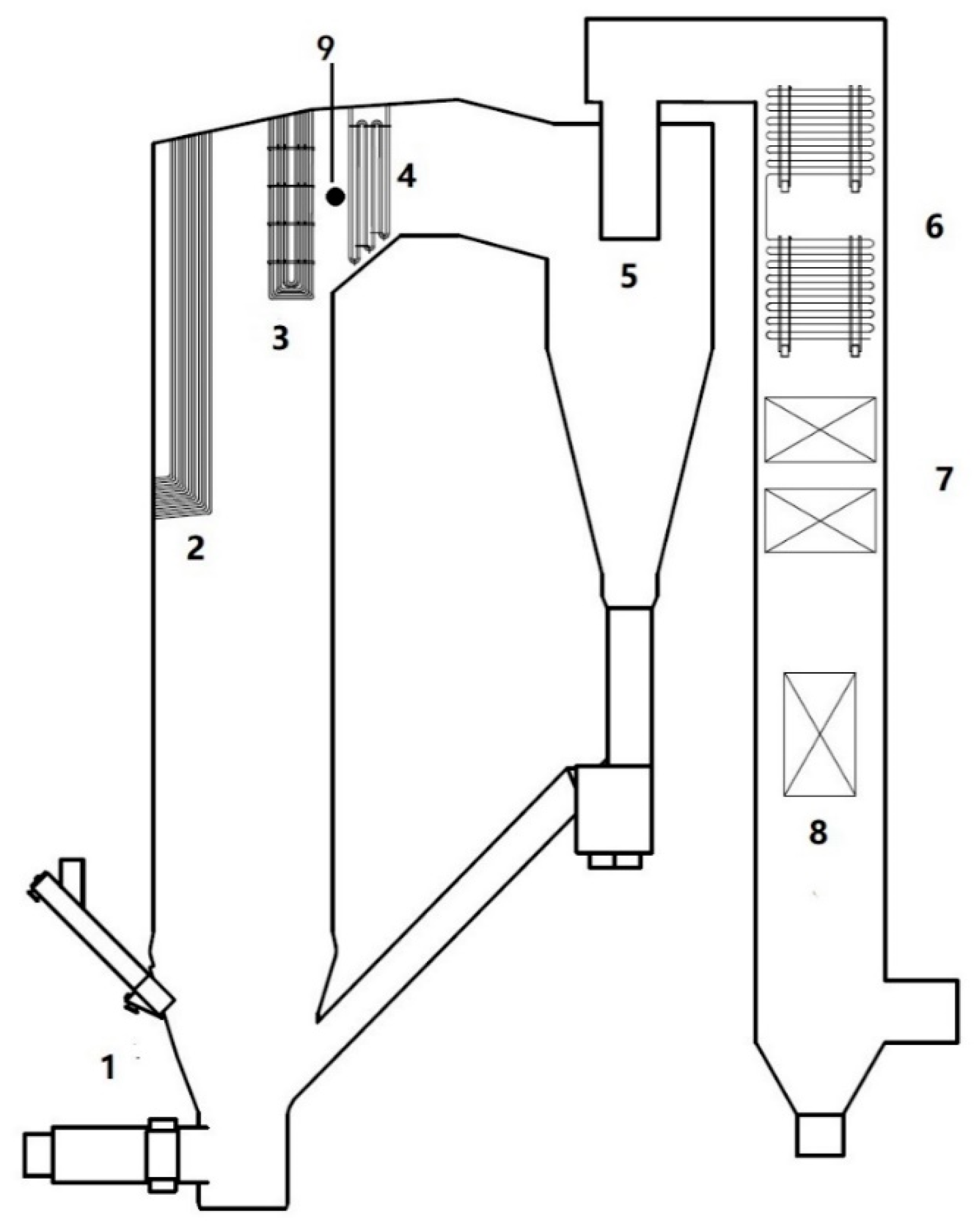
2.1. MW Biomass CFB Boiler
2.2. Fuel
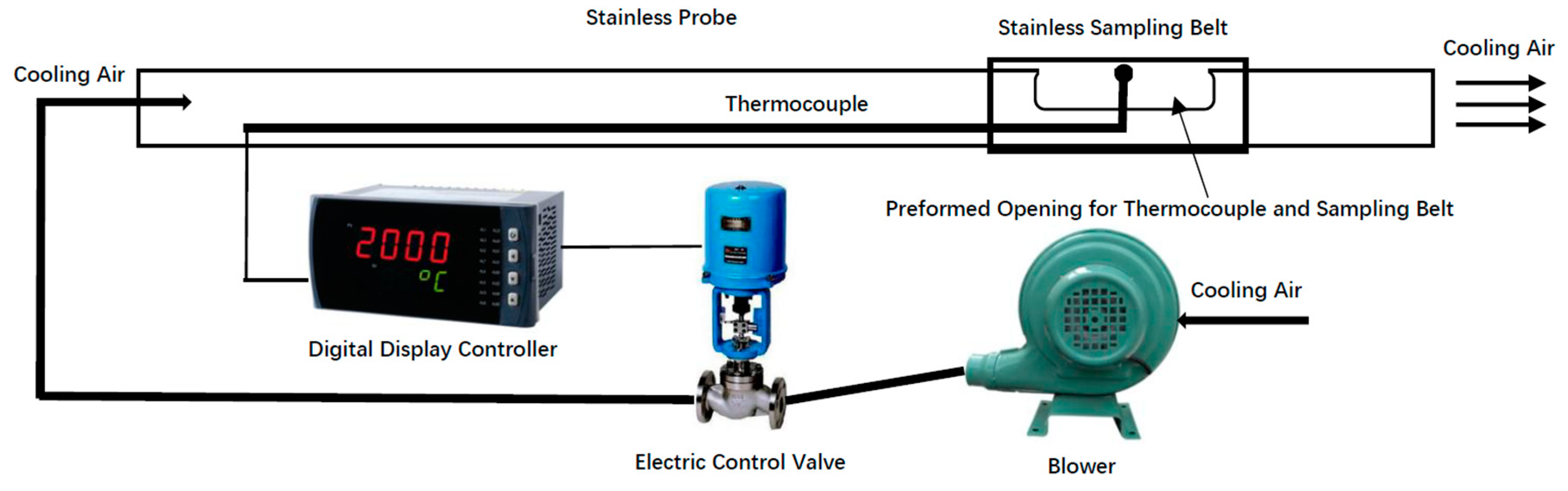
2.3. Collection and Analysis of Deposits
3. Results and Discussion
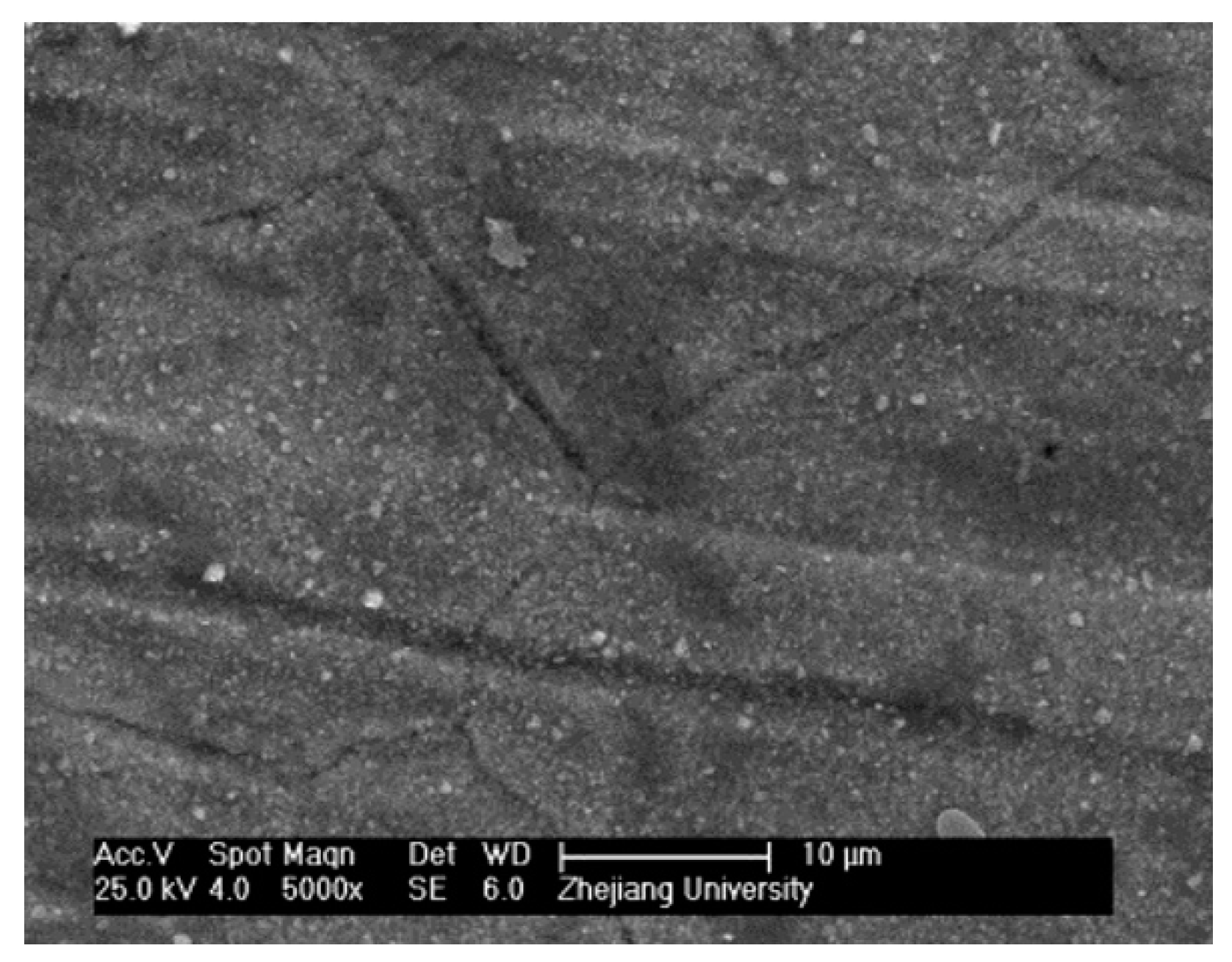
3.1. Initial Deposition
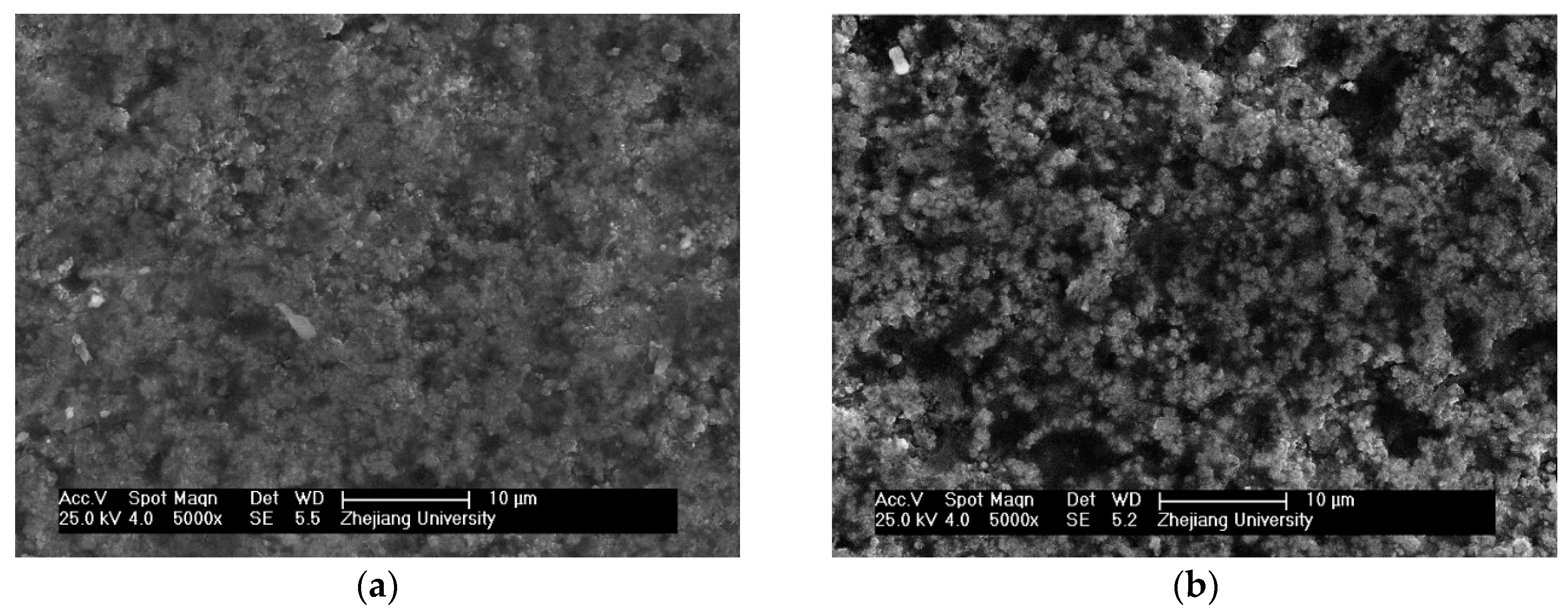
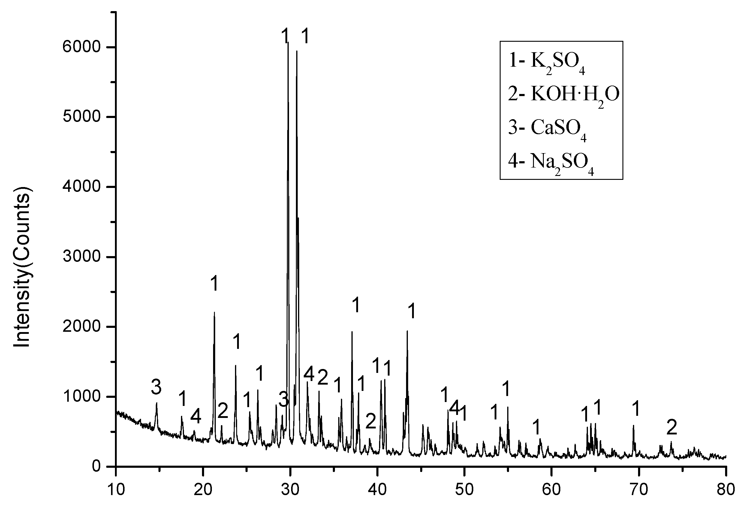
3.2. Migration and Deposition of Alkali Metal
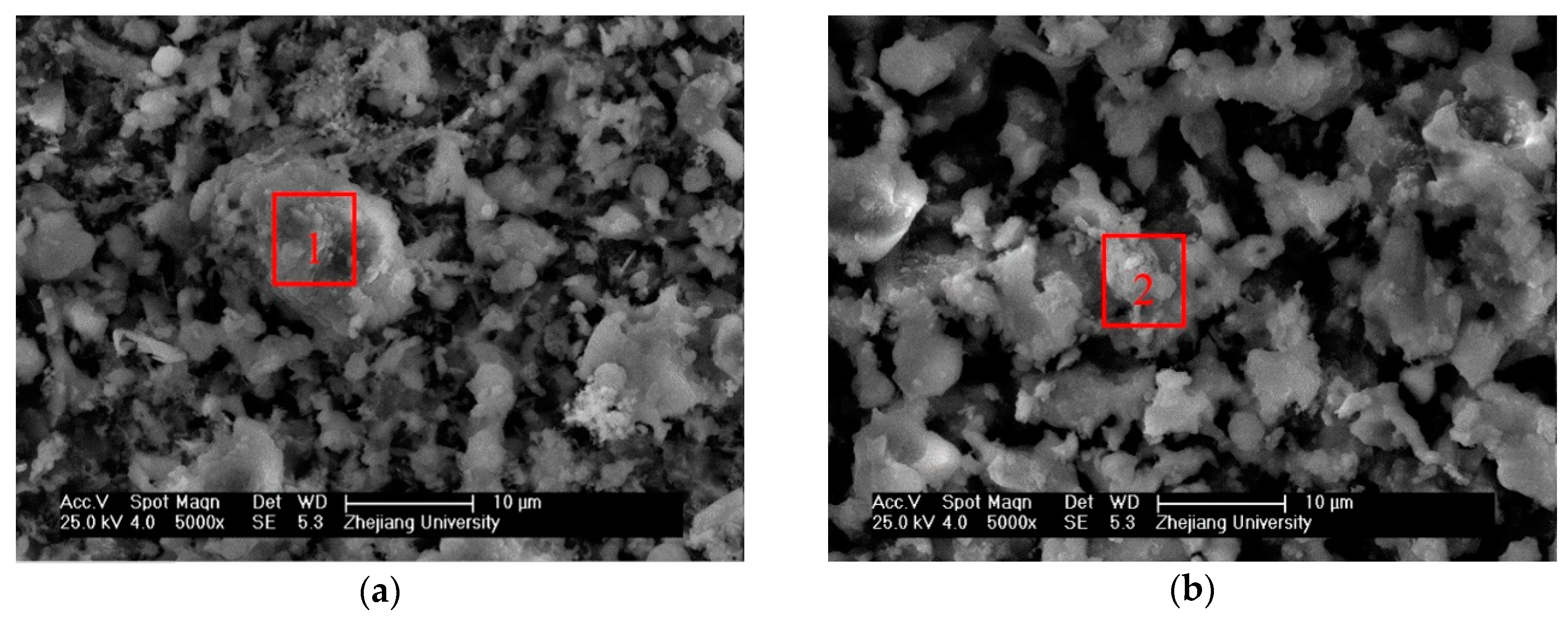
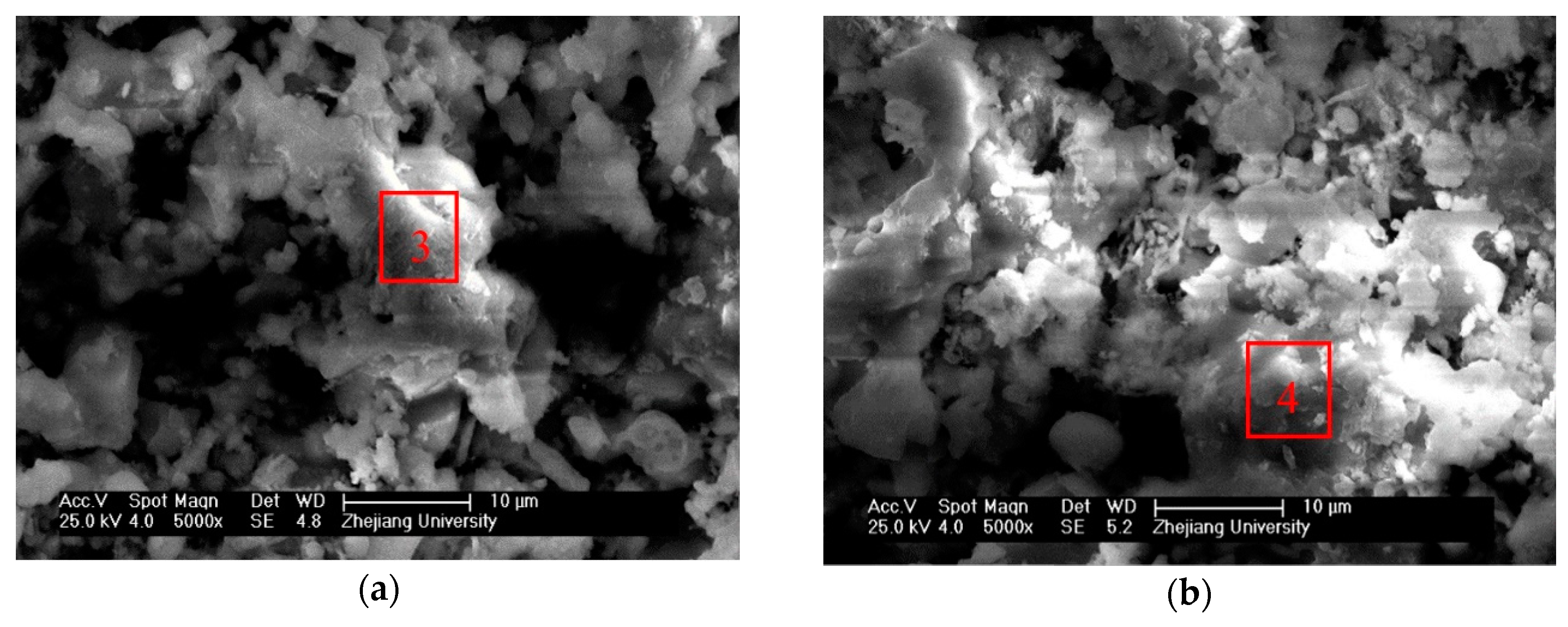
3.3. Development of Deposition
4. Conclusions
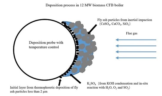
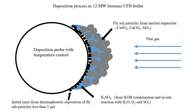
- Initial deposition,In the initial stage, the temperature gradient leads to the deposition of fine particles from the flue gas through thermophoretic deposition.
- Condensation of KOH,Under the condition of a relatively low combustion temperature, low Cl content and high moisture content, K in biomass fuel will release into the gas phase mainly in the form of KOH. In the second stage, after the initial deposition, the surface becomes rough, leading to an acceleration of gas phase KOH condensation on the deposits surface. Then, KOH reacts with H2O, O2 and SO2 in flue gas to form the enrichment of K2SO4 in deposits.
- Inertial impact of fly ash,In the third stage, the rougher surface allows fly ash to deposit through inertial impact. At the same time, with the thickening of the deposition layer, the outer layer temperature increases, leading to a significant reduction in KOH condensation rate. Thus, the elemental composition of the deposit’s surface shows an overall trend of K decreasing and Ca increasing.
Author Contributions
Funding
Conflicts of Interest
References
- Li, L.; Yu, C.; Huang, F.; Bai, J.; Fang, M.; Luo, Z. Study on the deposits derived from a biomass circulating fluidized-bed boiler. Energy Fuels 2012, 26, 6008–6014. [Google Scholar] [CrossRef]
- Zajac, G.; Szyszlak-Barglowicz, J.; Golebiowski, W.; Szczepanik, M. Chemical characteristics of biomass ashes. Energies 2018, 11, 2885. [Google Scholar] [CrossRef]
- Vassilev, S.V.; Baxter, D.; Andersen, L.K.; Vassileva, C.G. An overview of the composition and application of biomass ash. Part 1. Phase-mineral and chemical composition and classification. Fuel 2013, 105, 40–76. [Google Scholar] [CrossRef]
- Chen, C.; Yu, C.; Zhang, H.; Zhai, X.; Luo, Z. Investigation on K and Cl release and migration in micro-spatial distribution during rice straw pyrolysis. Fuel 2016, 167, 180–187. [Google Scholar] [CrossRef]
- Tchapda, A.H.; Pisupati, S.V. A review of thermal co-conversion of coal and biomass/waste. Energies 2014, 7, 1098–1148. [Google Scholar] [CrossRef]
- Jensen, P.A.; Frandsen, F.J.; Dam-Johansen, K.; Sander, B. Experimental investigation of the transformation. and release to gas phase of potassium and chlorine during straw pyrolysis. Energy Fuels 2000, 14, 1280–1285. [Google Scholar] [CrossRef]
- Bjorkman, E.; Stromberg, B. Release of chlorine from biomass at pyrolysis and gasification conditions. Energy Fuels 1997, 11, 1026–1032. [Google Scholar] [CrossRef]
- Knudsen, J.N.; Jensen, P.A.; Dam-Johansen, K. Transformation and release to the gas phase of Cl, K, and S during combustion of annual biomass. Energy Fuels 2004, 18, 1385–1399. [Google Scholar] [CrossRef]
- Wang, G.; Jensen, P.A.; Wu, H.; Frandsen, F.J.; Sander, B.; Glarborg, P. Potassium capture by Kaolin, Part 1: KOH. Energy Fuels 2018, 32, 1851–1862. [Google Scholar] [CrossRef]
- Wang, G.; Jensen, P.A.; Wu, H.; Frandsen, F.J.; Sander, B.; Glarborg, P. Potassium capture by Kaolin, Part 2: K2CO3, KCI, and K2SO4. Energy Fuels 2018, 32, 3566–3578. [Google Scholar] [CrossRef]
- Jeong, T.; Sh, L.; Kim, J.; Lee, B.; Jeon, C. Experimental investigation of ash deposit behavior during co-combustion of bituminous coal with wood pellets and empty fruit bunches. Energies 2019, 12, 2087. [Google Scholar] [CrossRef]
- Jin, X.; Ye, J.; Deng, L.; Che, D. Condensation behaviors of potassium during biomass combustion. Energy Fuels 2017, 31, 2951–2958. [Google Scholar] [CrossRef]
- Niu, Y.; Zhu, Y.; Tan, H.; Hui, S.; Jing, Z.; Xu, W. Investigations on biomass slagging in utility boiler: Criterion numbers and slagging growth mechanisms. Fuel Process. Technol. 2014, 128, 499–508. [Google Scholar] [CrossRef]
- Miles, T.R.; Miles, T.R.; Baxter, L.L.; Bryers, R.W.; Jenkins, B.M.; Oden, L.L. Boiler deposits from firing biomass fuels. Biomass Bioenerg. 1996, 10, 125–138. [Google Scholar] [CrossRef]
- Sandberg, J.; Karlsson, C.; Fdhila, R.B. A 7 year long measurement period investigating the correlation of corrosion, deposit and fuel in a biomass fired circulated fluidized bed boiler. Appl. Energy 2011, 88, 99–110. [Google Scholar] [CrossRef]
- Baxter, L.L.; Miles, T.R.; Miles, T.R.; Jenkins, B.M.; Milne, T.; Dayton, D.; Bryers, R.W.; Oden, L.L. The behavior of inorganic material in biomass-fired power boilers: Field and laboratory experiences. Fuel Process. Technol. 1998, 54, 47–78. [Google Scholar] [CrossRef]
- Jensen, P.A.; Frandsen, F.J.; Hansen, J.; Dam-Johansen, K.; Henriksen, N.; Horlyck, S. SEM investigation of superheater deposits from biomass-fired boilers. Energy Fuels 2004, 18, 378–384. [Google Scholar] [CrossRef]
- Valmari, T.; Lind, T.M.; Kauppinen, E.I.; Sfiris, G.; Nilsson, K.; Maenhaut, W. Field study on ash behavior during circulating fluidized-bed combustion of biomass. 2. Ash deposition and alkali vapor condensation. Energy Fuels 1999, 13, 390–395. [Google Scholar] [CrossRef]
- Zhou, H.; Jensen, P.A.; Frandsen, F.J. Dynamic mechanistic model of superheater deposit growth and shedding in a biomass fired grate boiler. Fuel 2007, 86, 1519–1533. [Google Scholar] [CrossRef]
- Tobiasen, L.; Skytte, R.; Pedersen, L.S.; Pedersen, S.T.; Lindberg, M.A. Deposit characteristic after injection of additives to a Danish straw-fired suspension boiler. Fuel Process. Technol. 2007, 88, 1108–1117. [Google Scholar] [CrossRef]
- Zbogar, A.; Jensen, P.A.; Frandsen, F.J.; Hansen, J.; Glarborg, P. Experimental investigation of ash deposit shedding in a straw-fired boiler. Energy Fuels 2006, 20, 512–519. [Google Scholar] [CrossRef]
- Bashir, M.S.; Jensen, P.A.; Frandsen, F.; Wedel, S.; Dam-Johansen, K.; Wadenback, J.; Pedersen, S.T. Suspension-firing of biomass. Part 1: Full-scale measurements of ash deposit build-up. Energy Fuels 2012, 26, 2317–2330. [Google Scholar] [CrossRef]
- Madhiyanon, T.; Sathitruangsak, P.; Sungworagarn, S.; Pipatmanomai, S.; Tia, S. A pilot-scale investigation of ash and deposition formation during oil-palm empty-fruit-bunch (EFB) combustion. Fuel Process. Technol. 2012, 96, 250–264. [Google Scholar] [CrossRef]
- Retschitzegger, S.; Gruber, T.; Brunner, T.; Obernberger, I. Short term online corrosion measurements in biomass fired boilers. Part 1: Application of a newly developed mass loss probe. Fuel Process. Technol. 2015, 137, 148–156. [Google Scholar] [CrossRef]
- Retschitzegger, S.; Gruber, T.; Brunner, T.; Obernberger, I. Short term online corrosion measurements in biomass fired boilers. Part 2: Investigation of the corrosion behavior of three selected superheater steels for two biomass fuels. Fuel Process. Technol. 2016, 142, 59–70. [Google Scholar] [CrossRef]
- Hansen, L.A.; Nielsen, H.P.; Frandsen, F.J.; Dam-Johansen, K.; Horlyck, S.; Karlsson, A. Influence of deposit formation on corrosion at a straw-fired boiler. Fuel Process. Technol. 2000, 64, 189–209. [Google Scholar] [CrossRef]


| Item | Symbol | Blended Biomass Fuel |
|---|---|---|
| Proximate analysis | moisture (%, ad) | 7.66 |
| ash (%, ad) | 5.04 | |
| volatile (%, ad) | 69.4 | |
| fixed carbon (%, ad) | 17.9 | |
| Ultimate analysis | C (%, ad) | 43.78 |
| H (%, ad) | 4.59 | |
| N (%, ad) | 1.35 | |
| S (%, ad) | 0.09 | |
| O (%, ad) | 37.49 | |
| Heating value | Q (kJ/kg, ad) | 18312 |
| Inorganic constituent (dry basis) | K (%) | 0.41 |
| SO42- (%) | 0.45 | |
| Cl (%) | 0.09 |
| C | O | Na | Mg | Al | Si | P | S | Cl | K | Ca | Fe | |
|---|---|---|---|---|---|---|---|---|---|---|---|---|
| Fly ash | 16.61 | 30.91 | 1.30 | 2.05 | 5.38 | 9.72 | 0.72 | 2.40 | 0.87 | 7.37 | 19.26 | 3.40 |
| Element | Na | Mg | Al | Si | P | S | Cl | K | Ca |
|---|---|---|---|---|---|---|---|---|---|
| Deposits of 1 h | 4.35 | 15.46 | 4.56 | 12.16 | 5.37 | 19.93 | 2.85 | 3.34 | 32.02 |
| Deposits of 2 h | 1.83 | 16.18 | 4.58 | 11.84 | 5.26 | 18.25 | 1.83 | 2.44 | 37.79 |
| Fly ash < 2 μm | 2.27 | 18.01 | 4.37 | 12.11 | 5.13 | 19.09 | 1.51 | 2.09 | 35.41 |
| Element | Na | Mg | Al | Si | P | S | Cl | K | Ca |
|---|---|---|---|---|---|---|---|---|---|
| 5 h | 3.97 | 5.80 | 4.06 | 15.14 | 1.11 | 26.32 | 0.00 | 22.84 | 20.75 |
| 15 h | 4.66 | 3.87 | 3.34 | 9.78 | 1.46 | 25.20 | 0.25 | 34.36 | 17.07 |
| Spot 1 | 1.18 | 1.08 | 1.25 | 2.84 | 1.08 | 34.91 | 0.57 | 27.59 | 29.46 |
| Spot 2 | 1.92 | 1.11 | 1.21 | 2.97 | 0.56 | 34.85 | 0.00 | 31.25 | 26.10 |
| Element | Na | Mg | Al | Si | P | S | Cl | K | Ca |
|---|---|---|---|---|---|---|---|---|---|
| 24 h | 1.53 | 3.72 | 1.81 | 7.49 | 1.03 | 28.72 | 0.00 | 26.18 | 29.54 |
| 48 h | 1.25 | 5.48 | 1.97 | 9.47 | 1.15 | 25.49 | 0.00 | 20.58 | 34.62 |
| Spot 3 | 0.45 | 1.61 | 0.46 | 1.17 | 0.41 | 37.28 | 0.00 | 28.99 | 29.62 |
| Spot 4 | 0.75 | 1.00 | 0.42 | 1.69 | 0.42 | 37.14 | 0.07 | 28.19 | 30.29 |
© 2020 by the authors. Licensee MDPI, Basel, Switzerland. This article is an open access article distributed under the terms and conditions of the Creative Commons Attribution (CC BY) license (http://creativecommons.org/licenses/by/4.0/).
Share and Cite
Zhang, H.; Yu, C.; Luo, Z.; Li, Y. Investigation of Ash Deposition Dynamic Process in an Industrial Biomass CFB Boiler Burning High-Alkali and Low-Chlorine Fuel. Energies 2020, 13, 1092. https://doi.org/10.3390/en13051092
Zhang H, Yu C, Luo Z, Li Y. Investigation of Ash Deposition Dynamic Process in an Industrial Biomass CFB Boiler Burning High-Alkali and Low-Chlorine Fuel. Energies. 2020; 13(5):1092. https://doi.org/10.3390/en13051092
Chicago/Turabian StyleZhang, Hengli, Chunjiang Yu, Zhongyang Luo, and Yu’an Li. 2020. "Investigation of Ash Deposition Dynamic Process in an Industrial Biomass CFB Boiler Burning High-Alkali and Low-Chlorine Fuel" Energies 13, no. 5: 1092. https://doi.org/10.3390/en13051092
APA StyleZhang, H., Yu, C., Luo, Z., & Li, Y. (2020). Investigation of Ash Deposition Dynamic Process in an Industrial Biomass CFB Boiler Burning High-Alkali and Low-Chlorine Fuel. Energies, 13(5), 1092. https://doi.org/10.3390/en13051092