Review

Power Quality Phenomena in Electric Railway Power Supply Systems: An Exhaustive Framework and Classification

1
Department of Energy, Politecnico di Milano, 20156 Milan, Italy
2
School of Railway Engineering, Iran University of Science and Technology, Tehran 16844, Iran
*
Author to whom correspondence should be addressed.
Energies 2020, 13(24), 6662; https://doi.org/10.3390/en13246662
Submission received: 14 November 2020 / Revised: 7 December 2020 / Accepted: 14 December 2020 / Published: 17 December 2020
(This article belongs to the Special Issue Power Quality in Electrified Transportation Systems)

Abstract

:
Electric railway power systems (ERPS) as one of the most critical and high-power end-user loads of utility grids are characterized by outlandish power quality (PQ) problems all over the world. The extension and evolution of different supply topologies for these systems has resulted in significant and various forms of distortions in network voltage and current in all ERPS, the connected power system, and adjacent consumers. During the last years, numerous studies have been offered to investigate various aspects of PQs in a specific supplying topology. Variation in the supply structure of the ERPS and different types of locomotives has propelled the observation of different PQ phenomena. This versatility and development have led to confront considerable types of two-way interactive interfaces as well as reliability and PQ problems in ERPS. In addition, the lack of standards explicitly dedicated to ERPS has added to the ambiguity and complexity of this issue. In this paper, an extensive review of PQ distortions and phenomena in different configurations of ERPS is proposed and a systematic classification is presented. More than 140 scientific papers and publications are studied and categorized which can provide a fast review and a perfect perspective on the status of PQ indexes for researchers and experts.

1. Introduction

The outstanding characteristics of electric railway power systems (ERPS) such as safe transport, high-power/capacity, high-speed, great reliability and resilience, and environment-friendly manner make them one of the popular and promising transport systems [1]. These systems have experienced considerable improvement and evolution during the last decades. Historical, geographical, and economical reasons have led to the establishment of different ERPSs structures in various countries [2]. This development and diversity have resulted in facing different forms of distortions and power quality (PQ) issues not only in ERPSs, but also in the supplier utility grid and other adjacent loads. Generally, PQ issues in ERPSs have been investigated individually by dividing the systems into three areas of DC, 16.67/25 Hz AC and 50/60 Hz AC. The DC type ERPSs introduced as the primary technology with lower requirements and capacity in transportation electrification. Urban railway systems including subways, trams, and light-rails are the most popular types of DC systems. Voltage/current harmonics, waveform transients, system imbalance, and low power factor are the foremost phenomena which are reported in the so-far published researches related to these systems [3,4,5]. The hardness and complexity of AC motors to supply the high-power traction loads with the industrial frequency caused to establishment of 16.67/25 Hz system taking advantage of rotary frequency converters. The frequency transient, stability problems driven by electromechanical transients, and amplification of negative sequence current or imbalance in synchronous generators are the main PQ issues of these systems [6,7,8]. With the subsequent developments of technologies and high demands for transportation, industrial frequency-based ERPSs have become promoted and more popular. Primary systems in this context are established based on 1 × 25 kV ERPSs, which can be found in different forms of without return conductor, with return feeder, and with booster transformer. The most important PQ phenomena reported in these systems include imbalance, harmonics, low-frequency oscillations, low power factor, voltage drops, and electromagnetic interference (EMI) based issues due to the return currents and arcing [9,10,11]. The next-generation AC ERPSs were adopted based on autotransformer based 2 × 25 kV systems concentrating on mitigation of EMI issues, voltage drops, and arcing problems [12,13,14]. The PQ problems related to AC ERPSs are so crucial that different configurations of passive and active compensation technologies [15,16,17,18] are proposed to mitigate them in the literature. Meanwhile, extensive studies are underway regarding replacing existing systems with modern power electronics (PE)-based ERPSs as co-phase, advanced co-phase, and different types of VSC and MMCs [19,20,21,22,23]. These ERPSs are recognized as green types because the VSCs can control their output voltage and currents matching with the desired PQ. During the last years, multiple studies have been addressed some of PQ indexes in a specific supplying ERPS. In [24,25] PQ analysis in high-speed railways (HSR) and 1 × 25 kV ERPSs have been carried out. Mariscotti has analyzed PQ issues in 16.67 Hz and DC ERPSs specifically in terms of conditioning and measurement in [26,27]. The analysis in 2 × 25 kV ERPSs emphasizing EMI phenomena has been carried out in [28]. In [29] an inclusive study of harmonic problems in ERPSs has been studied. However, there is still a lack of a comprehensive study and framework that addresses all PQ phenomena and classifies them based on ERPS types. In addition, unlike the power systems, for which multiple standards and resources have been developed, the ERPS suffers from a deficiency of a comprehensive and all-encompassing resource. This has been reinforced the ambiguity and complexity of PQ analysis in ERPSs. Meanwhile, selecting a suitable method to relieve PQ issues needs a complete knowledge and identification of main sources, features, influencing factors, and occurrence environment. Motivated by the above-mentioned shortcomings, this paper presents an exhaustive definition and classification of PQ indexes and distortions together with a brief review of various ERPSs configuration and the classified reported PQ phenomena in literature based on each ERPS type. The rest parts of the paper are structured as follows: Section 2 describes and portrays all the PQ phenomena and influencing factors in ERPS. In Section 3 the investigation of phenomena based on the classified ERPS type is presented. In Section 4 the classification of reported PQ phenomena in literature is discussed. Finally, Section 5 concludes the paper.

2. Power Quality Phenomena in ERPS

PQ issues, disturbances, or phenomena are terms used to characterize voltage or current deviations from its ideal waveform. Different forms of PQ phenomena have been occurred all around the world according to the designed and operating structure of ERPS. In this section, the reported PQ indexes in EPRSs together with originated and influencing factors are described and categorized based on their type.

2.1. System Unbalance

One of the most important and common PQ phenomena in EPRSs is system unbalance which emanated from single-phase power supplying AC EPRS [30]. In normal conditions, when the network is balanced, the three-phase voltages/currents are identical in magnitude and the phase differences are 120°. When the system is gotten imbalanced, the three-phase voltages/currents are not the same in magnitude and the phases are unsymmetrical.
So far, different definitions of unbalance have been proposed in a three-phase system. The issue of unbalance can be categorized into two subjects: voltage unbalance and current unbalance. These voltage and current unbalances may cause extra losses, communication interference, motor overheating, and malfunction of relays [30,31,32,33,34,35,36,37]. The degree of these unbalances depends on the train’s movement, the tractive profile of electric locomotives, the type of traction substation transformer (TST) [35], and the power-supply scheme. Numerous problems due to imbalance motivated experts to look at it with a more specialized view and to propose standards for measuring the imbalance. The three key definitions of imbalance are provided by the IEEE [38], IEC [39], and NEMA [40] over the years.
  • IEEE std 112-1991
In 1991, the IEEE introduced its second definition of voltage imbalance under standard 112 to define an indicator for voltage imbalance, in which the maximum deviation of the effective value of the phase voltage from the mean effective value of the phase voltage, relative to the average value of the phase voltage according to Equation (1) [38]. Where PVUR denotes phase voltage unbalance rate.
% P V U R = max { | V a V a v g | , | V b V a v g | , | V c V a v g | } V a v g × 100
V a v g = V a + V b + V c 3
  • IEC 60034-26
The IEC standard defines voltage imbalance as the ratio of the negative or zero sequence component to the positive sequence component. In simple words, it is a voltage variation in a power system in which the voltage amplitudes or the phase angle differences between them are not equal. The negative and positive sequence of line voltage can be calculated using the Fortescue matrix as Equation (4) [39]. Where εV denotes voltage imbalance ratio.
% ε V = V V + × 100 = V a b V a b + × 100
( V a b V a b + V a b ) = 1 3 ( 1 1 1 1 a a 2 1 a 2 a ) ( V a b V b c V c a )
{ V a b = V a V b V b c = V b V c V c a = V c V a
  • ANSI/NEMA Standard MG1-1993
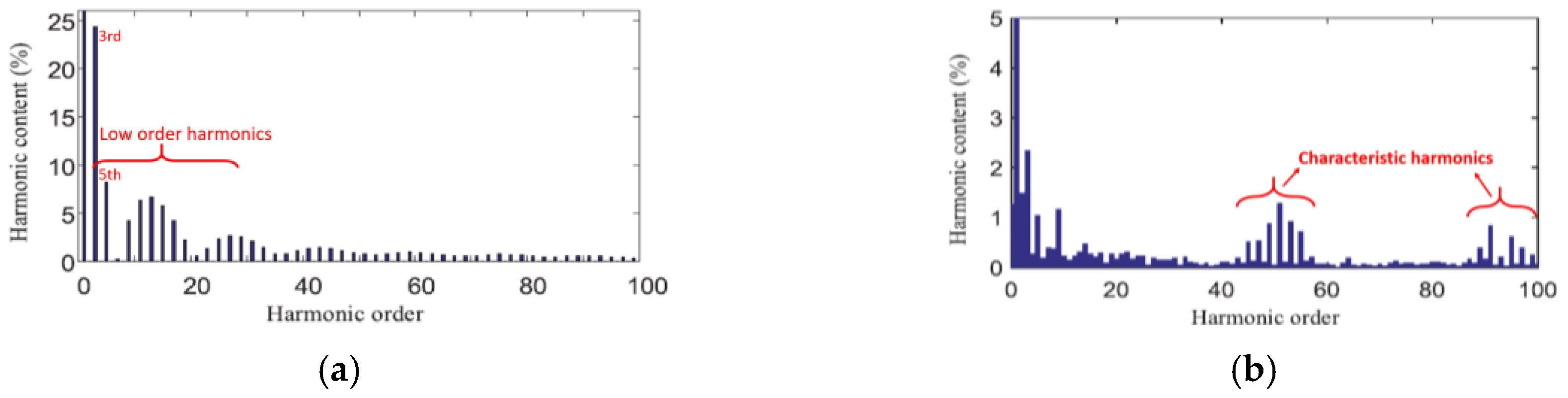
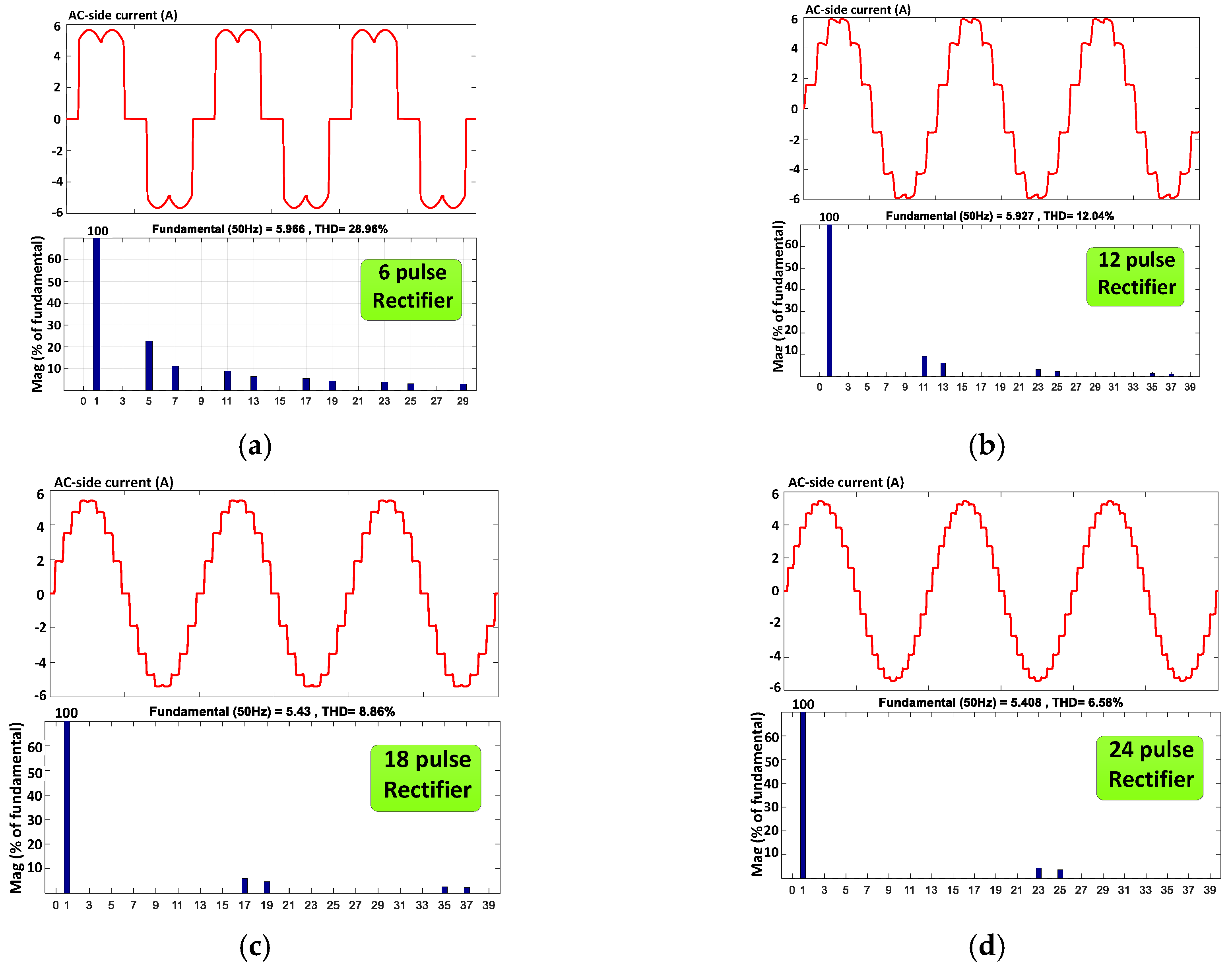
In 1993, NEMA introduced a standard for unbalance that included only the effective magnitude of line-by-line voltages. In this definition, the maximum deviation of the effective value of line voltages from the average effective value of line voltages, compared to the average value of line voltages as follows [40]. Where LVUR denotes line voltage unbalance rate.
% L V U R = max { | V a b V a v g | , | V b c V a v g | , | V c a V a v g | } V a v g × 100
In general, the voltage/currents unbalance factor (VUF/CUF) is defined to measure the intensity of the system unbalance as given in Equations (7) and (8).
% V U F = V V + × 100
% C U F = I I + × 100
where V and I are the negative sequence voltage and currents, and V+ and I+ present the positive sequence voltage and currents. A higher amount of factors declare a high value of negative-sequence current (NSC) injected to the ERPS. Depending on the adopted TST type in ERPS, the factors are changed. Figure 1 illustrates the measured real imbalance situation of Wuhan–Guangzhou high-speed electrified railway [41].

2.2. Harmonics

The ERPS is one of the main harmonic provenances in the public power grid. Depending on the supplying topology type, different forms of harmonic phenomena can emerge.

2.2.1. Low Order Harmonics

Low order harmonics (LOH) known also as main harmonics are the most critical kind of harmonics in ERPS. They have been noticed as the motivation of numerous functioning obstacles both to the power grid and ERPS. The amplitude of the LOH is greater than the other harmonic spectrum ingredients. Accordingly, the negative efficacy of LOH can decline the fundamental signal amplitude impressively. Intensive shaking and noises in motors and generators, exceeding of heat and loss in transformers and transmission lines, harmful impacts and destructions in relays and other protection systems, and instability of power network are some of their main adversely effects [42]. In general, the main LOH in ERPS can be classified into three categories as follows.
  • Background Harmonics
This category also known as internal harmonics of ERPS is generated by the power supplying system in the absence of operational trains. In addition, they can be turned out by adjacent contiguous nonlinear loads linked to the joint busbar as a point of common coupling. The harmonic spectrum ranges for background harmonics are pretty much odd inherent harmonics like 3rd, 5th, 7th, …, 19th [43,44].
  • Train Internal Harmonics
In AC ERPS, trains and their PE converter based interior driving systems are assumed in the guise of basic harmonic origination. Most functioning trains in the world even now contain thyristor/diode-based PE converters in their configuration, which turn out current harmonics and accordingly voltage harmonic and distortion [24,45,46,47]. The low order ingredients as 3rd, 5th, 7th,…, 21st, and 23rd are the most highlighted ones measured in these kinds of trains. Figure 2a demonstrates the harmonic content of conventional thyristor/diode-based trains measured in the ERPS. Conversely, the modern trains equipped with four-quadrant converters (4QCs) evolve less harmonic pollution thanks to the adoption of high switching frequency (pulse-width modulation) (PWM). However, as shown in Figure 2b even the amplitude of LOH has declined significantly (the vertical axes scale has been decreased), the high order components around switching frequency are considered as a substantial problem. These components are known as the characteristic harmonics which will be explained in the next sections.
  • DC Substation Harmonics
In addition to the trains, the internal structure of ERPS is considered as the foremost and significant harmonic origination in the power grid. Contingent on the AC or DC type supplying system, type of converter in traction power substation (TPSS) and voltage level, various forms of harmonic phenomena can arise. Metro (subway) EPRSs which are fed by multi-pulse conventional rectification substations are a pivotal reason for LOH distortion in the primary side of the grid [48,49,50,51]. Moreover, DC traction motor based traditional locomotives functioning in AC systems are massive harmonic contamination loads regarding the high-power utilization of nonlinear rectification converter. The harmonic ingredients in the primary-side current of AC/DC substations can be defined as the function of pulse number:
h = k p ± 1   k N
where p is the pulse number of converter and h expresses the harmonic order. The popular n-pulse rectifier based traditional substations in EPRSs is 6, 12, 18, and 24 pulses. The primary-side current waveforms and fast Fourier transform (FFT) investigation for these types of TPSSs are simulated and demonstrated on a small scale in Figure 3. As can be seen from the figures, by increasing the number of pulses, the total harmonic distortion (THD) percentage has been decreased and the harmonic components are shifted from low orders to high orders.

2.2.2. Inter-Harmonics

In ERPS inter-harmonics (InH) are emerged by AC motors controlled by variable frequency drives (VFDs). They are related to the fundamental main frequency (fo) and the input AC frequency (fi) which supplies VFD. These kinds of harmonics are realized between the typical and characterized harmonics of the VFDs. The main reason for occurrence is the compilation among the switching tasks applied to invert the DC-link voltage to the three-phase AC voltage with the DC current ripple [52,53,54,55]. The frequency of the inter-harmonics can be characterized as
f I h = | n p i f i ± m p o f o |   n ,   m Z
where pi and po denote the number of pulses in the rectification and inversion process. The inter-harmonics afford pulsating torque harmonics, stimulate a linked traction motor and torsional resonance path, wheel wear, and a critical impact on the torsional behavior of the entire train.

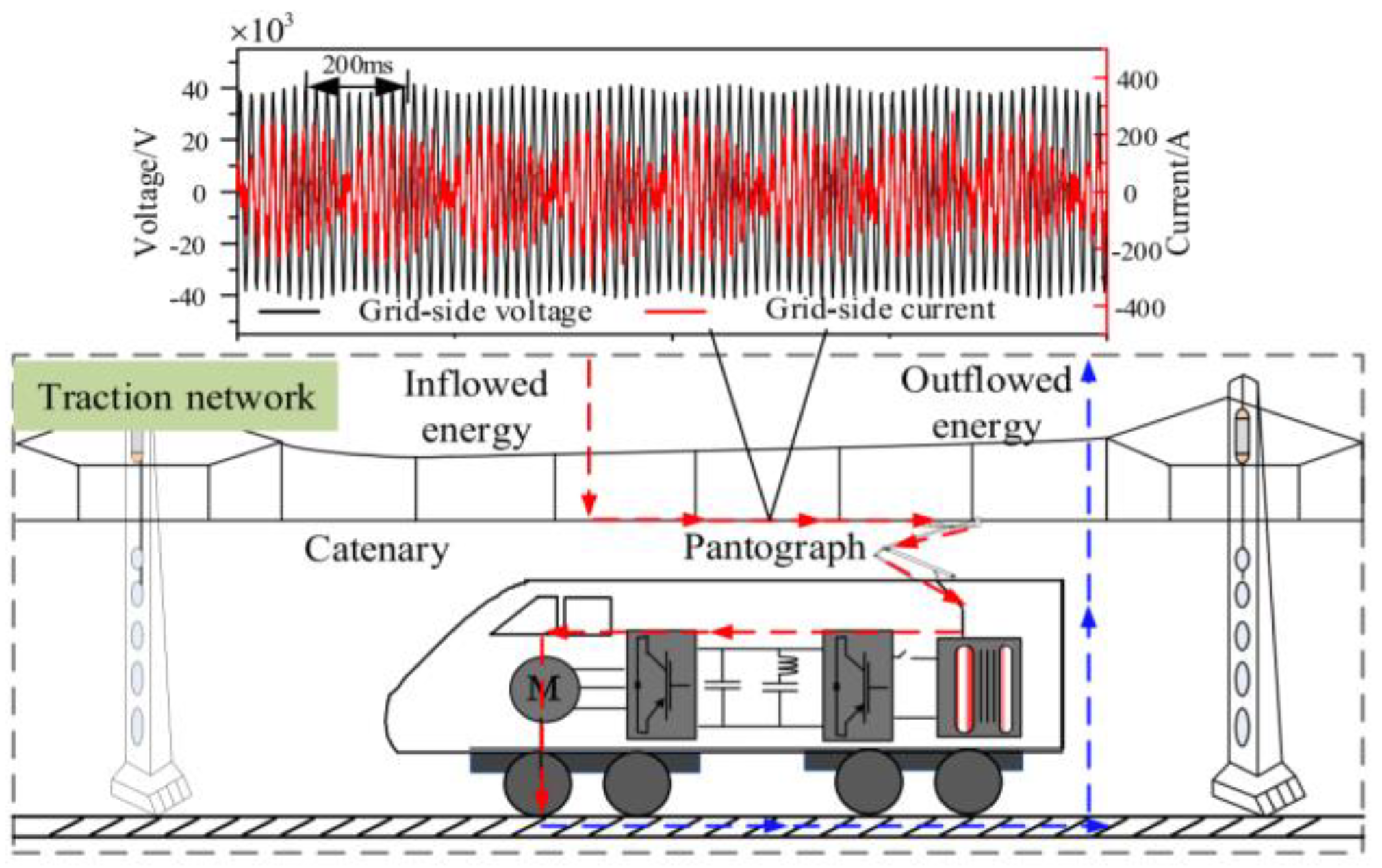
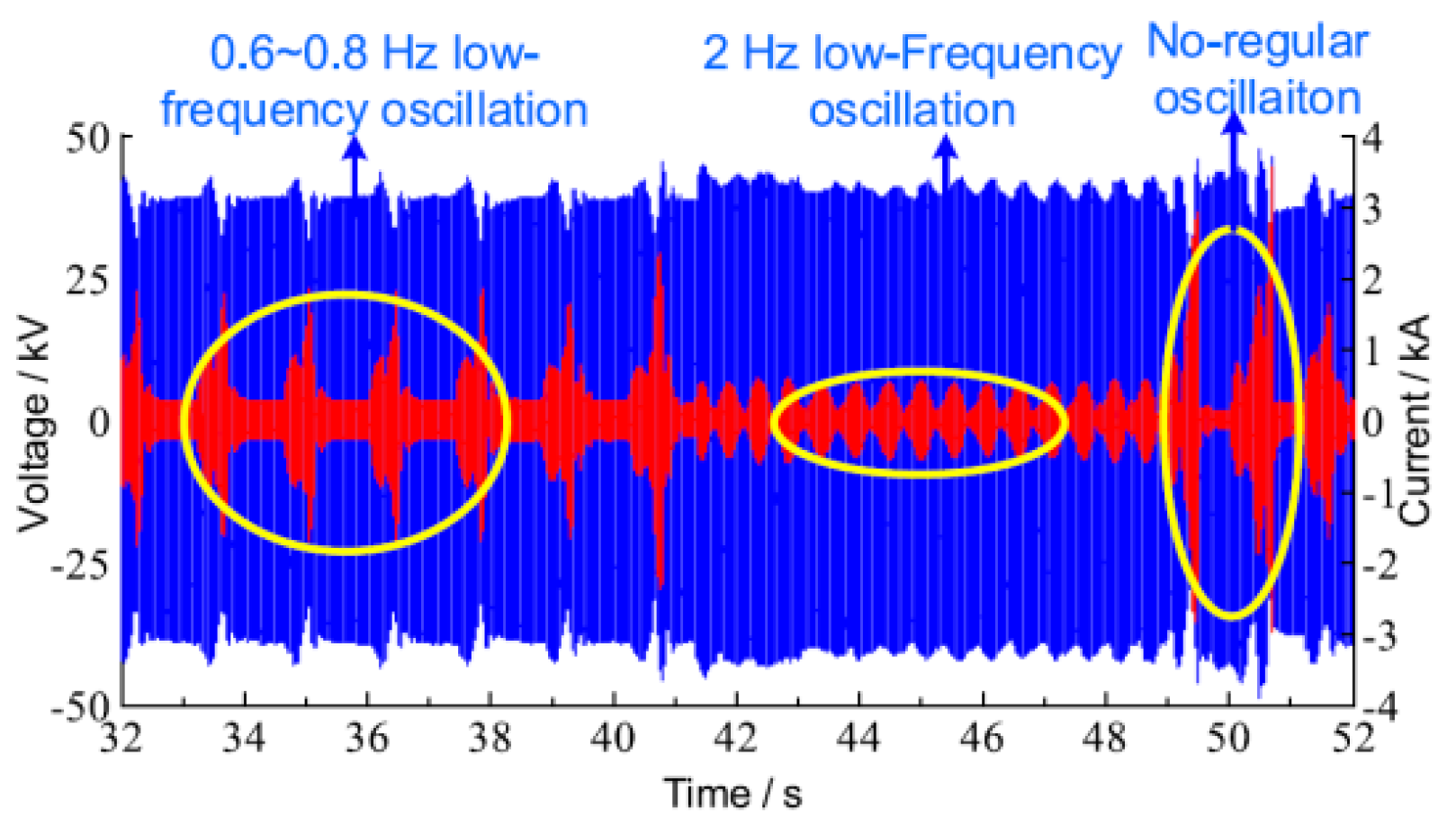
2.2.3. Low Frequency Oscillation

The low frequency oscillation (LFO) is an impermanent phenomenon and a vehicle-grid interlinkage issue situated by the impedance inconsistency between the ERPS and the modern trains particularly those equipped with 4QCs. Furthermore, LFO can be produced by the rotary frequency converter (RFC) used in several European ERPS [56,57]. In LFO circumstances the voltage and current demonstrate a magnitude and phase oscillation. It can lead to several significant problems, such as the conservation system breakdown, over voltage and current, damage to the onboard devices, and even divergence oscillation of voltage and current leading to railway accidents and obstruction or inconsistency issues [56,57,58,59,60,61,62,63,64,65]. Three types of LFO scenarios are defined in the literature depending on the structure of ERPS type. Figure 4. demonstrates the LFO in catenary voltage and currents.
  • LFO in RFC based ERPS
In the age of starting railway electrification, based on the low requests, existing low-capacity power grids, and consequences regarding using of powerful motors in industrial frequency, the low-frequency systems got more attention. These kinds of ERPS are established in several countries as Austria, Germany, Switzerland, Norway, Sweden, and the USA functioning with a frequency of 16.67 or 25 Hz. The frequency below the power grid frequency demonstrates the urgency of the requirement for RFC. The LFO is primarily measured in these kinds of ERPS. The usual oscillation content in this group is reported in the range of (0.1–0.3) p.u [56,57,58].
  • LFO in ERPS without RFC
The consistently incremental request for passenger and mass transfer as well as subsequent advancement of technologies and power networks promote the construction and development of transformer-based AC systems operating with industrial frequency and without RFCs. The conventional 1 × 25 kV and 2 × 25 kV autotransformer based ERPS are the most popular embraced structures. Notwithstanding, LFO in such a network often occurs by concurrent functioning of multiple trains. The ultra-critical quantity of operating trains which leads to the LFO occurrence is reported approximately 6–8. The usual oscillation content in this group of LFO is reported in the range of (0.01–0.12) p.u [59,60,61,62,63].
  • Irregular LFO
The latter category of LFO is non-periodic and immethodical oscillations that can enhance current and voltage magnitude unfavorably. The irregular LFO has been reported mostly in China [64,65]. It is not possible to assign a special frequency oscillation range for this type of LFO. Figure 5 shows the measured voltage and current waveforms including various types of LFO. As shown in the figure, the most undesirable type is related to irregular LFO with higher current magnitude reinforcement.

2.2.4. Harmonic Resonance

The current LOH produced by trains mainly in modern ERPS can spread all around the power supply networks. Contrarily, the inductance and capacitive specifications of the overhead catenary system (OCS), may make a distributed LC circuit that can lead to parallels or series resonance at the specific frequencies. The interaction of these current harmonics and internal resonance may cause the harmonic resonance (HR) phenomenon at some characteristic frequencies in ERPS. By way of explanation, some harmonic ingredients are strengthened by the resonance. The HR can create serious issues such as drastic voltage distortion, electromagnetic interference in communication and signaling system, overheating and losses, and misdeed of protection equipment [66,67,68,69,70,71,72,73,74,75,76,77,78,79].
Figure 6 illustrates the harmonic spectrums for measured OCS currents/voltages reported in two main HSR lines in China and Italy containing HR phenomenon. This phenomenon which is reported in many countries can be divided into parallel and series scenarios. Generally, the composition of inductive and capacitive features of OCS can lead to either a series resonance (when L and C are in series) or a parallel resonance (when L and C are in parallel).
  • Parallel HR
The parallel HR (PHR) is most likely HR scenario in ERPS due to the inductive and capacitive specification of multi-conductor OCS. The specified frequency oscillation range for PHR based on measurements is between 10 and 55 p.u. The critical HR incidents correlate with the parallel resonance which is the basic concern in TPSS. The PHR has been reported in some countries which are classified based on the order in Table 1.
  • Series HR
The series HR (SHR) is an infrequent HR phenomenon in EPRSs. Functioning of FACT device or conditioners as static VAR compensators, STATCOM and Steinmetz theory may interact with ERPS impedance and create SHR. The specified oscillation content in this group is reported in the range of (3–9) p.u. The SHR has been reported in some countries which are mentioned in Table 1.

2.2.5. Harmonic Instabilities

The most basic factor of harmonic instabilities (HI) genesis is the higher switching frequency of PWM based 4QCs in recent and modern trains. The interplay among the multiple switching frequency and ERPS interior resonance frequency reinforce an intense oscillation with a sort of insignificant damping termed as HI [80,81,82,83,84,85,86,87]. In addition, the high-frequency features of the closed-loop control system for 4QCs including voltage and the current controller can interact with ERPS and originate HI. Accordingly, HI may amplify the voltage and current harmonics and cause the system to be instable. Compared with HR as a stable phenomenon and harmonic reinforcement, the HI is an unstable phenomenon. The specified oscillation content for this phenomenon is dependent on the resonance frequencies.
Nevertheless, according to the measurements and reports, the resonance orders can be in the range of 2nd to 100th with field test intensifications of 23rd to 24th and 47th to 55th [64]. It can lead to critical issues such as overvoltage problems, stimulate some harmonic ingredients, explosion or malfunction of protection devices together with overheating and loss problems. HI phenomenon has been stated in China [64], Switzerland [81], and Italy [82]. Figure 7 demonstrates a measured OCS voltage waveform including HI. For the purpose of having a rapid review and a suitable classification, the harmonic phenomena organization chart together with the frequency range is presented in Figure 8. This figure illustrates an epitome of the harmonic indexes with their different types in ERPS. Meanwhile, the possible per unit range for each phenomenon has been determined and demonstrated. A schematic based comparison together with a technical discussion between harmonic phenomena can be found in [64,80].

2.3. Reactive Power and Low Power Factor

Notwithstanding the application of advanced PWM based trains, the majority of working trains in ERPS all over the world are still based on AC/DC rectifiers using thyristor or diode. This can cause the current distortion in the primary-side of the substation and overlap commutation angle. Therefore, it can reduce the power factor (PF) of the system substantially. On the other side, considering the impacts of ERPS impedance including the inductive reactance features of the OCS, the PF will be reduced by about 1–5%. The low PF in the system can be the origination of many problems including, lower efficiency, high power losses, heating of devices, and high voltage drops across the line [45,88,89,90,91,92,93,94,95]. This is so serious for power grids that fine subscribers with a low power factor of 0.9 in PCC. However, the average amount of PF in ERPS depending on the type of supply is measured in the range of 0.70–0.84 [93]. Figure 9 demonstrates the measurements of PF for three different popular HST trains operating in the world. According to these figures, for the light-loading situation and coasting mode, the amount of PF is proportionally lower and rapidly when the train current/power increase PF reaches close to unity. Power factor is commonly specified by a particular description assuming a balanced situation without harmonics on the system. However, in a real practical system, the PF can be affected by the harmonic components and imbalance condition in the ERPS. Accordingly, the type of traction transformer and its loading characteristics will play an important role to determine the PF in AC ERPS [95]. The performance of popular traction transformers in ERPS is based on the different PF definitions as fundamental PF (PF1), effective PF (PFE), vector PF (PFV), and arithmetic PF (PFE) [95] in IEEE Std-1459 is demonstrated in Table 2. The practical measurement in this table reveals the better performance of Y/d and Scott transformer in presence of harmonics for both balanced and imbalanced conditions.

2.4. Transient Events

PQ phenomena in ERPS includes a wide range of disturbances and different types of deviations in voltage amplitude or waveform. The PQ deviation events/disturbances can be classified based on the disposition of the waveform distortion, duration, rate of rising, and amplitude for each category of electromagnetic disturbances. A comprehensive classification of PQ electromagnetic phenomena for power systems can be found in [96]. However, due to the specific and different features, a specific classification based on the characteristics of ERPS has been carried out. The transient events are unwelcome and momentary in nature. Generally, transient events can be classified into two groups of impulsive and oscillatory which comprised the waveshape of both current and voltage transient.

2.4.1. Impulsive Transients (ImT)

The ImT is an abrupt, frequency variation from the nominal condition of voltage/current, which is usually unidirectional in polarity. It is specified by the peak value, rate of rising or decay, and duration times. The most popular reason for the occurrence of impulsive transients in ERPS are as follow:
  • Lightning
Every time thunderstorms happen, ERPS has exposed to impulses transients of lightning. The strikes can be direct lightning to any conductor which is in the upper of the ground or indirect form as the induced voltage in a part of the system caused by close lightning [97,98,99,100]. The lightning energy can damage and completely destroy the equipment. Figure 10 illustrates the measured waveforms during lightning occurrence in four position distance of Swedish railway
  • Switching of circuit breakers
Some remarkable voltage transients are measured during the operating switching of circuit breakers the ERPS. This type of transients can be classified in the impulsive group because of the sudden rise and duration of occurrence. The two possible switchings in ERPS can be defined as switching of the main high-voltage busbar for maintenance purposes and switching of converters in TPSS for daily operations [101]. The measured voltage transient for the mentioned switching of breakers in Rome subway is shown in Figure 11.
  • Abnormal changes in tractive efforts
During the train movement in the route, several situations may cause sudden changes in the driving of traction motors and consequently sudden changes in voltage or currents. Some of these factors and conditions are abnormal abruptly generated tractive effort by passing neutral sections and high current absorption which can make step-change in pantograph voltage. In addition, the other type of transient can be measured during the passing neutral zone in changing over the supplying substation of sections [27,102]. The measured voltage transients for the two mentioned situations in Italian ERPS are shown in Figure 12.

2.4.2. Oscillatory Transients (OsT)

The OsT is an abrupt, and non-power frequency variation of the steady-state situation of voltage/current, which is usually bidirectional in polarity. OsT includes a waveform with instantaneous amount changes of polarity quickly for several times and commonly declining within a fundamental-frequency period. It is specified by the amplitude, spectral content, and duration times. They can be classified into three groups of low (<5 kHz), medium (5–500 kHz), and high (0.5–5 MHz) frequency oscillations [96]. The most popular reason for the occurrence of OsT in ERPS are as follows:
  • Changing in operational condition and modulation patterns
During the train movement in the route, some circumstances may lead to having changes in the operation of locomotives or modulation patterns of drive converters related to traction motors and consequently changes in voltage or currents. Some of these factors and conditions are as sudden braking, train wheel slide/slip, change in driving pattern, and extra torque. The field measurement of this phenomenon is demonstrated in Figure 13a.
  • Sliding contact and pantograph jump over OCS
Due to the sliding contact between the OCS and suspended pantograph on top of trains during their movement, the electromagnetic transient events which are a very common phenomenon can reduce the effective voltage and continuity of train operation. By increasing the operational speed of trains especially in HSR and high-power lines the related problems will get worse. Moreover, during this interaction, the arcing issue can appear which is detrimental for the signaling system [103]. However, based on the ERPS features we have classified this phenomenon in the radiated interference indices category which will be discussed in the next sessions. Field measurement of voltage/current transient caused by sliding contact for 3 kV DC ERPS is illustrated in Figure 13b.
  • Inrush current of the locomotive transformer
The very low frequency OsT with less than hundreds Hz typically is connected with ferroresonance and energization of a power transformer. In the power system, this phenomenon happens when the system resonance leads to the amplification of low-frequency ingredients of transformer inrush current [96].
In ERPS especially AC type, this can occur when the unmagnetized transformer of the locomotive is connected to the OCS. When the onboard train’s transformer is connected to the OCS, an inrush current issue arises because of the nonlinear conditions caused by a saturated transformer [105,106]. A measured inrush current transient in Switzerland is shown in Figure 14. This phenomenon can be mitigated by suitably sizing and designing transformers and filters.
  • Capacitor bank energization
The capacitor bank energization can arise both in low and medium frequency OsT. The low frequency OsT in ERPS is more common due to the energization and switching of capacitor banks [104,105,106]. Due to the low PF and voltage drop in railway systems, reactive power compensation using capacitors is prevalent in terms of different compensators as capacitor bank, passive filters, thyristor-switched capacitor (TSC), static VAR compensator (SVC), and railway power conditioner (RPC) [107].

2.5. Short Duration rms Variations

These kinds of variations are characterized as the variations in voltage/current for a period not exceeding one minute. According to occurrence duration, it can be in three forms of an instantaneous, momentary, or temporary phenomenon. Meanwhile, depending on the reason of appearance, the variations can be classified into three formats of voltage dips, voltage surge/rises, and interruptions [96]. However, the duration of the variations does not meet all the time the values assigned for the power grid standard due to the special features of ERPS. The measured voltage dip in Korea and Rome metro lines are represented in Figure 15.

2.5.1. Voltage Dips (Sag)

Voltage dip is a kind of phenomenon when a short duration decrement occurs in rms value of voltage. This decrement is defined in the range of 10–90% of nominal amplitude. It can be measured in TPSS and on-board. The reasons for and influencing factors of occurrence in ERPS are as follows [108,109,110,111,112]:
  • During the fault occurrence in the line.
  • The high value of starting current absorbed by traction motors.
  • Sudden load changes or supplying high-power locomotives.
  • TPSS transformers energization.
  • The motor blocking caused by the segregation of pantograph and OCS in the vibration situations or neutral sections.
  • TPSS equipment triggering such as lightning, escalator, air-conditioners, heaters, etc.

2.5.2. Voltage Rises (Swell)

The voltage rises known also as swell are characterized in IEEE 1159-2019 standard as the 10–80% increment in the rms value of voltage in a short duration of less than one minute [96]. It is infrequent in comparison to the voltage sag. This phenomenon can be caused in ERPS by different factors like:
  • Sudden load changing or supplying high-power locomotives.
  • TPSS transformers de-energization.
  • The motor blocking caused by the segregation of pantograph and OCD in the vibration situations or neutral sections.
  • TPSS equipment ceasing such as lightning, escalator, air-conditioners, heaters, etc.
  • De-energization or disconnecting of high-power loads.
It is worth mentioning that the impacts of voltage swell to the ERPS in comparison to voltage sag are more hazardous. They can destruct equipment, leading to overheating and loss issues together with a malfunction on protection devices [108,109,110,111,112]. Figure 16 demonstrates the examples of reported voltage swell in Korean HSR.

2.5.3. Interruption (InR)

Interruptions have been defined by IEEE 1159-2019 as a short-duration in which the rms voltage amplitude is less than 10% of nominal voltage [96]. The impressive external determinants in interruption occurrence are the cutting of the fuse, the operating of the circuit breaker, failure and fault in the power system equipment, etc. The foremost reason for the short interruption in ERPS is the abrupt disconnection between the contact wire and pantograph. Losing of data, ruining of susceptible equipment, unwelcome tripping of protective devices, and relays and malfunction of data processing equipment are substantial ruinous impacts [3,109,112,113,114]. Figure 17 demonstrates the example of measured interruption in 25 kV AC ERPS line of Italy.

2.6. Long Duration rms

These kinds of variations are characterized as the variations in voltage/current for a period longer than one minute. However, due to the instantaneous variation of loads and time-varying features of ERPS, the duration can be lower in such a system. Depending on the creating factors of the variation, this phenomenon can be classified into three formats of overvoltage, undervoltage, and sustained interruption [96].

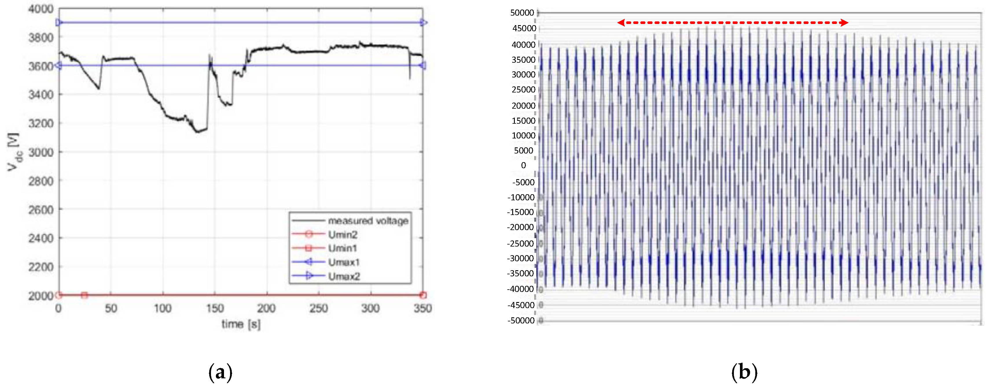
2.6.1. Overvoltage (OvG)

When the system voltage increments and exceeds the higher limit of the designed nominal rate, it is known as an overvoltage situation. This phenomenon is in the range of a 10–20% increase in rms voltage less with a duration longer than 1 min [96]. However, it should be noted that the maximum allowed overvoltage in ERPS is 20%. Based on [99], more than 16% of malfunctions in electric power systems are originated from overvoltage. However, the time/location-varying traction load in ERPS has made it more prone to accept such a phenomenon. Figure 18a illustrates the overvoltage situation during the braking of trains in Metro de Medellin. Various influencing factors can lead to overvoltage occurrence in ERPS as [6,12,115,116,117,118,119]:
  • Voltage increase in the OCS in the case of regenerative braking and lack of consumer trains in the network.
  • The interlinkage of system harmonics and pantograph impedance and created resonances.
  • System instabilities.
  • Oscillations happening in the onboard controllers.
  • Automatic passing of neutral zones.
  • Impedance unconformity at the inverter and traction motor terminals.
  • Lightening overvoltage.
  • Switching or other atmospheric phenomena.
  • Functioning of split-phase breakers in case of phase changing procedure.
The overvoltage can damage electronic equipment, traction, and compressor motors located in the trains and the insulators. It can also cause malfunction and failure on protection and relays.

2.6.2. Undervoltage (UvG)

When the system voltage decrements and exceeds the lower limit of the designed nominal rate, it is known as undervoltage (UvG) situation. According to IEEE 1159-2019, this phenomenon is in the range of a 10% to 20% decrease in rms voltage less with a duration longer than 1 min. However, it should be noted that the minimum allowed voltage drop or undervoltage situation in ERPS is −33% [1]. Therefore, ERPS can tolerate most of these UvG situations. The analysis of voltage drops in ERPS is important for all rating, design, and planning stages to confirm that even under the worst situation, the voltage at the pantograph satisfies the related standards [120,121,122,123]. In DC ERPS, voltage drops are assigned just by the resistive component of the line, omitting the transient phenomena. On the other hand, the AC ERPS lines are affected not only by the resistive component but also by the inductive voltage drop and the reactive power included in the system. Meanwhile, the type of DC power supply including unilateral, bilateral, single-point parallel, and multi-parallel connections can influence the voltage drops [1]. Figure 18b,c show the voltage drop situation over the distance from TPSS in 25 kV AC and 3 kV DC ERPS, respectively.

2.6.3. Interruption Sustained (InRS)

The decrement of the voltage to less than 10% of the nominal value for a duration of more than one minute is characterized as sustained interruption [96]. Like short interruption, this phenomenon can be caused by some influencing factors like operating of the fuses or circuit breaker, failure, and fault in the line equipment undesirable tripping of protective devices and relays [101,109,112,113,114]. In Figure 19 sustained interruption with periods of about 3.5 min, which has been occurred at the substation of Rome subway is demonstrated.

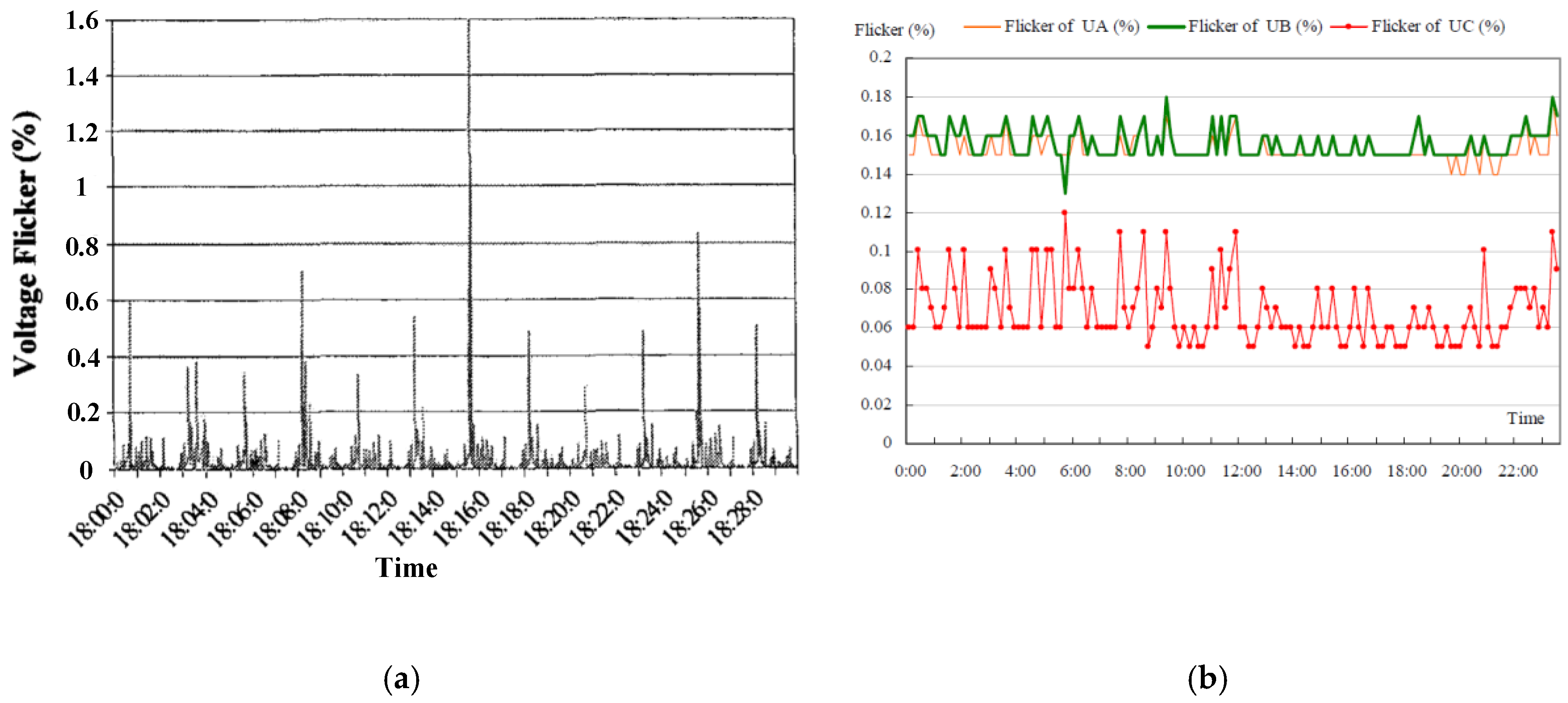
2.7. Voltage Fluctuation (Flicker)

Voltage Fluctuations are characterized as the change in nominal voltage in the range from 0.1 to 7% with frequencies less than 25 Hz. The time-varying specification and abrupt load changes in ERPS can lead to a fast variation of the traction current results in sudden changes of OCS voltage known as voltage flicker. The voltage flicker can have resulted in light flickering, destruct the equipment, unwanted triggering of relays, and protection devices. The currents flowing in ERPS equipment may lead to pulsating forces with high amplitude and which can be potentially harmful to TPSS equipment. Static frequency converters (SFC), the operation of high-power traction motors, and arcing equipment are the main reasons for flicker occurrence [41,124,125,126]. Figure 20 demonstrates the examples of measured short and long duration voltage flicker in ERPS TPSS.

2.8. Waveform Distortion

Waveform distortions are characterized as a steady-state deflection from an ideal fundamental power frequency sinusoidal. According to IEEE 1159-2019, there are five different forms of waveform distortion as harmonics, inter-harmonics, DC offset, notch, and noise. Due to the importance of the harmonic issue in ERPS, we classified and discussed the first two forms separately in harmonic sections.

2.8.1. DC offset

The existence of a dc component in voltage or current in the AC side is characterized as dc offset. In ERPS, the most popular time to occurrence of this phenomenon is controlling 4QCs with indirect current control methods [127,128]. Meanwhile, in the six-step mode control of permanent magnet machines, the difference between the positive and negative half-cycle length can lead to this phenomenon on the AC side [129]. DC offset can cause DC magnetization of magnetic equipment, saturate the transformers, enhance heating problems, stressing of insulation. It can also impact the stability of 4QCs.

2.8.2. Notch

The notch is a kind of voltage disturbance which can be occurred mostly by power electronics devices. Technically, it can be generated by the synchronous transition of two semiconductors persisting on the equal dc output terminal for a short time period, when two out of three of the ac inputs are short-circuited. This can be found especially in voltage source converters controlling by SVM modulation technique which drives traction motors. Meanwhile, this phenomenon can be originated in 4QC drives [3,71,111]. Based on its specification, this phenomenon can be found in both transient and oscillation forms. In addition, due to the periodic situation and frequency oscillation features it can be classified as harmonic distortions. However, implementing high capacitors or batteries can mitigate this phenomenon.

2.8.3. Noise

According to IEEE 1159-2019, noise is characterized as an undesirable electric signal with contents lower than 200 kHz which can be imposed on the voltage/current of conductors [96]. In ERPS, it can be occurred by power electronic devices, control circuits, arcing equipment, and traction locomotives with onboard rectifiers. Meanwhile, impulsive noise and radio frequency (RF) noises have been addressed in some papers [100,130,131,132] as electromagnetic transients caused by the sliding contact between the OCS and the pantograph. The common amplitude of the noise is lower than 0.01 p.u of the voltage magnitude. The communication and signaling systems in ERPS are the most vulnerable parts which are at risk and damage. Utilizing filters and isolation systems, this phenomenon can be mitigated. Due to the high potential of ERPS associated with electromagnetic noises, this phenomenon has been covered and categorized in the conductive electromagnetic interference group.

2.9. Electromagnetic Interference (EMI)

Electromagnetic interference (EMI) is characterized as a phenomenon in which an electromagnetic field (EF) interposes with another, cause to the contortion of both fields. In other words, electromagnetic coupling between a source of interference and a general sufferer system is demonstrated whenever an interlinkage happens between the EF produced by the source and the sufferer system. As a consequence, initiating a transfer of energy between them unfavorably modifies the physical features and performance of the system. EMI and electromagnetic compatibility (EMC) issues play a significant role in the generic performance of the ERPS and signaling systems. The EMI disturbances in ERPS can be manifested by formations of current/voltage, electric/magnetic field coupling and they can be classified into the four types of conduct, inducted, electrostatic, and radiated [1,131,132,133,134,135,136,137,138,139,140,141,142,143,144,145]. The different impacts of EMI between ERPS, infrastructure, and circumambient environment are demonstrated in Figure 21. These EMIs are known as
  • The induced interference voltage because of the inductive/capacitive coupling of three-phase ac power grid transmission lines nearby to the OCS and TPSS.
  • The induced interference voltage by inductive/capacitive coupling of OCS conductors.
  • The conducted interference between rails and signaling systems/track circuits.
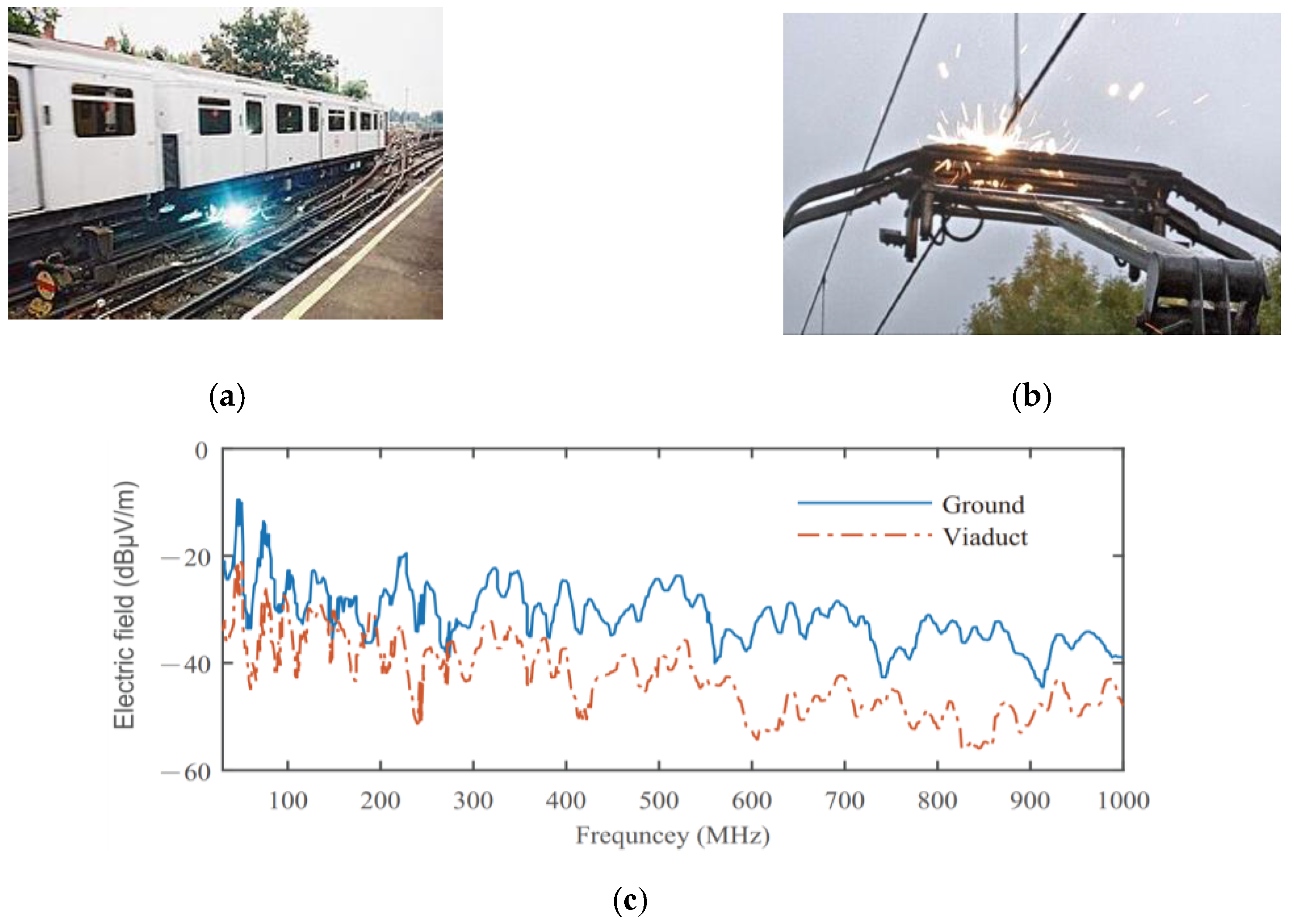
  • The inducted/radiated interference originated by pantograph arcing.

2.9.1. Conducted EMI

Conducted EMI (CEMI) phenomenon occurs when a source and sufferer system share one or more conductors. CEMI can be produced by injection of distorted current or harmonics into the power lines from devices with nonlinear features, or by transient overvoltage originated by switching and atmospheric phenomena [1]. In most ERPS, the running rail conductors are utilized simultaneously as a return circuit and as the conductors for locomotive detection and signaling systems. In this situation, the trains and TPSSs which are the source of harmonic currents can interfere with the signaling system and disrupt the signal of track circuits [1]. The frequency analysis and separation for power systems and signaling systems together with designing frequency filters are the main procedures to mitigate this phenomenon. The earth current or known as the stray current is the other type of foremost conductive coupling that returns currents flow through the earth and re-enter to the rails nearby the TPSS especially in DC ERPS. The high amount of currents injected into the soil can lead to electrochemical corrosion in metal devices buried in the earth. Meanwhile, it can result in high rail to earth or touch voltage [103,131,132,133,134,135,136]. Figure 22a shows a simple diagram of stray current phenomena in DC ERPS. The other form of conducted EMI mentioned in the literature are emissions related to the PWM converters which drive the train’s induction motors [137]. They can be stimulated and generate RF noises. Figure 22b shows an example of measured CEMI in PWM 4QC with power factor correction (PFC) unit.

2.9.2. Inducted EMI

Inductive EMI (IEMI) happens when the magnetic flux is related to the source current interface with a secondary system. ERPS’s lines especially AC types are known as a source of such EMI phenomenon since they can induce the electromotive force (emf) on the close paralleled conductors.
This longitudinal emf and the induced voltage is one of IEMI impacts. The other type is related to physical positioning, cause transverse emf to generate considerable audio frequency noise in communication circuits and power controlling cable networks [131,132,133,134,135,136,137,138,139,140,141,142]. The measured induced voltages on a conductor parallel to ERPS for both 1 × 25 kV and 2 × 25 kV are shown in Figure 23.

2.9.3. Electrostatic/Capacitance EMI

Electrostatic EMI (EEMI) can be caused by the production of electrostatic electric fields (EF) and happens when an EF source (primary system) has a considerable parasitic capacitance against the victim circuit (secondary system), leading to undesirable interference and induced voltage on the secondary system [1]. EEMI is executed when the railway lines are close to the interfering OCS lines (inducing EF source) and the conductors in the line (rails, signaling and telecommunication cables, metal objects) receiving interference. The noise generated by EEMI becomes more critical in the case of a high voltage supply. EEMI has been reported mostly during the regenerative braking of trains in field test measurements with frequencies ranged 8–20 kHz and the maximum transient rail current amount of 10 A [131,132]. It can be categorized in static type, where the conductors of a system with high-voltage make a potential divider toward the capacitors to earth or other metal objects, and dynamic type, where a sudden change in voltage or inherent track admittance like charging and discharging of capacitors or switching semiconductors may cause CdV/dt currents [131,132]. The diagrams of both static and dynamic EEMI are displayed in Figure 24 marking capacitor coupling between wires, ground, and metal subjects closed.

2.9.4. Radiated EMI

One of the foremost common phenomena in ERPS especially in HSR is radiated EMI (REMI) known also as arcing. The interlinkage between the pantograph and contact wire or between the train’s brushes and the third or fourth rail in ERPS and neutral intersection points are the main influencing factors and environments in creating REMI. To put it another way, loss of mechanical touch between a train and supplying wires because of excessive shaking and disturbances at ERPS tracks, the electric arc can occur. Even though the duration of this phenomenon is so short, it is highly nonlinear features lead to distorted currents with RF spectra that makes radiated emissions. The arcing issue can distort voltages and currents of ERPS and produce different kinds of transient problems [131,132,133,134,135,136,137,138,139,140,141,142,143,144,145]. Meanwhile, they can create DC components in AC points which may breakdown of dielectrics. However, the foremost issue caused by REMI is an intervention in the wireless or radio-based telecommunication systems, traction power, and signaling system. Various factors like train speed, absorbed current, inductance feature of OCS, network power factor, etc., can impact the arcing phenomenon. Figure 25a,b show examples of pantograph and brush-based arcing phenomenon in ERS.
The impact of arc in ERPS can be either as radiated or inducted. The radiated EMI type which is discussed in this section is related to the high-frequency part of the pantograph current transient. The inducted type which is related to the low-frequency part of the pantograph current transient is discussed in OsT section. Figure 25c illustrates the measured radiated electric field emission by the pantograph-catenary interaction in the two train positions (viaduct and ground) at 10 m position. As it is obvious in the figure, the frequency band of REMI, in this case, is in the range of 30 MHz to 1 GHz. To have a comprehensive review and appropriate categorization of all mentioned phenomena, the PQ phenomena organized chart is presented in Figure 26. This figure illustrates the overview of the main PQ phenomena together with their different types in ERPS.

3. Investigation of PQ Phenomena Occurrence Based on ERPS Type

Railway electrification has experienced a significant modification and evolution process over time. A sharp increase in population growth and enhanced demand for high-power and high-speed transport together with historical, geographical, and economic policies and features of the countries, have led to different structures of ERPSs all around the world. Depending on the configuration of each ERPS, PQ characteristics and influencing parameters are different. In this section, a brief review of various ERPSs configurations together with the classified reported PQ phenomena in literature based on supplying system type are presented. As mentioned, at the beginning of the ERPS the transformer-based TPSS were prevalent and popular. They were based on the DC supplying system which feeds DC motors directly. The TPSSs in such an ERPS is resourced with the three-phase multiple pulse rectifiers to cover the locomotive’s energy. They lead to a wide spectrum of harmonics. However, in addition to the harmonic problems, voltage fluctuations, voltage imbalance, voltage drops, and other transient events are reported in different DC TPSS around the world. Meanwhile, the brush-based arcs and the EMI based problems due to the stray currents are the other issues of DC ERPS. Inventing advanced PE-based DC TPSS and taking benefits of bidirectional switches, the DC voltage regulation, allowing the regenerative braking energy harvesting of trains, reduction of voltage drop and voltage fluctuation has occurred. With the growing developments of power technologies and electrical motors, the AC transformer-based TPSS were appeared and got popular. The 1 × 25 kV simple and back feeder based structures are initial configurations have been adopted. The main problem of these systems is voltage and current imbalance due to the single-phase feeding systems. Furthermore, the LPF, harmonics, transient problems, and EMI issues, and telecommunication interfaces regarding the return currents are other forms of PQ indices that have been reported in the literature. To decrease the return current of rail and mitigate EMI issues, the booster transformer (BT) based 1 × 25 kV ERPS was presented. However, the large arcing and voltage drops in BT sections could cause essential damage to the OCS. Further, the BT sections reduce the operating speed of trains. Motivated by these problems, the autotransformer based 2 × 25 kV ERPS has been employed. Reducing inductive and telecommunication interfaces, voltage drops, and arcing problems are the foremost features of these systems. Nonetheless, LFO and HI issues regarding the high-speed 4QC based locomotives and impedance interplay among the system and trains are the fundamental obstacles of these ERPS. To decrease the arcing problems and enhance the functioning speed of trains close the TPSSs the specialists provided a new ERPS topology with a lower number of neutral sections and insulating areas. They are known as co-phase system. Disregarding the converter performance in the co-phase ERPS configuration, the PQ issues are like other traditional ERPS except arcing and related problems which have been reduced. During the development of AC industrial frequency-based ERPS, several countries like Germany, Norway, Sweden, Austria, and Switzerland employed the 16.67 Hz ERPS using RFC. The main critical issues of such an ERPS are stability and transient problems owing to the synchronously coupled motor and generators. Furthermore, the modern kind of frequency converter termed the static frequency converter (SFC) comprises high-frequency harmonics and HR and HI phenomena. In addition, a wide range of perturbation among SFC and RFC manifest during their parallel functioning. However, as a consequence of the PE-based equipment, SFC can mitigate the system imbalance, control power factor, and regulate voltage.
With the rapid developments of power electronics and high-voltage switches, a new ERPS structure called advanced co-phase system is presented. Due to the three-phase to single-phase converter and their capability in controlling output voltage and currents, these types of ERPS can compensate harmonics, imbalance, and PF. Meanwhile, with the elimination of neutral zones, the arcing problems and other related voltage variation can be suppressed. In some cases, the three-phase to single-phase converters are based on the modular multilevel converter either direct (AC/AC) or indirect (AC/DC/AC). The MMC based ERPS is connected directly to the utility grid via the three-phase side of MMC. These systems symmetrically transfer active power from the three-phase grid to the single-phase OCS which leads to compensate NSC and harmonics and improve PF simultaneously. Eliminating bulky traction transformers, integrating of OCS, and removing the neutral sections which lead to obviate the arcing problems and voltage fluctuation and transients are the advantages of mentioned ERPS. To have a quick review and appropriate classification of all mentioned ERPS structures, the related organized chart is provided in Figure 27. This figure illustrates a comprehensive classification of ERPS types based on internal configuration.

4. Discussion and Classification

Choosing the right method to mitigate PQ issues requires comprehensive knowledge and identification of main sources, the characteristics, influencing factors, and occurrence environment. Unlike the power grid, for which numerous standards and resources have been developed, the ERPS suffers from a lack of a comprehensive and all-encompassing resource. As discussed before, by the proliferation and development of ERPSs, different forms of PQ phenomena emerge. Generally speaking, all kinds of ERPS can be categorized according to their internal configuration in two groups, transformer-based and modern power electronic converter based. The first category known as the most popular and predominant system is the preference of experts in the designing stage due to the lower expenditure costs and effortless operation. However, as evaluated in a specific framework, these systems deal with many PQ issues which even may enhance their costs remarkably. Meanwhile, as a perspective view and compatibility evaluation with future smart grid-based ERPS, power flow control in these ERPSs contain many complexities and difficulties.
On the contrary, the second group ERPSs taking advantage of the modern converter have not only admirable performance in terms of power quality but also significant potential to achieve future smart grid-based networks. However, the high cost of PE converters is still a basic weak point for this type which has led them to remain in the theoretical stage for the time being and prevents the developments and implementation of these systems. The overall classification of PQ phenomena based on the sources, ERPS system structure, and the probability of occurrence together with an overview of some main studies which have been carried out in each index are provided in Table 3.

5. Conclusions

Since the start of railway electrification, ERPSs have experienced substantial modifications and developments. This diversity including the types of railway power supply systems, AC or DC-based power supply, the types of converters adopted in trains and TPSS, controlling and drive systems, and the dedicated frequency has led to various power quality issues reported all around the world. Furthermore, the lack of specific standards and encompassing resources dedicated to ERPS has increased the obscurity and complexity of its PQ. In this paper, a comprehensive review of PQ phenomena in terms of characteristics, influencing factors, and occurrence sources in different configurations of ERPSs is proposed and a systematic classification is presented. Meanwhile, a detailed review of the reported PQ phenomena in the literature is classified. Unbalance of system, various types of harmonics, low power factor, different aspects of transients events, and waveform deviations, with EMI are addressed with details as the outstanding indexes. Classifying and assessing of diverse transformer-based and PE modern converter based ERPS exposed that the latter types are more efficient and have good performance regarding the PQ issues. Moreover, due to the suitable power flow capability and possible connection to the weak utility networks, which can mitigate and reduce the PQ issues significantly, the converter based ERPS are realized as an appropriate option for smart grid-based future studies of ERPS.

Author Contributions

In preparation of this paper, H.J.K. did the methodology, data curation, software-based simulations, and writing—original draft, M.B., F.F., and D.Z. did the validation, visualization, and the resources and funding acquisition; S.S.F. did the editing, and supervision; All authors have read and agreed to the published version of the manuscript.

Funding

This research received no external funding.

Conflicts of Interest

The authors declare no conflict of interest.

References

  1. Brenna, M.; Foiadelli, F.; Zaninelli, D. Electrical Railway Transportation Systems; IEEE Press Series on Power Engineering: Hoboken, NJ, USA, 2018. [Google Scholar]
  2. Serrano-Jimenez, D.; Abrahamsson, L.; Castano-Solis, S.; Sanz-Feito, J. Electrical railway power supply systems: Current situation and future trends. Int. J. Elect. Power Energy Syst. 2017, 92, 181–192. [Google Scholar] [CrossRef]
  3. Magro, M.C.; Mariscotti, A.; Pinceti, P. Definition of Power Quality Indices for DC Low Voltage Distribution Networks. In Proceedings of the IEEE Instrumentation and Measurement Technology Conference Proceedings, Sorrento, Italy, 24–27 April 2006; pp. 1885–1888. [Google Scholar]
  4. Popescu, M.; Bitoleanu, A. A Review of the Energy Efficiency Improvement in DC Railway Systems. Energies 2019, 12, 1092. [Google Scholar] [CrossRef] [Green Version]
  5. Kaleybar, H.J.; Kojabadi, H.M.; Brenna, M.; Foiadelli, F.; Fazel, S.S.; Rasi, A. An Inclusive Study and Classification of Harmonic Phenomena in Electric Railway Systems. In Proceedings of the 2019 IEEE International Conference on Environment and Electrical Engineering and 2019 IEEE Industrial and Commercial Power Systems Europe (EEEIC/I&CPS Europe), Genova, Italy, 11–14 June 2019; pp. 1–6. [Google Scholar]
  6. Chmielewski, T.; Oramus, P.; Koska, K. Switching transients in a 2 × 15 kV 16.7 Hz autotransformer railway system. IET Gener. Transm. Distrib. 2018, 12, 235–240. [Google Scholar] [CrossRef]
  7. Mariscotti, A. Uncertainty of the Energy Measurement Function deriving from Distortion Power Terms for a 16.7 Hz Railway. Acta Imeko 2020, 9, 25–31. [Google Scholar] [CrossRef]
  8. Laury, J.; Bollen, M.H.J.; Abrahamsson, L. Transient stability analysis of low frequency railway grids. Comput. Railw. XV Railw. Eng. Des. Oper. 2016, 162, 213–223. [Google Scholar]
  9. Seferi, Y.; Blair, S.M.; Mester, C.; Stewart, B.G. Power Quality Measurement and Active Harmonic Power in 25 kV 50 Hz AC Railway Systems. Energies 2020, 13, 5698. [Google Scholar] [CrossRef]
  10. Morrison, R.E. Power quality issues on AC traction systems. In Proceedings of the Ninth International Conference on Harmonics and Quality of Power, Proceedings (Cat. No.00EX441), Orlando, FL, USA, 1–4 October 2000; Volume 2, pp. 709–714. [Google Scholar]
  11. Kaleybar, H.J.; Kojabadi, H.M.; Brenna, M.; Foiadelli, F.; Fazel, S.S. A two-phase three-wire quasi-Z-source based railway power quality compensator for AC rail networks. In Proceedings of the 2017 IEEE Int. Conf. on Environment and Electrical Engineering and 2017 IEEE Industrial and Commercial Power Systems Europe (EEEIC/I&CPS Europe), Milan, Italy, 6–9 June 2017; pp. 1–6. [Google Scholar]
  12. Mariscotti, A. Results on the Power Quality of French and Italian 2 × 25 kV 50 Hz railways. In Proceedings of the 2012 IEEE International Instrumentation and Measurement Technology Conference Proceedings, Graz, Austria, 13–16 May 2012; pp. 1400–1405. [Google Scholar]
  13. Brenna, M.; Foiadelli, F. Sensitivity Analysis of the Constructive Parameters for the 2 × 25 kV High-Speed Railway Lines Planning. IEEE Trans. Power Deliv. 2010, 25, 1923–1931. [Google Scholar] [CrossRef]
  14. Kaleybar, H.J.; Kojabadi, H.M.; Brenna, M.; Foiadelli, F.; Fazel, S.S. An active railway power quality compensator for 2 × 25 kV high-speed railway lines. In Proceedings of the 2017 IEEE Int. Conf. on Environment and Electrical Engineering and 2017 IEEE Industrial and Commercial Power Systems Europe (EEEIC/I&CPS Europe), Milan, Italy, 6–9 June 2017; pp. 1–6. [Google Scholar]
  15. Sun, Z.; Jiang, X.; Zhu, D.; Zhang, G. A novel active power quality compensator topology for electrified railway. IEEE Trans. Power Electron. 2004, 19, 1036–1042. [Google Scholar] [CrossRef]
  16. Xu, Q.; Ma, F.; He, Z.; Chen, Y.; Guerrero, J.M.; Luo, A.; Li, Y.; Yue, Y. Analysis and Comparison of Modular Railway Power Conditioner for High-Speed Railway Traction System. IEEE Trans. Power Electron. 2017, 32, 6031–6048. [Google Scholar] [CrossRef] [Green Version]
  17. Wang, H.; Liu, Y.; Yan, K.; Fu, Y.; Zhang, C. Analysis of static VAr compensators installed in different positions in electric railways. IET Electr. Syst. Transp. 2015, 5, 129–134. [Google Scholar] [CrossRef]
  18. Kaleybar, H.J.; Brenna, M.; Foiadelli, F.; Fazel, S.S. Regenerative Braking Energy and Power Quality Analysis in 2 × 25 kV High-Speed Railway Lines Operating with 4QC Locomotives. In Proceedings of the 2020 11th Power Electronics, Drive Systems, and Technologies Conference (PEDSTC), Tehran, Iran, 4–6 February 2020; pp. 1–6. [Google Scholar]
  19. He, X.; Shu, Z.; Peng, X.; Zhou, Q.; Zhou, Y.; Zhou, Q.; Gao, S. Advanced Cophase Traction Power Supply System Based on Three-Phase to Single-Phase Converter. IEEE Trans. Power Electron. 2014, 290, 5323–5333. [Google Scholar] [CrossRef]
  20. Xie, B.; Li, Y.; Zhang, Z.; Hu, S.; Zhang, Z.; Luo, L.; Cao, Y.; Zhou, F.; Luo, R.; Long, L. A Compensation System for Cophase High-Speed Electric Railways by Reactive Power Generation of SHC&SAC. IEEE Trans. Ind. Electron. 2018, 65, 2956–2966. [Google Scholar]
  21. He, X.; Peng, J.; Han, P.; Liu, Z.; Gao, S.; Wang, P. A Novel Advanced Traction Power Supply System Based on Modular Multilevel Converter. IEEE Access 2019, 7, 165018–165028. [Google Scholar] [CrossRef]
  22. Ronanki, D.; Williamson, S.S. Modular Multilevel Converters for Transportation Electrification: Challenges and Opportunities. IEEE Trans. Transp. Electrif. 2018, 4, 399–407. [Google Scholar] [CrossRef]
  23. Brenna, M.; Foiadelli, F.; Kaleybar, H.J. The Evolution of Railway Power Supply Systems Toward Smart Microgrids: The concept of the energy hub and integration of distributed energy resources. IEEE Electrif. Mag. 2020, 8, 12–23. [Google Scholar] [CrossRef]
  24. He, Z.; Zheng, Z.; Hu, H. Power quality in high-speed railway systems. Int. J. Rail Transp. 2016, 4, 71–97. [Google Scholar] [CrossRef] [Green Version]
  25. Župan, A.; Teklić, A.T.; Filipović-Grčić, B. Modeling of 25 kV electric railway system for power quality studies. In Proceedings of the Eurocon, Zagreb, Croatia, 1–4 July 2013; pp. 844–849. [Google Scholar]
  26. Mariscotti, A. Direct Measurement of Power Quality Over Railway Networks with Results of a 16.7-Hz Network. IEEE Trans. Instrum. Meas. 2011, 60, 1604–1612. [Google Scholar] [CrossRef]
  27. Mariscotti, A. Characterization of Power Quality transient phenomena of DC railway traction supply. ACTA IMEKO 2012, 1, 26–35. [Google Scholar] [CrossRef] [Green Version]
  28. Brenna, M.; Foiadelli, F.; Zaninelli, D. Electromagnetic Model of High Speed Railway Lines for Power Quality Studies. IEEE Trans. Power Syst. 2010, 25, 1301–1308. [Google Scholar] [CrossRef]
  29. Brenna, M.; Foiadelli, F.; Kaleybar, H.J.; Fazel, S.S. Power Quality Indicators in Electric Railway Systems: A Comprehensive Classification. In Proceedings of the 2019 IEEE Milan PowerTech, Milan, Italy, 23–27 June 2019; pp. 1–6. [Google Scholar]
  30. Kuo, H.-Y.; Chen, T.-H. Rigorous evaluation of the voltage unbalance due to high-speed railway demands. IEEE Trans. Veh. Technol. 1998, 47, 1385–1389. [Google Scholar]
  31. Chen, S.-L.; Li, R.; Hsi, P.-H. Traction system unbalance problem-analysis methodologies. IEEE Trans. Power Deliv. 2004, 19, 1877–1883. [Google Scholar] [CrossRef]
  32. Kaleybar, H.J.; Farshad, S. A comprehensive control strategy of railway power quality compensator for AC traction power supply systems. Turk. J. Electr. Eng. Comput. Sci. 2016, 24, 4582–4603. [Google Scholar] [CrossRef]
  33. Zhang, D.; Zhang, Z.; Wang, W.; Yang, Y. Negative Sequence Current Optimizing Control Based on Railway Static Power Conditioner in V/v Traction Power Supply System. IEEE Trans. Power Electron. 2016, 31, 200–212. [Google Scholar] [CrossRef]
  34. Sutherland, P.E.; Waclawiak, M.; McGranaghan, M.F. System impacts evaluation of a single-phase traction load on a 115-kV transmission system. IEEE Trans. Power Deliv. 2006, 21, 837–844. [Google Scholar] [CrossRef]
  35. Kaleybar, H.J.; Kojabadi, H.M.; Fallah, M.; Fazel, S.S.; Chang, L. Impacts of traction transformers on power rating of Railway Power Quality Compensator. In Proceedings of the IEEE 8th International Power Electronics and Motion Control Conference (IPEMC-ECCE Asia), Hefei, China, 22–26 May2016; pp. 2229–2236. [Google Scholar]
  36. Gorski, M.; Heising, C.; Staudt, V.; Steimel, A. Single-phase 50-kW, 16.7-Hz railway-grid Lab Representation using a DC-excited slip-ring induction generator. In Proceedings of the Compatibility and Power Electronics, Badajoz, Spain, 20–22 May 2009; pp. 204–209. [Google Scholar]
  37. Huh, J.; Shin, H.; Moon, W.; Kang, B.; Kim, J. Study on Voltage Unbalance Improvement Using SFCL in Power Feed Network with Electric Railway System. IEEE Trans. Appl. Supercond. 2013, 23, 3601004. [Google Scholar]
  38. IEEE. IEEE Standard Test Procedure for Polyphase Induction Motors and Generators. In IEEE Standard 112; IEEE: New York, NY, USA, 2004. [Google Scholar]
  39. IEC Standard Rotating Electrical Machines-Part26: Effects of Unbalanced Voltages on the Performance of Three-Phase Cage Induction Motors, IEC Standard 60034-26. 2006. Available online: https://webstore.iec.ch/publication/129 (accessed on 17 December 2020).
  40. Motors and Generators; ANSI/NEMA Standard MG1; National Electrical Manufacturers Association: Washington, DC, USA, 2003.
  41. Yu-Quan, L.; Guo-Pei, W.; Huang-Sheng, H.; Li, W. Research for the effects of high-speed electrified railway traction load on power quality. In Proceedings of the 4th International Conference on Electric Utility Deregulation and Restructuring and Power Technologies (DRPT), Weihai, China, 6–9 July 2011; pp. 569–573. [Google Scholar]
  42. Wang, J.; Zhang, M.; Li, S.; Zhou, T.; Du, H. Passive filter design with considering characteristic harmonics and harmonic resonance of electrified railway. In Proceedings of the 8th International Conference on Mechanical and Intelligent Manufacturing Technologies (ICMIMT), Cape Town, South Africa, 3–6 February 2017; pp. 174–178. [Google Scholar]
  43. Lee, H.; Lee, C.; Jang, G.; Kwon, S.-H. Harmonic analysis of the Korean high-speed railway using the eight-port representation model. IEEE Trans. Power Deliv. 2006, 21, 979–986. [Google Scholar] [CrossRef]
  44. Gao, S.; Li, X.; Ma, X.; Hu, H.; He, Z.; Yang, J. Measurement-based compartmental modeling of harmonic sources in traction power-supply system. IEEE Trans. Power Deliv. 2017, 32, 900–909. [Google Scholar] [CrossRef]
  45. Tan, P.-C.; Morrison, R.E.; Holmes, D.G. Voltage form factor control and reactive power compensation in a 25-kV electrified railway system using a shunt active filter based on voltage detection. IEEE Trans. Ind. Appl. 2003, 39, 575–581. [Google Scholar]
  46. Tan, P.-C.; Loh, P.C.; Holmes, D.G. A robust multilevel hybrid compensation system for 25-kV electrified railway applications. IEEE Trans. Power Electron. 2004, 19, 1043–1052. [Google Scholar] [CrossRef]
  47. Kaleybar, H.J.; Farshad, S.; Asadi, M.; Jalilian, A. Multifunctional control strategy of Half-Bridge based Railway Power Quality Conditioner for Traction System. In Proceedings of the 2013 13th International Conference on Environment and Electrical Engineering (EEEIC), Wroclaw, Poland, 1–3 November 2013; pp. 207–212. [Google Scholar]
  48. Ying-Tung, H.; Lin, K.-C. Measurement and characterization of harmonics on the Taipei MRT DC system. IEEE Trans. Ind. Appl. 2004, 40, 1700–1704. [Google Scholar]
  49. Skarpetowski, G.; Zajac, W.; Czuchra, W. Analytical Calculation of Supply Current Harmonics Generated by Train Unit. In Proceedings of the 12th International Power Electronics and Motion Control Conference, Portoroz, Slovenia, 30 August–1 September 2006; pp. 1378–1384. [Google Scholar]
  50. Ogunsola, A.; Mariscotti, A.; Sandrolini, L. Measurement of AC side harmonics of a DC metro railway. In Proceedings of the 2012 Electrical Systems for Aircraft, Railway and Ship Propulsion, Bologna, Italy, 16–18 October 2012; pp. 1–5. [Google Scholar]
  51. Terciyanli, A.; Acik, A.; Cetin, A.; Ermis, M.; Cadirci, I.; Ermis, C.; Demirci, T.; Bilgin, H.F. Power Quality Solutions for Light Rail Public Transportation Systems Fed by Medium-Voltage Underground Cables. IEEE Trans. Ind. Appl. 2012, 48, 1017–1029. [Google Scholar] [CrossRef]
  52. Caramia, P.; Morrone, M.; Varilone, P.; Verde, P. Interaction between supply system and EMU loco in 15 kV-16 2/3 hz AC traction systems. In Proceedings of the Power Engineering Society Summer Meeting. Conference Proceedings (Cat. No.01CH37262), Vancouver, BC, Canada, 15–19 July 2001; Volume 1, pp. 198–203. [Google Scholar]
  53. Caramia, P.; Carpinelli, G.; Varilone, P.; Verde, P.; Gallo, D.; Langella, R.; Testa, A. High speed AC locomotives: Harmonic and interharmonic analysis at a vehicle test room. In Proceedings of the Ninth International Conference on Harmonics and Quality of Power. Proceedings (Cat. No.00EX441), Orlando, FL, USA, 1–4 October 2000; Volume 1, pp. 347–353. [Google Scholar]
  54. Qiujiang, L.; Mingli, W.; Junqi, Z.; Kejian, S.; Liran, W. Resonant frequency identification based on harmonic injection measuring method for traction power supply systems. IET Power Electron. 2018, 11, 585–592. [Google Scholar] [CrossRef]
  55. Spangenberg, U. Variable frequency drive harmonics and interharmonics exciting axle torsional vibration resulting in railway wheel polygonization. Veh. Syst. Dyn. 2020, 58, 404–424. [Google Scholar] [CrossRef]
  56. Laury, J.; Abrahamsson, L.; Bollen, M.H. A rotary frequency converter model for electromechanical transient studies of 1623 Hz railway systems. Int. J. Electr. Power Energy Syst. 2019, 106, 467–476. [Google Scholar] [CrossRef]
  57. Danielsen, S. Electric Traction Power System Stability: Low-Frequency Interaction between Advanced Rail Vehicles and a Rotary Frequency Converter. Ph.D. Dissertation, Norwegian University of Science and Technology Faculty of Information Technology, Mathematics and Electrical Engineering, Trondheim, Norway, 2010. [Google Scholar]
  58. Laury, J.; Abrahamsson, L.; Bollen, M.H. Transient stability of rotary frequency converter fed low frequency railway grids: The impact of different grid impedances and different converter station configurations. In Proceedings of the ASME. ASME/IEEE Joint Rail Conference, Pittsburgh, PA, USA, 18–21 April 2018. [Google Scholar]
  59. Wang, H.; Mingli, W.; Sun, J. Analysis of low-frequency oscillation in electric railways based on small-signal modeling of vehicle-grid system in dq frame. IEEE Trans. Power Electron. 2015, 30, 5318–5330. [Google Scholar] [CrossRef]
  60. Liu, Z.; Wang, Y.; Liu, S.; Li, Z.; Zhang, H.; Zhang, Z. An Approach to Suppress Low-Frequency Oscillation by Combining Extended State Observer with Model Predictive Control of EMUs Rectifier. IEEE Trans. Power Electron. 2019, 340, 10282–10297. [Google Scholar] [CrossRef]
  61. Liu, Z.; Geng, Z.; Hu, X. An approach to suppress low frequency oscillation in the traction network of high-speed railway using passivity-based control. IEEE Trans. Power Syst. 2018, 33, 3909–3918. [Google Scholar] [CrossRef]
  62. Jiang, K.; Zhang, C.; Ge, X. Low-frequency oscillation analysis of the train-grid system based on an improved forbidden-region criterion. IEEE Trans. Ind. Appl. 2018, 54, 5064–5073. [Google Scholar] [CrossRef]
  63. Quesada, I.; Lazaro, A.; Martinez, C.; Barrado, A.; Sanz, M.; Fernandez, C.; Vazquez, R.; Gonzalez, I. Modulation technique for low frequency harmonic cancellation in auxiliary railway power supplies. IEEE Trans. Ind. Electron. 2011, 58, 3976–3987. [Google Scholar] [CrossRef]
  64. Hu, H.; Tao, H.; Blaabjerg, F.; Wang, X.; He, Z.-Y.; Gao, S. Train–network interactions and stability evaluation in high-speed railways—Part I: Phenomena and modeling. IEEE Trans. Power Electron. 2018, 33, 4627–4642. [Google Scholar] [CrossRef]
  65. Hu, H.; Zhou, Y.; Li, X.; Lei, K. Low-Frequency Oscillation in Electric Railway Depot: A Comprehensive Review. IEEE Trans. Power Electron. 2020, 36, 295–314. [Google Scholar] [CrossRef]
  66. Liu, J.; Yang, Q.; Zheng, T.Q. Harmonic analysis of traction networks based on the CRH380 series EMUs accident. In Proceedings of the 2012 IEEE Transportation Electrification Conference and Expo (ITEC), Dearborn, MI, USA, 18–20 June 2012; pp. 1–6. [Google Scholar]
  67. He, Z.; Hu, H.; Zhang, Y.; Gao, S. Harmonic Resonance Assessment to Traction Power-Supply System Considering Train Model in China High-Speed Railway. IEEE Trans. Power Deliv. 2014, 29, 1735–1743. [Google Scholar] [CrossRef]
  68. Hu, H.; He, Z.; Gao, S. Passive Filter Design for China High-Speed Railway with Considering Harmonic Resonance and Characteristic Harmonics. IEEE Trans. Power Deliv. 2015, 30, 505–514. [Google Scholar] [CrossRef]
  69. Song, W.; Jiao, S.; Li, Y.; Wang, J.; Huang, J. High-frequency harmonic resonance suppression in high-speed railway through single-phase traction converter with LCL filter. IEEE Trans. Transp. Electrif. 2016, 2, 347–356. [Google Scholar] [CrossRef]
  70. Brenna, M.; Foiadelli, F.; Zaninelli, D. New Stability Analysis for Tuning PI Controller of Power Converters in Railway Application. IEEE Trans. Ind. Electron. 2011, 58, 533–543. [Google Scholar] [CrossRef]
  71. Morrison, R.E.; Barlow, M.J. Continuous Overvoltages on A.C. Traction Systems. IEEE Trans. Power Appar. Syst. 1983, PAS-102, 1211–1217. [Google Scholar] [CrossRef]
  72. Lutrakulwattana, B.; Konghirun, M.; Sangswang, A. Harmonic resonance assessment of 1 × 25kV, 50 Hz traction power supply system for suvarnabhumi airport rail link. In Proceedings of the 2015 18th International Conference on Electrical Machines and Systems (ICEMS), Pattaya, Thailand, 25–28 October 2015; pp. 752–755. [Google Scholar]
  73. Maeda, T.; Watanabe, T.; Mechi, A.; Shiota, T.; Iida, K. A hybrid single-phase power active filter for high order harmonics compensation in converter-fed high speed trains. In Proceedings of the Power Conversion Conference—PCC ’97, Nagaoka, Japan, 6 August 1997; Volume 2, pp. 711–717. [Google Scholar]
  74. Morrison, R.E.; Corcoran, J.C.W. Specification of an overvoltage damping filter for the National Railways of Zimbabwe. IEE Proc. B Electr. Power Appl. 1989, 136, 249–256. [Google Scholar] [CrossRef]
  75. Kolar, V.; Palecek, J.; Kocman, S.; Vo, T.T.; Orsag, P.; Stýskala, V.; Hrbac, R. Interference between electric traction supply network and distribution power network-resonance phenomenon. In Proceedings of the 14th International Conference on Harmonics and Quality of Power—ICHQP 2010, Bergamo, Italy, 26–29 September 2010; pp. 1–4. [Google Scholar]
  76. Mehdavizadeh, F.; Farshad, S.; Veysi Raygani, S.; Shahroudi, M.R. Resonance verification of Tehran-Karaj electrical railway. In Proceedings of the First Power Quality Conferance, Tehran, Iran, 14–15 September 2010; pp. 1–6. [Google Scholar]
  77. Heising, C.; Bartelt, R.; Staudt, V.; Steimel, A. Single-phase 50-kW 16.7-Hz four-quadrant line-side converter for railway traction application. In Proceedings of the 13th International Power Electronics and Motion Control Conference, Poznan, Poland, 1–3 September 2008; pp. 521–527. [Google Scholar]
  78. Sainz, L.; Caro, M.; Caro, E. Analytical study of the series resonance in power systems with the Steinmetz circuit. IEEE Trans. Power Deliv. 2009, 24, 2090–2098. [Google Scholar] [CrossRef]
  79. Brenna, M.; Capasso, A.; Falvo, M.C.; Foiadelli, F.; LaMedica, R.; Zaninelli, D. Investigation of resonance phenomena in high speed railway supply systems: Theoretical and experimental analysis. Electr. Power Syst. Res. 2011, 810, 1915–1923. [Google Scholar] [CrossRef]
  80. Hu, H.; Tao, H.; Wang, X.; Blaabjerg, F.; He, Z.; Gao, S. Train–network interactions and stability evaluation in high-speed railways—Part II: Influential factors and verifications. IEEE Trans. Power Electron. 2018, 33, 4643–4659. [Google Scholar] [CrossRef]
  81. Mollerstedt, E.; Bernhardsson, B. Out of control because of harmonics an analysis of the harmonic response of an inverter locomotive. IEEE Control Syst. 2000, 20, 70–81. [Google Scholar]
  82. Brenna, M.; Foiadelli, F. Analysis of the filters installed in the interconnection points between different railway supply systems. IEEE Trans. Smart Grid 2012, 3, 551–558. [Google Scholar] [CrossRef]
  83. Wang, Y.; Wang, X.; Blaabjerg, F.; Chen, Z. Harmonic Instability Assessment Using State-Space Modeling and Participation Analysis in Inverter-Fed Power Systems. IEEE Trans. Ind. Electron. 2017, 64, 806–816. [Google Scholar] [CrossRef]
  84. Pan, P.; Hu, H.; Yang, X.; Blaabjerg, F.; Wang, X.; He, Z. Impedance Measurement of Traction Network and Electric Train for Stability Analysis in High-Speed Railways. IEEE Trans. Power Electron. 2018, 332, 10086–10100. [Google Scholar] [CrossRef]
  85. Tao, H.; Hu, H.; Zhu, X.; Zhou, Y.; He, Z. Harmonic instability analysis and suppression method based on αβ-frame impedance for trains and network interaction system. IEEE Trans. Energy Convers. 2019, 34, 1124–1134. [Google Scholar] [CrossRef]
  86. Zhang, X.; Wang, L.; Dunford, W.; Chen, J.; Liu, Z. Integrated Full-Frequency Impedance Modeling and Stability Analysis of the Train-Network Power Supply System for High-Speed Railways. Energies 2018, 11, 1714. [Google Scholar] [CrossRef] [Green Version]
  87. Mariscotti, A.; Slepicka, D. Analysis of frequency stability of 16.7 Hz railways. In Proceedings of the IEEE International Instrumentation and Measurement Technology Conference, Binjiang, China, 10–12 May 2011; pp. 1–5. [Google Scholar]
  88. Mariscotti, A. Behaviour of Spectral Active Power Terms for the Swiss 15 kV 16.7 Hz Railway System. In Proceedings of the IEEE 10th International Workshop on Applied Measurements for Power Systems (AMPS), Aachen, Germany, 25–27 September 2019; pp. 1–6. [Google Scholar]
  89. Raygani, S.V.; Tahavorgar, A.; Fazel, S.S.; Moaveni, B. Load flow analysis and future development study for an AC electric railway. IET Electr. Syst. Transp. 2012, 2, 139–147. [Google Scholar] [CrossRef]
  90. Morais, V.A.; Afonso, J.L.; Carvalho, A.S.; Martins, A.P. New Reactive Power Compensation Strategies for Railway Infrastructure Capacity Increasing. Energies 2020, 13, 4379. [Google Scholar] [CrossRef]
  91. Hafezi, H.; Faranda, R. Open UPQC series and shunt units cooperation within Smart LV Grid. In Proceedings of the 6th International Conference on Clean Electrical Power (ICCEP), Santa Margherita Ligure, Italy, 27–29 June 2017; pp. 304–310. [Google Scholar]
  92. Hafezi, H.; Faranda, R. Power quality and custom power: Seeking for a common solution in LV distribution network. In Proceedings of the IEEE International Conference on Environment and Electrical Engineering and IEEE Industrial and Commercial Power Systems Europe (EEEIC/I&CPS Europe), Milan, Italy, 6–9 June 2017; pp. 1–6. [Google Scholar]
  93. Hu, S.; Xie, B.; Li, Y.; Gao, X.; Zhang, Z.; Luo, L.; Krause, O.; Cao, Y. A Power Factor-Oriented Railway Power Flow Controller for Power Quality Improvement in Electrical Railway Power System. IEEE Trans. Ind. Electron. 2017, 64, 1167–1177. [Google Scholar] [CrossRef]
  94. Wang, K.; Hu, H.; Zheng, Z.; He, Z.; Chen, L. Study on Power Factor Behavior in High-Speed Railways Considering Train Timetable. IEEE Trans. Transp. Electrif. 2018, 4, 220–231. [Google Scholar] [CrossRef]
  95. Huang, C.-P.; Wu, C.-J.; Peng, S.-K.; Yen, J.-L.; Han, M.-H. Loading characteristics analysis of specially connected transformers using various power factor definitions. IEEE Trans. Power Deliv. 2006, 21, 1406–1413. [Google Scholar] [CrossRef]
  96. IEEE. IEEE Std 1159-2019. IEEE Draft Recommended Practice for Monitoring Electric Power Quality; IEEE: New York, NY, USA, 2009. [Google Scholar]
  97. Bigharaz, M.H.; Hosseinian, S.H.; Afshar, A.; Suratgar, A.A.; Dehcheshmeh, M.A. A comprehensive simulator of AC autotransformer electrified traction system. Int. J. Power Energy Convers. 2019, 10, 129–147. [Google Scholar] [CrossRef]
  98. Theethayi, N.; Thottappillil, R.; Yirdaw, T.; Liu, Y.; Gotschl, T.; Montano, R. Experimental Investigation of Lightning Transients Entering a Swedish Railway Facility. IEEE Trans. Power Deliv. 2007, 22, 354–363. [Google Scholar] [CrossRef]
  99. Asmontas, I.; Gudzius, S.; Markevicius, L.A.; Morkvenas, A.; Ticka, V. The investigation of overvoltage transient processes in railway electric power feeding systems. In Proceedings of the Electric Power Quality and Supply Reliability, Tartu, Estonia, 11–13 June 2012; pp. 1–6. [Google Scholar]
  100. Kharbech, S.; Dayoub, I.; Zwingelstein-Colin, M.; Simon, E.P. Blind Digital Modulation Identification for MIMO Systems in Railway Environments with High-Speed Channels and Impulsive Noise. IEEE Trans. Veh. Technol. 2018, 67, 7370–7379. [Google Scholar] [CrossRef]
  101. Lamedica, R.; Maranzano, G.; Marzinotto, M.; Prudenzi, A. Power quality disturbances in power supply system of the subway of Rome. In Proceedings of the IEEE Power Engineering Society General Meeting, Denver, CO, USA, 6–10 June 2004; Volume 1, pp. 924–929. [Google Scholar]
  102. Mariscotti, A. DC railway line voltage ripple for periodic and aperiodic phenomena. In Proceedings of the International Measurement Conference Imeko, Natal, RN, Brazil, 27–30 September 2011. [Google Scholar]
  103. Crotti, G.; Delle Femine, A.; Gallo, D.; Giordano, D.; Landi, C.; Luiso, M.; Mariscotti, A.; Roccato, P.E. Pantograph-to-OHL Arc: Conducted Effects in DC Railway Supply System. IEEE Trans. Instrum. Meas. 2019, 680, 3861–3870. [Google Scholar] [CrossRef] [Green Version]
  104. Mariscotti, A.; Giordano, D. Experimental Characterization of Pantograph Arcs and Transient Conducted Phenomena in DC Railways. Acta Imeko 2020, 9, 10–17. [Google Scholar] [CrossRef]
  105. Terwiesch, P.; Menth, S.; Schmidt, S. Analysis of transients in electrical railway networks using wavelets. IEEE Trans. Ind. Electron. 1998, 45, 955–959. [Google Scholar] [CrossRef]
  106. Xie, C.; Tennakoon, S.; Langella, R.; Gallo, D.; Testa, A.; Wixon, A. Harmonic impedance measurement of 25 kV single phase AC supply systems. In Proceedings of the Ninth International Conference on Harmonics and Quality of Power. Proceedings (Cat. No.00EX441), Orlando, FL, USA, 1–4 October 2000; Volume 1, pp. 214–219. [Google Scholar]
  107. Kaleybar, H.J.; Brenna, M.; Foiadelli, F. Dual-loop generalized predictive control method for two-phase three-wire railway active power quality controller. Trans. Inst. Meas. Control 2020, in press. [Google Scholar] [CrossRef]
  108. Im, Y.C.; Lee, T.H.; Han, I.S.; Park, C.S.; Kim, K.H.; Shin, M.C. Analysis about the tendencies of power quality indices according to the running states of the electric train. In Proceedings of the Transmission & Distribution Conference & Exposition: Asia and Pacific, Seoul, Korea, 26–30 October 2009; pp. 1–6. [Google Scholar]
  109. Femine, A.D.; Gallo, D.; Landi, C.; Luiso, M. Discussion on DC and AC Power Quality Assessment in Railway Traction Supply Systems. In Proceedings of the IEEE International Instrumentation and Measurement Technology Conference (I2MTC), Auckland, New Zealand, 20–23 May 2019; pp. 1–6. [Google Scholar]
  110. Zhang, S.; He, Z.; Lee, W.; Mai, R. Voltage-Sag-Profiles-Based Fault Location in High-Speed Railway Distribution System. IEEE Trans. Ind. Appl. 2017, 53, 5229–5238. [Google Scholar] [CrossRef]
  111. Yoo, J.H.; Shin, S.K.; Park, J.Y.; Cho, S.H. Advanced railway power quality detecting algorithm using a combined TEO and STFT method. J. Electr. Eng. Technol. 2015, 10, 2442–2447. [Google Scholar] [CrossRef] [Green Version]
  112. Seferi, Y.; Clarkson, P.; Blair, S.M.; Mariscotti, A.; Stewart, B.G. Power Quality Event Analysis in 25 kV 50 Hz AC Railway System Networks. In Proceedings of the IEEE 10th International Workshop on Applied Measurements for Power Systems (AMPS), Aachen, Germany, 25–27 September 2019; pp. 1–6. [Google Scholar]
  113. Zhang, Z.; Zheng, T.Q.; Li, K.; Hao, R.; You, X.; Yang, J. Smart Electric Neutral Section Executer Embedded with Automatic Pantograph Location Technique Based on Voltage and Current Signals. IEEE Trans. Transp. Electrif. 2020, 6, 1355–1367. [Google Scholar] [CrossRef]
  114. Agustoni, A.; Borioli, E.; Brenna, M.; Simioli, G.; Tironi, E.; Ubezio, G. LV DC Networks for Distributed Energy Resources. In Proceedings of the CIGRE Symposium on Power Systems with Dispersed Generation, Athens, Greece, 13–16 April 2005. [Google Scholar]
  115. Zhezhelenko, I.V.; Sayenko, Y.L.; Gorpinich, A.V.; Nesterovych, V.V.; Baranenko, T.K. Analysis of resonant modes in the single-phase industrial AC electrified railway systems. In Proceedings of the 10th International Conference on Electrical Power Quality and Utilisation, Lodz, Poland, 15–17 September 2009; pp. 1–4. [Google Scholar]
  116. Wang, Q.; Lu, J.; Wang, Q.; Duan, J. Transient overvoltage study of auto-passing neutral section in high-speed railway. In Proceedings of the IEEE Transportation Electrification Conference and Expo, Asia-Pacific (ITEC Asia-Pacific), Harbin, China, 7–10 August 2017; pp. 1–5. [Google Scholar]
  117. Suárez, M.A.; González, J.W.; Celis, I. Transient overvoltages in a railway system during braking. In Proceedings of the IEEE/PES Transmission and Distribution Conference and Exposition: Latin America (T&D-LA), Sao Paulo, Brazil, 8–10 November 2010; pp. 204–211. [Google Scholar]
  118. Delfino, F.; Procopio, R.; Rossi, M. Overvoltage protection of light railway transportation systems. In Proceedings of the IEEE Bologna Power Tech Conference Proceedings, Bologna, Italy, 23–26 June 2003; Volume 4, p. 8. [Google Scholar]
  119. Pons, E.; Colella, P.; Rizzoli, R. Overvoltages in DC Urban Light Railway Systems: Statistical Analysis and Possible Causes. In Proceedings of the IEEE International Conference on Environment and Electrical Engineering and 2018 IEEE Industrial and Commercial Power Systems Europe (EEEIC/I&CPS Europe), Palermo, Italy, 12–15 June 2018; pp. 1–6. [Google Scholar]
  120. Pilo, E.; Rouco, L.; Fernandez, A.; Abrahamsson, L. A Monovoltage Equivalent Model of Bi-Voltage Autotransformer-Based Electrical Systems in Railways. IEEE Trans. Power Deliv. 2012, 27, 699–708. [Google Scholar] [CrossRef]
  121. Celli, G.; Pilo, F.; Tennakoon, S.B. Voltage regulation on 25 kV AC railway systems by using thyristor switched capacitor. In Proceedings of the Ninth International Conference on Harmonics and Quality of Power. Proceedings (Cat. No.00EX441), Orlando, FL, USA, 1–4 October 2000; Volume 2, pp. 633–638. [Google Scholar]
  122. Tomita, M.; Fukumoto, Y.; Ishihara, A.; Suzuki, K.; Akasaka, T.; Caron, H.; Kobayashi, Y.; Onji, T.; Herve, C. Train Running Test Transmitted by Superconducting Feeder Cable and Study as an Example of Line in Japan and France. IEEE Trans. Appl. Supercond. 2020, 30, 1–7. [Google Scholar] [CrossRef]
  123. Heising, C.; Oettmeier, M.; Gorski, M.; Staudt, V.; Steimel, A. Implications of resonant circuit adjustment errors to the DC-link voltage in single-phase 16.7-Hz-railway applications. In Proceedings of the Compatibility and Power Electronics, Badajoz, Spain, 20–22 May 2009; pp. 210–216. [Google Scholar]
  124. Kneschke, T. Voltage flicker calculations for single-phase AC railroad electrification systems. In Proceedings of the 2003 IEEE/ASME Joint Railroad Conference, Chicago, IL, USA, 24 April 2003; pp. 161–170. [Google Scholar]
  125. Matta, V.; Kumar, G. Unbalance and voltage fluctuation study on AC traction system. In Proceedings of the 2014 Electric Power Quality and Supply Reliability Conference (PQ), Rakvere, Estonia, 11–13 June 2014; pp. 315–320. [Google Scholar]
  126. Guide, Power Quality Application. In Voltage Disturbances; Standard EN 50160; 2004; Available online: https://www.google.co.jp/url?sa=t&rct=j&q=&esrc=s&source=web&cd=&ved=2ahUKEwiz5YLz-dPtAhUqwYsBHaFjBE4QFjAAegQIAxAC&url=https%3A%2F%2Fcopperalliance.org.uk%2Fuploads%2F2018%2F03%2F542-standard-en-50160-voltage-characteristics-in.pdf&usg=AOvVaw031QxJ_AWz-qyKIaM3lLO- (accessed on 17 December 2020).
  127. He, L.; Xiong, J.; Ouyang, H.; Zhang, P.; Zhang, K. High-Performance Indirect Current Control Scheme for Railway Traction Four-Quadrant Converters. IEEE Trans. Ind. Electron. 2014, 612, 6645–6654. [Google Scholar] [CrossRef]
  128. Choudhury, A.; Pillay, P.; Williamson, S.S. DC-Bus Voltage Balancing Algorithm for Three-Level Neutral-Point-Clamped (NPC) Traction Inverter Drive with Modified Virtual Space Vector. IEEE Trans. Ind. Appl. 2016, 52, 3958–3967. [Google Scholar] [CrossRef]
  129. Liu, J.; Zhang, W.; Xiao, F.; Lian, C.; Gao, S. Six-Step Mode Control of IPMSM for Railway Vehicle Traction Eliminating the DC Offset in Input Current. IEEE Trans. Power Electron. 2019, 34, 8981–8993. [Google Scholar] [CrossRef]
  130. Kawasaki, K. Method to Calculate Fluctuations in the Strength of Radio Noise Emitted from Electric Railway Systems. Q. Rep. RTRI 2009, 50, 158–161. [Google Scholar] [CrossRef]
  131. Hill, R.J. Electric railway traction. Part 7: Electromagnetic interference in traction systems. Power Eng. J. 1997, 11, 259–266. [Google Scholar] [CrossRef]
  132. Hill, R.J. Electric railway traction. Part 6: Electromagnetic compatibility disturbance-sources and equipment susceptibility. Power Eng. J. 1997, 11, 31–39. [Google Scholar] [CrossRef]
  133. Ogunsola, A.; Mariscotti, A. Electromagnetic compatibility in railways. In Analysis and Management; Springer: Berlin/Heidelberg, Germany, 2013. [Google Scholar]
  134. Morant, A.; Wisten, Å.; Galar, D.; Kumar, U.; Niska, S. Railway EMI impact on train operation and environment. In Proceedings of the International Symposium on Electromagnetic Compatibility-EMC EUROPE, Rome, Italy, 17–21 September 2012; pp. 1–7. [Google Scholar]
  135. Ogunsola, A.; Mariscotti, A.; Sandrolini, L. Estimation of Stray Current From a DC-Electrified Railway and Impressed Potential on a Buried Pipe. IEEE Trans. Power Deliv. 2012, 27, 2238–2246. [Google Scholar] [CrossRef]
  136. Tellini, B.; Macucci, M.; Giannetti, R.; Antonacci, G.A. Conducted and radiated interference measurements in the line-pantograph system. IEEE Trans. Instrum. Meas. 2001, 50, 1661–1664. [Google Scholar] [CrossRef]
  137. Mariscotti, A. Design of an EMI filter for static converters with off-line simplified measurements. In Proceedings of the IEEE EUROCON 2009, St.-Petersburg, Russia, 18–23 May 2009; pp. 1493–1497. [Google Scholar]
  138. Charalambous, C.; Charalambous, A.; Demetriou, A.; Lazari, A.L.; Nikolaidis, A.I. Effects of Electromagnetic Interference on Underground Pipelines Caused by the Operation of High Voltage AC Traction Systems: The Impact of Harmonics. IEEE Trans. Power Deliv. 2018, 33, 2664–2672. [Google Scholar] [CrossRef]
  139. Konefal, Z.; Fei, T.; Armstrong, R. AC railway electrification systems—An EMC perspective. IEEE Electromagn. Compat. Mag. 2019, 8, 62–69. [Google Scholar]
  140. Niska, S. Electromagnetic interference: A major source of faults in Swedish railway. Int. J. Perform. Eng. 2009, 5, 187–196. [Google Scholar]
  141. Lu, H.; Zhu, F.; Liu, Q.; Li, X.; Tang, Y.; Qiu, R. Suppression of Cable Overvoltage in a High-Speed Electric Multiple Units System. IEEE Trans. Electromagn. Compat. 2019, 61, 361–371. [Google Scholar] [CrossRef]
  142. Mariscotti, A. Induced Voltage Calculation in Electric Traction Systems: Simplified Methods, Screening Factors, and Accuracy. IEEE Trans. Intell. Transp. Syst. 2011, 12, 201–210. [Google Scholar] [CrossRef]
  143. Midya, S.; Bormann, D.; Schutte, T.; Thottappillil, R. Pantograph Arcing in Electrified Railways—Mechanism and Influence of Various Parameters—Part II: With AC Traction Power Supply. IEEE Trans. Power Deliv. 2009, 24, 1940–1950. [Google Scholar] [CrossRef]
  144. Liu, Y.; Chang, G.W.; Huang, H.M. Mayr’s Equation-Based Model for Pantograph Arc of High-Speed Railway Traction System. IEEE Trans. Power Deliv. 2010, 25, 2025–2027. [Google Scholar] [CrossRef]
  145. Li, M.; Wen, Y.; Sun, X.; Wang, G. Analysis of Propagation Characteristics of Electromagnetic Disturbance from the Off-Line of Pantograph-Catenary in High-Speed Railway Viaducts. Chin. J. Electron. 2020, 29, 966–972. [Google Scholar] [CrossRef]
Figure 1. The measured unbalance ratio in Wuhan–Guangzhou high-speed electrified railway system: (a) Current unbalance factor; (b) Voltage unbalance factor [41].
Energies 13 06662 g001
Figure 2. The harmonic spectrum of the traditional and modern trains. (a) Traditional SS4 locomotives. (b) High-speed modern CRH2 locomotives [24].
Energies 13 06662 g002
Figure 3. The primary-side current of n-pulse AC/DC converters with FFT analysis. (a) 6-pulse (b) 12-pulse (c) 18-pulse (d) 24-pulse.
Energies 13 06662 g003
Figure 4. The overhead catenary voltage and current with low frequency oscillation (LFO) phenomenon [59,60].
Energies 13 06662 g004
Figure 5. Measured various types of LFO phenomena [64].
Energies 13 06662 g005
Figure 6. Distorted pantograph voltage/current under the high-frequency resonance with FFT analysis in China and Italy. (a) JingHu high-speed railways (HSR) [64] (b) Italy HSR [79].
Energies 13 06662 g006
Figure 7. Measured overhead catenary system (OCS) voltage and experiment waveform with harmonic instabilities (HI). (a) Traction power substation (TPSS) voltage in electric railway power systems (ERPS) [64]. (b) Phase-to-phase unstable voltage [83].
Energies 13 06662 g007
Figure 8. Classification of harmonic indexes in ERPS. (a) Organization chart. (b) Occurrence frequency range.
Energies 13 06662 g008
Figure 9. Measured power factor (PF) range for different kinds of modern trains. (a) CRH2A-China [94], (b) TGV-France [12], (c) ETR500-Italy [12].
Energies 13 06662 g009
Figure 10. Measured waveforms during lightning occurrence in 4 position distance of Swedish railway facility [98]. (a) Line-to-neutral voltage (b) Local ground to rail current waveforms.
Energies 13 06662 g010
Figure 11. Measured two types of transient voltage in MV busbar of Rome subway system [101]. (a) Recorded type 1 transient voltage. (b) Recorded type 2 transient voltage.
Energies 13 06662 g011
Figure 12. Measured transient voltage in 3 kV DC Italian ERPS [102]. (a) Caused by sudden generated tractive effort. (b) Caused by passing neutral section and changing supplying TPSS.
Energies 13 06662 g012
Figure 13. Measured transient voltage and currents in 3 kV DC ERPS. (a) Pantograph voltage and ripple index caused by changes in operational conditions [104]. (b) Pantograph voltage and current during oscillatory transients (OsT) caused by sliding/jump effect [103].
Energies 13 06662 g013
Figure 14. Measured inrush current transient in Switzerland BLS Re465 locomotive [105].
Energies 13 06662 g014
Figure 15. Measured voltage dip in Korea. (a) 4-cycle voltage sag signal without a noise [111]; (b) 63% voltage sag recorded in Rome metro line [101].
Energies 13 06662 g015
Figure 16. Measured voltage swell in ERPS. (a) 3 kV DC line in Italy [109]. (b) Korea HSR (G7) [108].
Energies 13 06662 g016
Figure 17. The measured interruption in ERPS. (a) Uncontrolled InR in 25 kV AC ERPS line of Italy [112]; (b) Controlled 10 ms InR with smart electric neutral section executer [113].
Energies 13 06662 g017
Figure 18. The measured overvoltage and under voltage in ERPS. (a) Overvoltage situation during braking of trains in Metro de Medellin without dissipating resistance [117] (b) Voltage drop/undervoltage in 25 kV ERPS [120]. (c) Simulated voltage drop across the Rome–Florence HSR line.
Energies 13 06662 g018
Figure 19. The measured sustained interruption with 3.5 min duration in Rome metro line [101].
Energies 13 06662 g019
Figure 20. Measured voltage flicker in railway substation. (a) Short duration flicker [124]. (b) Long duration flicker in three-phase high-voltage busbar [41].
Energies 13 06662 g020
Figure 21. Electromagnetic interference (EMI) occurrence places in ERPS [134].
Energies 13 06662 g021
Figure 22. Different forms of conducted EMI (CEMI) in ERPS. (a) Simple diagram of stray current phenomena in DC ERPS. (b) Output measured EMI in 4QC without filter (output frequency = 15 Hz) [137].
Energies 13 06662 g022
Figure 23. The induced and touch voltage on a conductor parallel to ERPS track. (a) Induced voltage based on the distance of the conductor [138]. (b) Induced voltage based on frequency for both 1 × 25 kV and 2 × 25 kV ERPSs [139].
Energies 13 06662 g023
Figure 24. The static and dynamic electrostatic (EEMI) in ERPS. (a) Static EEMI. (b) Dynamic EEMI.
Energies 13 06662 g024
Figure 25. Arcing phenomenon and measured radiated emission in ERPS. (a) Pantograph arcing. (b) Brush arcing. (c) The measured electric field emission in the range frequency of 30 MHz to 1 GHz with train positions on ground and viaduct [145].
Energies 13 06662 g025
Figure 26. Classification and organization chart of power quality (PQ) phenomena in ERPS.
Energies 13 06662 g026
Figure 27. Classification and organization chart of different ERPS configuration.
Energies 13 06662 g027
Table 1. Different types of reported harmonic resonance (HR) in the literature.
No.Type of HRFrequency Period (p.u)Location
1Parallel15–20, 45–55, 35–59, 50–64China [66,67,68,69]
2Parallel24–30Korea [43]
3Parallel21–29,39,121,139Italy [28,70]
4Parallel20–60United Kingdom [71]
5Parallel49–51Thailand [72]
6Parallel29–41Japan [73]
7ParallelUp to 63Zimbabwe [74]
8Parallel13–20Czech Republic [75]
9Parallel21,81Iran [76]
10Parallel<25Germany [77]
11Series3–7Spain [78]
12Series64, 72, 80Italy [79]
Table 2. Performance of different traction transformers based on PF definitions in the harmonic presence.
Transformer TypeLoad ConditionPF1PFEPFVPFAOverall
Single-phaseBalancedhighvery lowmediumvery lowvery low
Unbalancedhighvery lowmediumvery low
V/VBalancedlowlowhighlowmedium
Unbalancedmediumlowhighmedium
Y/dBalancedvery highmediumvery highmediumvery high
Unbalancedvery highmediumvery highlow
ScottBalancedmediumvery highlowvery highhigh
Unbalancedlowhighlowvery high
Le-BlancBalancedvery lowhighvery lowhighlow
Unbalancedvery lowvery highvery lowhigh
Table 3. Reported classified PQ indexes in different ERPS.
PhenomenaTypeCauses and SourcesSystem Type & References
UnbalanceVUFsingle-phase power supply, asymmetric faultsAC 1 × 25 kV [30], AC 2 × 25 kV [37,41]
CUFsingle-phase power supply, asymmetric faultsAC 2 × 25 kV [31,41], AC 1 × 25 kV [33], AC 15 kV-16.67 Hz [36]
HarmonicsLOHbackground harmonics, train internal harmonics, DC rectifier substationAC 1 × 25 kV [24,44,45,46,47], AC 2 × 25 kV [42,43], LVDC [29,48,50], MVDC [49,51]
InHAC motors controlled by variable frequency drives, onboard PWM convertersAC 1 × 25 kV [54,55], 2 × 25 kV [53], 15 kV-16.67 Hz [52], MVDC [53]
LFOimpedance mismatch between the railway network and PWM trains, rotary converterAC 1 × 25 kV [59,60,61,62], 2 × 25 kV [64,65]
15 kV-16.67 Hz [56,57,58], MVDC [63]
HRinteraction of current harmonics and internal resonance of LC circuit of OCSAC 1 × 25 kV [71,72,73,74,75], 2 × 25 kV [66,67,68,69,70,76,79], 15 kV-16.67 Hz [77]
HIinteraction between high switching frequency of PWM converters in modern trains and internal resonance of OCS, high-frequency specifications of the closed-loop control system for 4QCAC 1 × 25 kV [85,86], 2 × 25 kV [80,82,84], 15 kV-16.67 Hz [81,87], MVDC [82]
Low Power FactorLPFoverlap commutation angel in conventional rectifier, inductive reactance features of the OCS, supplying sections with different phaseAC 1 × 25 kV [89,90,95], 2 × 25 kV [92,93,94], 15 kV-16.67 Hz [88], MVDC [12], LVDC [12,51]
Transient eventsImTlightening, switching of circuit breakers, abnormal changing in tractive efforts, sliding contact between pantograph and OCS, passing neutral zoneAC 1 × 25 kV [99,100], 2 × 25 kV [97], 15 kV-16.67 Hz [98], MVDC [99,102], LVDC [101,102]
OsTchanging in operational condition and modulation patterns, sliding contact and pantograph jump over OCS, inrush current of locomotive transformer, capacitor bank energizationAC 1 × 25 kV [106,111], 2 × 25 kV [1], 15 kV-16.67 Hz [105], MVDC [103,104], LVDC [103,104]
Short duration rms variationSagfault occurrence, high current absorbed by traction motors, sudden load changes or supplying high-power locomotives, TPSS transformers energization/de-energization, motor blocking caused by the segregation of pantograph and OCS, neutral sections, TPSS equipment triggeringAC 1 × 25 kV [108,111,112], 2 × 25 kV [110], 15 kV-16.67 Hz [105,109], MVDC [109]
SwellAC 1 × 25 kV [108,111,112], 2 × 25 kV [110], 15 kV-16.67 Hz [105,109], MVDC [109]
InRtrain passes NZ, pantograph bounce operating of the circuit breaker, failure, and fault, abruptly disconnection between the contact wire and pantographAC 1 × 25 kV [108,109,112,113], 2 × 25 kV [108,113], 15 kV-16.67 Hz [109], MVDC [109], LVDC [3,114]
Long duration rms variationOvGregenerative braking and lack of consumer trains, resonance, system instabilities, passing of neutral zones, lightning, switching or other atmospheric phenomena, functioning of split-phase breakersAC 1 × 25 kV [99,115], 2 × 25 kV [12,116], 15 kV-16.67 Hz [6], MVDC [117], LVDC [117,118]
UvGType of line (unilateral, bilateral, …), high traffic of line, resonance, system instabilities, passing of neutral zones,AC 1 × 25 kV [122], 2 × 25 kV [120,121], 15 kV-16.67 Hz [123], MVDC [1,122], LVDC [1,117,122]
InRSTrain passes NZ, pantograph bounce operating of the circuit breaker, failure, and fault, abruptly disconnection between the contact wire and pantographAC 1 × 25 kV [108,109,112,113], 2 × 25 kV [108,113], 15 kV-16.67 Hz [109], MVDC [109], LVDC [3,114]
Voltage fluctuation
(Flicker)
FlKtime-varying specification, abrupt load changes in ERPS, static frequency converters, operation of high-power traction motors, arcing equipmentAC 1 × 25 kV [41,108,124,125], 2 × 25 kV [108], 15 kV-16.67 Hz [124], LVDC [124]
Waveform distortionDC offsetindirect current control method of 4QCs, inequality of the positive and negative half-cycle length in six-step mode controlAC 1 × 25 kV [127,129], 2 × 25 kV [127,129], 15 kV-16.67 Hz [127], MVDC [127], LVDC [128]
Notchpower electronics devices, 4QC drives, abruptly disconnection between the contact wire and pantographAC 1 × 25 kV [45,71,111], 2 × 25 kV [18,111],
Noisepower electronic devices, control circuits, arcing equipment and traction locomotives with onboard rectifiers, sliding contact between the OCS and the pantographAC 1 × 25 kV [100,131,132], 2 × 25 kV [100], 15 kV-16.67 Hz [131,132], MVDC [130], LVDC [130,131,132]
Electromagnetic InterferenceCEMIinjection of distorted current or harmonics into the power lines from devices with nonlinear features, transient overvoltage originated by switching and atmospheric phenomena, return current flowing through earthAC 1 × 25 kV [1,134,137], 2 × 25 kV [1,134,137], 15 kV-16.67 Hz [1,137,140], MVDC [1,135,136,145], LVDC [1,135,145]
IEMIInterfacing of magnetic flux related to the source current with a secondary closed system, physical positioning causing transverse emfAC 1 × 25 kV [1,134,138,139,143,144], 2 × 25 kV [1,138,139,142,143,144], 15 kV-16.7 Hz [1,138,140]
EEMIproduction of electrostatic electric fields, capacitive interference between closed conductors and earth, the sudden change in voltage or inherent track admittance causing charging and discharging of capacitors or switching semiconductorsAC 1 × 25 kV [1,133], 2 × 25 kV [1,133], 15 kV-16.7 Hz [1,133]
REMIThe interlinkage between the pantograph and contact wire or between the train’s brushes and the third or fourth rail, neutral intersection pointsAC 1 × 25 kV [1,143], 2 × 25 kV [1,143], 15 kV-16.7 Hz [1], MVDC [103,136,145], LVDC [103,145]
Publisher’s Note: MDPI stays neutral with regard to jurisdictional claims in published maps and institutional affiliations.

