1. Introduction
Nowadays, many applications that use hydraulic or pneumatic drives or even electric drives combined with mechanical transmission systems are being substituted by linear electric actuators in industrial and aerospace applications. These actuators convert electric energy directly into a linear controlled movement with low cost and simple control. They are constituted of a fixed part or stator (primary) and a moving part or mover (secondary), both parts can contain coils, permanent magnets (PM) or bars. There are different kinds of linear electric actuators but linear switched reluctance motors (LSRM) are an attractive option due to their simple construction, robustness, and good fault capability despite their low force/mass ratio [
1,
2]. This disadvantage can be relieved by inserting permanent magnets (PM) in its magnetic structure, giving rise to the linear hybrid reluctance actuators. In some of these actuators, due to the disposition of the permanent magnets, the detent force is negligible [
3]. Unfortunately, in most of these types of machines when the phases are not energized a detent force appears because of the interaction between the permanent magnets and the poles or teeth in which the windings are disposed of. Different techniques have been proposed for the reduction in detent force, the most usual are aside PM skewing and PM length/width adjustment [
4,
5], an asymmetric arrangement of PM, use of semi-closed slots [
6], and utilization of auxiliary teeth or teeth notching [
7]. Some other techniques use specific control strategies [
8], in some cases, a combination of control and structural design (e.g., skewing PM, Halbach array) are employed [
9,
10], and others are based on the shift of the permanent magnets, poles and slots, the slots or poles and the distance between the magnet segments of each pole [
11,
12,
13,
14].
During the work cycle (ascent or horizontal for linear machine), the propulsion force and direction of motion are in the same direction, and during descent, the propulsion force is acting in the direction opposite to that of the motion [
15,
16]. Propulsion force is a key concept for this type of machine, this defines the application in each type of machine configuration, and therefore defines a profile of force (
FX) and displacement (
x) with peaks and minimums of propulsion force, which are necessary to adapt to the different applications [
16]. Regarding the detent force importance, the main constraint of the slotted iron core type in magnet linear motors is the detent force that is caused by the interaction between the permanent magnet (PM) and the slotted iron core. This detent force will generate the pulsations of the propulsion force, and it will deteriorate the smoothness of motion drive, one of the main goals of the design of this type of electrical machine is to minimize this detent force. In general, the amplitude of the detent force is dependent on some major factors, such as pole-arc to a pole-pitch ratio of a magnet, air-gap length, slot opening length, skew of either stator teeth or magnet poles, and other key design factors [
17,
18].
Reluctance machines present good environmental behavior due to their high efficiency and inherent ease of assembly and dismantling [
19]. For these reasons, among others, several studies have focused on new magnetic structures [
20,
21] in order to enhance their force performance [
22] and increase force density by adding permanent magnets, some examples of electrical machines using permanent magnets have been developed recently in many research works [
22,
23,
24,
25,
26,
27]. As an example, linear switched reluctance motors (LSRM) and linear permanent magnet synchronous motors (LPMSMs) have been proposed for propelling a ropeless elevator [
28], for an automotive suspension system [
29], and for a linear generator in direct drive wave-power converter [
30]. Despite their advantages, the permanent magnets linear (PML) motors exhibit some drawbacks: one of them is the presence of a cogging force, which can introduce a disturbance in positioning precision. The cogging force, in PML motors, is caused by two phenomena. The first one arises from the interaction between the PMs and the finite length of the armature core and is often called “end-effect”. It can be minimized by adopting a suitable stator length [
31] or modifying the extremity shape of the shorter part [
32]. On the other hand, the U-core or U-channel air-core permanent magnet linear synchronous motors are widely applied in direct-drive linear motion servo systems, as they could offer significant advantages in terms of high efficiency, high positioning accuracy, rapid dynamic response, simple structure, and long service lifetime [
33,
34,
35,
36].
In this paper, a two-phase double-sided segmented stator, using laminated U cores, with an interior PM mover is proposed. Its main goal is to have high propulsion or thrust force and a low detente force.
The former concept-design of this two-phase linear hybrid reluctance motor comes from the optimized LSRM presented in [
1], from which mover and stator dimensions are kept. That magnetic structure was hybridized by inserting Neodymium Iron Boron NdFeB magnets and was analyzed in [
37].
The proposed two-phase actuator differs from the linear hybrid reluctance motor presented in [
37] in the number of phases and in that the segmented stator is built with magnetically and mechanically decoupled U cores. This fact allows the relative displacement of the lower stator to respect the upper stator for reducing the detent force
After this introduction, the paper is organized as follows. In
Section 2, a description of the proposed actuator is provided. The simulation of the actuator is performed with a 2D finite element analysis in
Section 3. The reduction in the detent force is addressed in
Section 4. A comparative study regarding switched reluctance and linear permanent actuators of the same size is performed in
Section 5. The verification results obtained by 3D finite element analysis and experimental tests are shown in
Section 6. Finally, in
Section 7, conclusions from this research are drawn.
2. Description of the Proposed Actuator
In order to enhance the propulsion force of a conventional two-phase LSRM, a new two-phase double-sided linear hybrid reluctance actuator (PM-LHRM) is proposed.
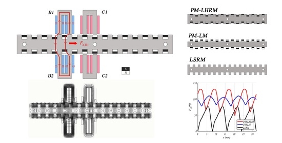
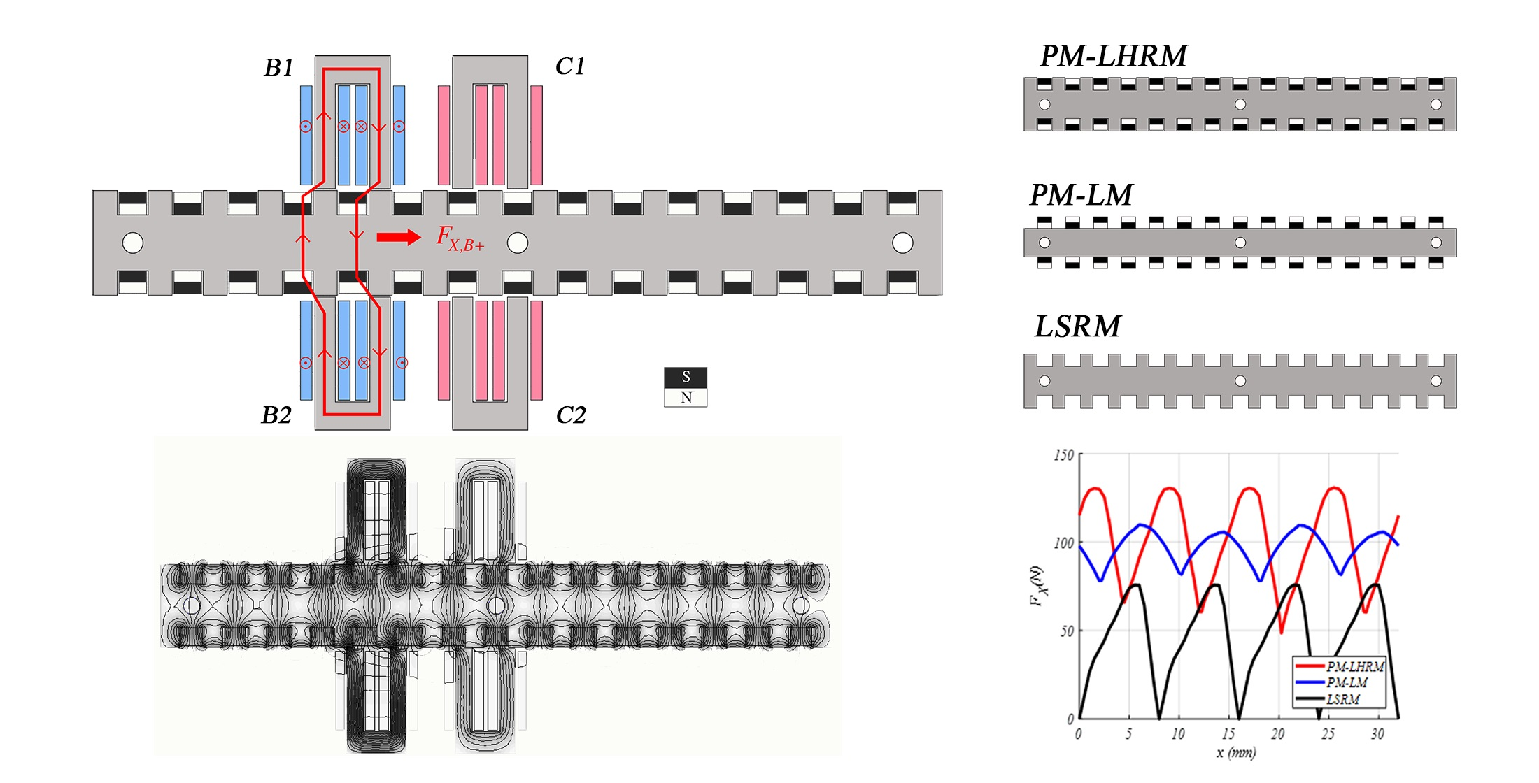
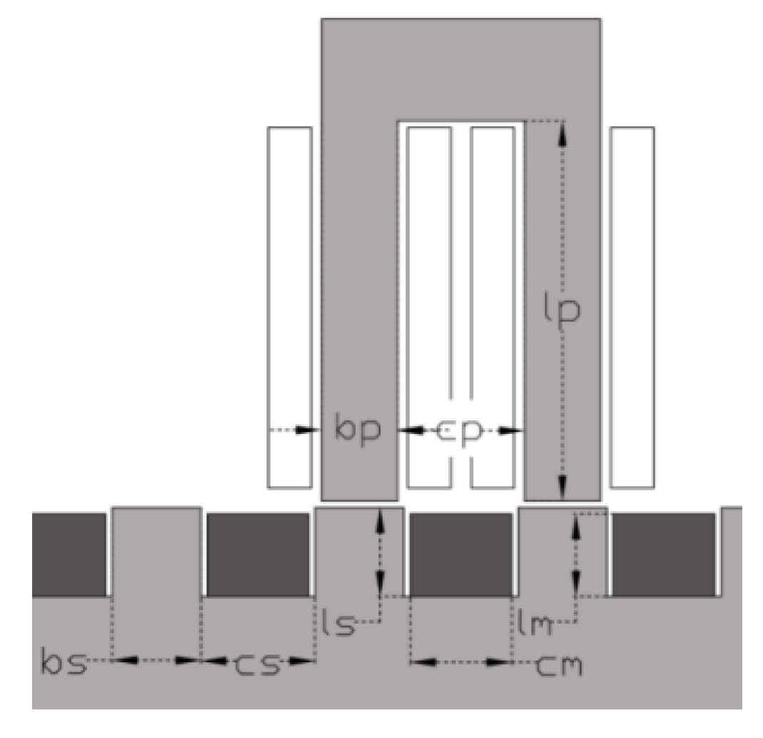
Figure 1 is a drawing of the PM-LHRM arrangement, wherein light grey shows the two symmetrical primary structures that contains the two phases, in blue and red, respectively, for the two phases B and C, whose magnetic circuit is made of two U laminated cores per phase. The secondary, depicted in grey, has disposed of the permanent magnets (NdFeB-N32) (in black/white) between their poles with the direction of magnetization shown in
Figure 1 (
S-N-
S-N-
S … in both sides). Each phase is energized through an H-bridge inverter that allows switching the phase current to a positive value +I to a negative value –I in the period of conduction of the corresponding phase. The goal is to double the total average force of a linear switched reluctance actuator of the same geometry. The actuator is intended for short-time duty cycle (S2) applications with an average total thrust of 100 N at a speed of 0.15 m/s, which not require a very precise positioning such as automatic door opener systems.
The operating principle is shown in
Figure 1, which sketches a field line when exciting phase B with a positive current, called B+, and the resulting propulsion force (
FX,B+) in the right direction (positive). Without PMs in the mover, the structure is a conventional LSRM, in which feeding the same phase B+ the propulsion force is zero at
x = 0 mm, and the same would happen by feeding phase C. The existence of these zero-force positions disables the two-phase LSRM as a propulsion actuator.
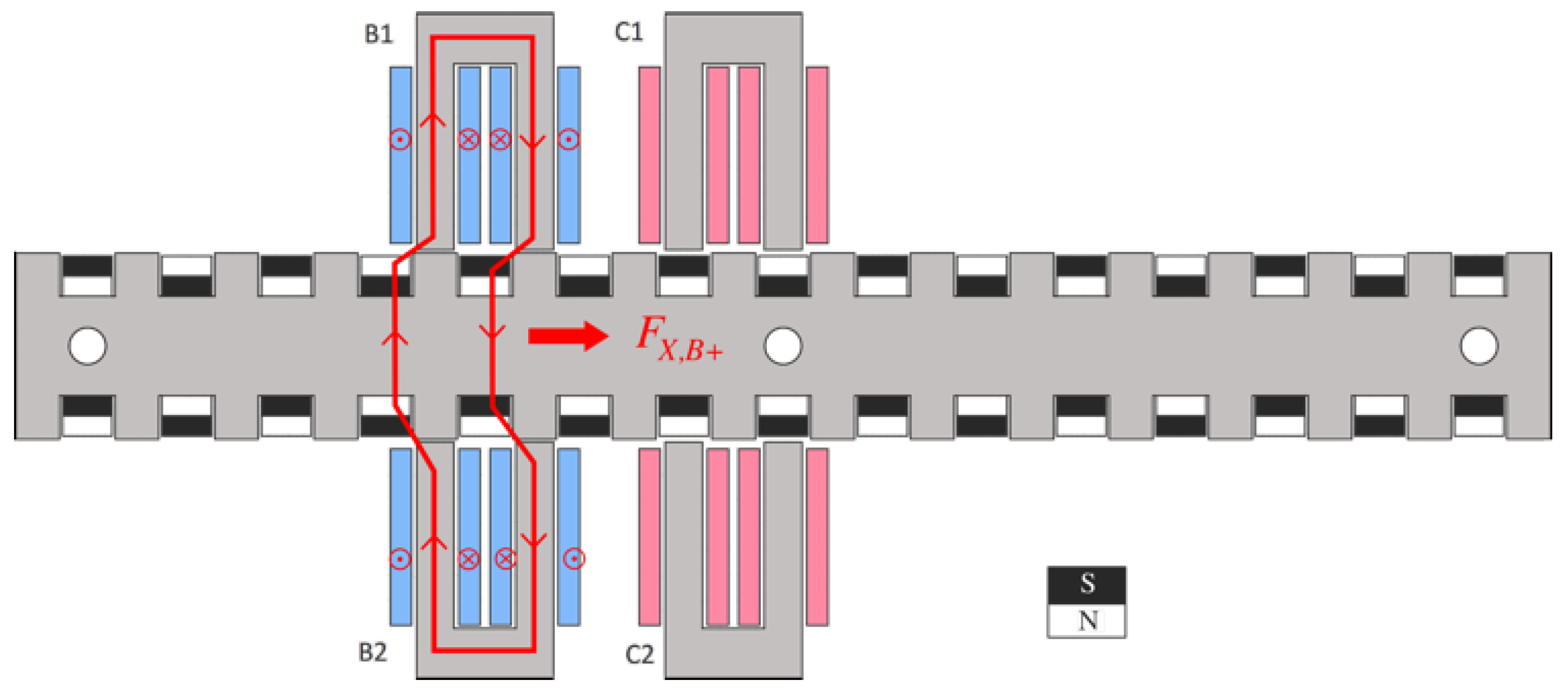
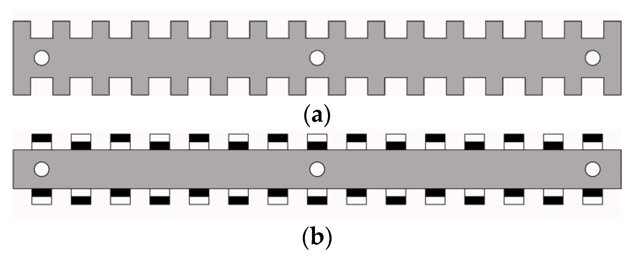
In order to assess the PM-LHRM, it will be compared with a pure reluctance motor, demoted by LSRM (see
Figure 2a), and with a permanent magnet linear motor without iron poles in the mover, denoted by PM-LM (see
Figure 2b). The LSRM and PM-LM actuators have the same stator structure of
Figure 1, but their respective movers are different as shown in
Figure 2.
Some relevant details about the design of the proposed machine are given in the
Appendix A.
3. Simulation of the Actuator
The PM-LHRM, LSRM, and PM-LM actuators were simulated using 2D finite element analysis [
38] and
Matlab, for a current density of 10 A/mm
2. This current density value is chosen because the actuator is conceived for short intermittent duty cycles. It is important to point out that there is only one flux-path per phase, and the phases are magnetically uncoupled, that is, the flux created by coil phase B does not link coil phase C. The simulation model has more than 185k elements and nearly 93k nodes, and a simulation solver precision of 10 nano.
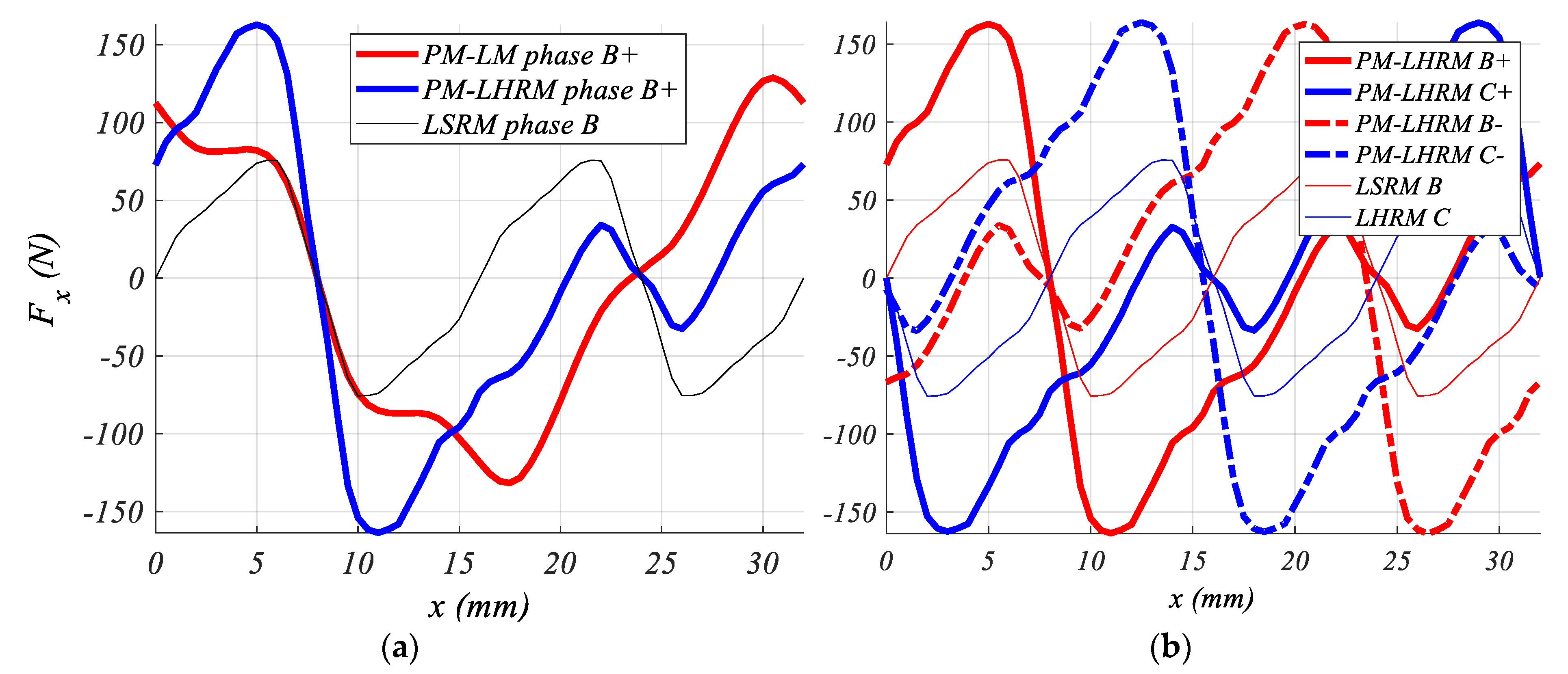
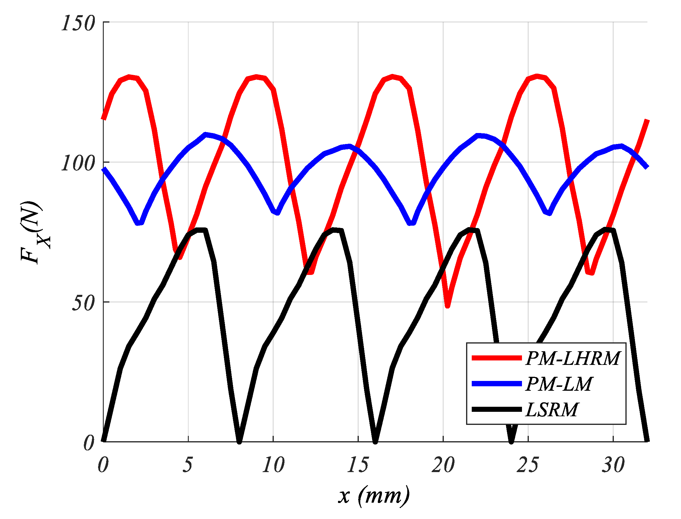
Figure 3a shows the comparison between the force profiles of the three structures, in which it can be seen a prominent force peak (>150 N) for the PM-LHRM, which doubles the force peak (
Fpeak) of the LSRM. Moreover, the force becomes anti-symmetric for the PM-LHRM when the phase-current is inverted, that means zero-force positions can be overlapped when phases are fed with the appropriate sequence (e.g., B+ C+ B- C-), as can be seen in
Figure 3b. Therefore, adding the PMs to the two-phase LSRM magnetic circuit allows the elimination of zero-force positions, which position this PM-LHRM configuration as a good solution for high-density thrust actuators. The relevant values shown in
Figure 3 are
Fpeak = 162.8 N for the PM-LHRM,
Fpeak = 128.8 N for PM-LM,
Fpeak = 75.8 N for LSRM, and the average force values
Fave = 91.4 N,
Fave = 78.1 N,
Fave = 46.6 N, respectively, being the average force values computed over a semi-period.
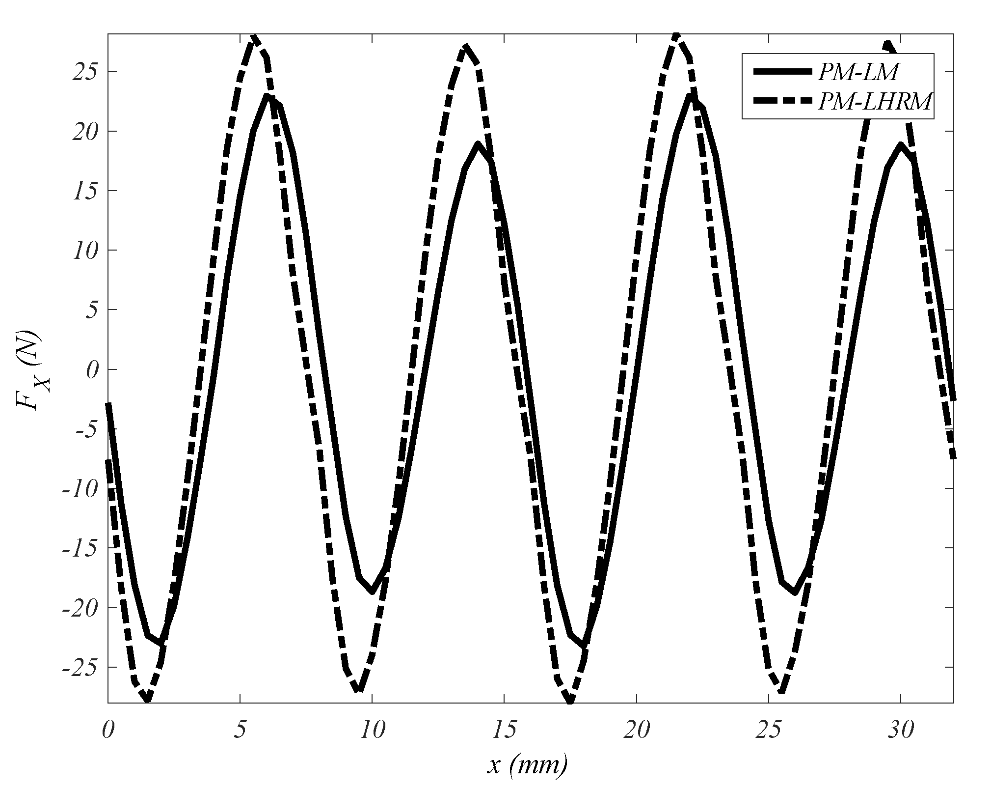
The detent force that appears when currents are zero, due to the presence of PMs, is represented in
Figure 4. The detent force values are 28.2 N of peak, (17.3% of peak force) and a root mean square (
rms) value 18.9 N-rms for the PM-LHRM structure, and 22.9 N of peak (17.8% of peak force) and 14.6 N-rms for PM-LM. These values are far from negligible and therefore they are a significant drawback, despite the better performance of PM-LHRM and PM-LM in respect to the LSRM.
4. Reduction in Detent Force
The PM linear motors and by extension the hybrid magnetic structures exhibit the so-called detent force, which means the existence of a threshold force under which the motor cannot operate. This force is due to the PM flux lines that sew stator and rotor at given positions due to the slotted structures, called “slotting effect”. This causes error in positioning, vibrations, and noise. Reference [
12] classifies linear motors according to
X configuration, where the secondary is longer than primary, and Y configuration, where secondary is shorter than primary. Both configurations suffer the “slotting effect”, additionally
X configuration also has the “end-effect”, which has less relevance than the “slotting effect”, as shown in
Section 6.
After considering the different alternatives exposed in
Section 1 for the reduction in detent force, the option based on the technique of pole shifting [
12] was selected because it was the easiest to implement given the modular arrangement of the proposed actuator built with independent U cores. This was implemented maintaining the U cores of the upper stator—B1 and C1—in the same position (see
Figure 1), and displacing the U cores of the lower stator—B2 and C2—a certain distance, called shift, into the right direction.
To analytically approach the analysis, several methodologies are presented in [
9,
10,
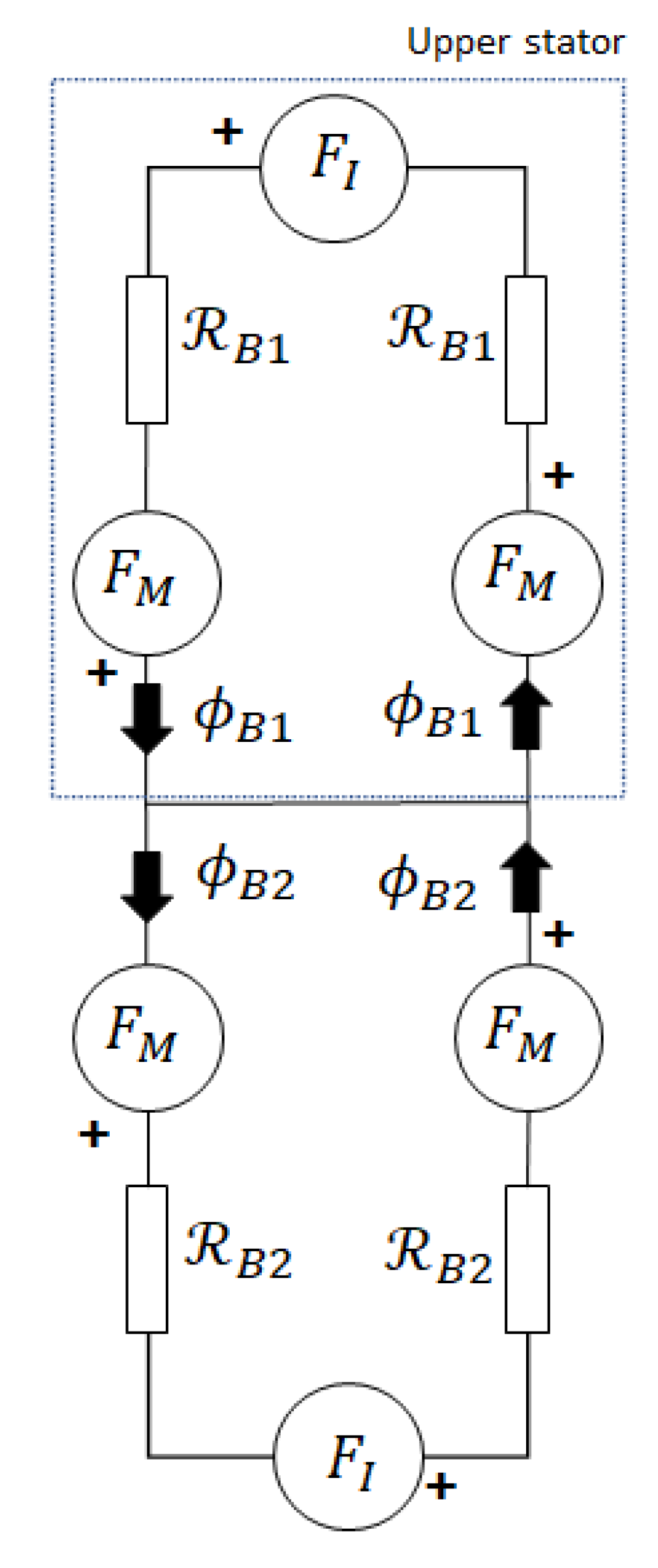
14]. In this case, a simplified magnetic equivalent circuit based on
Figure 1 is proposed (see
Figure 5). In this approach, the iron reluctances are neglected as well as the leakage fluxes. In
Figure 5, FI stands for the phase-coil magneto-motive force (
mmf) and FM for the magnet’s
mmf, being
FM=
HM·
lm. A sinusoidal flux variation is also assumed in respect to position
x, see Equations (1) and (2) for phase B and Equations (3) and (4) for phase C. It is also considered a variable accounting for the displacement
s between the upper and lower phase-stators to reduce the detent force. The numerical values for the variables
Ts,
LW and
Cm are given in the
Appendix Table A1.
The reluctances,
(
x,
s), of each
U core, with regards to the value of
x and
s are obtained in the following Equations (5)–(8):
The reluctance value
corresponds to the unaligned position (see phase C in
Figure 1) and
to the aligned position (see phase B in
Figure 1), these two reluctance values can be obtained analytically by computing and adding the permeance flux-tubes set obtained at the given positions. The detent force (
Fd) is then obtained by Equation (9).
Thus, Fd is minimized regarding the shift variable, s, reaching a minimum value of detent force at s = 4 mm for the given values.
In order to provide an expression involving the phase-current (
I) and the number of turns (
N), it can be obtained by applying the second
Kirchoff law to either of the loops (see
Figure 5), resulting:
The detent force is computed numerically using 2DFEM solver [
39] by using Maxwell stress tensor and analytically by the set of Equations (1)–(9).
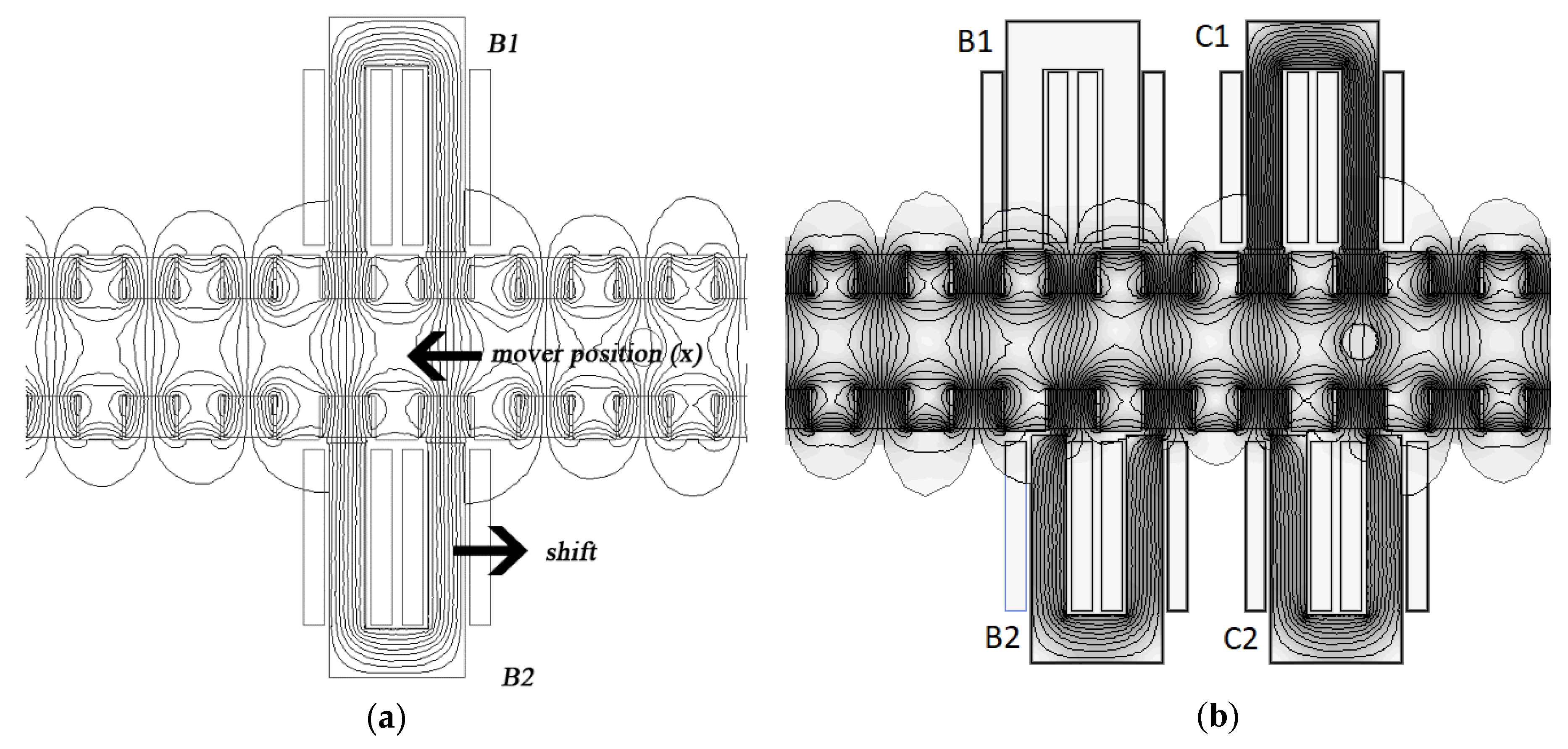
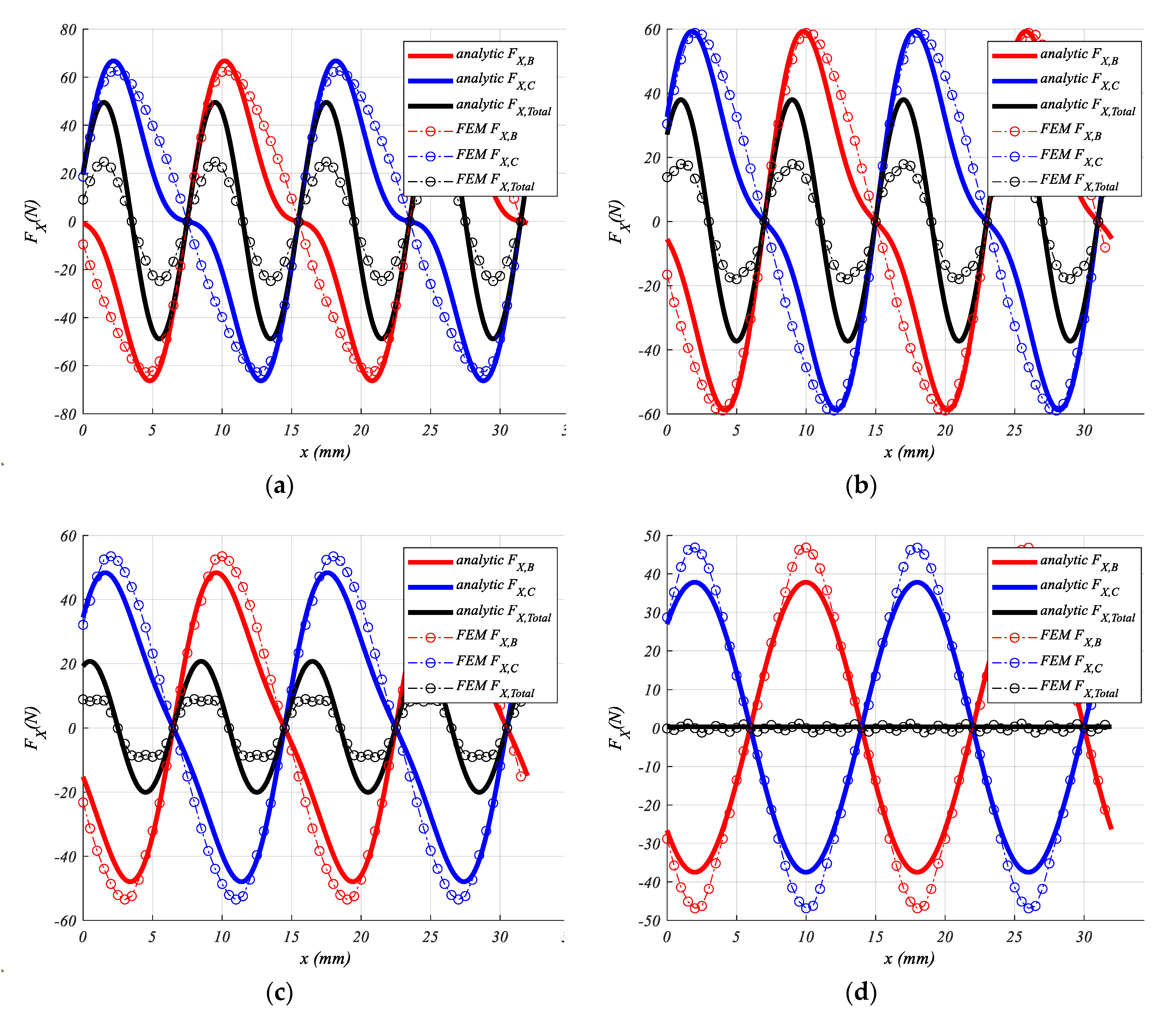
Figure 6a shows the flux line distribution for a given position considering only phase B.
Figure 6b shows the flux distribution of the whole PM-LHRM for a given shift. To assess the goodness of the analytical approach, 2DFEM simulations are computed over a one phase (B), and it is considered the detent force of other phase (C) out of phase (i.e., 180°), regarding to phase B. The detent force comparison of each phase (phase B in red and phase C in blue) and the total force (in black) is depicted in
Figure 7, for both analytical and 2DFEM results. As can be seen, both models match quite well at
s = 4 mm when both, FEM and analytical, predict a minimum detent force. The differences with other shift values are due to the analytical model’s accuracy, few flux tubes are considered, since the goal is not to present an accurate analytical model but rather to give an analytical vision on the effects of the shift displacement on the detent force.
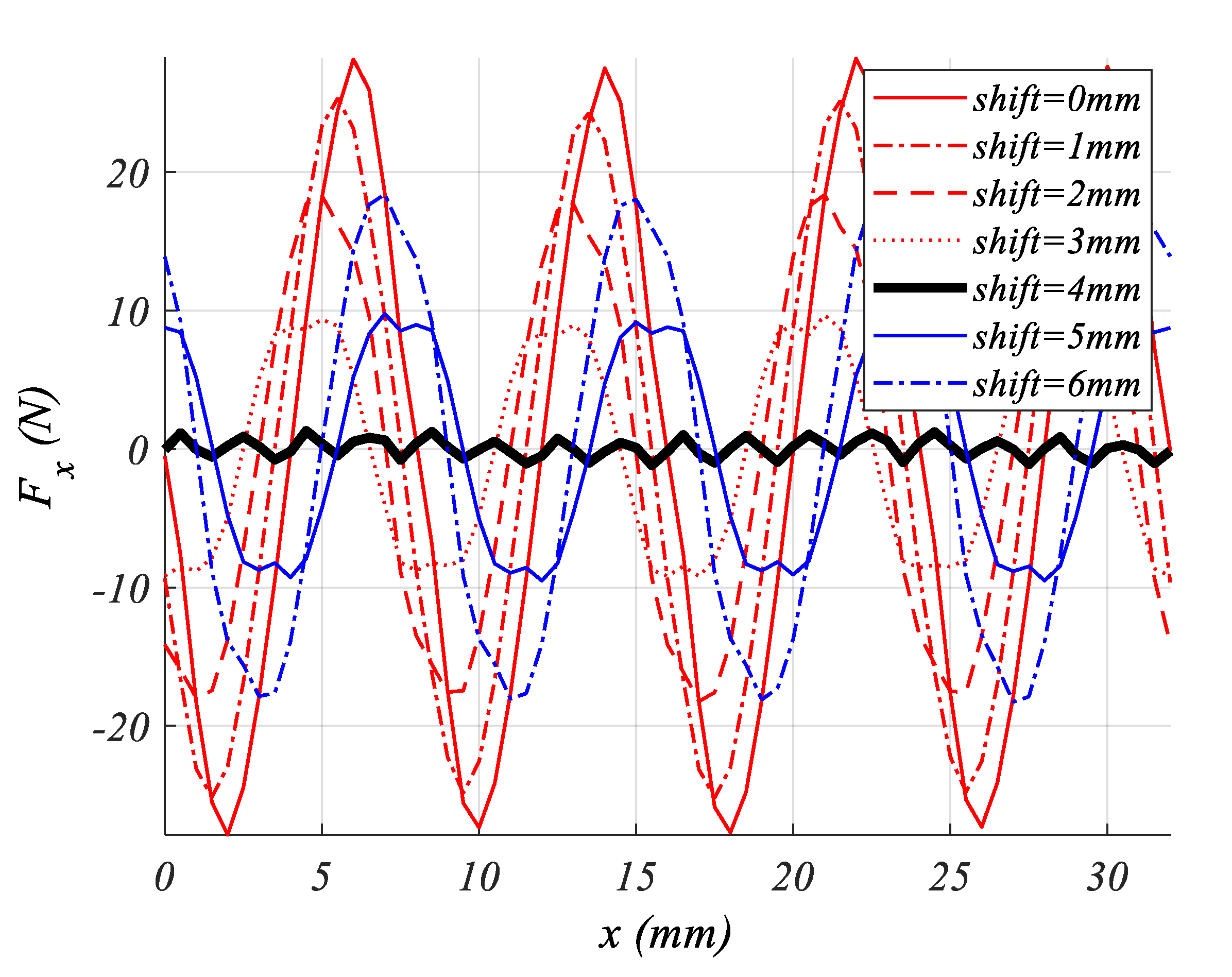
Figure 8 shows the simulation results of the detent force versus the shift for the whole PM-LHRM. The detent force results are minimal
s = 4 mm as predicted by the analytical model, see
Figure 7d. The detent force is computed for the whole PM-LHRM for ranges of shift (
s) and mover positions (
x), which are:
s ϵ [0 ÷ 6 mm, ∆
s = 1 mm] and
x ϵ [0 ÷ 32 mm, ∆
x = 0.5 mm]. The mover runs to the left, being the initial position,
x = 0, the position shown in
Figure 1. The distance covered by the mover, from
x = 0 mm (see
Figure 1) to the position in which stator U core B1 reaches the same relative position of C1 at
x = 0 mm, is the period of detent force (τ), which for this actuator is τ = 8 mm. The results corroborate the analytical results obtained from (9), and the minimum detent force is obtained for a shift of
s = 4 mm (see
Figure 7). Repeating the simulations for the PM-LM structure also finds a minimum in the detent force at the same shift of 4 mm.
5. Comparative Study for Shifted Structures
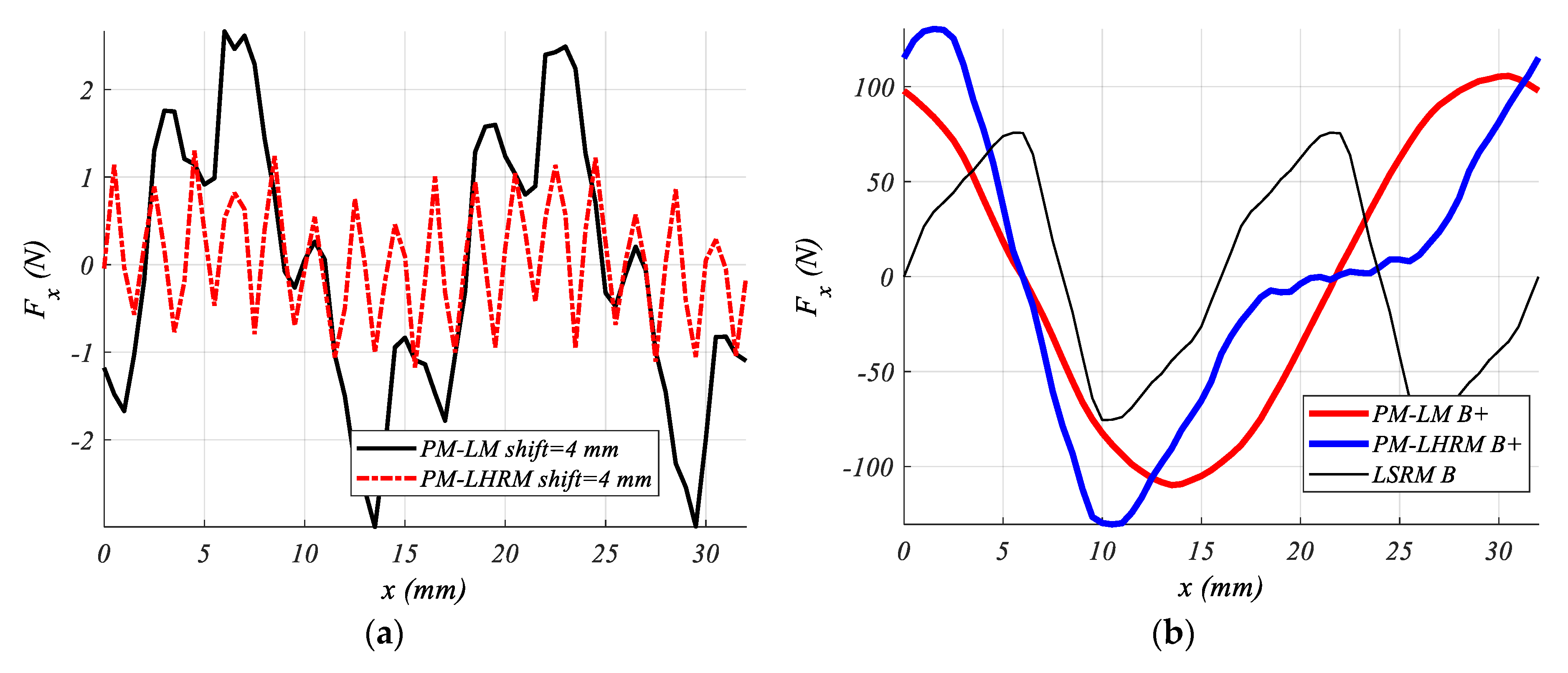
A comparison between the proposed PM-LHRM and the PM-LM simulation results is presented. Both motors are of the same size and have the same shift of
s = 4 mm.
Figure 9a shows the detent force comparison of the two structures, in which the PM-LHRM present a significant lower detent force, meanwhile PM-LM has a wide cycle of the force of 16 mm, with peaks points over 2.5 N and −3 N.
Figure 9b shows the propulsion force comparison results of the PM-LM and PM-LHRM structures, and also the LSRM. As can be seen, the force distributions obtained after shifting are significantly different in both PM motors. The peak forces are 130.4 N for PM-LHRM and 105.7 N for PM-LM, and the average forces are 60 N and 69 N, respectively. From the simulation results presented in
Figure 9a,b, PM-LHRM exhibits a lower detent force and a higher force peak in comparison with PM-LM. The LSRM shows the lowest propulsion force peak at 75 N.
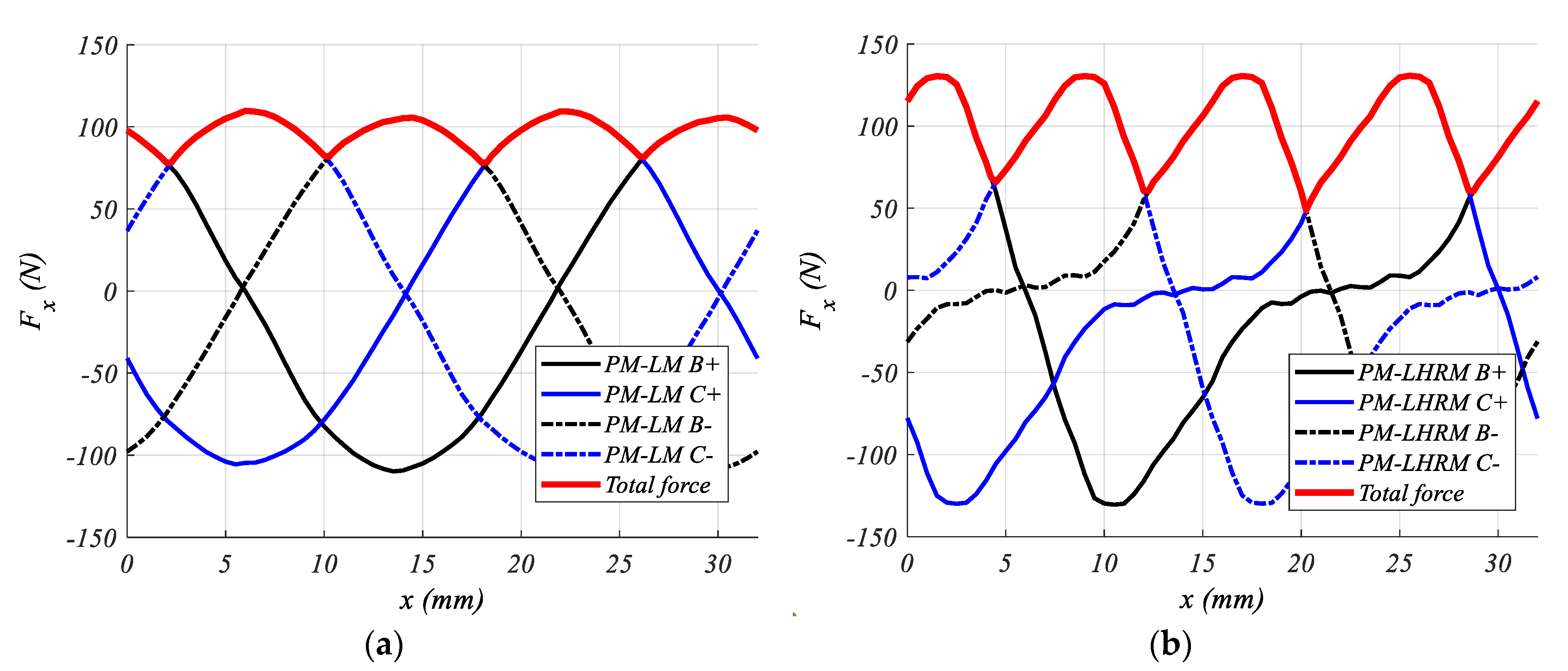
In order to assess the goodness of the proposed actuator versus its PM-LM counterpart,
Figure 10a,b compare their propulsion force profiles, obtained by feeding the phases with a flat current waveform in switched reluctance mode, that is without overlapping phase currents. The phases are fed for obtaining a positive trust in the sequence B+ C- B- C+. The total trust obtained is the enveloping of the force profiles in the red line.
Figure 11 shows the comparison results of the total propulsion force of the three motors analyzed. The main values are summarized in
Table 1, where to complete the study ripple factor is included (see equation 11), having been obtained through the following expression:
In
Figure 11, the work cycle of propulsion force shows a maximum for PM-LHRM, 130 N. For PM-LM shows a propulsion force with a displacement cycle of 8 mm, with a lower maximum of force than the LHRM configuration (109.8 N), and minimum at 80 N. Finally, LSRM shows the lowest propulsion force than the three configurations (75.8 N), and a displacement cycle of 8 mm.
Table 1 collects the three parameters (peak force, average force, and ripple force) obtained from
Figure 11, as well as the detent force peak and rms values obtained from
Figure 9a. PM-LHRM shows the highest force peak, on the other hand, LSRM presents the lowest peak force, similarly, the
Fave, presents the same trend as the
Fpeak profiles. Detent forces present higher values for PM-LM (2.66 N) than PM-LHRM (1.3 N), but in very low percent values from
Fpeak analyzed: 2.4% to 1%, for PM-LM and PM-LHRM configurations, respectively.
6. Verification Results
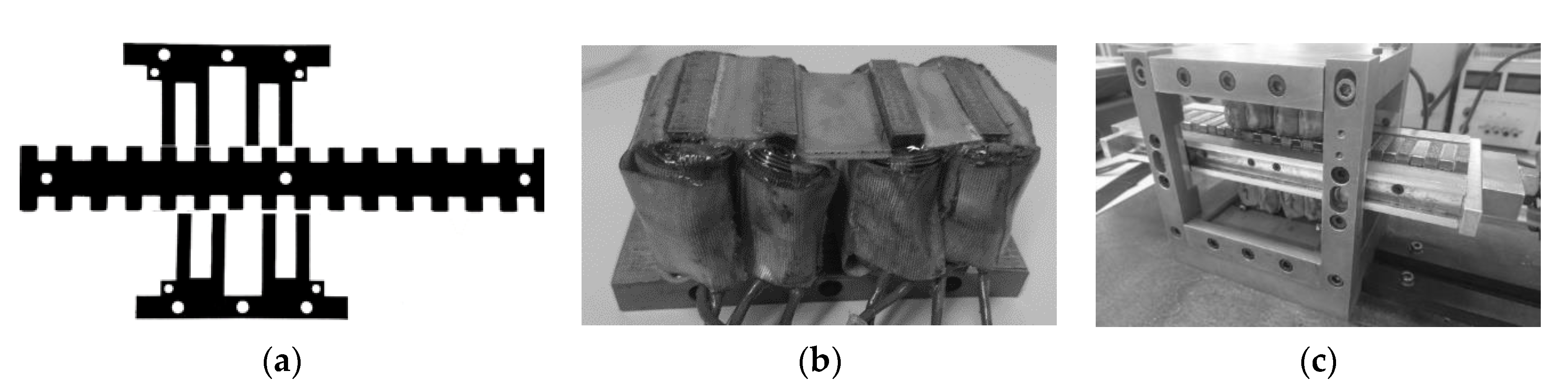
A prototype of the proposed PM-LHRM actuator was built. In
Figure 12a, a lamination of stator U-cores and the mover are shown. A picture of one of the U-core wounded is depicted in
Figure 12b. The complete actuator can be seen in
Figure 12c. The design specifications of the linear hybrid reluctance actuator are those given in the
appendix.
The force measurements were done with a load cell, UTILCELL CR200. On the other hand, the magnetic field of all the permanent magnets were measured on the airgap surface with a gaussmeter model Tenmars TM-197 AC/DC, giving values ranging from ± 0.47 to ± 0.51, giving an acceptable magnetic field symmetry.
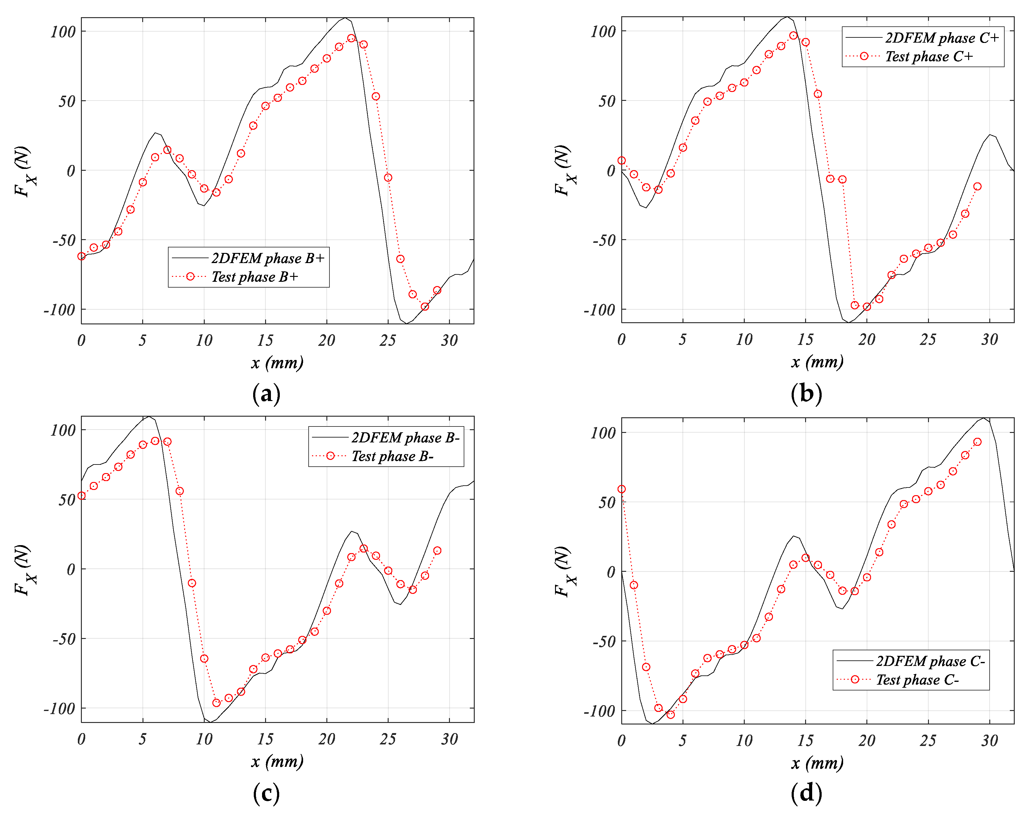
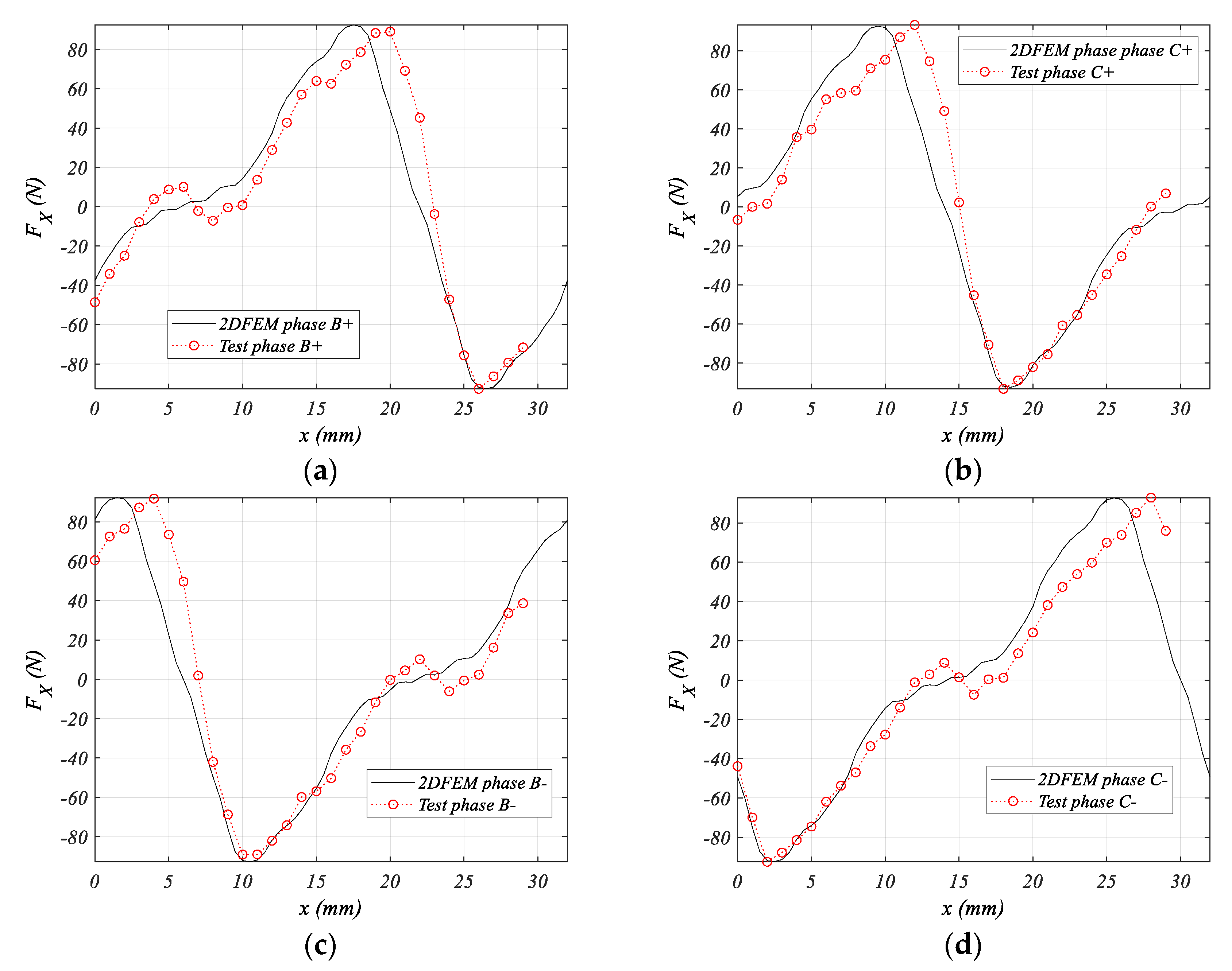
To validate the FEM simulations, a 3D finite element analysis using Altair Flux™ [
40] was performed to account for end-effects. An experimental test set-up (see
Figure 12c) was used to obtain the curve force profile for each phase of the prototype (see
Figure 13 and
Figure 14), feeding one current at a time: I
B+ I
B- I
C+ I
C-, which for
J = 10 A/mm
2 results from a value of 3.12 A. These results are presented in
Figure 13 and
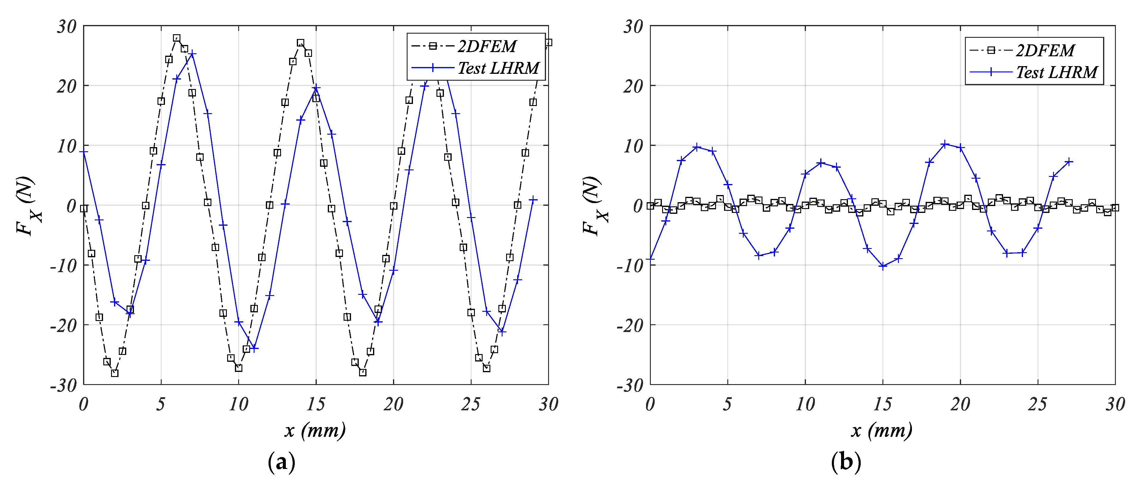
Figure 14 along with the 2DFEM simulation results for each phase for a shift displacement of 0 and 4 mm, respectively. The test system positioning consisted of a calibrated screw (1 mm per revolution) with a range of 28 mm. From these figures, it can be seen a good agreement between simulation and experimental results. It is appreciated there is a slight shift of the experimental values in respect to the simulation, this is due to a positioning error of the screw system.
Figure 15 shows comparison results of the detent force for the two-shift considered. As can be seen, the experimental values of detent force for
s = 4 mm reveals a significant difference between the 2DFEM results.
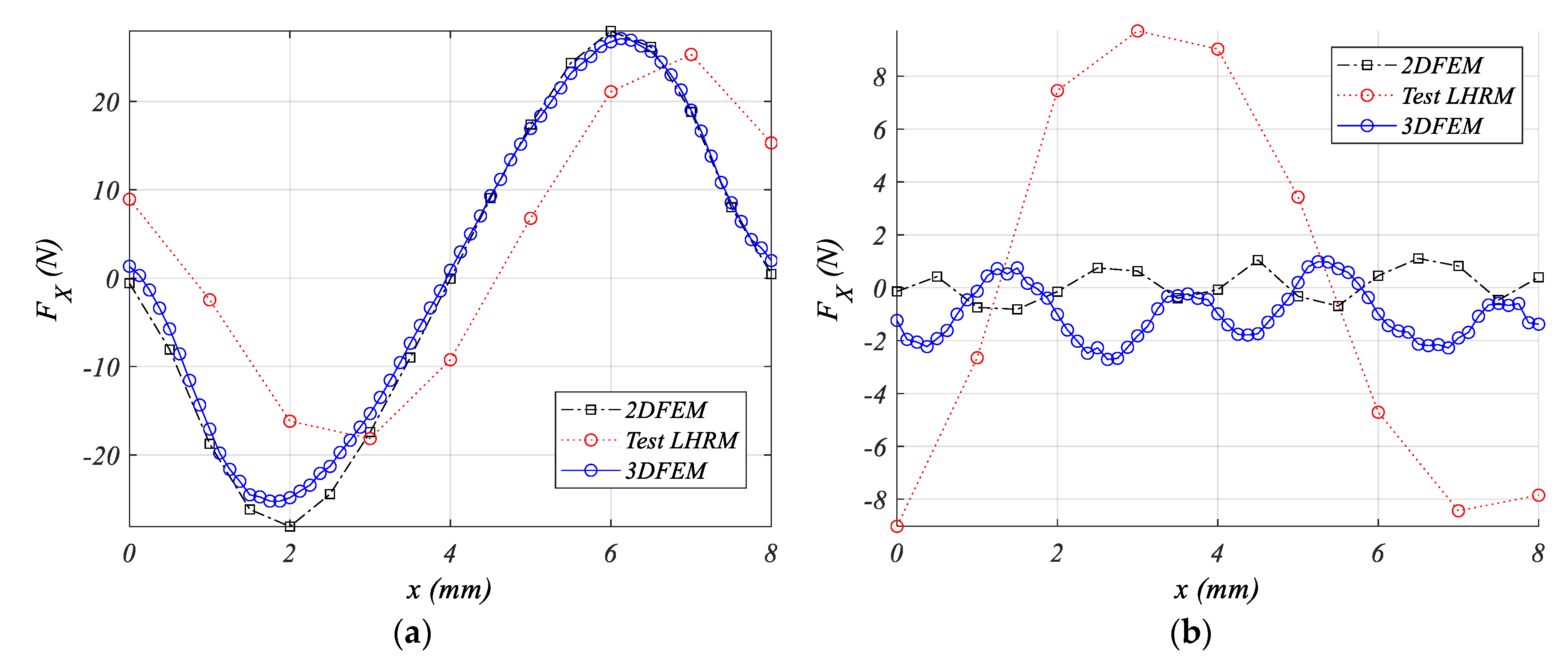
To shed some light on this discrepancy, a 3DFEM [
41] simulation was performed. For
s = 0 mm, there is an acceptable concordance between the results 2DFEM, 3DFEM, and experimental (see
Figure 16a). In contrast, for
s = 4 mm the differences persist (see
Figure 16a), which leads to the belief that end-effects are not relevant enough to produce such difference.
Such deviation in detent force for
s = 4 mm can be due to the combination of three main causes. The first one is due to static friction, which is not accounted for in FEM simulations. The second cause is due to the mechanical assembly tolerances of the prototype. This affects two crucial aspects: (a) different airgap lengths due to constructive defects, and (b) the lower stator shift tolerance. A FEM sensitivity analysis has been carried out for the airgap tolerances (lengths), that is, the upper airgap
, the lower airgap
, and by taking a tolerance range of
mm. The curve patterns of detent force obtained from sensitivity analysis fit with the experimental measurement detent force pattern when
(see
Figure 15b blue line), which indicates the probable existence of this kind of asymmetry, since only for
the detent force is minimum (
s = 4 mm) and follows the pattern shown in
Figure 8 (black line). The influence of the tolerance of the shift of lower semi stator can be seen in
Figure 8. For instance, for
s = 3 mm (see
Figure 8) the detent force pattern matches the experimental detent force (see
Figure 15b). These two observations, different airgap lengths and shift tolerances, lead to the conclusion of the existence of some mechanical asymmetry, not easy to quantify, which affects these highly sensitive parameters (
and produces this significant difference between FEM (2D and 3D) and experimental measures. The third cause of perturbation can be assigned to the end-effects phenomena, which produces a magnetic force at the stator edges [
38,
41].
Despite this deviation in the experimental and FEM results, it is important to point out the relevant reduction (>50%) in the detent force when one stator is shifted from
s = 0 to
s = 4 mm (see
Figure 15), which validates the methodology and the PM-LHRM as an interesting choice in high-density force applications.
7. Conclusions
In this paper, a novel type of two-phase hybrid reluctance actuator (PM-LHRM) is presented. The stator is double-sided and consists of four laminated U cores, two of them are placed on the upper side and the two others on the lower side. The permanent magnets are placed into the mover between their poles and have been disposed of with a determined magnetization. Each phase is energized by its H-bridge to allow the switching of the phase current to a positive value (+I) and to a negative value (–I) in the period of conduction of each phase. The U cores of the lower stator are shifted in respect to the U cores of the upper stator for reducing the detent force. Simulations demonstrate that this actuator doubles the total thrust of an LSRM actuator of the same size, with a reduced detent force. The PM-LHRM was compared with a PM-LM (no poles in the mover), resulting in a lower detent force for s = 4 mm in the PM-LHRM structure and a higher peak and average force, 19% and 3.8%, respectively.
From the results obtained, it can be drawn that the PM-LHRM structure has a better performance since applying a convenient force control (i.e., feeding with an appropriate current waveform), the force the ripple factor can be minimized, and the average propulsion force fit to its maximum value. It has also been revealed that the detent force of this actuator is highly sensitive to constructive defects, especially the airgaps length and the stator shift displacement.


