Abstract
Computations of quasi-dynamic electromagnetic field of induction machines using the complex magnetic vector potential require the use of the so-called effective magnetization curves, i.e., such in which the magnetic permeability is proportional to the amplitudes of magnetic flux density B or magnetic field strength H, not their instantaneous values. There are several definitions of that parameter mentioned in the literature provided for the case when B or H are monoharmonic. In this paper, seven different methods of determining the effective magnetization curves are compared in relation to the use of a field-circuit multi-harmonic model of an induction machine. The accuracy of each method was assessed by computing the performance characteristics of a solid-rotor induction machine. One new definition of the effective permeability was also introduced, being a function of multiple variables dependent on amplitudes of all the harmonics considered. The analyses demonstrated that the best practical approach, even for the multi-harmonic case, is to express the effective magnetic permeability as the ratio of the amplitudes of the fundamental harmonics of the magnetic flux density and the magnetic field strength, and assuming the sinusoidal variation of the latter.
1. Introduction
Numerical models based on the use of the finite element method have become an indispensable tool in the design of electrical machines. As is well known, the most accurate approach for overall consideration of physical phenomena in an analyzed converter is the use of time-domain models. Unfortunately, this approach usually involves significant computational cost, sometimes making its practical application impossible. For that reason, it is justified to explore methods which allow, particularly in the analysis of steady states, to achieve similar results, but in a much shorter time. While analyzing induction machines, one of such methods is the use of the multi-harmonic field-circuit model [1,2,3,4,5,6,7,8,9]. The results presented in [1,2,9] prove that this type of the field-circuit model can be particularly useful when analyzing steady states of the special constructions of induction machines (single-phase machines, high-speed solid-rotor machines). As demonstrated by Garbiec et al., with an appropriate modification of the coupling scheme between individual sub-models, the multi-harmonic field-circuit model makes it possible to achieve comparable calculation results with those obtained using the time-domain model, at a calculation cost comparable to the monoharmonic model. The multi-harmonic model in this case is understood as the De-Gersem type model formulated using the magnetic vector potential, where permeance slot harmonics of the magnetic field distribution in the air gap are extracted via Fourier transform of an air-gap magnetic field. These harmonics can affect the power losses in the rotor and the electromagnetic torque developed by the machine. The magnetic field in the stator in these models is considered as a function of the fundamental time harmonic only.
The application of the above-mentioned approach essentially involves the problem of modeling the nonlinearity of the magnetic materials. Taking this into account in the monoharmonic field models based on the use of the complex magnetic vector potential method is not a new task and it has been described to date in several works, including [10,11,12,13,14,15,16]. They propose several different methods of defining the so-called effective magnetic permeability based, among others, on the development of nonlinear waveforms in the Fourier series [14,16], averaging the magnetic reluctivity [10,15,16] or equivalence of energy stored in ferromagnetic components [10,11,12,13]. However, analyzing the conclusions drawn in the mentioned works, it is not possible to clearly state which method of defining the effective magnetic permeability will be most appropriate when using the multi-harmonic model with a strong coupling, as proposed by Garbiec et al. Some of them assume the sinusoidal variation of the magnetic flux density in calculating the effective magnetic permeability (which facilitates the calculations using the magnetic vector potential) [12,13,14,15], while others assume that it should be determined assuming sinusoidal variation of the magnetic field strength, or that it is insignificant for the accuracy of the calculations [10,11,14]. The latter approach was adopted in the authors’ previous work, and satisfactory results were achieved [9]. It was based on the results of the earlier work of the authors, where the effective magnetic permeability defined with the assumption of the sinusoidal variation of the magnetic field strength provided correct results, modeling a solid-rotor induction machine with the use of the multi-harmonic field-circuit model with a weak coupling [17]. To the best of authors’ knowledge, the research providing an analysis of the accuracy of definitions of the effective magnetic permeability on the results of computations using multi-harmonic field-circuit models was not reported.
This paper is a continuation of works by Garbiec et al. that aim at an in-depth verification of the De-Gersem type multi-harmonic complex model of induction machines from the point of view of their application in designing and optimization of real machines. The authors focus on the analysis of the impact of formulating the effective magnetic permeability. For that purpose, the basic operating characteristics of an exemplary machine were calculated for seven different methods of formulating the effective magnetic permeability. The first six methods use existing definitions derived in literature. The available formulas use averaging of magnetic reluctivity in terms of mean or RMS value. Also, the Fourier series truncated to the fundamental component and assuming sinusoidal variation of the magnetic flux density or magnetic field strength is used [14,15,16]. The seventh method considered in this paper is a new approach proposed by the authors that relies upon formulating the so-called multidimensional effective magnetic permeability. The results of calculations were compared with those obtained with the time-domain model and with the results of measurements performed on the physical model under one of the previous works where the efficient computational method for fast determination of the performance characteristics of solid-rotor induction machines was presented [17].
2. Mathematical Model
2.1. Effective Magnetic Permeability
Definition of the effective magnetic permeability, as used in the previous works of the authors [9,14,16,17], is the reference point for the considerations presented herein:
where —amplitude of the sinusoidal magnetic field strength H, and —DC magnetic permeability. The above definition corresponds to the ratio of the fundamental harmonic amplitude of the magnetic flux density waveform (obtained on the assumption of the sinusoidal variation of the magnetic field strength) and . This approach requires a successive determination of the magnetic field strength in a given iteration of the algorithm based on the knowledge of its value determined in the previous iteration.
Assuming the sinusoidal variation of the magnetic field strength, two further definitions can be introduced [16]:
where . The expressions (2) and (3) correspond to the inverse of the mean value and the inverse of the RMS value of the magnetic reluctivity obtained for the half of the period.
Similarly, the definitions of the effective magnetic permeability can be derived, assuming the sinusoidal variation of the magnetic flux density B with the amplitude [15,16]:
Each of those definitions assumes that the magnetic saturation coefficient of the ferromagnetic material is a function of the fundamental harmonic of the magnetic field only, expressed by B or H. The definitions (1), (3), (5) and (6) are taken from the literature, whereas (2) and (4) are the equivalents of (5) and (1), respectively.
2.2. Analyzed Machine
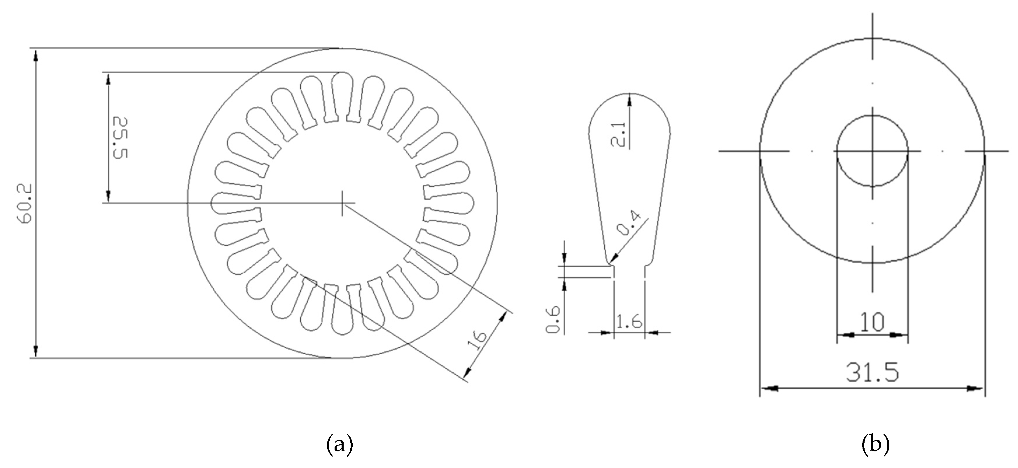
In this work, the effect of how the effective permeability is taken into account was examined on the example of a high-speed induction machine with a uniform solid rotor analyzed previously by Garbiec et al. The basic data of the considered motor is presented in Figure 1 and Table 1.
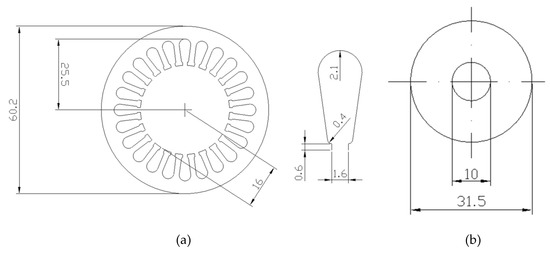
Figure 1.
Solid-rotor induction machine taken into consideration: (a) dimensions of the stator package (cross section area), (b) dimensions of the rotor.

Table 1.
Basic specifications of tested induction motor.
A field-circuit multi-harmonic model with a strong coupling was developed for the analyzed machine. Based on the results of the analysis presented in by Garbiec et al., it was decided to reduce the number of the rotor models to three, i.e., those related to the fundamental harmonic of the magnetic field in the air gap and two most influential higher slot harmonics with ordinal numbers—11 and 13. Neglecting the rotor-end effects the system of equations describing the model takes the form [9]:
where: —matrix describing the magnetic and electrical properties of materials, —matrix describing the distribution and connection method of the stator winding, —matrices describing coupling between the rotor models and the stator model, —stator winding impedance matrix, —vector of the nodal values of the complex magnetic vector potential, —vector of the amplitudes of the loop currents in the stator winding, —vector of complex circulations of the magnetic field strength vector, —vector of the complex voltage amplitudes in the loops in the stator winding circuit.
For a comparison, in this paper, calculations were also carried out using a developed complementary time-domain model which uses the DC magnetization curves. The equations for such a model after discretization via Galerkin procedure and the implicit Euler method take the form:
where: S—reluctivity matrix, G—conductivity matrix, D—matrix describing the winding, K—matrix describing the winding connection method, R—winding resistance matrix, L—winding leakage inductivity matrix, ∆t—integration step, φ—vector of nodal values of the vector magnetic potential, i—vector of instantaneous values of the stator currents, e—vector of the instantaneous supply voltages values. The rotational movement was modeled using the moving band technique. The computing cost for the multi-harmonic model (when choosing an appropriate coupling scheme) is of the order of a per cent compared to that using the time-domain model [9]. This is the main reason for developing the model described by the Equation (7), however, in this paper the authors focus on the accuracy rather than on the computing cost. The nonlinearity in both above formulated computational problems is solved iteratively by updating, respectively and from iteration to iteration unless the relative change of solution is below a prescribed value.
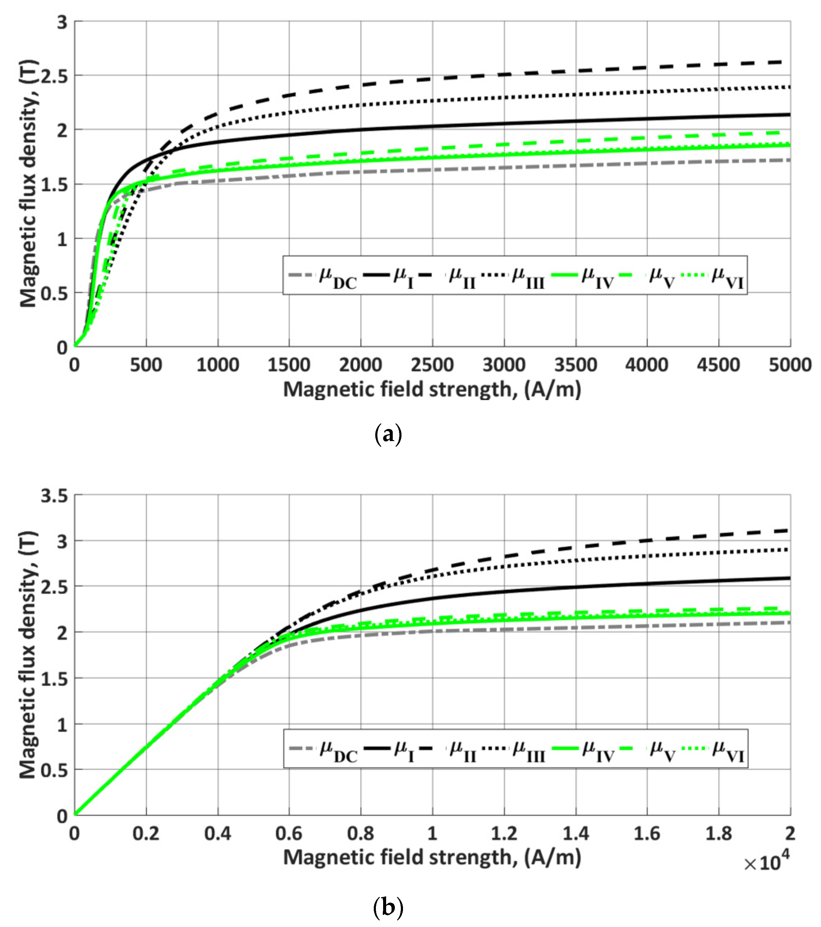
Based on the DC magnetization curves for the stator and rotor materials, the effective magnetization curves were determined according to (1)–(6) (Figure 2). For saturated material, each effective magnetization curve is noticeably characterized by higher magnetic flux density values compared to the characteristic for the direct current. At a low level of magnetic saturation, the effective curves ale very close to the DC curve. Furthermore, a relatively small difference is found for different curves determined assuming the sinusoidal variation of the magnetic flux density for the rotor material. Moreover, the curves calculated with the assumption of a sinusoidal variation of the magnetic flux density are closer to the DC curve than the case with the assumption of a sinusoidal variation of the magnetic field strength. Additionally, curves (4)–(6) are closer to each other than (1)–(3). This is due to the completely different shape of the magnetic flux density waveforms (magnetic field strength) in the case when the magnetic field strength (magnetic flux density) is sinusoidal.
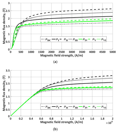
Figure 2.
Effective magnetization curves determined from the expressions (1)–(6): (a) stator, (b) rotor.
3. Calculation Results
The magnetization curves shown in Figure 2 were used to determine three basic operational characteristics of the machine (electromagnetic torque, RMS phase current, power losses in the rotor) vs. rotational speed at two different supply voltages (phase voltages), i.e., 50 V (rated) and 75 V (150% of the rated value) without changing the frequency of power supply. Note that the effective magnetic permeability for the rotor models is determined in each iteration based on the knowledge of the magnetic field strength distribution (expressions (1)–(3)) or magnetic flux density ((4)–(6)) only for the rotor model associated with the fundamental harmonic of the magnetic field distribution. The characteristics calculated were compared with the results of calculations using time-domain model, as described in Section 2. It should be kept in mind that the considered multi-harmonic model, despite the associated mathematical burden, is a simplified approach. This simplification can be observed in e.g., the obtained steady-state distributions of the magnetic flux over the machine cross-section shown in (Figure 3). Based on the results of that comparison, two groups of characteristics were created (Figure 4) showing the total relative percentage calculation error for the three determined quantities (electromagnetic torque, RMS phase current, power loss in the rotor) in relation to the calculation results obtained from the model (8):
where: , , , , —respectively, electromagnetic torque, stator RMS phase current, power loss in the rotor calculated with the model formulated in the time domain, —respectively, electromagnetic torque, stator RMS phase current, and power loss in the rotor calculated using the multi-harmonic model. Table 2 shows the averaged values of that indicator against the entire speed range considered.
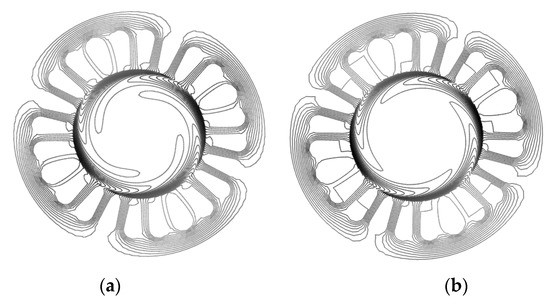
Figure 3.
Comparison of sample distributions of magnetic flux over cross section of the motor at rotor slip equal to 10%: (a) time-domain model, (b) multi-harmonic model with all harmonics considered (the magnetic field in the rotor area is a sum of the complex magnetic vector potential distributions obtained from solution of (7) for the individual rotor submodels).
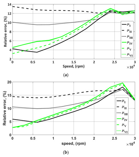
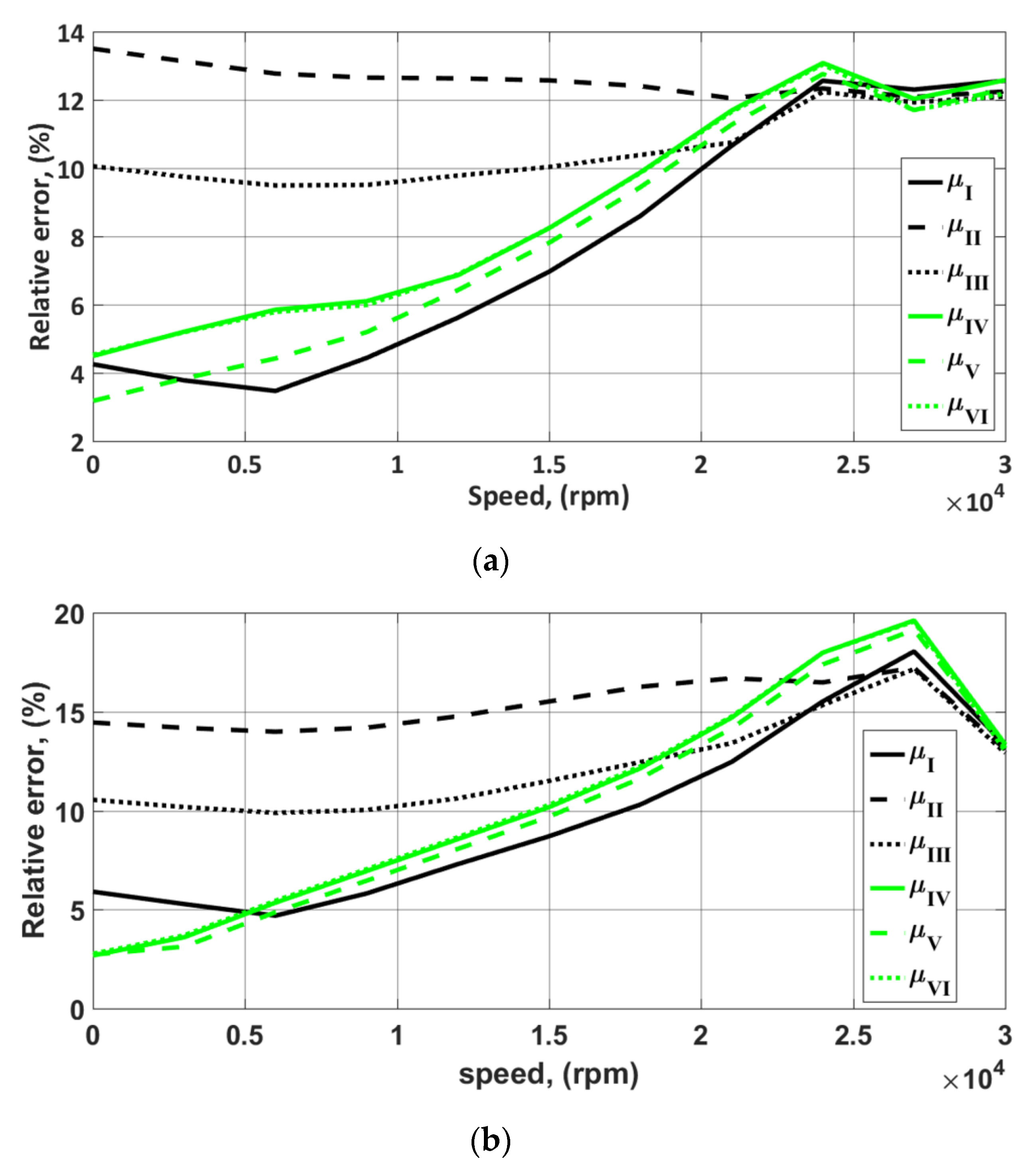
Figure 4.
Variation of relative error (9) vs. rotational speed using various methods of calculating the effective magnetic permeability for the RMS phase supply equal to: 50 V (a), and 75 V (b).
Table 2.
Averages percent value of the relative error for N = 11 considered points of the curves.
Out of the definitions of the effective magnetic permeability considered, noticeably the best results were achieved using μI (originally used in calculations). Slightly worse results (except for the locked rotor state) can be obtained with the definitions assuming the sinusoidal variation of the magnetic flux density. On the other hand, an interesting conclusion is that the method how the nonlinearities are taken into account has practically no impact on the results of calculations for near-synchronous rotational speeds. It is caused by a much lower saturation of the rotor surface, crucial from the point of view of the machine properties, and consequently use by the time-harmonic model (7) similar values of effective permeability (see Figure 2). An increased error in the range of nominal operation point (21–27 krpm) is an adverse trend observed. However, note that the waveforms of the global error indicator shown in Figure 4 provide information on the discrepancy in the results of calculations of power losses in the rotor (). The results of those calculations are distinguished by the greatest discrepancy (for μI and N = 11 considered points of the curve = 15.42% at 50 V and 19.32% at 75 V), thus overestimate the global error indicator. In the rotational speed range from 21,000 rpm to 27,000 rpm, the average electromagnetic torque error and the RMS current error is 7.56% and 1.43% at 50 V, 10.93% and 1.67% at 75 V, respectively.
Calculating the effective magnetic permeability based on the distribution of the magnetic field strength or magnetic flux density, determined only for the model associated with the fundamental field harmonic in the machine air gap, can raise doubts. To take into account the impact of the higher harmonics and to assess the error related to this assumption, a new definition of the multidimensional effective magnetic permeability was proposed:
where , , are the magnetic field strength amplitudes related to the fundamental, eleventh and thirteenth harmonics of the field and
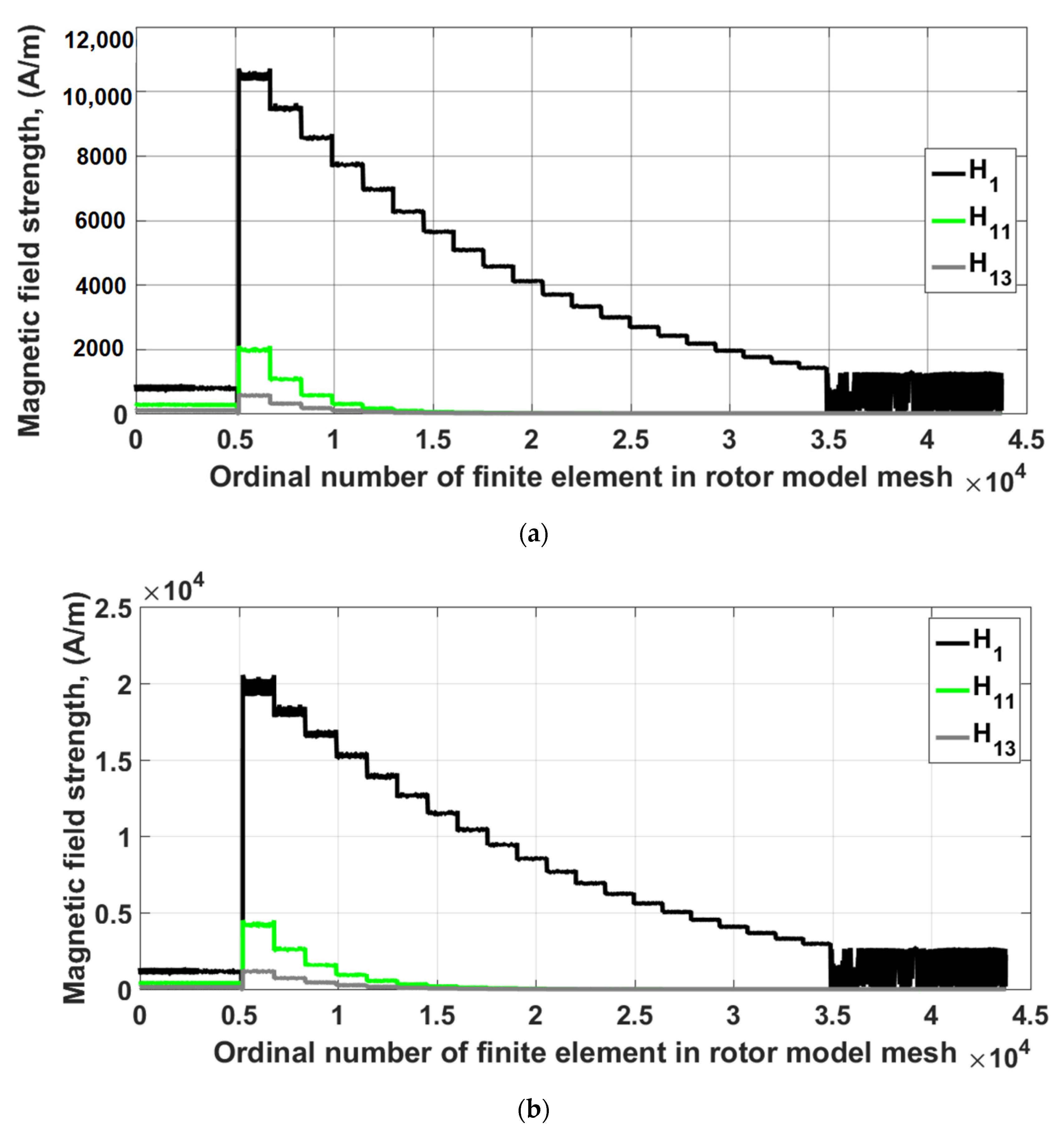
For zero values of the higher harmonics, the definition (10) is equivalent to (1). This approach only slightly complicates the model implementation (in each algorithm iteration the distribution of the magnetic field strength in all considered rotor models needs to be obtained). An advantage of this expression, however, is the fact that effective permeability can be expressed before starting the calculations, without knowing the individual amplitudes. For the expression (10), it is possible since does not depend on the phase angles of individual harmonics. In general, this occurs when the frequencies of the higher harmonics are the multiples of the fundamental harmonic. The value of the multidimensional effective permeability is determined only once as a multidimensional table for the assumed variability ranges of individual harmonics of the magnetic field strength. Figure 5 shows the determined distribution of this quantity assuming that = 0 A/m. The multidimensional permeability determined was used again for calculations and compared with the results obtained for (1). The result of that comparison is shown in Table 3. As can be seen, the application of the multidimensional effective permeability brings only slight improvement to the accuracy of calculation results. This is due to relatively low magnetic field strength values in the areas of the models associated with the slot harmonics, as illustrated in Figure 6.
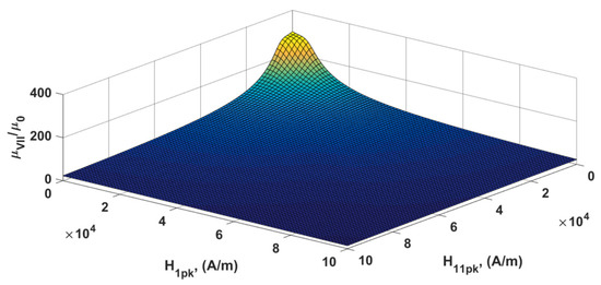
Figure 5.
Relative multidimensional effective permeability calculated for the DC magnetization curve of the rotor, assuming zero value of the magnetic field strength of the thirteenth harmonic.
Table 3.
Averages percent value of the relative error for N = 11 considered points of the curves.
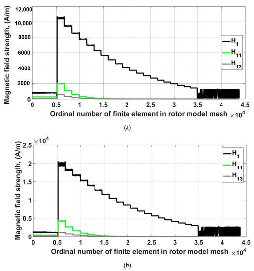
Figure 6.
Comparison of the magnetic field strength values in the individual elements creating FE rotor mesh for the rotor models associated with the considered harmonics for a 20% slip: (a) at 50 V, (b) at 75 V.
4. Physical Validation
The analysis demonstrated that, from a practical point of view, it is sufficient to assume the first definition of the effective magnetic permeability, both due to the accuracy of calculations, and ease of implementation. It should be mentioned that, when adopting the sinusoidal variation of the magnetic field strength in determining the effective magnetic permeability, the fixed point method is applied in the multi-harmonic model to solve the nonlinearity problem, which is easy to implement, and it is distinguished by good convergence quality in case of time-harmonic magnetic fields. In the latter case, it is recommended to use the Newton–Raphson method [16].
The model developed, together with the first definition of the effective magnetic permeability, was applied to calculate the RMS current of a real machine (supplied via a quasi-square wave voltage inverter, fundamental frequency of supplying voltage equal to 500 Hz) with three different solid rotors tested by Garbiec and to compare the results with the calculations performed using a model with a weak coupling the same definition of the effective magnetic permeability applied (see Figure 7).
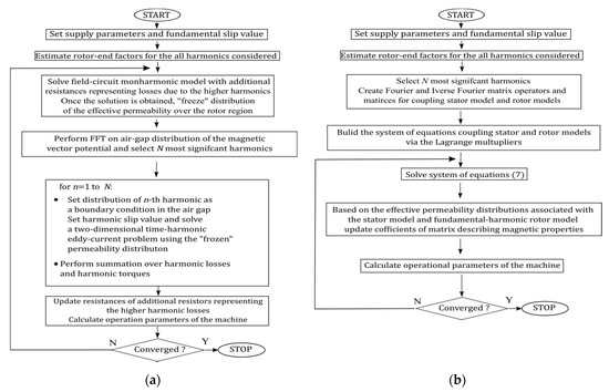
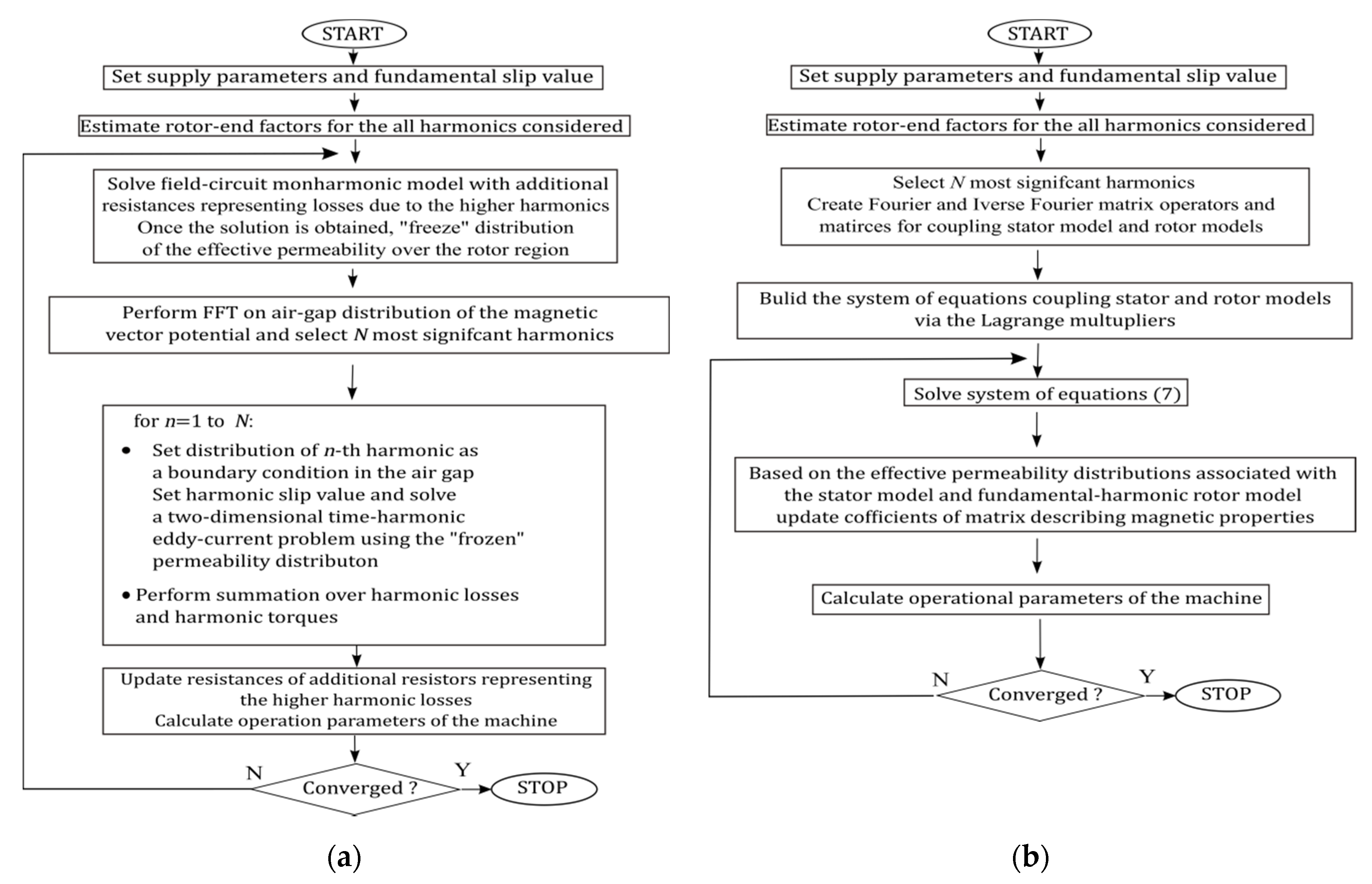
Figure 7.
Comparison of the ideas of the different multi-harmonic model: (a) model with the weak coupling, (b) model with the strong coupling.
As it can be seen in the figure the idea of using the model with the strong coupling is to simultaneously solve the problem composed of a few submodels (the stator model and rotor models associated with the considered harmonics) coupled by appropriate boundary conditions imposed on the interface boundary in the air gap. This formulation results in one system of equations and determination of the magnetic vector potential distribution for all models via single solution of (7). The interface conditions in the air-gap are formulated with the use of matrix operators of the Fourier transform and the inverse Fourier transform, as shown in Garbiec at. al, enforce the propagation of only the selected harmonics of the air-gap field distribution between the stator model and the considered rotor models. All rotor models act via the same constraint on the stator model. In the considered model with the weak coupling, the monoharmonic field-circuit model is used. The power loss due to slot harmonics is estimated by means of extraction of these harmonics from the calculated distribution of the magnetic vector potential. In this way it is possible to solve the field problem limited to only the area of rotor. In this approach the power factor, torque and stator current can be appropriately corrected, although there is no backward relationship, i.e., the air-gap field remains unaffected by these effects. To this end, it was also necessary to take into account the rotor-end effect [18].
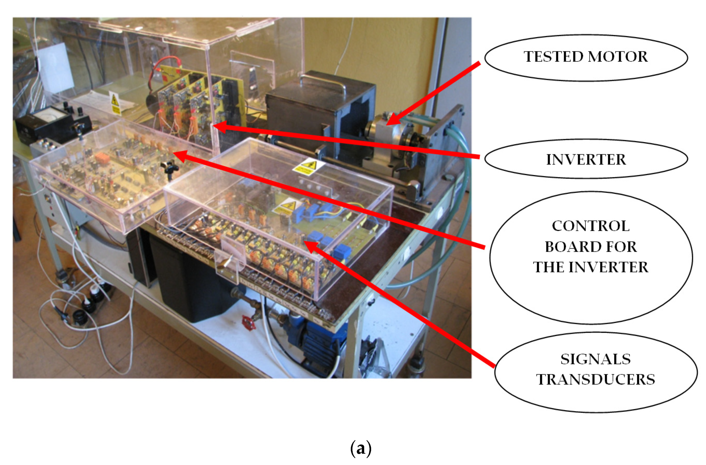
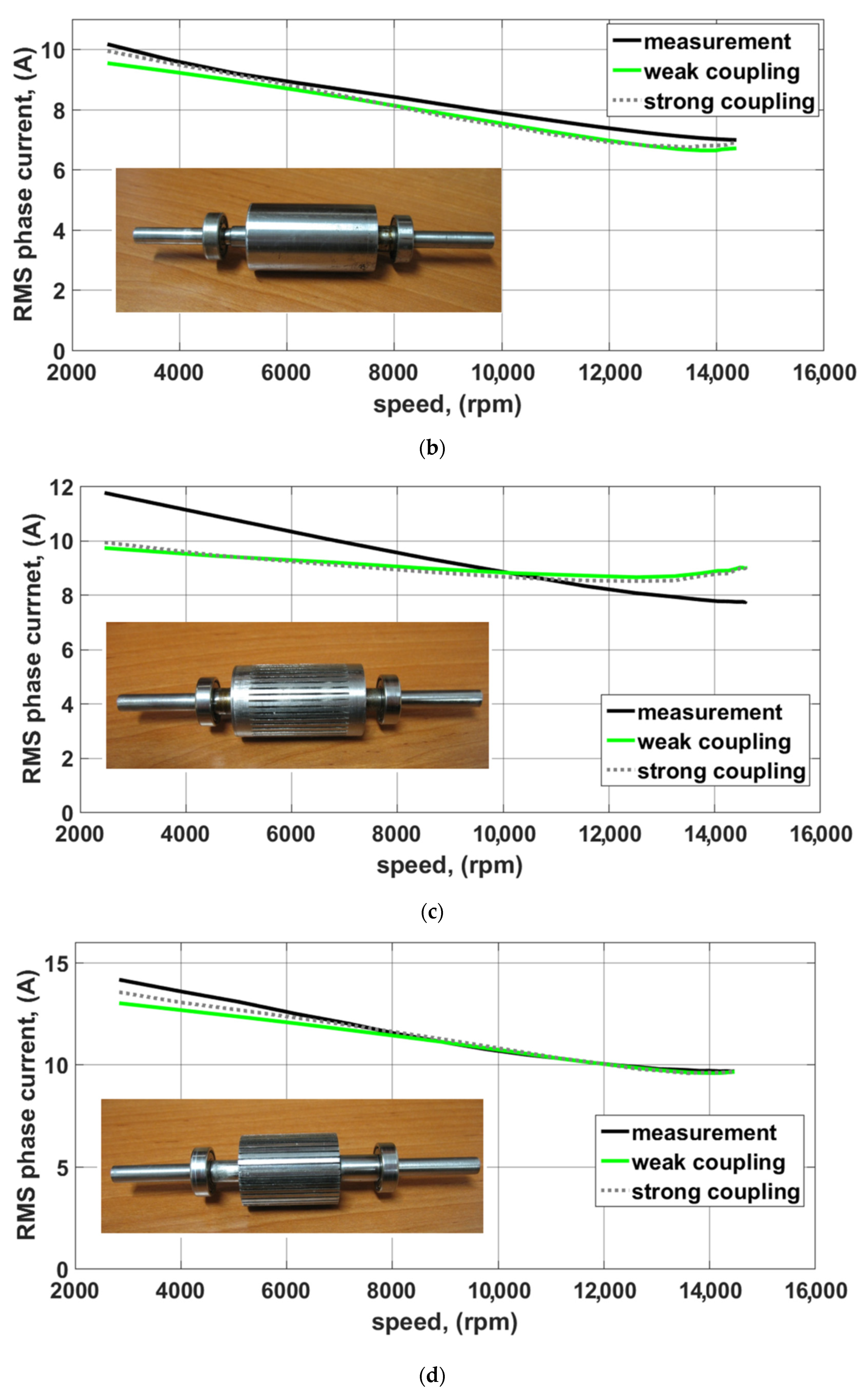
The physical test-stand and result of the comparison of computed and measured data for the machine with different rotors is shown in Figure 8. With the application of the multi-harmonic model with the strong coupling and with the modified sub-model coupling scheme, it was possible to achieve practically identical calculation results, yet in a shorter time by approx. 30%. The errors found result mainly from supplying the physical model via a quasi-square wave voltage inverter (in numerical models, the pure sine-wave voltage supply with an RMS value equal to the RMS value of the measured voltage is assumed).


Figure 8.
Comparison of calculation results with the multi-harmonic model with the weak coupling to those of calculations with the multi-harmonic model with the strong coupling, with the measurement results [17]. (a) Physical test-stand, (b) RMS current vs. rotor speed for the machine equipped with an uniform rotor, (c) RMS current vs. rotor speed for the machine equipped with a slitted rotor with uniform end regions, (d) RMS current vs. rotor for a machine equipped with a slitted rotor with slits through the whole length.
5. Conclusions
The comparison of various methods for calculating the effective magnetic permeability for a multi-harmonic model of a solid-rotor induction machine carried out in the study proved that, from a practical point of view, the best results are obtained using the basic definition, described by Equation (1). Determining the effective magnetic permeability as the ratio of the magnitudes of the fundamental harmonics of the magnetic flux density and the magnetic field strength calculated assuming the sinusoidal variation of the latter allows for an easy implementation of the algorithm which is important from practical point of view. Furthermore, it was demonstrated that, in the studied case, the most influential magnetic saturation effects come from the fundamental harmonic of the magnetic field which means that the slot harmonics of the air-gap magnetic flux density do not have to be computed in that process. For the same definition of the effective magnetic permeability and an appropriate modification of the coupling scheme, it is possible to obtain practically the same results as in the case of the multi-harmonic model with the weak coupling, but yet in a shorter time. Another step to take will be to conduct detailed research using the developed model to analyze the magnetic saturation effects in the squirrel cage induction machines with both three- and single-phase windings.
Author Contributions
Conceptualization, T.G. and M.J.; methodology, T.G. and M.J.; software, T.G.; investigation, T.G.; resources, T.G.; data curation, T.G.; writing—original draft preparation, T.G.; writing—review and editing, M.J.; visualization, T.G.; supervision, M.J.; project administration, T.G. All authors have read and agreed to the published version of the manuscript.
Funding
This research received no external funding.
Conflicts of Interest
The authors declare no conflict of interest.
References
- De Gersem, H.; Hameyer, K. Air-gap flux splitting for the time-harmonic finite-element simulation of single-phase induction machines. IEEE Trans. Magn. 2002, 38, 1221–1224. [Google Scholar] [CrossRef]
- De Gersem, H.; De Brabandere, K.; Belmans, R.; Hameyer, K. Motional time-harmonic simulation of slotted single-phase induction machines. IEEE Trans. Energy Convers. 2002, 17, 313–318. [Google Scholar] [CrossRef]
- Räisänen, V.; Suuriniemi, S.; Kurz, S.; Kettunen, L. Rapid Computation of Harmonic Eddy-Current Losses in High-Speed Solid-Rotor Induction Machines. IEEE Trans. Energy Convers. 2013, 28, 782–790. [Google Scholar] [CrossRef]
- Räisänen, V. Air Gap Fields in Electrical Machines: Harmonics and Modeling of Movement. Ph.D. Thesis, Tampere University of Technology, Tampere, Finland, 2015. [Google Scholar]
- Räisänen, V.; Suuriniemi, S.; Kettunen, L. Generalized Slip Transformations and Air-Gap Harmonics in Field Models of Electrical Machines. IEEE Trans. Magn. 2016, 52. [Google Scholar] [CrossRef]
- Mezani, S.; Laporte, B.; Takorabet, N. Saturation and space harmonics in the complex finite element computation of induction motors. IEEE Trans. Magn. 2005, 41, 1460–1463. [Google Scholar] [CrossRef]
- Ouazir, Y.; Takorabet, N.; Ibtiouen, R.; Touhami, O.; Mezani, S. Consideration of space harmonics in complex finite element analysis of induction motors with an air-gap interface coupling. IEEE Trans. Magn. 2006, 42, 1279–1282. [Google Scholar] [CrossRef]
- Rainer, S.; Biro, O.; Stermecki, A.; Weilharter, B. Frequency Domain Evaluation of Transient Finite Element Simulations of Induction Machines. IEEE Trans. Magn. 2012, 48, 851–854. [Google Scholar] [CrossRef]
- Garbiec, T.; Jagiela, M.; Kulik, M. Application of Nonlinear Complex Polyharmonic Finite-Element Models of High-Speed Solid-Rotor Induction Motors. IEEE Trans. Magn. 2020, 56. [Google Scholar] [CrossRef]
- Paoli, G.; Bíró, O.; Buchgraber, G. Complex representation in nonlinear time harmonic eddy current problems. IEEE Trans. Magn. 1998, 34, 2625–2628. [Google Scholar] [CrossRef]
- Vassent, E.; Meunier, G.; Sabonnadier, J.C. Simulation of induction machine operation using complex magnetodynamic finite elements. IEEE Trans. Magn. 1989, 25, 3064–3066. [Google Scholar] [CrossRef]
- Hedia, H.; Remacle, J.-F.; Dular, P.; Nicolet, A.; Genon, A.; Legros, W. A sinusoidal magnetic field computation in nonlinear materials. IEEE Trans. Magn. 1995, 31, 3527–3529. [Google Scholar] [CrossRef]
- Stermecki, A.; Biro, O.; Preis, K.; Rainer, S.; Ofner, G. Numerical analysis of steady-state operation of three-phase induction machines by an approximate frequency domain technique1. E I Elektrotech. Inftech. 2011, 128, 81–85. [Google Scholar] [CrossRef]
- Takorabet, N.; Laporte, B.; Mezani, S. An approach to compute saturated induction motors in steady state. In Proceedings of the IEEE International Electric Machines and Drives Conference, Madison, WI, USA, 1–4 June 2003; Volume 2, pp. 1646–1650. [Google Scholar] [CrossRef]
- Du Terrail, Y.; Sabonnadiere, J.C.; Masse, P.; Coulomb, J.L. Nonlinear complex finite elements analysis of electromagnetic field in steady-state AC devices. IEEE Trans. Magn. 1984, 20, 549–552. [Google Scholar] [CrossRef]
- Arkkio, A. Analysis of Induction Motor Based on the Numerical Solution of the Magnetic Field and Circuit Equations. Ph.D. Thesis, Helsinki University of Technology, Espoo, Finland, 1987. [Google Scholar]
- Garbiec, T. Fast Computation of Performance Characteristics for Solid-Rotor Induction Motors with Electrically Inhomogeneous Rotors. IEEE Trans. Energy Convers. 2016, 31, 1688–1696. [Google Scholar] [CrossRef]
- Pyrhonen, J.; Nerg, J.; Kurronen, P.; Lauber, U. High-Speed High-Output Solid-Rotor Induction-Motor Technology for Gas Compression. IEEE Trans. Ind. Electron. 2009, 57, 272–280. [Google Scholar] [CrossRef]


© 2020 by the authors. Licensee MDPI, Basel, Switzerland. This article is an open access article distributed under the terms and conditions of the Creative Commons Attribution (CC BY) license (http://creativecommons.org/licenses/by/4.0/).