Abstract
GaN-based power semiconductors exhibit small on-resistance and high dv/dt of the switch characteristics, thereby enabling the construction of high-efficiency, high-density semiconductor systems with fast switching and low power loss characteristics and miniaturization of passive devices. However, owing to the characteristics of GaN devices that result in them being significantly faster than other devices, the accuracy of the switching transient response significantly affects the noise or inductance in the device. Therefore, securing sufficient sensor bandwidth is considerably important for accurate current measurement in GaN-based devices. Conversely, the current sensor in the form of a non-insulated coil must secure sufficient bandwidth and overcome the tradeoff relationship with measurement sensitivity; moreover, the sensor configuration must be applicable to various power semiconductor types. This study proposes a current sensor model that applies the principle of the printed circuit board Rogowski coil to a surface mount device-type GaN-based half-bridge structure. This structure is applicable to a nonmodular power converter and is designed to secure sufficient bandwidth with a minimum area while simultaneously exhibiting high sensitivity. For the coil design, mutual inductances with existing coil structures were compared and analyzed, and the frequency response and magnetic analysis were evaluated. Experimental verification was performed and the transient response characteristics in various DC voltage ranges are discussed.
1. Introduction
In recent times, power semiconductors, such as SiC and GaN, having wide band gap characteristics have contributed significantly to improving the efficiency and density of power converters owing to their low power consumption, miniaturization of passive devices, and high stability at high temperatures [1,2]. Among them, GaN devices have the advantage of having a faster switching speed than conventional Si device-based power semiconductors owing to their low on-resistance and device inductance [2,3,4,5]. However, vulnerability to external noise due to high dv/dt of the switch and peak current generation in overcurrent situations can cause problems in stable system operation [6]. Therefore, the analysis of switching current information, which is an important variable for current control, system diagnosis, and protection, is significantly important for evaluating the device model and its characterization. Consequently, an accurate current sensor with sufficient bandwidth (>1 MHz) is required [7].
Current sensor technologies that can be used in various bandwidth, insulation, and measurement conditions predominantly include methods using Ohm’s law of resistance [8,9,10], magnetic field sensors [11,12,13,14,15], and Faraday’s induction law [16,17,18,19,20,21,22,23,24,25]. The shunt resistor is a representative sensor that uses the principle of Ohm’s law of resistance. This method measures the current through a voltage drop phenomenon applied to a resistor composed of a material having a low temperature coefficient of resistance. The relatively low price and rapid and accurate responses are the advantages of shunt resistors; however, the proximity and skin effects of the conductor line can lower the measurement accuracy due to the variable frequency. In addition, the relatively large size and characteristics of having a large parasitic inductance value of several nanohenries are other limitations when analyzing power semiconductors such as GaN that require rapid switching operation [8].
Hall-effect sensors and magnetoresistors are current sensors that generate static and dynamic magnetic flux through magnetic field sensors; they are common technologies used for isolated current sensing with the capability of DC and AC measurement. In the case of double Hall-effect sensors, significant technological improvement has been achieved in recent years; however, there are problems of limited bandwidth range and lower measurement accuracy corresponding to a relative frequency range [15]. A magnetic resistor composed of a semiconductor and several metal alloys is a magnetic field detector that responds to the horizontal component of a magnetic field and typically includes open-loop technology [15], closed-loop technology [15], and hybrid-type sensor technology with other current sensors [11,13,14]. Methods using the Faraday’s law typically include current transformers (CTs) and the Rogowski coils. The CT is a galvanic insulation sensor that uses a coil, which is a core material with high magnetic permeability, to estimate the original current by measuring the magnetic flux generated by the primary current to be measured through the induction principle of Faraday [14,18]. The CT is a widely researched and commercialized sensor method; however, owing to the characteristics of the ferromagnetic core constituting the coil, it has a nonlinear characteristic that is saturated in a high-frequency and overcurrent-type environment and demonstrates the disadvantages of large core loss and limited current measurement range [15].
The Rogowski coil includes a sensor that measures the AC when the magnetic flux generated by the primary current flows inside the toroidal air core, as in the case of the CT. At this time, the coil composed of the air core is unsaturated regardless of the current range and has the advantage of lower core loss and wideband current measurement. However, the use of the air core demonstrates a problem of low sensitivity and requires a process of restoring voltage information to current information using a series of integrators [19,20,21,22,23,24]. Conversely, in the case of the conventional toroidal Rogowski coils, the position between the sensor coil and the conductor to be measured has a significant influence on the measurement accuracy. Moreover, in recent years, a printed circuit board (PCB)-based Rogowski coil has been proposed to increase the accuracy of the position [25,26,27,28]. In addition, various studies were conducted on coil design for higher sensitivity improvement.
However, there is a limitation in that a separate external PCB layer is required to construct a toroidal Rogowski coil that wraps the conductor through which the primary current flows, and it cannot be applied to nonmodular power converters when measuring the switch current [20] and [25]. To overcome this spatial limitation, a pick-up coil capable of constructing a PCB with a current measurement method using the same principle as that of the Rogowski coil was proposed [29] and [30]. The pick-up coil is configured in a limited area, rather than surrounding the conductor in all directions; consequently, a part of the induced magnetic flux generated by the primary current is picked up and transferred into the coil. Therefore, it does not require a separate additional external PCB for the sensor coil and is applicable to nonmodular power converters.
However, when compared to the existing Rogowski coil of toroidal-form windings, there are problems of sensitivity due to reduced inductance and technical limitations of using the through-hole technology in PCB construction [4,31]. In addition, in the case of next-generation semiconductors such as GaN power semiconductors, it is necessary to secure sufficient sensor bandwidth to measure the switch current in the transient state. This study proposes a coil structure that can increase the sensor sensitivity by maximizing the amount of induced magnetic flux through a double-layer rectangular shape coil in a limited space while achieving a high sensor sensitivity.
The remainder of this paper is organized as follows. Section 2 presents the basics of conventional pick-up coils embedded in PCB circuits. The basic operating principle and parameter analysis according to the coil shape were performed and presented. The design of the proposed coil model is explained in Section 3, considering different types of coils and integrators. Section 4 presents the experimental verification of this study and the conclusion is presented in Section 5.
2. Analysis of Current Sensor Coil
2.1. Current Sensor Using Faraday’s Law Principle
Figure 1 illustrates the principle of a current sensor using a pick-up coil to which the principle of Faraday’s law is applied. The pick-up coil is comprised of a trace pattern of the air core and certain vias. The magnetic flux generated by the primary current i1 flowing in the trace enters the pick-up coil and generates an electromotive force (EMF) at the coil terminal. The EMF is a value obtained by multiplying the rate of time change of the primary current and the mutual inductance between the sensor coil and the conductor, as presented below [25].
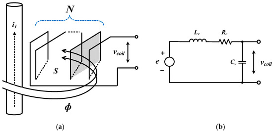
Figure 1.
Schematic diagram of a pick-up coil: (a) principle of a pick-up coil; (b) equivalent lumped circuit.
Further, the mutual inductance is obtained as defined in Equation (2). Here, µo is permeability of free space, which equals 4π × 10−7 H/m, N is the turn number of the coil, and S is the inner area of the core through which the magnetic flux passes. The mutual inductance is proportional to the number of turns, and the measurement sensitivity is determined accordingly.
Moreover, when the primary current i1 flows into the coil circuit, the coil can be equalized using a lumped model, as illustrated in Figure 1b, where the coil-induced voltage is expressed as follows:
where Lc is the magnetization inductance of the coil, Rc is the self-resistance value of the coil, Cc is the self-capacitance value of the coil.
2.2. Pickup Coil Model Built in PCB
In the PCB model of the existing pick-up coil [30], the sensor coil is a vertical structure on the conductor trace where the current flows; moreover, the sensor coil is composed of trace lines and vias, and is configured to transfer the magnetic flux generated by the primary current inside the coil in Figure 2.
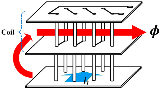
Figure 2.
Conventional printed circuit board (PCB) pick-up coil design.
Figure 3 shows the vector distribution of the magnetic flux density between the sensor and the conductor when a conductor current of 5A flows through a conventional pick-up coil. In this case, when the current flows through vias, the number of vias increases as the turn numbers of the coil increases, which can result in PCB overheating and an increase in loop impedance owing to uneven distribution and the bottleneck of the current flowing on the PCB [31]. Thus, as the number of turns of the coil increases, the self-inductance and sensitivity of the coil increases.
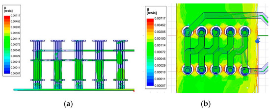
Figure 3.
PCB circuit analysis using finite element method: (a) side view; (b) top view.
In this study, the groups of pick-up coils according to their shapes include fishbone, saw blade, triangle-shaped, and rectangle-shaped types. The number of turns and shape of the coils were adjusted during the design stage such that the same mutual inductance value is achieved between the conductor through which the primary current flows and the coil. The values of the different parameters are listed in Table 1. Moreover, the PCB configuration according to the shape of the coil and inductance values obtained by the finite element method were compared and analyzed.

Table 1.
Comparison of the dependent coil structure.
Current sensors used in GaN devices are required to simultaneously secure high sensitivity and bandwidth. Because the bandwidth (BW) of the coil is significantly influenced by the self-inductance value of the coil as seen (4), the coil must have a minimum self-inductance value Lc to ensure sufficient bandwidth. Further, the coil must have high sensor sensitivity because it is configured to allow maximum magnetic flux inside the core. From Figure 4a, it can be observed that the bandwidth for the same value of mutual inductance with the conductor are in the order of fishbone type > saw blade type > triangle type > rectangle type for each model. With the same self-inductance criterion, the sensitivity of the sensor appeared in reverse order in Figure 4b. Therefore, when designing a sensor coil based on a specific sensitivity, a rectangular coil model representing the widest bandwidth can be selected.
where fres is the resonant frequency of sensor and fc is the cutoff frequency of sensor.
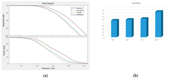
Figure 4.
Comparison between pick-up coils without integrator: (a) frequency response of sensor coil at M = 1.15 nH; (b) coil sensitivity at Ls = 19 nH.
3. Design of the Proposed Pick-Up Coil
3.1. Basic Structure of the Rectangular Pick-Up Coil
The proposed coil is in the form of two turns of the rectangular shape on a two-layer design; moreover, the trace through which the primary current flows wraps the sensor coil on three sides. The width of the coil trace is 0.4 mm, and the spacing between the coil and the trace through which the primary current on the three sides flows is 0.17 mm as shown in Figure 5a.
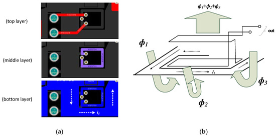
Figure 5.
Proposed sensor coil structure: (a) description of the proposed coil; (b) PCB layout.
Accordingly, the magnetic flux component on the three sides due to the primary current flowing in the plane of the bottom layer flows into the coil in the same direction and maximizes the mutual inductance value of the pick-up coil, ultimately increasing the sensor sensitivity, as shown in Figure 5b.
Figure 6a shows the direction of current and Figure 6b,c illustrate the distribution of the magnetic field between the sensor and the conductor when a 5 A conductor current flows in the proposed double-layer rectangle sensor model. In the figure, the arrow indicates the direction of the current, and the magnetic field diagram shows the magnetic flux density value according to the distance between the coil and the conductor on three sides.
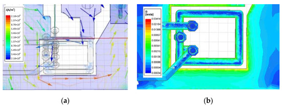
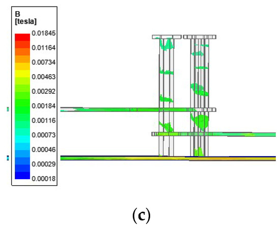
Figure 6.
PCB circuit analysis using finite element method: (a) current flow of 5×100 A; (b) top view of magnetic flux density; (c) side view of magnetic flux density.
3.2. Single-layer Rectangular Pick-Up Coil
Figure 7b shows the geometry of the single coil based on the lump equivalent circuit of a ℼ model, as shown in Figure 7a, where a is the distance from the trace through which the primary current flows to the coil, and w is the width of the coil. Thus, when the magnetic field flux formed by the current passes through area S, the magnetic flux in the area is calculated as follows.
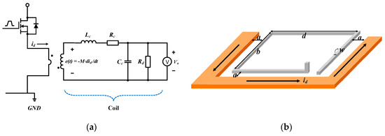
Figure 7.
Proposed pick-up coil model: (a) equivalent ℼ model; (b) geometry of a single coil.
When this magnetic flux enters the sensor core, the EMF in the terminal of the sensor coil loop is defined according to Faraday’s law as follows.
In addition, the magnetic flux formed by the current trace on the three sides enters in the same direction and same area in the sensor coil and penetrates the coil. The generated magnetic flux is calculated as shown below:
Thus, the EMF induced by the magnetic flux passing through the coil area is calculated according to Faraday’s law as follows:
From Equations (6) and (8), the mutual inductance of the coil is formulated as:
When the current of frequency f flows in a conductor, the skin depth at the conductor surface is calculated as follows, where γ represents the conductivity of the conductor:
3.3. Multilayer Rectangular Pick-Up Coil
The proposed model is composed of two single coils in series, as shown in Figure 8. The coils of each layer have a self-inductance value of Ln, and each coil forms a mutual inductance with the other. Here, m12 represents the mutual inductance value between the first layer and the second layer. Moreover, the direction of the coil current of each layer is connected in series, as illustrated in Figure 5a; therefore, the inductance of the entire coil is a value obtained by adding the self-inductance and mutual inductance components in each layer. As a parameter for the dynamic performance analysis of the multi-coil, the total inductance is calculated using Equation (12).
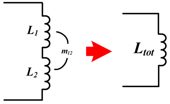
Figure 8.
Geometry of single rectangular coil.
The resistance of the multilayer coil is as shown below:
The mutual inductance m12 between single coils is calculated as follows [16] and [17]. Here, d denotes the distance between the single coils, l denotes the length of a single coil loop. Here, it is assumed that the self-inductance of the two coils is as shown below:
3.4. Parameter Selection for Sensor Design
The transfer function of the pick-up coil based in the lumped model at the initial condition is as shown below:
Here, the optimal damping resistance Rd is calculated using Equation (18), based on the damping ratio ζ [32].
Further, the resonance frequency is calculated as follows:
Two poles for coil design are formulated as presented below:
In the case of an integrator design, an active inverting integrator is applied [32,33,34,35], and a integrator resistor Rf and integrator capacitor Cf are added to the operational amplifier (OP-Amp) to limit the integrator infinite gain value to a finite gain value when a current of low frequency and the DC component flows in the integrator in Figure 9.
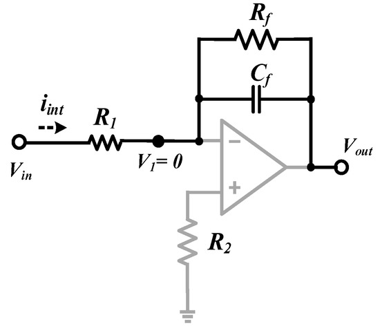
Figure 9.
Optimized integral circuit.
Moreover, the integrator current iint is calculated using the following equation:
Further, the input/output gain value is calculated according to the following equation:
where R1 is the reverse terminal resistance.
From the frequency response graph illustrated in Figure 10, it can be observed that when designing the integrator, the unit gain frequency fr is the value obtained by multiplying the cutoff frequency fc and the gain at the corner frequency using Equation (24) according to the gain bandwidth product.
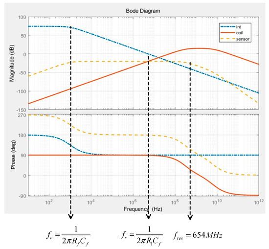
Figure 10.
Frequency response characteristics of the current sensor.
The non-inverting terminal resistance R2 located in the OP-Amp terminal constitutes the integrator, inverted and noninverted terminal resistors to minimize bias current error and is set to the same value (25).
Figure 10 shows the frequency response of the coil, integrator, and all the sensors. Sufficient sensor bandwidth must be secured for accurate transient response analysis when measuring the current for high-speed GaN power semiconductors. Thus, it is necessary to set the appropriate parameter values for the integrator and pick-up coil and to correspondingly adjust the pole values in the magnitude-frequency response of the sensor.
The GaN device used in this study was GS66508T, which is manufactured by GaN Systems; moreover, the device resonant frequency fres that was calculated based on Equation (19) at a current increase time of 1.5 ns was determined to be 220 MHz.
Accordingly, the sensor bandwidth for ensuring accurate measurement results must be secured to a value that is at least two to three times the value of the bandwidth of the power semiconductor [31]. Therefore, when the integrator cutoff frequency is set to 1 kHz, it is possible to guarantee a sensor bandwidth of over 440 MHz. Further, the transfer function of the current sensor with the integrated sensor coil and integrator is obtained as follows.
Moreover, the measurement sensitivity is obtained as shown below:
In this case, assuming Rd ≫ Rc, the sensor measurement sensitivity can be calculated as follows:
In Equation (29), the sensitivity of the sensor is expressed as a product of the unit gain frequency value of the integrator and the mutual inductance value between the trace through which the primary current flows and the pick-up coil. Thus, the sensitivity and bandwidth of the sensor are simultaneously affected by the parameter values of the coil inductance and integrator; consequently, careful parameter selection is required when designing the sensor.
4. Experimental Verification
Figure 11a,b shows the shunt resistor sensor and the daughter board prototype of the double pulse test circuit. In the case of the switch current, the integrator output of the pick-up coil was compared with the results of the shunt resistor, and the load current was measured using a current sensor (LeCroy) with a maximum current of 310 A and 0.1 V/A output gain ratio. The prototype has two switches and a double-layer pick-up coil to measure the lower switch current in the half-bridge structure. The main and daughter boards are connected vertically through a connector head; Figure 11c shows the overall double pulse test set including an active integrator, digital signal processor board, inductor, main board, and daughter board. Table 2 lists the parameter values of the proposed coil and integrator.
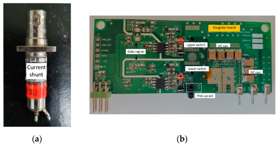
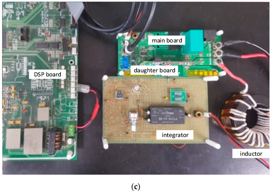
Figure 11.
Prototype board of double pulse test: (a) current shunt; (b) daughter board with pick-up coil; (c) overall double pulse test board.

Table 2.
Circuit parameters of current sensor.
Figure 12 shows the output waveform of the current shunt and pick-up coil before and after the switching operation. In Figure 12b, during the switch-off operation, the positive peak output value is +5.4 V. Conversely, during the switch-on operation, the positive peak output value is +1.94 V.
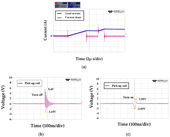
Figure 12.
Measured current shunt results and coil output without the integrator following switch behavior: (a) current shunt; (b) output of pick-up coil during switch-off condition; (c) output of pick-up coil during switch-on condition.
Figure 13 compares the integrator output value of the proposed coil with the sensor result of the 100 mΩ coaxial shunt resistor, manufactured by T&M Research Products, to compare the transient state of the switch current when the switching operation changes in a DC voltage environment of 100 V. In the switch-off stage, the result of the pick-up coil shows a peak value of approximately 1.6 V when compared to the result of the shunt resistor. This is the influence of the high dv/dt of the wide bandgap device; further, the influence of other factors such as the coupling capacitance between the coil and the conductor is reflected. In the switch-on section, the waveform in the switching operation is at a similar level as the waveforms in the two sensors.

Figure 13.
Measured pick-up coil sensor output following switch behavior when the DC link voltage is 100 V: (a) switch turn-off; (b) switch turn-on.
Figure 14 presents the results for a DC voltage environment of 250 V. Overall, the integrator output value of the pick-up coil in the transient response section shows a waveform similar to that of the shunt resistor sensor when compared to the case of a DC link voltage of 100 V. And the result in the switch-on section is more accurate than that in the switch-off section. However, the occurrence of a positive peak value in the switch-off section indicates the same result as in the case of the 100 V DC link voltage.
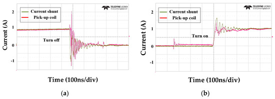
Figure 14.
Measured pick-up coil sensor output following switch behavior for a DC link voltage of 250 V: (a) switch turn-off; (b) switch turn-on.
5. Conclusions
In this study, a pick-up coil, which is a current sensor for measuring the switch current of a half-bridge based on a non-modular GaN power semiconductor, was proposed. The proposed coil sensor measures the lower switch current at the bottom of the half-bridge; moreover, the structural characteristic includes a trace wrapped around a rectangular sensor coil composed of a 4.2 mm × 3.4 mm double layer on three sides through which the primary current to be measured flows. This structure aims to secure the maximum bandwidth and achieve high measurement sensitivity for the GaN device with fast switching characteristics.
This was confirmed through inductance comparison analysis with the conventional coil structure using the finite element method as well as frequency response analysis through mathematical modeling based on parameter values. Moreover, experimental verification was conducted using the double pulse test through an analysis process for the transient situation for switch-on and switch-off conditions in a DC voltage environment ranging from 100 to 250 V. However, this paper did not consider the issue of the coupling capacitance noise between the coil and the conductor, and accordingly, some overshoot components were seen in the switch-off condition, which appeared in the experimental results. In the future, further studies on reinforcement of this issue and discussion on solutions are needed.
Author Contributions
Conceptualization, U.-J.K. and R.-Y.K.; methodology, U.-J.K.; software, M.-S.S., U.-J.K.; validation, U.-J.K.; formal analysis, U.-J.K. and M.-S.S.; investigation, U.-J.K.; resources, U.-J.K.; data curation, U.-J.K.; writing—original draft preparation, U.-J.K.; writing—review and editing, U.-J.K. and R.-Y.K.; visualization, U.-J.K.; supervision, U.-J.K.; project administration, R.-Y.K.; funding acquisition, R.-Y.K. All authors have read and agreed to the published version of the manuscript.
Funding
This research was funded by Korea Institute of Energy Technology Evaluation and Planning grant number 2018201010650A, 20184010201710.
Conflicts of Interest
The authors declare no conflict of interest.
References
- Sandler, S. Faster-Switching GaN: Presenting a number of interesting measurement challenges. IEEE Power Electron. Mag. 2015, 2, 24–31. [Google Scholar] [CrossRef]
- Lidow, A.; De Rooij, M.; Strydom, J.; Reusch, D.; Glaser, J. GaN Transistors for Efficient Power Conversion; Wiley: Hoboken, NJ, USA, 2019. [Google Scholar]
- Iwaki, T.; Ishiwaki, S.; Sawada, T.; Yamamoto, M. An analysis of false turn-on phenomenon of GaN HEMT with parasitic components. In Proceedings of the 2017 IEEE International Telecommunications Energy Conference (INTELEC), Broadbeach, QLD, Australia, 22–26 October 2017; pp. 347–350. [Google Scholar]
- Vitanov, S.; Palankovski, V.; Maroldt, S.; Quay, R. High-temperature modeling of AlGaN/GaN HEMTs. Solid-State Electron. 2010, 54, 1105–1112. [Google Scholar] [CrossRef]
- Wang, K.; Yang, X.; Wang, L.; Jain, P. Instability analysis and oscillation suppression of enhancement-mode GaN devices in half-bridge circuits. IEEE Trans. Power Electron. 2018, 33, 1585–1596. [Google Scholar] [CrossRef]
- Li, K.; Videt, A.; Idir, N. Using current surface probe to measure the current of the fast power semiconductors. IEEE Trans. Power Electron. 2014, 30, 2911–2917. [Google Scholar] [CrossRef]
- Danilovic, M.; Chen, Z.; Wang, R.; Luo, F.; Boroyevich, D.; Mattavelli, P. Evaluation of the switching characteristics of a gallium-nitride transistor. In Proceedings of the 2011 IEEE Energy Conversion Congress and Exposition, Phoenix, AZ, USA, 17–22 September 2011; pp. 2681–2688. [Google Scholar]
- Pacha, M.; Varecha, P.; Sumega, M. HW issues of current sensing by DC-link shunt resistor. In Proceedings of the 2018 ELEKTRO, Mikulov, Czech Republic, 21–23 May 2018; pp. 1–5. [Google Scholar] [CrossRef]
- Tiwari, S.; Midtgard, O.M.; Undeland, T.M. Experimental performance evaluation of two commercially available, 1.2 kV half-bridge SiC MOSFET modules. In Proceedings of the IECON 2016—42nd Annual Conference of the IEEE Industrial Electronics Society, Florence, Italy, 23–26 October 2016; pp. 1106–1111. [Google Scholar]
- Ferreira, J.; Cronje, W.; Relihan, W. Integration of high frequency current shunts in power electronic circuits. IEEE Trans. Power Electron. 1995, 10, 32–37. [Google Scholar] [CrossRef]
- Nibir, S.J.; Biglarbegian, M.; Parkhideh, B. A non-invasive DC-10-MHz wideband current sensor for ultra-fast current sensing in high-frequency power electronic converters. IEEE Trans. Power Electron. 2019, 34, 9095–9104. [Google Scholar] [CrossRef]
- Singh, R.P.; Khambadkone, A.M. Giant magneto resistive (GMR) effect based current sensing technique for low voltage/high current voltage regulator modules. IEEE Trans. Power Electron. 2008, 23, 915–925. [Google Scholar] [CrossRef]
- Parkhideh, B.; Nibir, S.J. Hybrid magnetoresistor-planar Rogowski current sensing scheme with folded trace magnetic field concentration technique. IEEE Sens. J. 2017, 17, 1. [Google Scholar] [CrossRef]
- Dalessandro, L.; Karrer, N.; Kolar, J.W. High-performance planar isolated current sensor for power electronics applications. IEEE Trans. Power Electron. 2007, 22, 1682–1692. [Google Scholar] [CrossRef]
- Ziegler, S.; Woodward, R.C.; Iu, H.H.C.; Borle, L.J. Current sensing techniques: A review. IEEE Sens. J. 2009, 9, 354–376. [Google Scholar] [CrossRef]
- Rosa, E.B. Calculation of the self-inductance of single-layer coils. Bull. Bur. Stand. 1906, 2, 161. [Google Scholar] [CrossRef]
- Mills, M.K. Inductive loop system equivalent circuit model. In Proceedings of the IEEE 39th Vehicular Technology Conference, San Francisco, CA, USA, 1–3 May 1989. [Google Scholar]
- Zhu, M.; Perreault, D.; Caliskan, V.; Neugebauer, T.; Guttowski, S.; Kassakian, J. Design and evaluation of feedforward active ripple filters. IEEE Trans. Power Electron. 2005, 20, 276–285. [Google Scholar] [CrossRef]
- Round, S.; Heldwein, M.; Kolář, J.; Hofsajer, I.; Friedrichs, P. A SiC JFET driver for a 5 kW, 150 kHz three-phase PWM converter. In Proceedings of the Fourtieth IAS Annual Meeting, Conference Record of the 2005 Industry Applications Conference, 2005, Kowloon, Hong Kong, China, 2–6 October 2005. [Google Scholar]
- Wang, J.; Shen, Z.; Burgos, R.; Boroyevich, D. Design of a high-bandwidth Rogowski current sensor for gate-drive shortcircuit protection of 1.7 kV SiC MOSFET power modules. In Proceedings of the 2015 IEEE 3rd Workshop on Wide Bandgap Power Devices and Applications (WiPDA), Blacksburg, VA, USA, 2–4 November 2015; pp. 104–107. [Google Scholar]
- Samimi, M.H.; Mahari, A.; Farahnakian, M.A.; Mohseni, H. The Rogowski coil principles and applications: A review. IEEE Sens. J. 2014, 15, 651–658. [Google Scholar] [CrossRef]
- Shafiq, M.; Kutt, L.; Lehtonen, M.; Nieminen, T.; Hashmi, M. Parameters identification and modeling of high-frequency current transducer for partial discharge measurements. IEEE Sens. J. 2012, 13, 1081–1091. [Google Scholar] [CrossRef]
- Robles, G.; Argüeso, M.; Sanz-Feito, J.; Giannetti, R.; Tellini, B. Identification of parameters in a Rogowski coil used for the measurement of partial discharges. In Proceedings of the 2007 IEEE Instrumentation & Measurement Technology Conference IMTC 2007, Warsaw, Poland, 1–3 May 2007; pp. 1–4. [Google Scholar]
- Zhang, Y.; Liu, J.; Bai, G.; Feng, J. Analysis of damping resistor’s effects on pulse response of self-integrating Rogowski coil with magnetic core. Measurement 2012, 45, 1277–1285. [Google Scholar] [CrossRef]
- Jiao, C.; Zhang, J.; Zhao, Z.; Zhang, Z.; Fan, Y. Research on small square PCB Rogowski coil measuring transient current in the power electronics devices. Sensors 2019, 19, 4176. [Google Scholar] [CrossRef]
- Tao, T.; Zhao, Z.; Ma, W.; Pan, Q.; Hu, A. design of PCB Rogowski coil and analysis of anti-interference property. IEEE Trans. Electromagn. Compat. 2016, 58, 344–355. [Google Scholar] [CrossRef]
- Bortis, D.; Biela, J.; Kolar, J. Active gate control for current balancing of parallel-connected IGBT modules in solid-state modulators. IEEE Trans. Plasma Sci. 2008, 36, 2632–2637. [Google Scholar] [CrossRef]
- Tsukuda, M.; Koga, M.; Nakashima, K.; Omura, I. Micro PCB Rogowski coil for current monitoring and protection of high voltage power modules. Microelectron. Reliab. 2016, 64, 479–483. [Google Scholar] [CrossRef]
- Zhao, L.; Van Wyk, J.; Odendaal, W. Planar embedded pick-up coil sensor for integrated power electronic modules. In Proceedings of the Nineteenth Annual IEEE Applied Power Electronics Conference and Exposition, 2004, APEC ’04, Anaheim, CA, USA, 22–26 February 2004. [Google Scholar]
- Xue, Y.; Lu, J.; Wang, Z.; Tolbert, L.M.; Blalock, B.J.; Wang, F. A compact planar Rogowski coil current sensor for active current balancing of parallel-connected Silicon Carbide MOSFETs. In Proceedings of the 2014 IEEE Energy Conversion Congress and Exposition (ECCE), Pittsburgh, PA, USA, 14–18 September 2014; pp. 4685–4690. [Google Scholar] [CrossRef]
- Wang, K.; Yang, X.; Li, H.; Wang, L.; Jain, P. A high-bandwidth integrated current measurement for detecting switching current of fast GaN devices. IEEE Trans. Power Electron. 2018, 33, 6199–6210. [Google Scholar] [CrossRef]
- Ray, W.F. Rogowski transducers for high bandwidth high current measurement. In Proceedings of the IEE Colloquium on Low Frequency Power Measurement and Analysis (Digest No. 1994/203), London, UK, 2 November 1994. [Google Scholar]
- Ray, W.; Hewson, C. High performance Rogowski current transducers. In Proceedings of the Conference Record of the 2000 IEEE Industry Applications Conference. Thirty-Fifth IAS Annual Meeting and World Conference on Industrial Applications of Electrical Energy (Cat. No.00CH37129), Rome, Italy, 8–12 October 2002. [Google Scholar] [CrossRef]
- Li, W.; Yin, X.; Chen, D.; Chen, W.; Zhang, Z.; Xia, Y. The Study of Transient Performance of Current Sensor Based on Rogowski Coil and Its Application in Dynamic Simulation Experiment. In Proceedings of the 2006 International Conference on Power System Technology, Institute of Electrical and Electronics Engineers (IEEE), Chongqing, China, 22–26 October 2006; pp. 1–6. [Google Scholar]
- Liu, Y.; Lin, F.; Zhang, Q.; Zhong, H. Design and construction of a Rogowski coil for measuring wide pulsed current. IEEE Sens. J. 2010, 11, 123–130. [Google Scholar] [CrossRef]
© 2020 by the authors. Licensee MDPI, Basel, Switzerland. This article is an open access article distributed under the terms and conditions of the Creative Commons Attribution (CC BY) license (http://creativecommons.org/licenses/by/4.0/).


