Article

A Method to Improve Torque Density in a Flux-Switching Permanent Magnet Machine

1
College of Information Science and Engineering, Huaqiao University, Xiamen 361021, China
2
Department of Electrical Engineering, The Hong Kong Polytechnic University, Hong Kong 999077, China
*
Author to whom correspondence should be addressed.
Energies 2020, 13(20), 5308; https://doi.org/10.3390/en13205308
Submission received: 9 August 2020 / Revised: 6 October 2020 / Accepted: 10 October 2020 / Published: 13 October 2020
(This article belongs to the Special Issue Magnetic Material Modelling of Electrical Machines)

Abstract

:
With the continuous development of machines, various structures emerge endlessly. In this paper, a novel 6-stator-coils/17-rotor-teeth (6/17) E-shaped stator tooth flux switching permanent magnet (FSPM) machine is introduced, which has magnets added in the dummy slots of the stator teeth. This proposed machine is parametrically designed and then compared with the conventional 6/17 E-shaped stator tooth FSPM machine through finite element method (FEM) analysis. Then, combined with the results of FEM, the performance of two machines is evaluated, such as electromagnetic torque, efficiency, back electromotive force (back-EMF). The final results show that this novel 6/17 FSPM machine has greater output torque and smaller torque ripple.

1. Introduction

Flux switching permanent magnet (FSPM) machines have gained wide application from aerospace to automobile industries since they offer several key advantages, such as a simple and robust rotor, short end winding, high torque density, high efficiency, and excellent flux-weakening capability. The flux switching permanent magnet machine has characteristics of a permanent magnet synchronous machine and a switched reluctance machine, which combines the merits of both. These advantages are particularly important for applications such as electric vehicles, wind power technologies, and flywheel systems. However, compared with the traditional motor, the torque density of a FSPM is low. In this paper, the existing structure is improved to enhance the torque density of a FSPM. After putting forward the operation principle of the FSPM machine, many kinds of its topologies have been studied [1,2,3,4,5,6]. Among them, the E-shaped stator tooth FSPM machine has a unique structure with two magnets mounted in each stator tooth, which makes it exhibit higher torque/magnetic ratio and larger torque [7].
In this paper, a novel 6/17 E-shaped stator tooth FSPM machine is studied for further improving the torque density. Compared with the conventional 6/17 E-shaped stator tooth FSPM machine, the proposed machine adds permanent magnets in the dummy slot of the stator teeth. In Section 3, the electromagnetic performance of the two machines is analyzed using the finite element method (FEM). Afterwards, the performance of the two machines is compared, according to back-EMF, electromagnetic torque, torque ripple, etc. Finally, the conclusions are drawn in Section 4.

2. Model of Machines

The structure of the conventional 6/17 E-shaped stator tooth FSPM machine can be seen in Figure 1. A dummy slot is inserted between two magnets that are embedded at the upper apex of a stator tooth, which can increase the torque of this machine and reduce torque ripple. However, it is worth noting that for the machine shown in Figure 1, dummy slots are empty. If permanent magnets are added into the dummy slots, the torque will be further improved. In addition, the armature coils of this structure are arranged in the form of A1–B1–C1–A2–B2–C2, and a phase winding is formed by every two coils connected in series, that is, A1 and A2 represent phase A [7]. Moreover, these coils are distributed radially along the space. At the same time, the magnetic polarities formed by magnets near the air gap maintain N–S–S–N.
As seen in Figure 2, a permanent magnet (PM) is added to each dummy slot of the stator tooth in the proposed structure, so that its effective PM volume increases. Therefore, compared with the initial structure, the output torque of this novel 6/17 E-shaped stator tooth machine is greater.
For further contrasting the performance of the machine, the motor structure proposed in [7] is reproduced in this paper. Through ANSYS software modeling and parametric analysis, the conventional 6/17 E-shaped stator tooth FSPM machine with the same structure and performance as the machine proposed in [7] is obtained.
This parametric design process mainly focuses on the shape and size of initial permanent magnets, the width and depth of the opening of dummy slots, and the shape of rotor teeth; the optimization results are acquired by using ANSYS software. Then, their maximum average output torque is obtained under the same copper loss (69 w). If the end winding is neglected, copper loss will satisfied the following equation [8]:
P C u = 3 I a 2 R a = 6 I a 2 N a 2 ρ C u L a S a k p f
where Na is the number of coil turns per phase, Ra is the phase resistance, La is the stack length, Sa is the stator slot area, kpf is the winding packing factor, Ia is the RMS phase current, and ρ Cu is the electrical resistivity of copper at 20 °C.
To analyze the performance of the two 6/17 E-shaped stator tooth FSPM machines, FEM is carried out by using ANSYS software. Based on the initial structure, permanent magnets with radial magnetization are added in the dummy slot. The thickness of the newly added permanent magnet, h in Figure 2, is parametrically designed and simulated.
As shown in Figure 3, when the current density is 5 A/mm2, average torque and torque ripple of the proposed machine vary with the thickness of the permanent magnet. Figure 3a shows that the torque of the proposed machine is positively proportional to h, and the inflection point is around 3 mm. After 3 mm, the thickness of permanent magnet increases, but the average torque almost does not change. It can be observed from Figure 3a that torque ripple is inversely proportional to h, basically. Meanwhile, the inflection point is at 4 mm, and the torque ripple does not change after 4 mm; thus, the final value of h is 4 mm. In this case, the average torque is the largest and torque ripple is the smallest, while the amount of permanent magnets is the least. Excessive use of permanent magnets will increase the cost of manufacture and the iron loss. Table 1 shows their main specifications and parameters.

3. Performance Comparisons

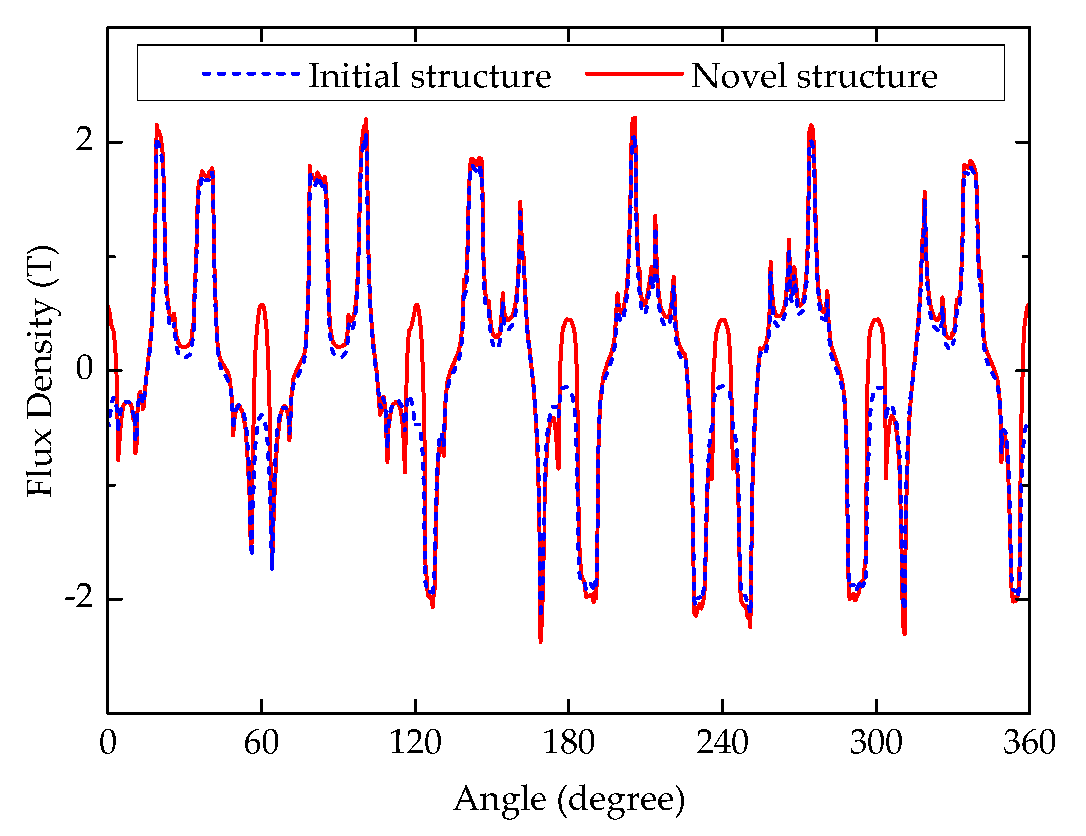
3.1. No-Load Performance

Meanwhile, it can be distinguished from Figure 4 that the no-load magnetic field distributions of the novel structure are different from the initial structure. Additionally, in the structure of the proposed machine, the magnetic flux density of its stator is somewhat greater than that of the conventional structure. In Figure 4, from the circled part, nine magnetic lines on Figure 4a and 10 lines on Figure 4b can be seen. It can be observed that the flux density in Figure 4b is higher. As shown in Figure 4a, there is no flux distribution in the dummy slot, but, magnetic lines of magnetization direction are added in the dummy slot for Figure 4b. This is because permanent magnets are increased in the dummy slots of the proposed structure. It can be observed from Figure 4 that the distortion of the magnetic lines of force is also reduced with the increased permanent magnet. The higher the magnetic density at the stator, the greater the torque that can be produced under the same current.
The distribution of no-load air-gap flux density in two E-shaped stator tooth FSPM machines is implied by Figure 5. It can be observed that the proposed machine has a larger air-gap flux density, which indicates the proposed structure can produce a much larger output torque than the initial one.
At the same time, peak-to-peak value of cogging torque of the proposed machine (0.54 Nm) is higher than that of the initial machine (0.33 Nm), as shown in Figure 6. Additionally, the energy in the air gap is related to cogging torque, so the formula for calculating the cogging torque [9] can be written as:
T c o g = W θ r = θ r ( 1 2 μ 0 B 2 d V )
where W is the energy in the air gap, B is the air-gap flux density, μ0 is the magnetic permeability of the free space, and V is the volume of air gap. Meanwhile, this novel 6/17 E-shaped stator tooth FSPM has both a higher air-gap flux density and a larger cogging torque due to the magnets in the dummy slots of the stator tooth.
Next, Figure 7 shows the no-load back-EMF waveforms of the two machines at 1500 r/min that were computed by finite element method (FEM). Results indicate that the two waveforms are symmetrical; in addition, with respect to the amplitude back-EMF, the proposed E-shaped stator tooth machine shows a larger amplitude back-EMF because of larger fluxes flowing through the coil. Meanwhile, Figure 8 indicates the fast Fourier transform (FFT) results of back-EMF waveforms.
After adding magnets in the dummy slots of the stator teeth, the amplitude of fundamental back-EMFs is enhanced. It can be observed from Figure 8 that the third, fifth, and seventh components harmonics of on-load back-EMF are reduced greatly after adding magnets. Then, with magnets located in the dummy slots, the fundamental harmonic of on-load back-EMF is enhanced from 176.1 to 200.6 V. The total harmonic distribution (THD) of initial and proposed E-shaped stator tooth machines is 5.7% and 4.7%, respectively, and there is no additional extra harmonic introduced into the targeted on-load back-EMF.

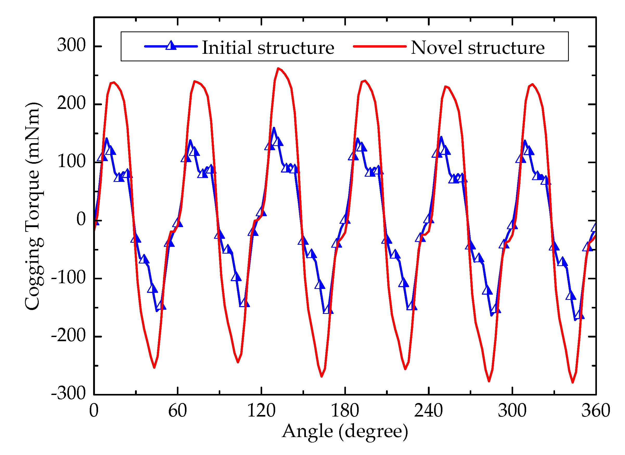
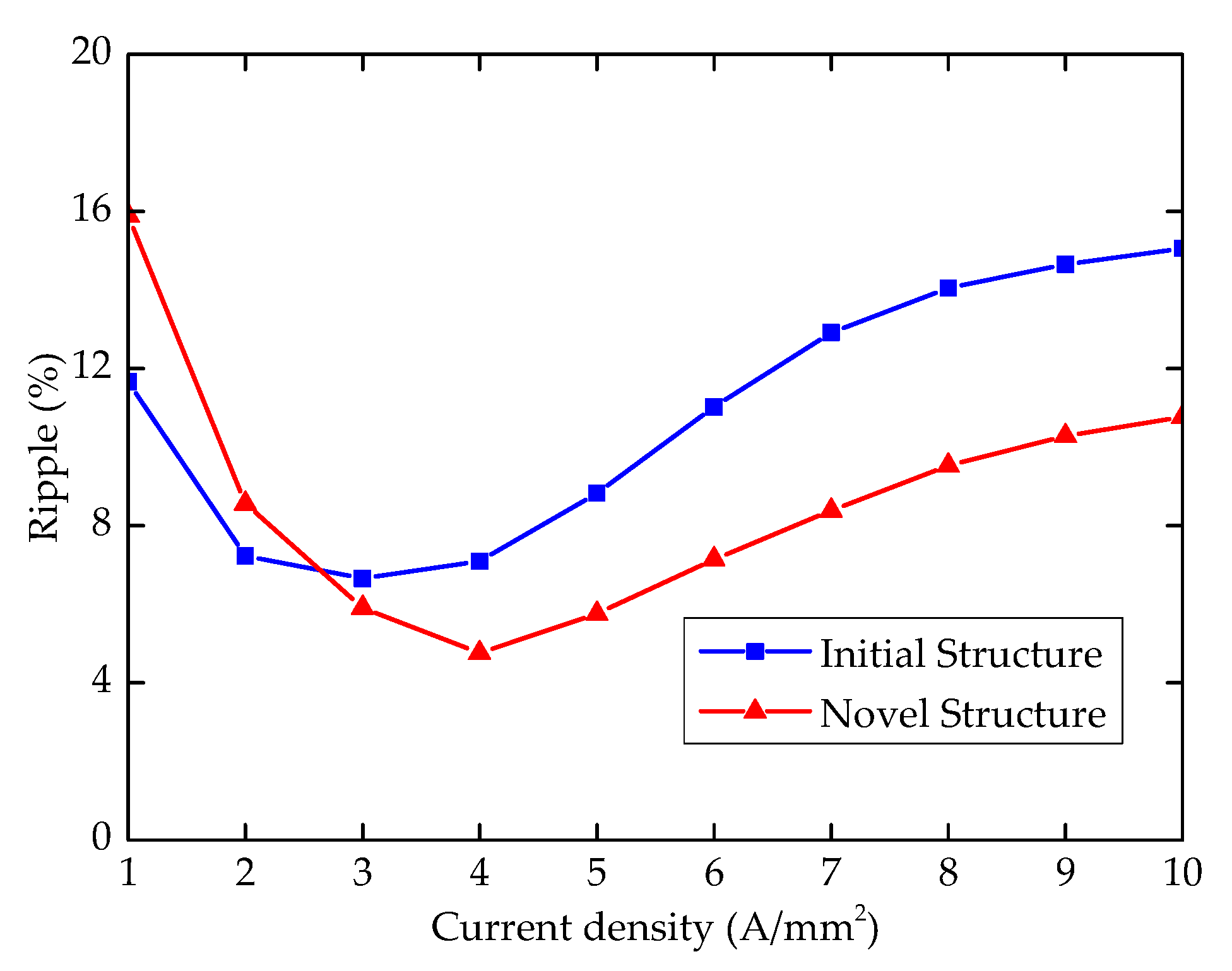
3.2. Torque Performance

Figure 9 and Figure 10 indicate that the two machines are controlled by id = 0 mode, where the current density ranges from 1 to 10 A/mm2, while the stator coil turns and the slot packing factor is 73 and 0.45, respectively [8]. Results imply that under 10 A/mm2, the average torque of the proposed structure is significantly greater than that of the initial structure. As far as torque ripple is concerned, the proposed machine is also somewhat smaller than the E-shaped stator tooth structure above 2 A/mm2, after adding the magnets in the dummy slots of stator teeth. The average torque of the proposed machine (15.38 Nm) is greater than that of the conventional one (13.04 Nm) at the rated current density (5 A/mm2).
The torque ripple of the novel machine (5.7%), however, is a little lower. Under the condition of low torque ripple, the proposed machine needs to be further optimized through adopting some strategies to make the torque ripple smaller [5,10,11]; at the same time, the average torque will also be reduced. Figure 11 indicates the electromagnetic torque waveforms of these two machines.
Table 2 shows comparative results of the two E-shaped stator tooth FSPM machines. It can be found that they both have the same machine volume, but the ratio of torque to the volume of the proposed machine is larger. More importantly, the average torque of the machines is 13.04 Nm and 15.38 Nm, respectively; thus, the average torque of the proposed machine is 20% higher. In other words, torque density is hugely enhanced for the proposed machine. Meanwhile, the torque ripple of the two machines is 5.7% and 8.8%, respectively, and that of the proposed machine is reduced by 3.1%. This is because the new structure increases the radial permanent magnet and enhances flux density distribution in the air gap, so the cogging torque and torque ripple are reduced. Besides, when the two machines both work under 1500 r/min and 5 A/mm2, their efficiency is approximately equal, 0.877 and 0.897. The amount of permanent magnets increases by 21%, which improves the performance of the motor, and the cost of permanent magnet is only a small part of the manufacturing cost of the motor. Therefore, it is worthwhile to increase the permanent magnets.

4. Conclusions

In summary, this paper introduces a novel 6/17 E-shaped stator tooth FSPM machine with an added magnet in the upper apex of each dummy slot, which is derived from the conventional 6/17 E-shaped stator tooth FSPM machine. Then, two kinds of 6/17 E-shaped stator tooth FSPM machine topologies with the same rotor tooth are compared by FEM. Finally, the electromagnetic performance of the two kinds of E-shaped stator tooth machine is compared, while final results indicate that the proposed E-shaped stator tooth machine has higher torque, back-EMF, and efficiency than the initial machine. In addition, the proposed structure has a lower torque ripple and lower THD of phase back-EMF. Therefore, this proposed E-shaped stator tooth machine has a better performance.

Author Contributions

Conceptualization, J.C. and X.G.; methodology, W.F.; software, J.C.; validation, J.C., Y.L. and X.G.; formal analysis, J.C.; investigation, J.C.; resources, X.G.; data curation, J.C.; writing—original draft preparation, R.W.; writing—review and editing, L.L.; visualization, J.C.; supervision, W.F.; project administration, X.G.; funding acquisition, X.G. All authors have read and agreed to the published version of the manuscript.

Funding

This work was supported by the Xiamen Science and Technology Project—University Research Institute Industry–University–Research Project—under Grant 3502Z202003037, and in part by the Subsidized Project for Postgraduates’ Innovative Fund in Scientific Research of Huaqiao University under Grant 18014082018.

Conflicts of Interest

The authors declare no conflict of interest.

References

  1. Hoang, E.; Ahmed, B.; Lucidarme, J. Switching flux permanent magnet polyphased synchronous machines. In Proceedings of the European Conference Power Electrinics and Applications, Trondheim, Norway, 8–10 September 1997; pp. 903–908. [Google Scholar]
  2. Wu, Z.Z.; Zhu, Z.Q. Analysis of air-gap field modulation and magnetic gearing effects in switched flux permanent magnet machines. IEEE Trans. Magn. 2015, 51, 1–12. [Google Scholar] [CrossRef]
  3. Hua, W.; Cheng, M.; Zhu, Z.Q.; Howe, D. Analysis and optimization of back EMF waveform of a flux-switching permanent magnet motor. IEEE Trans. Energy Convers. 2008, 23, 727–733. [Google Scholar] [CrossRef]
  4. Chen, J.T.; Zhu, Z.Q. Winding configurations and optimal stator and rotor pole combination of flux-switching PM brushless AC machines. IEEE Trans. Energy Convers. 2010, 25, 293–302. [Google Scholar] [CrossRef]
  5. Xiang, Z.; Zhu, X.; Quan, L.; Du, Y.; Zhang, C.; Fan, D. Multilevel design optimization and operation of a brushless double mechanical port flux-switching permanent-magnet motor. IEEE Trans. Ind. Electron. 2016, 63, 6042–6054. [Google Scholar] [CrossRef]
  6. Zhou, Y.J.; Zhu, Z.Q. Torque density and magnet usage efficiency enhancement of sandwiched switched flux permanent magnet machines using V-shaped magnets. IEEE Trans. Magn. 2013, 49, 3834–3837. [Google Scholar] [CrossRef]
  7. Zhao, G.; Hua, W. Comparative study between a novel multi-tooth and a V-shaped flux-switching permanent magnet machines. IEEE Trans. Magn. 2019, 55, 1–8. [Google Scholar] [CrossRef]
  8. Guo, X.; Wu, S.; Fu, W.N.; Liu, Y.; Wang, Y.; Zeng, P. Control of a dual-stator flux-modulated motor for electric vehicles. Energies 2016, 9, 517. [Google Scholar] [CrossRef] [Green Version]
  9. Guo, X.; Wang, Q.; Shang, R.; Chen, F.; Fu, W.; Hua, W. Design and analysis of a novel synthetic slot dual-PM machine. IEEE Access 2019, 7, 29916–29923. [Google Scholar] [CrossRef]
  10. Zhu, X.; Hua, W.; Cheng, M. Cogging torque minimization in flux-switching permanent magnet machines by tooth chamfering. In Proceedings of the IEEE Energy Conversion Congress and Exposition, Milwaukee, WI, USA, 18–22 September 2016; pp. 1–7. [Google Scholar]
  11. Zhu, X.; Hua, W.; Wu, Z.; Huang, W.; Zhang, H.; Cheng, M. Analytical approach for cogging torque reduction in flux-switching permanent magnet machines based on magnetomotive force-permeance model. IEEE Trans. Ind. Electron. 2018, 65, 1965–1979. [Google Scholar] [CrossRef]
Figure 1. Conventional 6/17 E-shaped stator tooth flux switching permanent magnet (FSPM) machine: (a) conventional 6/17 FSPM machine; (b) partial enlarged.
Energies 13 05308 g001
Figure 2. Proposed 6/17 E-shaped stator tooth FSPM machine: (a) proposed 6/17 FSPM machine; (b) partial enlarged.
Energies 13 05308 g002
Figure 3. The results of parameterization: (a) relationship between average torque and h; (b) relationship between torque ripple and h.
Energies 13 05308 g003
Figure 4. No-load magnetic flux distributions of two FSPM machines: (a) conventional 6/17 FSPM machine; (b) proposed 6/17 FSPM machine.
Energies 13 05308 g004
Figure 5. No-load air-gap flux density distributions for the two FSPM machines.
Energies 13 05308 g005
Figure 6. Cogging torque waveforms of the two FSPM machines.
Energies 13 05308 g006
Figure 7. No-load back-EMFs of the two FSPM machines.
Energies 13 05308 g007
Figure 8. Fast Fourier transform (FFT) results of back-EMFs of the two FSPM machines.
Energies 13 05308 g008
Figure 9. Average torque waveforms versus the current density.
Energies 13 05308 g009
Figure 10. Torque ripple waveforms versus the current density.
Energies 13 05308 g010
Figure 11. Electromagnetic torque waveforms under J = 5 A/mm2.
Energies 13 05308 g011
Table 1. Design parameters of two FSPM machines.
ItemsInitialNovel
Stator coils number66
Rotor teeth number1717
Stack length (mm)7575
Stator outer diameter (mm)130130
Stator inner diameter (mm)7070
Air-gap length (mm)0.350.35
Slot package factor (kpf)0.450.45
Machine volume (m3)9.95 × 10−49.95 × 10−4
Rated speed (r/min)15001500
Rated current density (A/mm2)55
PM typeN35SHN35SH
PM volume (mm3)63,90077,400
Remnant Br (T)1.21.2
Coercivity Hc (kA/m)909909
Stator slot area (mm2)408408
Coil turns7373
Coil number per phase22
Table 2. Comparative results of the two FSPM machines.
ItemsInitialNovel
Amplitude of fundamental phase back-EMF (V)176.1200.6
Total harmonic distribution (THD) of phase back-EMF5.7%4.7%
Average torque (Nm)13.0415.38
Torque ripple8.8%5.7%
Ratio of torque to machine volume (Nm/m3)13,16915,530
Efficiency at 5 A/mm2 and 1500 r/min0.8770.897

