Article

An Energy Efficient Message Dissemination Scheme in Platoon-Based Driving Systems

1
Department of Smart-car, Soonchunhyang University, 22 Soonchunhyang-ro, Shinchang-myeon, Asan-si, Chungcheongnam-do 31538, Korea
2
IoT Connectivity Standard Team, LG Electronics, 19, Yangjae-daero 11-gil, Seocho-gu, Seoul 06772, Korea
3
The School of Engineering, Korea University, 145 Anam-ro, Seongbuk-gu, Seoul 02841, Korea
*
Author to whom correspondence should be addressed.
Energies 2020, 13(15), 3940; https://doi.org/10.3390/en13153940
Submission received: 29 June 2020 / Revised: 25 July 2020 / Accepted: 27 July 2020 / Published: 1 August 2020
(This article belongs to the Section A1: Smart Grids and Microgrids)

Abstract

:
With the development of the convergence of IT and automotive technology, platoon-based driving systems are getting more attention and how to disseminate messages in the platoon is an important issue. In this paper, to enhance the energy efficiency and traffic throughput (e.g., average velocity) while meeting transmission deadlines, we propose an energy efficient message dissemination scheme (EMDS) in platoon-based driving systems, which also provides proper power control and relay selection. To find out the optimal policy to balance the probability of successful message dissemination and transmission power cost in EMDS, we formulate a Markov decision process (MDP) problem that considers the velocity of the vehicles in the platoon. To evaluate the performance of EMDS, we analyze the outage probability, the average velocity, and the expected power consumption using the discrete-time Markov chain (DTMC) model. Evaluation results demonstrate EMDS with the optimal policy improves the average velocity and the energy efficiency of message dissemination compared with the conventional message dissemination schemes, while reducing the message dissemination failure rate.

Graphical Abstract

1. Introduction

Platooning is a method for driving a group of autonomous/semi-autonomous vehicles together in which the vehicles move in a train-like manner [1]. In platoon, a non-leader vehicle of the group maintains a small distance with the preceding vehicle to reduce fuel consumption by reducing the air drag and achieve efficient transport [2]. In addition, with the platoon-based driving, the adherence between vehicles can increase road capacity and reduce traffic congestion.
The objective of platoon-based driving is to ensure that all vehicles in a platoon move at the same velocity while maintaining a desired formation geometry according to a desired inter-vehicle spacing policy. To enable this, an important technology has been introduced in the past decade, autonomous cruise control (ACC). This ACC system with laser/radar sensors or camera can obtain the distance to the preceding vehicle, so it can adjust the movements of individual vehicles in the platoon [3].
Meanwhile, with the recent developments of wireless communication technologies (i.e., WAVE, DSRC, and ITS-G5), vehicular ad-hoc networks (VANET) have expanded ACC to the cooperative adaptive cruise control (CACC) where a vehicle can exchange driving information with neighboring vehicles such as current position, velocity, and acceleration of the vehicle. This can improve traffic safety and efficiency [4,5,6]. In particular, the direct notifications of these driving status via wireless networks can help reducing delay on traffic awareness and accompanying reaction of the follower vehicle in a platoon, which can enhance stability of the platoon string.
To the present, a lot of studies about information dissemination have been conducted on facilitating vehicular networks over the platooning-based driving in [7,8,9,10,11,12,13,14,15]. The studies mainly focuses on spectral efficiency, transmission reliability, and transmission delay of the vehicular networks. For example, Hoang et al. [15] proposed an event-driven message dissemination scheme that minimizes the probability of packet error at the intended receiver based on relay selection. Even though these works can improve the performance of the vehicular networks over the platoon, they do not fully consider the energy efficiency in terms of the maintenance of the platooning. A vehicle consists of more than 20,000 parts, so when considering the maintenance of the vehicle system, it is necessary to take into account the energy efficiency at the module level. In addition, energy efficiency is considered to be a very important factor in the automotive industry at the time of development of next-generation vehicles such as electric vehicles (EV) [16].
From this point of view, if we consider that safety messages should be continuously transmitted during entire driving route to maintain a platoon-based driving, the energy efficiency of the message dissemination cannot be overlooked [17]. Given that a platoon leader vehicle is responsible for group driving, it always has to deliver the driving control messages to every other follower vehicles of the platoon in a timely manner with high reliability. To this end, if the leader vehicle transmits a driving control message with high power, it can transmit a message with a low level of packet error or a message to a vehicle farther away. (e.g., platoon tail vehicle). However, of course, energy consumption would be high. If transmission fails and re-transmission is required, the loss is even greater. Meanwhile, the leader vehicle can transmit messages with low power while maintaining low level packet error with the help of relay vehicles. However, in this case, transmission delay can be an issue. For example, one-hop-based relay can provide a robust transmission but a transmission delay may occur.
Therefore, if the relay vehicles can be used more appropriately with a proper power control strategy, the message can be delivered more efficiently, ensuring latency bounding and high reliability. Based on this idea, we propose an energy efficient message dissemination scheme (EMDS) that transmits driving control messages under a multi-objective strategy considering power control and multi-hop relay selection with a given fixed deadline. To balance the probability of successful message reception and transmission power cost in EMDS, we formulate a Markov decision process (MDP) problem that considers the velocity of the vehicles in the platoon (i.e., inter-vehicle distance). After that, we obtain the optimal policy by a value iteration algorithm. Finally, we analyze the probability of the transmission failure within a given deadline (outage probability), the average velocity of the platoon, and the expected energy consumption for the message dissemination. In addition, we propose a simple adaptive platoon velocity control algorithm based on auto rate fallback (ARF) [18] to improve the performance metrics of EMDS over dynamic conditions. Evaluation results demonstrate that EMDS with the optimal policy is highly effective compared to conventional message dissemination schemes in terms of the performance metrics, while meeting transmission deadlines.
The key contribution of this paper can be summarized as: (1) we develop EMDS that makes sequential decisions to select the transmit power and relay vehicles, while optimizing EMDS by means of the MDP formulation; and (2) we analyze the outage probability, the average velocity, and the expected power consumption using the discrete-time Markov chain (DTMC) model.
The rest of the paper is organized as follows: Related works are summarized in Section 2; Then, we describe the detailed operation of EMDS in Section 3, while developing its MDP model in Section 4; further, we derive the key performance measures in Section 5 and present evaluation results in Section 6, followed by concluding remarks in Section 7.

2. Related Works

In multi-hop message dissemination, an information packet is delivered through the network by way of flooding. However, a conventional flooding scheme, where every single vehicle rebroadcasts the packet, is inefficient because of two main reasons: (1) scalability and (2) packet collision. As the network becomes dense, the same information packet is rebroadcast more unnecessarily. This wastes the limited radio channel resources. Thus, it makes the conventional flooding not scaled with the network density. In addition, in a dense network, packet collision becomes a fatal problem since several adjacent vehicles may re-broadcast the packet at the same time. This is usually referred to as a broadcast storm problem [19].
To solve the scalability and packet collision, solutions proposed in most studies were to reduce unnecessary rebroadcasting of packets. This is typically implemented by selecting only some of vehicles as the relay of the packets, not allowing every vehicle to rebroadcast the packet. Along with this purpose, a lot of researcher have studied designing MAC protocols to schedule the message dissemination in vehicular network. Generally, the MAC protocols can be divided into two major categories: (1) contention-based and (2) contention-free MAC protocols.
In the case of contention-based MAC protocols, a vehicle has to contend with other neighboring vehicles that are also interested in channel access for transmissions. The MAC protocols in this case typically use a channel access mechanism called carrier-sensing multiple access/collision avoidance (CSMA/CA). An adaptive distributed cooperative MAC protocol for vehicular networks is presented in [7]. The vehicles implement a cooperative relay coordination by leveraging new handshake messages proposed in the article. The proposed scheme forms a triangular handshake with the exchange of the messages, which is used to choose the most appropriate relay vehicle for cooperative transmission. In [8], the smart broadcast protocol is designed to solve the broadcast storm and the hidden node problems in multi-hop broadcasting. Basically, the proposed scheme divides a road inside the transmission range of a transmitter into small segments, and it gives the rebroadcast priority to the vehicles that belong in the farthest segment.
Tonguz et al. [9] proposed a p-persistence broadcasting scheme which promote nodes located farther away from the broadcaster to become the next relay by assigning those nodes higher broadcasting probabilities as compared to nearer ones. The age of information was formalized in terms of the dissemination delay as a metric of interest in the context of VANET in [10]. The dissemination delay is defined as the delay between event detection and the point in time when the entire platoon successfully received the warning. The authors address the problem of congestion control in large vehicular networks, proposing a rate control algorithm to minimize the age of information throughout the system. These contention-based MAC protocols have the advantage of being adaptive to dynamic topology changes and easy to implement. However, packet loss and variable delay due to randomness of transmission are difficult to bound latency for time-sensitive driving control messages.
In the case of contention-free MAC protocols, a scheduler regulates the vehicles by defining which vehicles may use the channel and when to transmit data through time division multiple access (TDMA). A cooperative ad-hoc MAC for VANET is proposed in [11] that is based on distributed TDMA. Cooperation is offered by a relay vehicle only if the some conditions are satisfied. If the direct message transmission fails to a destination vehicle, the relay vehicle helps to make the transmission farther. In the proposed scheme, the cooperation does not affect regular communication, because the relay vehicle only uses unused time slots for cooperative transmission. A cooperative clustering-based MAC protocol is proposed in [12] to improve safety broadcast message reliability in VANETs. In the proposed scheme, cluster formation is mainly involved in the joining process, cluster-head election process, leaving process, and cluster merging process. The entire process of cooperation includes three key tasks; transmission failure identification, appropriate relay selection, and collision avoidance with other potential relays and packet re-transmissions.
A vehicular cooperative TDMA-based MAC protocol is proposed in [13], which opportunistically exploits the reserved time slots of a cooperative node to improve throughput. If the selected relay vehicle has a longer buffer of packets ahead of the packet that needs to be relayed, then a neighbor of the relay vehicle as a cooperative vehicle to forward the packet if its own buffer is empty. In [14], a disturbance-adaptive platoon architecture is proposed, which investigates the dynamics of the VANET-enabled platoon. To satisfy VANET constraints, the authors analyze the traffic dynamics inside a platoon and derive desired parameters, including intra-platoon spacing and platoon size under traffic disturbance. They assumed a fixed relay-vehicle and transmission power to disseminate messages. In [15], an efficient message dissemination scheme based on relay selection which minimizes the probability of error at the intended receivers for both unicast and broadcast, without degrading the performance of co-existing time-triggered messages. In this scheme, a relay-vehicle is selected with the consideration of channel gain to maximize the reliability of event-driven messages, given a fixed deadline. Although these contention-free MAC protocols can provide deterministic delay, a multi-objective message dissemination scheme, which enables optimized message transmission considering delay, reliability, and energy efficiency has not been investigated in these previous works.
Meanwhile, in recent years, various technical approaches have been made to improve spectral efficiency by supporting simultaneous transmissions from multi-users. The promising technologies for the simultaneous transmissions are typically multiple-input multiple-out (MIMO), multiple-input single-out (MISO), orthogonal frequency-division multiplexing (OFDM), and so on. In the multi-hop message dissemination, there are many studies using the above technologies in the form of cooperative transmissions. For example, in [20], the authors proposed relay-assisted diversity communications, in which source and relay transmit at the same time slot to obtain the diversity gain. To reduce the frame error probability and increase signal-to-noise ratio (SNR), they analyzed link characteristics over dedicated relay and presented an optimal power allocation scheme. In [21], the authors proposed an orthogonal frequency-division multiple access (OFDMA)-based cooperative MAC protocol for VANETs. If a failure occurs over the direct transmission link from a source to a destination, the source sends the message again to the destination with the help of relays using different frequency bands to increase the reliability of the communication. To this end, the proposed scheme conducts novel subcarrier channels assignment and relay selection. These cooperative communication technologies which exploit simultaneous transmissions can enhance performance of multi-hop message dissemination in terms of network reliability and network throughput. However, in this work, we first focus on how to improve the basic form of message dissemination by closely analyzing it and left the adoption of the cooperative communications as a future work.

3. Energy Efficient Message Dissemination

As shown in Figure 1, we consider that the vehicles are lined up in a row as a group of platoon. A vehicle in the front of the moving direction is referred to as the leader vehicle (abbreviated as leader), and a vehicle in the rear is referred to as the tail vehicle (abbreviated as tail). In this work, we consider that all vehicles in the platoon run at the same velocity in the steady state [14] maintaining the constant-time headway. Therefore, the inter-vehicle distance in Figure 1 can be determined with the velocity of vehicles in the platoon, and the length of the inter-vehicle distance is given by
d i n t e r = d s + t H × v P ,
where d s is minimum space gap at standstill conditions, t H is constant-time headway, and v P is the current velocity of the platoon. For convenience, we assume d s includes the length of a vehicle. Thus, the distance between vehicle i and j can be presented as d i , j = ( j i ) × d i n t e r where i j . Meanwhile, we consider the log-distance path loss model to estimate the packet propagation path loss in wireless communication between a transmitter vehicle and a receiver vehicle; thus, the path loss between vehicle i and j is given by
φ i , j d B = P t x , i d B m P r x , j d B m = φ 0 d B + 10 γ log 10 d i , j d 0 + X g [ d B ]
where P t x , i d B m and P r x , j d B m are the transmit signal power of vehicle i and the received signal power at vehicle j in dBm, respectively. γ is the path loss exponent, d 0 is the reference distance, and φ 0 d B is the path loss at the reference distance. X g [ d B ] is a Gaussian random variable with zero mean, which is a function of carrier frequency, reflecting the attenuation caused by flat fading.
In EMDS, a leader is responsible for managing the platoon by deciding velocity of platoon. To this end, the leader periodically creates and transmits a driving control messages (e.g., current velocity, acceleration, deceleration, and so on) to all other vehicles of its platoon. If all non-leader vehicles in the platoon successfully receive the driving control messages, then the vehicles change or maintain their driving according to the control messages. To help the control message dissemination, any vehicle among potential relay vehicles in Figure 1 can be a relay vehicle (abbreviated as relay) that forwards the message further away. In this work, we consider an automatic repeat request (ARQ)-based message transmission to achieve reliable message dissemination. Therefore, the successful message dissemination means that acknowledgements (ACKs) for the message must be collected from all the non-leader vehicles in the platoon.

3.1. Arq-Based Relay Protocol

Consider a leader that periodically transmits a control message (control packet) of size l bits in every frame of duration T f in the platoon via vehicular networks. To support the periodic transmissions, EMDS divides the timeline into multiple frames and divides each frame into section time and operation time as shown in Figure 2. The packet has to be successfully delivered to every other vehicles in a section of duration T s with a fixed deadline to ensure the platoon safety by guaranteeing latency. After the deadline time of the message, during a given driving operation time, T o , the platoon changes its driving speed depending on the success of the message dissemination, which is described in detail in Section 3.2. In a section time T s , each packet transmission attempt happens in a slot of duration T p , which includes the time for sending the packet and receiving ACKs from destination vehicles. Therefore the leader can make maximum M = Δ T s / T p attempts to transmit the control packet within a deadline, where · means the floor function. If a control packet is not successfully received by any non-leader vehicle within a deadline, a message dissemination outage occurs. To reduce the outage probability, in EMDS, the leader can select a relay to forward the control packet farther in the next slot by including information of indicating the next relay in the control packet. In the next slot, the relay selected by the leader broadcasts the control packet instead of the leader while the leader keeps silent to avoid a collision with the transmission of the relay. In the next slot, the relay can select next relay again to forward the control packet. In this way, multiple relays can exist in the EMDS, and not only the leader, but also the relays can choose the next forwarder to take over the transmission in the next slot if there is time for the deadline. Moreover, the leader and the selected relays can make their own decisions for transmission power level when transmit the control packet. In other words, all of them are decision makers who can establish multiple objective strategies for successful control packet dissemination in the platoon of EMDS. In this sense, we will collectively call leaders and selected relays as talkers.
To reduce the slot duration T p , null data packet (NDP) short feedback is used in this work. NDP feedback technique is adopted to IEEE 802.11ax standard for wireless local area networks (WLANs), in which very short NDP feedback from a high number of stations is implemented to improve the IEEE 802.11ax system [22]. That is to say, with the NDP feedback, several number of feedbacks can be acknowledged within very short interval in the base of OFDM. In this context, every receiver (e.g., non-leader vehicles) transmits its NDP signal in a pre-allocated sub-carriers if it successfully decodes the received control packet in EMDS. By using NDP feedback, the multiple ACKs from the every non-leader vehicle of EMDS may take shortened delays. It is assumed that ACK is received without any error. Furthermore, in EMDS, every vehicle is assumed to check whether other vehicles have successfully received the packet. To do this, dual radio systems can be considered so that transmission and hearing can be done simultaneously. There can be more diverse ACK related technologies that can address these considerations, and the details of them are omitted because they are beyond the scope of this paper. In EMDS, every vehicle has a table to organize the cumulative status of ACK reception of other vehicles in the platoon over the duration of T d . In addition, a vehicle in EMDS that successfully receives a packet in the previous slot does not send an ACK even if a duplicate packet is received in the next slot.
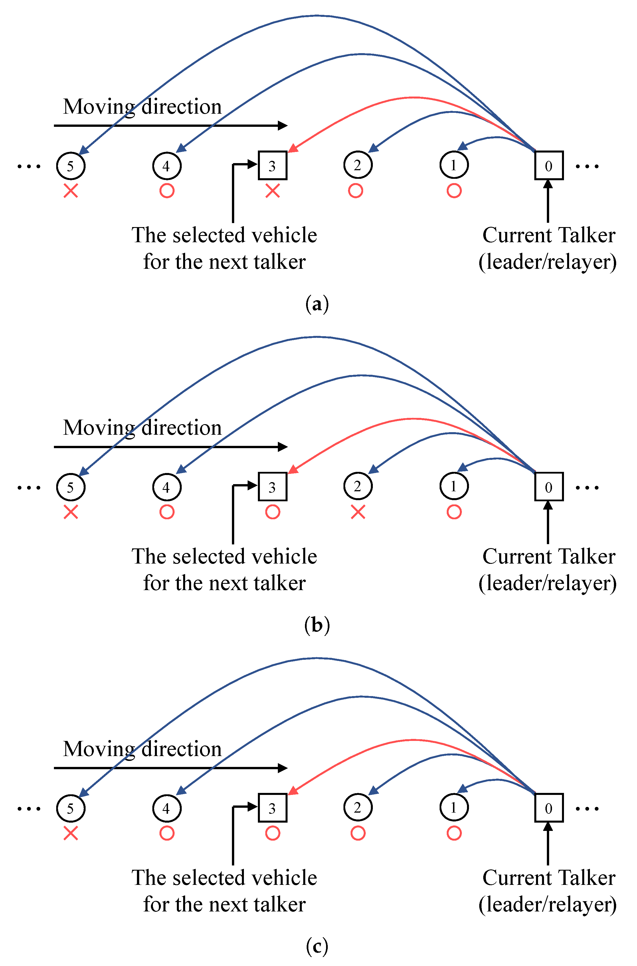
To achieve a multi-objective strategy while ensuring packet forwarding, the following ARQ-based relay protocol is designed in EMDS. In a slot, a talker transmit a control packet with selected power indicating next talker for the relay. Then, the packet reception states are divided into the three cases below. If a selected vehicle as the next talker does not successfully receive the packet and does not send ACK for the packet accordingly (case 1), the current talker re-transmits the packet with a new strategy (i.e., selection of a new transmit power and a new vehicle for the next talker) in the next slot. Although the selected vehicle as the next talker successfully received the packet, if the packet reception of the vehicles located between the current talker and the next talker fails (case 2), the current talker re-transmits the packet with a new strategy in the next slot to ensure packet forwarding, and the next talker considers the relay selection to be canceled and keeps silence by monitoring cumulative NDP-based ACKs feedback status to avoid the collision. Finally, If all vehicles between the current talker and the next talker, including the next talker, successfully receive the packet (case 3), the next talker is successfully designated and the next talker is responsible for the next transmission. Then, the next talker sends the packet in the next slot with a new strategy determined by itself to send the packet to further vehicles.
The operational examples of the ARQ-based relay protocol in EMDS are presented in Figure 3. There are six vehicles which is a part of the vehicle array forming the platoon and vehicle 0 driving in front is a talker broadcasting a packet in a given slot. In this examples, a talker indicates vehicle 3 as a next talker for the next slot. Figure 3a is an example of case 1 mentioned above. After broadcasting a packet from vehicle 0, if vehicle 3 does not successfully decode the packet, vehicle 0 cannot hear ACK from vehicle 3. In this case, although vehicle 1 and 2 are successfully receive the packet, the designation of a next talker fails; thus, vehicle 0 re-transmits the packet again in the next slot. Figure 3b is an example of case 2. After broadcasting a packet, vehicle 3 successfully receives the packet. However, vehicle 2 which is located between vehicle 0 and 3 fails to decode the packet; thus, vehicle 0 re-transmits the packet again in the next slot. Meanwhile, vehicle 3 keep silence in the next slot regarding the relay selection is failed. An example of case 3 is shown in Figure 3c. All vehicles from vehicle 1 to vehicle 3 have successfully received the packet; thus, the designation of the next talker is successful. Meanwhile, vehicle 4 also successfully received the packet which is located farther than vehicle 3 from the current talker, but the next talker is performed by vehicle 3 because the next talker is designated as vehicle 3 inside the packet. Meanwhile, vehicle 3 establishes a new strategy to forward packets in the next slot, taking into account that vehicle 4 has already successfully received the packet.

3.2. Adaptive Platoon Velocity Control Scheme

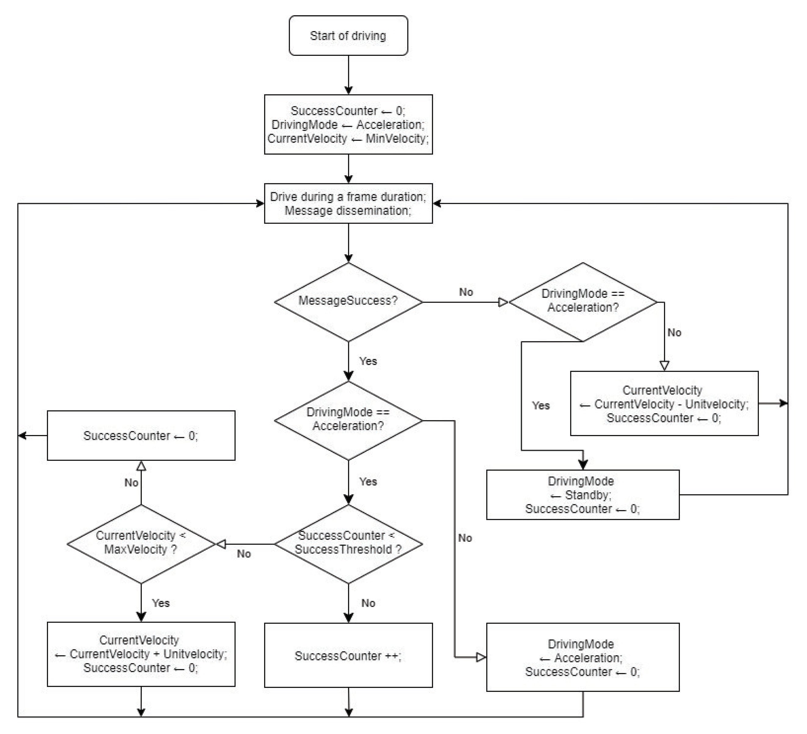
In this work, we introduce adaptive platoon velocity control scheme in EMDS based on the success rate of message dissemination. The scheme is based on ARF which is widely used as a rate adaptation scheme in commercial WLAN products. The ARF scheme is a heuristic rate adaptation scheme to select the data transmission rate by keeping track of previous transmission states. In this context, the platoon velocity control scheme in EMDS keeps track of successful dissemination of the previous messages and decides next platoon velocity in the next section of duration T s by using the block diagram shown in Figure 4. The concept of this scheme is based on the reliability of the vehicular network. If the platoon speed increases, the inter-vehicle distance increases and the probability of packet error increases. Therefore, if successful message dissemination is continued over a given level, the platoon velocity is increased to enhance the traffic throughput, but the velocity is decreased when the outage occurs to reduce the probability of packet error.
In Figure 4, UnitVelocity is the unit for increasing or decreasing the platoon speed where MinVelocity and MaxVelocity are minimum and maximum speed of the platoon, respectively. MessageSuccess means that every non-leader vehicle successfully received a control packet before the end of a section and the leader receives ACKs from all the other vehicles in the platoon accordingly. If a message is successfully disseminated in this way, then the leader sets driving mode to acceleration and increases SuccessCounter. However, in the acceleration driving mode, even if a message transmission is successful, the platoon does not increase the speed immediately. Only when multiple messages are successfully transmitted in succession by a given SuccessThreshold, the platoon increases the current velocity by one step. For this end, SuccessThreshold is shared by all the vehicle in the platoon from the start of the driving and the leader transmits current value of SuccessCounter in a control packet to enable non-leader vehicles compare SuccessCounter and SuccessThreshold in every section time. After change of the platoon velocity, SuccessCounter is reset to zero.
Meanwhile, if an outage occurs, vehicles resets SuccessCounter to zero and enter the standby mode for message dissemination errors by monitoring cumulative ACKs status. At first, the platoon maintains the current speed until the next section waiting for the result in the next section. At the end of the next section, if an outage occurs again, then the platoon speed is reduced or returns to the acceleration mode.

4. Mdp Formulation

Our goal is to sequentially decide on the optimal packet transmit power level and the optimal selection of the next talker with the consideration of energy efficiency of the message dissemination. In EMDS, the optimal decision making is conducted in every slot as explained in Section 3 based on the network conditions; deadline of the message dissemination, the number of vehicles in the platoon, and the platoon velocity. To this end, we formulate an MDP model with four elements: (1) state space; (2) action space; (3) state transition function; and (4) reward and cost functions [23]. Subsequently, we introduce the optimality equation and a value iteration algorithm to solve the equation.

4.1. State Space

We define the state space of a finite set S as
S = Δ V × G × C × M × U × T ,
which consists of the following components:
  • V = Δ v 1 , v 2 , · · · , v k , · · · , v K , 1 k K , denotes the state of the platoon velocity, where v K is the maximum platoon velocity. All the velocities are normalized with respect to a unit platoon velocity, v u . Thus, the velocity of the platoon is considered to be an integer multiple of v u and v k can be defined as k × v u .
  • G = Δ 0 , 1 is the set of driving modes of the platoon. The platoon takes the value 1 when it tries to accelerate the platoon velocity. On the contrary, the platoon takes the value 0 when it enters to the standby mode.
  • C = Δ 0 , 1 , 2 , · · · , C 1 is the state of the counter of the successful message dissemination, where C is a given threshold for the counter regarding consecutive successful message dissemination.
  • M = Δ 0 , 1 , 2 , · · · , M is the set of time-slots in the duration of a frame for the operation of platoon-based driving. That is to say, M is the union of two sets M S = Δ 0 , 1 , 2 , · · · , M 1 and M O = Δ M , where M S is the set of slots in the duration of a section and M O is the driving operation time, in which the platoon changes its velocity after the finish of the message dissemination. There are totally M slots in a section; thus, the number of possible packet transmission attempt is M. In conclusion, a message dissemination is conducted in first M slot times of M . After that, the change of the platoon velocity is performed in the ( M + 1 ) th slot in M .
  • U = Δ u 1 , u 2 , u 3 , · · · , u P is the set of packet reception states, where P is the total number of possible combinations of cumulative status of ACK reception from every non-leader vehicles, i.e., P = 2 N 1 , if there are totally N 1 vehicles in the platoon except the leader. Also, a possible case for the cumulative ACK reception is represented by a vector, u X , 1 X P , which is represented by u X = u 1 , u 2 , u 3 , · · · , u N 1 where u ζ ( 1 , N 1 ) is an index variable. That is, if ACK has been received from the the ζ th follower vehicle within current slot, u ζ = 1 . Otherwise, u ζ = 0 . For example, if the total number of non-leader vehicle is 5 and the first and third follower vehicles have sent their ACKs until the current slot, u X = 1 , 0 , 1 , 0 , 0 . In addition, u X u X , if X X .
  • T = Δ 1 , 2 , 3 , · · · , N 1 is the set of possible talkers, where total number of the vehicles in the platoon is N. Since talkers are vehicles who forward the control packets, tail is not included in the set of talkers.

4.2. Action Space

Based on the current state information, a talker of EMDS chooses a multi-objective action which consists of deciding the transmit power level and the next talker. Therefore, we define the action space of a finite set A as
A = Δ P × H ,
where P is the set of possible transmit power level and H is the set of the number of hops to the next talker that the current talker wants to indicate. P can be represented as
P = Δ 0 , 1 , 2 , , P max ,
where P max is the maximum power level for the packet transmission. We normalize all transmit powers with respect to a minimum possible transmit power in mW, P m W , which is typically injected by the lower end of the linearity range of RF amplifier on wireless network interfaces. Thus, the transmit power is considered to be an integer multiple of P and the nth power level can be defined as n × P . Meanwhile, zero transmit power level, 0 P , means that a talker chooses not to send a packet. For example, if a message dissemination is completed before deadline, the talker does not need to send the control packet in the remaining slots. In this case, the talker selects zero transmit power level. Meanwhile, H can be defined as
H = Δ 0 , 1 , 2 , , N 2 ,
where the total number of vehicles in the platoon is N. This means that the current talker includes the number of hops to the next talker, i H , 0 i N 2 , in a control packet to specify the next talker. For example, given that the current talker is third vehicle from the leader and it want to indicate sixth vehicle as a next talker. Then, the current talker sets three-hop be in a control packet. Meanwhile, if the current talker sets zero-hop, 0 H , it is to designate itself as the next talker.

4.3. State Transition Function

Let k , g , c , m , x , and t are the indices for components of the state V , G , C , M , U , and T , respectively, while b and h are the indices for action components P and H . In addition, we assume that two arbitrary states in S be s = Δ k , g , c , m , x , t and s = Δ k , g , c , m , x , t , and an arbitrary action in A be a = Δ b , h . The state transition function is the probability that system starts from state s and ends in state s by taking an action a. Since the message dissemination time and the driving operation time occur sequentially in the order of slots, every component is dependent on M . During the driving operation times, V is dependent on G , C , and U , while G and C are dependent on U . Meanwhile, during the message dissemination times, U and T are dependent on V as well as A . Therefore, the state transition function can be described by
Pr s | s , a = Pr m | m × Pr k | k , g , c , m , x × Pr g , c | g , c , m , x × Pr x , t | x , t , a , k , m .
The transition probability for time-slots, Pr m | m , can be expressed as
Pr m | m = Δ δ m , m + + ,
where m + + = Δ m + 1 mod M + 1 and δ m , m + + is the Kronecker delta function. Here, the term δ m , m + + means that times-slot index always increases one at a time until the end of the frame.
When m = M and x = P , when it is the driving operation time after successful message dissemination during the section time, the platoon increases its velocity until the velocity reaches to the maximum speed only if g = 1 and c = C 1 . Therefore, the transition probability of V can be derived as
Pr k | k , g = 1 , c C 1 , m = M , x = P = 1 , if k = k 0 , otherwise ,
and
Pr k | k , g = 1 , c = C 1 , m = M , x = P = 1 , if k = k + 1 , k K 1 , if k = k , k = K 0 , otherwise .
On the other hand, when g = 0 , m = M , and x P , the platoon decreases its velocity until the velocity reaches to the minimum speed. Unlike the acceleration driving mode, there is no threshold for c, so if the message dissemination failure occurs, it is immediately reflected as the platoon velocity deceleration. Then, the transition probability of V is given by
Pr k | k , g = 0 , c , m = M , x P = 1 , if k = k 1 , k 1 1 , if k = k , k = 1 0 , otherwise .
In the case of x = P , the platoon returns to the acceleration mode maintaining its velocity. Thus, we have the transition probability of V as
Pr k | k , g = 0 , c , m = M , x = P = 1 , if k = k 0 , otherwise .
Meanwhile, the platoon can change its speed only after the deadline time of the message dissemination and maintains its velocity during a section time. Thus, if m M , the transition probability of V can be represented as
Pr k | k , g , c , m M , x = 1 , if k = k 0 , otherwise .
With the start of the driving operation time, the platoon checks the success of the message dissemination and adjusts its driving mode, g, and the successful message dissemination counter, c. In the case of successful message dissemination, the platoon set its driving mode as acceleration and increase counter one at a time. In addition, the platoon resets c to zero if the message dissemination succeeds while c is C 1 , the platoon resets c as zero. Therefore, the transition probability of G and C can be derived as
Pr g , c | g = 1 , c C 1 , m = M , x = P = 1 , if g = 1 , c = c + 1 0 , otherwise ,
and
Pr g , c | g = 1 , c = C 1 , m = M , x = P = 1 , if g = 1 , c = 0 0 , otherwise .
Meanwhile, in the standby mode, the platoon changes its driving mode as acceleration and resets the counter after successful message dissemination and thus, the transition probability of G and C can be given by
Pr g , c | g = 0 , c = 0 , m = M , x = P = 1 , if g = 1 , c = 0 0 , otherwise .
If the message dissemination fails, the driving mode keeps its mode as standby and the counter is reset to zero and the transition probability can be expressed as
Pr g , c | g = 0 , c = 0 , m = M , x P = 1 , if g = 0 , c = 0 0 , otherwise .
Lastly, the driving mode and the counter maintain their value during the section time. Therefore, we have the transition probability as
Pr g , c | g , c , m M , x = 1 , if g = g , c = c 0 , otherwise .
During the driving operation time ( m = M ), irrespective of the current status of U and T , they are initialized for the dissemination of the next message. Therefore, the joint transmission probability of U and T can be given by
Pr x , t | x , t , a , k , m = M = 1 , if x = 1 , t = 1 0 , otherwise .
In each slot in the message dissemination time ( m M ), the next packet reception state and the next talker are determined according to the ARQ-based relay protocol along with an action selected by the current talker. Accordingly, the joint transition probability of U and T is Pr x , t | x , t , a = b , h , k , m . Meanwhile, t is dependent on x as described in Section 3.1; thus, by the Bayes rule, the joint transition probability can be represented as
Pr x , t | z = Pr x t z Pr z = Pr t | x z × Pr x z Pr z = Pr t | x , z × Pr x | z ,
where we assume Pr z = Δ Pr x , t , a = b , h , k , m M for the convenience. Therefore, when m M , the joint transition probability can be derived as
Pr x , t | z = δ ( t , t + h ) × Φ t t + h u x + δ ( t , t ) × 1 Φ t t + h u x × ς = t N μ v k u ς , u ς , b , if h ( 0 , N t 1 ) 0 , otherwise ,
where Φ t t + h u x is the product of values of the elements from the tth to the ( t + h ) th in vector u x , and μ v k u ς , u ς , b is the transition probability of U according to the transmit power b while the platoon velocity is v k . In other words,
Φ t t + h u x = Δ ς = t t + h u ς , u ς u x ,
and
μ v k u ς , u ς , b = Δ δ ( u ς , 0 ) P E v k ς , b , t 1 u ς × 1 P E v k ς , b , t u ς + δ ( u ς , 1 ) × δ ( u ς , 1 ) ,
where u ς u x , u ς u x .
Here, P E v k ς , b , t is the probability that a control packet transmitted at power P b = b × P m W from talker t will be received in error at the ς th follower vehicle when the platoon velocity is v k . This probability depends on the modulation and coding scheme, and if we consider quadrature phase-shift keying (QPSK) transmission under additive white Gaussian noise (AWGN) channel, the packet error probability can be expressed as
P E v k ς , b , t = 1 1 1 2 1 erf P b 10 φ t , ς d B / 10 N 0 l ,
where erf · is Gauss error function, l is the packet size in bits, φ t , ς d B is the path loss between vehicle t and ς described in (2), and N 0 is the noise power spectral density.

4.4. Reward and Cost Functions

To define the reward and cost functions, we consider expected value of the successful packet reception and the energy consumed to transmit the packet. First, we define the total reward function, r ( s , a ) as
r s , a = α f s , a 1 α g s , a ,
where f ( s , a ) and g ( s , a ) are the reward function for the sum of the probabilities of successful packet receptions at follower vehicles in each transmission and the cost function for the energy consumption for the transmission at the talker, respectively. α is a weighted factor to determine the importance of the reward and cost functions.
Given that a talker t transmits a control packet with power P b , then the sum of the probabilities of the newly added successful packet receptions at the slot can be obtained for f ( s , a ) as
f s , a = Δ ς = t N δ u ς , 0 1 P E v k ς , b , t , u ς u x , if m M 0 , otherwise ,
while the cost function can be defined as g s , a = Δ P b m W . To adjust values of the two functions become common scale, we perform normalization by using Min-Max scaling.

4.5. Optimal Equation

A power control and a relay selection policy π describes a decision rule that determines the action taken by the talker. The expected total reward obtained over an infinite time horizon, which is expressed as
V π s 0 = lim y 1 y E π n = 1 y r S n , a n | S 0 = s 0 ,
where n 1 , 2 , is the slot index, S n is the state sequence, a n is the action sequence, s 0 is the initial state, and E π denotes the expectation with the policy π .
The goal here is to find a policy that maximizes the expected total reward. For this end, we first find the maximum expected total reward that can be described as
V s 0 = max π Π V π s 0 ,
where Π is the set of all stationary deterministic policies. Please note that the expected total reward can be maximized when the talker takes the most beneficial action a in each state s. Therefore, the optimal equation known as the Bellman optimality equation [24] is given by
V s 0 = max a A r s 0 , a + s S λ Pr s | s 0 , a V s ,
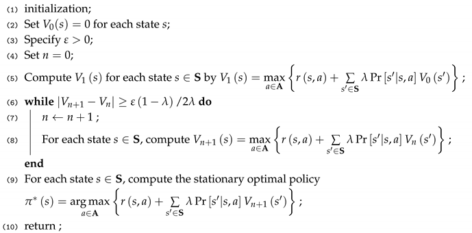
where λ is a discount factor in the MDP model. λ closer to 1 gives greater weight to future rewards. Then, the optimal action a is the action that satisfies the optimal equation. To solve the optimality equation and to obtain the optimal policy π , we use a value iteration algorithm, as shown in Algorithm 1, where V = max V s for s S .
Algorithm 1: Value iteration algorithm.
Energies 13 03940 i001
In general, each iteration in the value iteration algorithm is performed in a polynomial time as O A S 2 [25]. Since this complexity cannot be neglected, each vehicle of the platoon uses a table to store the optimal policy regarding the transmit power and relay selection according to the platoon velocity. Then, each of them performs the decision making referring the table when it is designated as a talker. This table includes the state and the decision for each state and can be computed in advance to the beginning of driving by the value iteration. Thus, when the vehicles forming their platoon, the leader creates the table and shares it with its follower vehicles. In this way, EMDS can be applied to the vehicle without high computational overhead.

5. Performance Measures

In this section, we derive the outage probability, the average velocity, and the expected energy consumption as performance measures of EMDS. To this end, we can obtain an optimal action vector that matches an optimal action to each state by solving the MDP model in Section 4. Given that a velocity of the platoon is v, a frame time for a message consists of slots 0 , 1 , 2 , , M . The packet reception state is u 1 = 0 , 0 , , 0 at the start of frame. That is to say, packet reception status for each follower vehicle is initialized to zero. The talker also be initialized as a leader, t = 1 . At the end of each slot, state u x and t transits to next state by selecting an optimal action according to the optimal policy. At the end of the frame time (i.e., slot M), irrespective of the final packet reception state and talker, it always transits to initial state of U and T for the next message under updated velocity v . Therefore, when an optimal policy is established, the states are placed on the repeated transition cycle under the condition of the current velocity v and the outage probability can be written as
P o u t = Δ v P v × 1 P s u c v ,
where P v is the stationary probability that the platoon velocity is v during the frame time and P s u c v is the successful message dissemination probability under the condition of the platoon velocity v.
Now, P s u c v is the sum of probabilities of the states that have u x = u P at slot m = M , which is given by
P s u c v = Δ t P M v x = P , t ,
where P M v x , t is given by the recursive relation over slots, M, as
P M v x , t = Δ x t Pr x , t , M | x , t , a x , t , v , M 1 , M 1 , v × P M 1 v x , t ,
and a x , t , v , M can be found in the optimal action vector with the state parameters.
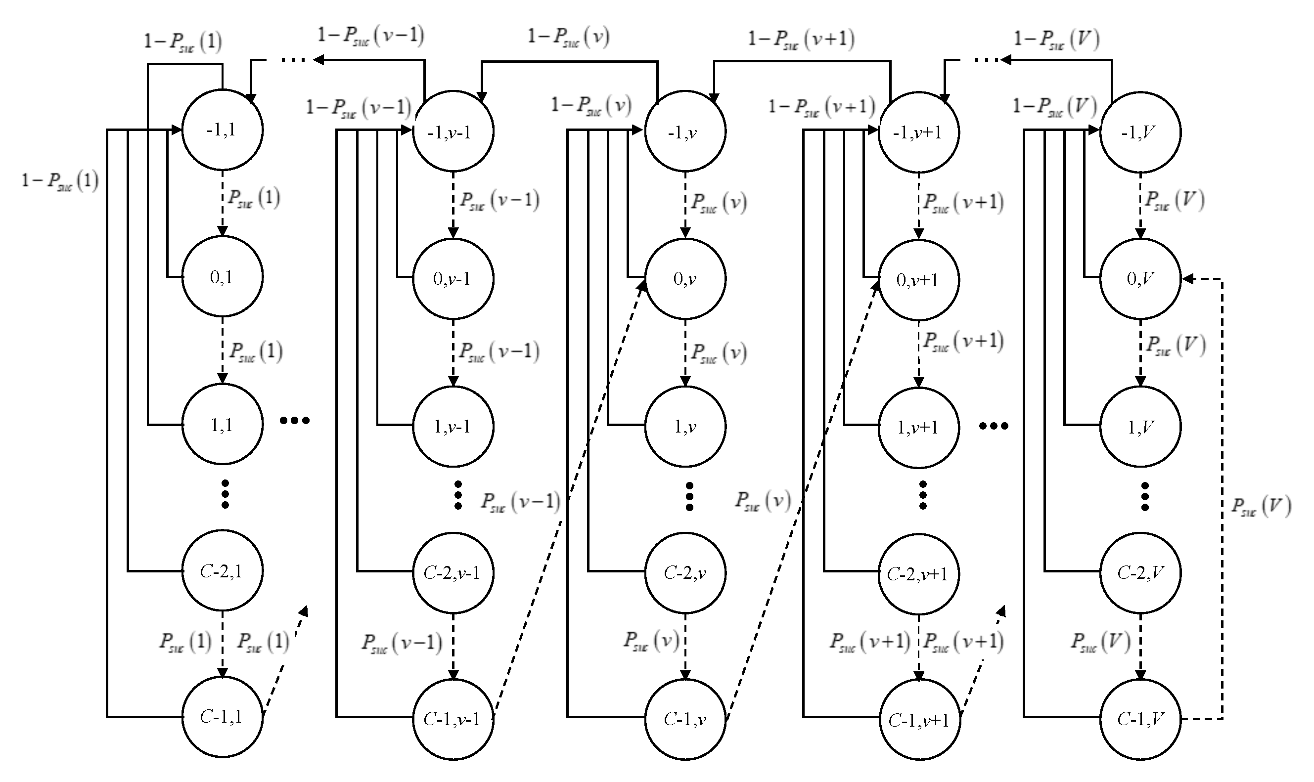
After that, with the successful message dissemination probability of velocity v, P s u c v , The evolution of the system is defined as a Discrete Time Markov Chain (DTMC) to obtain the stationary probability P v , as shown in Figure 5. Let b = c t , v t be the stochastic process representing the successful dissemination counter and the platoon velocity at the start of frame time for the tth message. Then, the stochastic process of the counter can be defined as
c t = Δ 1 , Message dissemination failed , standby driving mode , 0 , Reset , i , Success of i consecutive messages dissemination , i { 1 , · · · , C 1 } ,
and the stochastic process v t represents the platoon velocity ( 1 , 2 , · · · , V ) .
One step-transition probabilities for the stochastic process b t c , v are
Pr c + 1 , v | c , v = P s u c v , v 1 , V , c 0 , C 2 , Pr 1 , v | c , v = 1 P s u c v , v 1 , V , c 0 , C 1 , Pr 0 , v + 1 | C 1 , v = P s u c v , v 1 , V 1 , Pr 1 , v 1 | 1 , v = 1 P s u c v , v 2 , V , Pr 0 , V | C 1 , V = P s u c V . Pr 1 , 1 | 1 , 1 = 1 P s u c 1 ,
The first equation in Equation (34) accounts for the fact that successful message dissemination counter increases by one until it reaches maximum threshold value if there is consecutive success without failure. The second equation accounts for the fact that if there is message dissemination failure, c t becomes 1 , since EMDS changes driving mode as standby. The third equation means that if there is a consecutive successful message dissemination as many as the counter threshold in acceleration driving mode, then counter is reset as zero and the platoon velocity is increased by one. Meanwhile, in the standby driving mode, if a message dissemination failure occurs, then the counter is reset as zero and the platoon velocity is decreased by one as shown in the fourth equation. The fifth and sixth equations represent the special situations when the velocity is the maximum or the minimum regarding the third and fourth equations, respectively.
Let b c , v = lim t Pr c t = c , v t = v , c 1 , C 1 , v 1 , V be the stationary distribution of the chain. To obtain a closed-form solution, we first aggregate the states corresponding to b c , v for different counter values c into a single state of v, which is Ψ v = P v , v ( 1 , V ) . Then the Markov chain model can be transformed into a birth-death chain. Since, the equilibrium distribution of a V state birth-death chain with birth rates λ v , v ( 1 , V 1 ) , and death rates μ v , v ( 2 , V ) , is given by
Ψ v = 1 1 + j = 1 V 1 i = 1 j λ i μ i + 1 , if v = 1 , λ v 1 μ v Ψ v 1 , if v 2 , V ,
After that, λ v and μ v can be written as [26]
λ v = b C 1 , v Pr 0 , v + 1 | C 1 , v Ψ v = b C 1 , v P s u c v Ψ v , v ( 1 , V 1 ) ,
μ v = b 1 , v Pr 1 , v 1 | 1 , v Ψ v = b 1 , v 1 P s u c v Ψ v , v ( 2 , V ) .
Hereafter, we abbreviate P suc ( v ) as p v .
From the Markov chain model, the balance equations can be obtained as
b c , v = p v c b 0 , v , c 1 , C 1 , v 1 , V ,
b 1 , v = 1 p v c = 0 C 1 b c , v + 1 p v + 1 b 1 , v + 1 , v 2 , V 1 ,
b 1 , 1 = 1 p 1 c = 0 C 1 b c , 1 + 1 p 2 b 1 , 2 ,
b 0 , v = p v 1 b C 1 , v 1 + p v b 1 , v , v 2 , V .
Then, using (35)–(37), Equation (41) can be converted as
b 0 , v = p v 1 b C 1 , v 1 + p v b 1 , v = Ψ v 1 λ v 1 + p v b 1 , v = Ψ v μ v + p v b 1 , v = 1 p v b 1 , v + p v b 1 , v = b 1 , v , v 2 , V .
In first, μ v can be obtained using Ψ v , which is
Ψ v = c = 0 C 1 b c , v + b 1 , v .
Then, using (38) and (42), Ψ v can be written by
Ψ v = c = 0 C 1 b c , v + b 1 , v = 1 p v C 1 p v b 0 , v + b 1 , v = 2 p v p v C 1 p v b 1 , v , v 2 , V .
After that, μ v can be given by
μ v = b 1 , v 1 p v Ψ v = 1 p v 2 2 p v p v C , v 2 , V .
Next, λ v is considered. Ψ v can be expressed as
Ψ v = c = 0 C 1 b c , v + b 1 , v = p v C 1 p v 1 1 b C 1 , v + b 0 , v = 2 p v C p v C 1 1 p v 1 1 b C 1 , v , v 2 , V 1 .
After that, λ v for v ( 2 , V 1 ) can be obtained as
λ v = b C 1 , v p v Ψ v = 1 p v 2 p v C p v C 1 1 , v 2 , V 1 .
Meanwhile, to earn λ v for v = 1 , (40) can be converted by using (35) as
b 1 , 1 = 1 p 1 c = 0 C 1 b c , 1 + μ 2 Ψ 2 = 1 p 1 c = 0 C 1 b c , 1 + λ 1 Ψ 1 = 1 p 1 c = 0 C 1 b c , 1 + p 1 b C 1 , 1 .
Here, the stationary probability of state v = 1 is
Ψ 1 = c = 0 C 1 b c , 1 + b 1 , 1 = 2 p 1 c = 0 C 1 b c , 1 + p 1 b C 1 , 1 = 2 p 1 C p 1 C + 1 1 p 1 1 1 b C 1 , 1 .
Through this, λ 1 can be expressed as
λ 1 = b C 1 , 1 p 1 Ψ 1 = 1 p 1 2 p 1 C p 1 C + 1 1 .
Applying λ v for v ( 1 , V 1 ) and μ v for v ( 2 , V ) to (35), we can have the stationary probability of the platoon velocity P ( v ) Ψ v . Finally, using this, the outage probability, P out , can be obtained by (30). The average platoon velocity also can be obtained as v a v g = Δ i = 1 V v i P i . In addition, applying recursive relations of (32), the expected energy consumption at a given velocity can be given by
E a v g v = Δ m = 0 M 1 x t P m v x , t × P m W a x , t , v , m ,
where P m W a is the transmit power according to the action a . Therefore, the expected energy consumption of EMDS can be expressed as
E a v g = Δ i = 1 V E a v g i P i .

6. Evaluation Results

For the performance evaluation, we conducted extensive simulations with MATLAB R2020a version and compare the proposed scheme, EMDS, with four schemes: (1) MP where the fixed power is allowed to transmit a control packet at every talker, while flexible relay selection is possible. To compare with EMDS, the fixed power of MP is set to the maximum transmit power of EMDS; (2) 2H where only vehicles located at a fixed distance of 2-hop from the current talker can be determined as the next talker, while multiple transmit power can be selected; (3) 1H where only one-hop-based relay is allowed, while multiple transmit power can be selected; (4) DV where only a dedicated vehicle is allowed to relay messages during dissemination. In this simulation, a vehicle located in the middle of the platoon is selected as a dedicated relay vehicle for DV.
In terms of simulation settings, we consider time headway and standstill gap including vehicle length as 1.6 s and 5 m, respectively. In EMDS, it takes into account the operating bandwidth of 5.9 GHz commonly used in IEEE 802.11p [27] and IEEE 802.11bd [28], the latest Wi-Fi V2X revisions currently in development for vehicle networks; thus, log-distance path loss model of EMDS holds the bandwidth parameters of 5.9 GHz. The length of the control packet l is 64 bytes. The maximum transmit power is assumed as 45 mW and four levels of transmit power control is possible in every scheme except MP. The initial platoon velocity is 8 m/s and unit velocity is 5 m/s. In the following evaluations, three-levels of the platoon velocities are considered. This means that the inter-vehicle distance will be between 18 m and 34 m, depending on the speed and almost 45% and 100% of packet errors occur with the maximum transmit power between two-hop and three-hop distanced vehicles with the maximum velocity. The counter C of the set C is set to three. For the value iteration, we set the value of the discounter factor λ as 0.90. Please note that all simulation parameters have been carefully reviewed through precise calibration and thus we believe similar tendency will be obtained in practical vehicular environments. However, dynamics (e.g., driving velocity of vehicles in a platoon) in vehicular environments cannot be fully considered in the simulations. Therefore, it is necessary to additionally consider realistic traffic dynamics as a future work.

6.1. Outage Probability

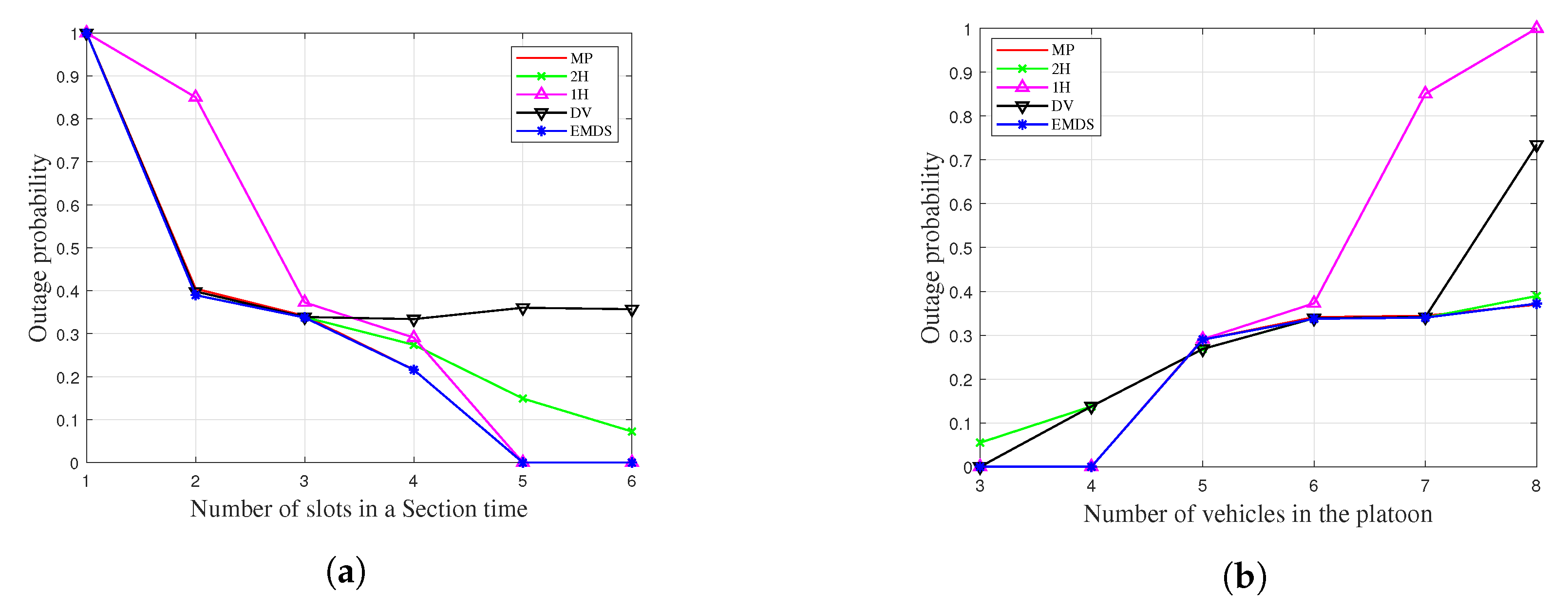
Figure 6 compares the outage probability of the comparison schemes with EMDS. In Figure 6a, the outage probabilities are evaluated against the number of possible packet transmission attempt, M, in a section time. When M = 1 , the outage probabilities of all schemes are 1, and the message dissemination failures are definite. Because there is only one possible attempt for the packet transmission, there is no opportunity to relay messages. In other words, since the total number of vehicles is six, even if the transmission is performed at the maximum power, it is out of the transmission range from the reader. After M = 2 , the outage probabilities drop sharply, while the outage probability of 1H is still high in M = 2 . This shows the relative importance of specifying the next talker. In the case of 1H, only one-hop-distance-based relay is possible; thus, in the second transmission attempt, the distance between the talker and the tail is too far, resulting in a high probability of message dissemination failure.
In the case of the 4-slots, EMDS outperforms the other schemes (except MP) by 22∼36% of the outage probability. Since MP is a scheme that always transmits at the maximum power, it has the lowest outage probability. The figure shows that EMDS scheme has a comparable outage probability, regardless of the number of slots, when compared to MP. In particular, EMDS achieves zero outages when M = 5 , which is different from the other relay schemes such as 2H and DV, demonstrating the benefits of the dynamic indicating of a next talker. In the case of MV, only the vehicle located in the middle can forward the message, so the packets are repeatedly transmitted in the designated relay vehicle. If the distance to the tail is far away, there is a high probability of failure. As a result, it shows that the high outage probability is maintained after M = 3 .
Figure 6b shows the comparison of the outage probabilities against the number of vehicles in the platoon, N. While only a fixed number of transmissions, M = 3 , is possible, the outage probabilities of all schemes generally increase as the number of vehicles increases. After seven vehicles of the figure, the probability of outage of 1H and DV rises sharply. This is because, considering the short transmission period of 3-slots, the distance from the last talker to the tail is far, so it can be seen that packet transmission failure occurs in the last talker. In the case of EMDS, it can be confirmed that an optimal decision is made in selecting a relay vehicle in consideration of both the number of possible transmissions and the total number of vehicles, and as a result, it shows that EMDS has almost the same outage probability as MP. In N = 8 , EMDS outperforms the other schemes by 12%∼50% in terms of outage probability. In conclusion, it can be seen that as the number of vehicles increases, the performance of the outage probability of EMDS is relatively increased compared to the other schemes.

6.2. Average Velocity Level

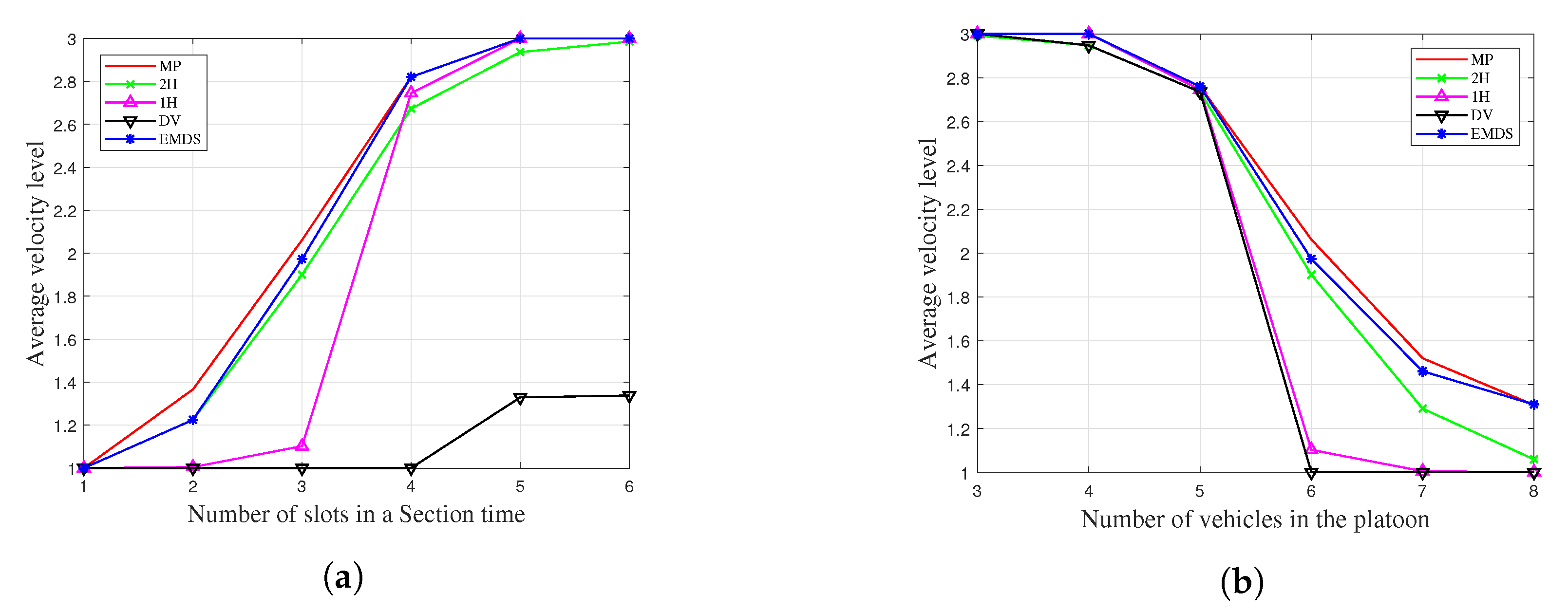
Figure 7 compares the average velocity level of the comparison schemes with EMDS. As mentioned earlier, we set three possible velocities for all schemes. The average velocity shows the performance of traffic throughput for each scheme. In particular, this performance has a close correlation with outage probability. Basically, the distance between vehicles is proportional to the velocity of the platoon, and it means that the probability of packet transmission failure increases as the velocity increases. Meanwhile, if the velocity decreases, the distance between vehicles decreases, and the probability of packet transmission failure decreases. According to the adaptive platoon velocity control algorithm, if the outage probability decreases, the velocity increases, and the increased velocity increases the outage probability again, resulting in negative feedback. In Figure 7a, the average velocity levels are evaluated against the number of possible packet transmission attempt in a section time. This figure shows that EMDS has comparable performance to MP when only a low number of transmissions is possible, and shows that it has almost the same performance when sufficient number of transmissions is possible. As can be seen in Figure 6a, EMDS achieves the zero outage with 5 slots, so EMDS achieves the maximum velocity from 5 slots in the the average velocity of Figure 7a. At M = 3 , EMDS outperforms 2H and 1H by 10 % and 87 % in terms of the average velocity, respectively.
In Figure 7b, the average velocity levels are evaluated against the number of vehicles in the platoon. While only a fixed number of transmissions, M = 3 , is possible, the average velocity level of all schemes generally decrease as the number of vehicles increases influenced by an increase in outage probability. However, as the total number of vehicles increases, the average velocity level of the EMDS is rising relative to the comparative schemes. When there are eight vehicles in a platoon, the EMDS achieves almost the same speed as the MP and shows a performance improvement of almost 30 percent over 2H about the average velocity. This demonstrates the scalability of EMDS over the total number of vehicles. This is because the burden of increasing the number of vehicles can be minimized in EMDS through optimized decision making of power control and relay selection. Meanwhile, in the case of 1H and DV, if there are more than 6 vehicles, their speeds remains near the minimum level, which is an example of the lack of scalability when a limited transmission power (e.g., M = 3 ) and a limited number of transmissions are given (e.g., the maximum transmit power of 45 mW).

6.3. Energy Efficiency

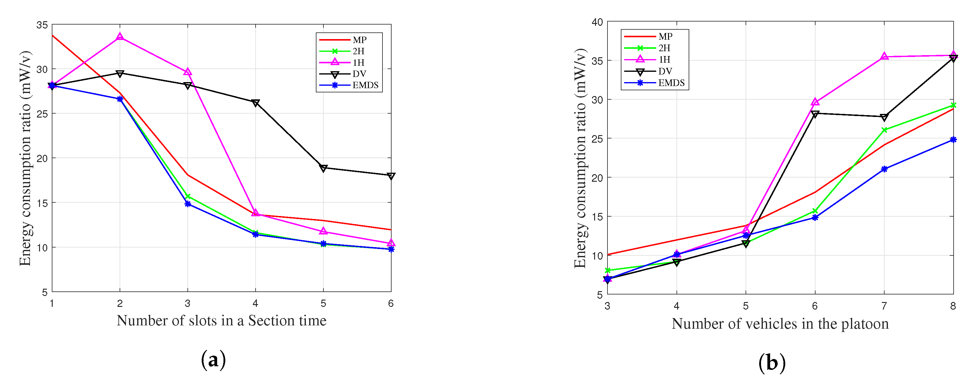
Figure 8 compares the energy consumption rates (mW/v) of the comparison schemes with EMDS, which are the results of dividing the expected energy consumption values (mW) by the average velocity levels ( v ) . Therefore, the lower the energy consumption rate, the better the energy efficiency of a scheme. In Figure 8a, the energy consumption rates are evaluated against the number of possible packet transmission attempts in a section time. EMDS shows 31% and 23% better energy efficiency on average than the other schemes when M is 3 and 4, where it is relatively harsh conditions for the message dissemination with small transmission opportunities. It can be seen that the energy efficiency of the other comparison schemes improves as the number of transmissions increases. However, considering the previous performance evaluation results such as the outage probability and the average velocity of EMDS, are comparable to those of MP, the fact that the energy consumption rate of EMDS is 20% less on average in all regions than MP means that the energy efficiency of EMDS is enhanced with optimal decisions. This means that compared to the relaying protocols of the consulted literature assuming a fixed power such as [15], there is no performance degradation in terms of outage probability and average velocity despite EMDS transmitting with smaller power. Meanwhile, in the case of DV, despite maintaining a low speed due to a high outage probability, it can be seen that the transmissions of high power are continued to obtain a reward.
In Figure 8b, the energy consumption rates are evaluated evaluated against the number of vehicles in the platoon. The energy efficiency of EMDS improved by an average of 18% compared to MP over the entire range. Also, it shows that the energy efficiency of EMDS is more improved compared to the other schemes as the number of vehicles increases. In particular, as the total number of vehicles increases, the increase of energy efficiency improvement of EMDS compared to 2H shows that the energy efficiency of dynamic relay is higher than that of fixed length relay. That is, a lower amount of energy is consumed to maintain a similar outage probability or to maintain a higher velocity. Meanwhile, it can be seen that DV and 1H consume higher power to increase network reliability to address high outage probability even though they are in low velocity.

6.4. Effect of α

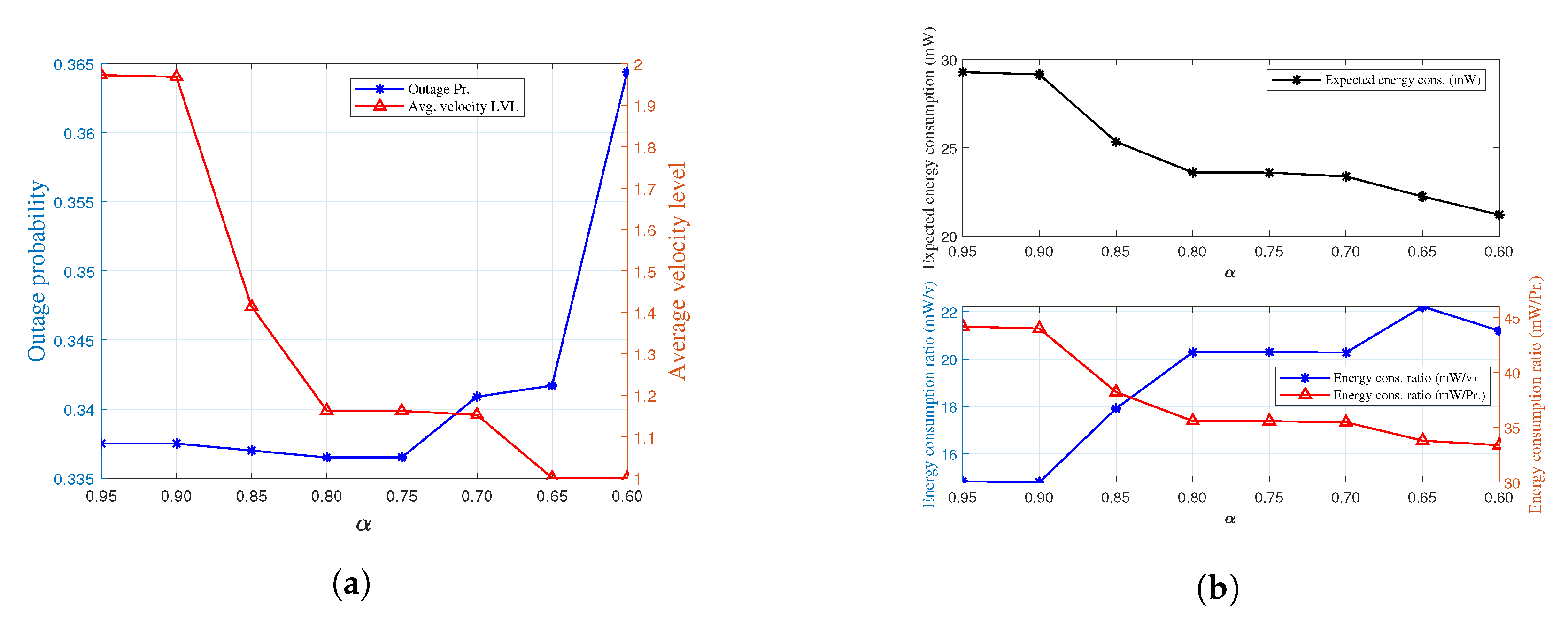
Figure 9 shows the effect of α over performance metrics of EMDS. α is a weighted factor applied to total reward function of MDP model to adjust the ratio between reward and the energy consumption. In Figure 9a, the outage probability and the average velocity level of EMDS are demonstrated, varying the value of α . As can be seen intuitively, as the α value decreases, the EMDS decreases the transmission power. Therefore, the average velocity level falls significantly, while the outage probability increases very slightly. This is because the reduced velocity limits the increase rate of outage probability even if the packet is transmitted with less power.
In the upper part of Figure 9b, the expected energy consumption of EMDS over α is demonstrated. We can confirm that the transmission power level of the EMDS is adjusted without any problems by changing the alpha value. In the bottom part of Figure 9b, the expected energy consumption per velocity level (mW/v) which is the result of dividing the expected energy consumption values (mW) by the average velocity level ( v ) and the expected energy consumption per the probability of successful message dissemination (mW/Pr.) which is the result of dividing the expected energy consumption values (mW) by the successful probability ( 1 P o u t ) are demonstrated. Therefore, in the both graph, the lower the energy consumption rate, the better the energy efficiency of EMDS. The two graphs in the figure show the opposite results: the energy efficiency over the velocity decreases as the α decreases, and the energy efficiency over the success probability increases as the α decreases. As you can see in Figure 9b, this means that the transmission power requirement for successful message dissemination was reduced due to the large reduction in velocity caused by the reduction in transmission power.

7. Conclusions

In this paper, we proposed an energy efficient message dissemination scheme (EMDS) in platoon-based driving systems to enhance the energy efficiency and traffic throughput while meeting transmission deadlines, using the proper power control and relay selection. To obtain the optimal policy that balances the probability of successful message dissemination and transmission power cost in EMDS, we formulated a Markov decision process (MDP) problem and derived the key performance measures. Extensive evaluation results demonstrate that EMDS can achieve the comparable performance in terms of the average velocity and the outage probability even with less energy consumption compared to the maximum power transmission scheme. This means that EMDS has better message dissemination efficiency in terms of energy efficiency than the conventional schemes with fixed transmission power. In addition, it can be found that EMDS outperforms the fixed relay scheme for all performance measures. In our future work, we will investigate how to disseminate messages more efficiently by means of state-of-the-art communications technologies under more dynamic vehicular conditions.

Author Contributions

Conceptualization, T.K. and S.P.; methodology, T.K. and T.S.; software, T.K.; validation, T.K., T.S. and S.P.; formal analysis, T.K., T.S. and S.P.; writing—original draft preparation, T.K., T.S. and S.P.; writing—review and editing, S.P.; visualization, T.K.; supervision, S.P.; project administration, T.K. and S.P.; funding acquisition, S.P. All authors have read and agreed to the published version of the manuscript.

Funding

This work was supported in part by the National Research Foundation of Korea (NRF) grant funded by the Ministry of Science and ICT (NRF-2019R1G1A1099718) and in part by ITRC (Information Technology Research Center) support program (IITP-2019-2017-0-01633).

Acknowledgments

We gratefully appreciate the anonymous reviewers’ variable reviews and comments.

Conflicts of Interest

The authors declare no conflict of interest.

References

  1. Peng, H.; Li, D.; Abboud, K.; Zhou, H.; Zhao, H.; Zhuang, W.; Shen, X.S. Performance Analysis of IEEE 802.11 p DCF for Multiplatooning Communications With Autonomous Vehicles. IEEE Trans. Veh. Technol. 2017, 66, 2485–2498. [Google Scholar] [CrossRef]
  2. Alam, A.; Gattami, A.; Johansson, K. An experimental study on the fuel reduction potential of heavy duty vehicle platooning. In Proceedings of the 13th International IEEE Conference on Intelligent Transportation Systems, Funchal, Portugal, 19–22 September 2010; pp. 306–311. [Google Scholar]
  3. Marzbani, H.; Khayyam, H.; Quoc, C.N.T.O.Đ.; Jazar, R.N. Autonomous Vehicles: Autodriver Algorithm and Vehicle Dynamics. IEEE Trans. Veh. Technol. 2019, 68, 3201–3211. [Google Scholar] [CrossRef]
  4. Wu, Q.; Nie, S.; Fan, P.; Liu, H.; Qiang, F.; Li, Z. A Swarming Approach to Optimize the One-Hop Delay in Smart Driving Inter-Platoon Communications. Sensors 2018, 18, 3307. [Google Scholar] [CrossRef] [PubMed] [Green Version]
  5. Wang, C.; Dai, Y.; Xia, J. A CAV Platoon Control Method for Isolated Intersections: Guaranteed Feasible Multi-Objective Approach with Priority. Energies 2020, 13, 625. [Google Scholar] [CrossRef] [Green Version]
  6. Dey, K.C.; Yan, L.; Wang, X.; Wang, Y.; Shen, H.; Chowdhury, M.; Soundararaj, V. A Review of Communication, Driver Characteristics, and Controls Aspects of Cooperative Adaptive Cruise Control (CACC). IEEE Trans. Intell. Transp. Syst. 2016, 17, 491–509. [Google Scholar] [CrossRef]
  7. Zhou, T.; Sharif, H.; Hempel, M.; Mahasukhon, P.; Wang, W.; Ma, T. A novel adaptive distributed cooperative relay MAC protocol for vehicular networks. IEEE J. Sel. Areas Commun. 2011, 29, 72–82. [Google Scholar] [CrossRef] [Green Version]
  8. Fasolo, E.; Zanella, A.; Zorzi, M. An effective broadcast scheme for alert message propagation in vehicular ad hoc networks. Proc. IEEE ICC 2006, 3960–3965. [Google Scholar]
  9. Tonguz, O.K.; Wisitpongphan, N.; Fan, B. DV-CAST: A distributed vehicular broad- cast protocol for vehicular ad hoc networks. IEEE Wirel. Commun. 2010, 17, 47–57. [Google Scholar] [CrossRef]
  10. Kaul, S.; Gruteser, M.; Rai, V.; Kenney, J. Minimizing age of information in vehicular networks. In Proceedings of the 2011 8th Annual IEEE Communications Society Conference on Sensor, Mesh and Ad Hoc Communications and Networks, Salt Lake City, UT, USA, 27–30 June 2011; pp. 350–358. [Google Scholar]
  11. Bharati, S.; Zhuang, W. CAH-MAC: Cooperative ADHOC MAC for vehicular networks. IEEE J. Sel. Areas Commun. 2013, 31, 470–479. [Google Scholar] [CrossRef] [Green Version]
  12. Yang, F.; Tang, Y. Cooperative clustering-based medium access control for broadcasting in vehicular ad-hoc networks. IET Commun. 2014, 8, 3136–3144. [Google Scholar] [CrossRef]
  13. Zhang, T.; Zhu, Q. A TDMA based cooperative communication MAC protocol for vehicular ad hoc networks. In Proceedings of the 2016 IEEE 83rd Vehicular Technology Conference (VTC Spring), Nanjing, China, 15–18 May 2016; pp. 1–6. [Google Scholar]
  14. Jia, D.; Lu, K.; Wang, J. A Disturbance-Adaptive Design for VANET-Enabled Vehicle Platoon. IEEE Trans. Veh. Technol. 2014, 63, 527–539. [Google Scholar] [CrossRef]
  15. Hoang, L.-N.; Uhlemann, E.; Jonsson, M. An Efficient Message Dissemination Technique in Platooning Applications. IEEE Commun. Lett. 2015, 19, 1017–1020. [Google Scholar] [CrossRef] [Green Version]
  16. Falkoni, A.; Pfeifer, A.; Krajačić, G. Vehicle-to-Grid in Standard and Fast Electric Vehicle Charging: Comparison of Renewable Energy Source Utilization and Charging Costs. Energies 2020, 13, 1510. [Google Scholar] [CrossRef] [Green Version]
  17. Kim, H.; Kim, T. Vehicle-to-Vehicle (V2V) Message Content Plausibility Check for Platoons through Low-Power Beaconing. Sensors 2019, 19, 5493. [Google Scholar] [CrossRef] [PubMed] [Green Version]
  18. Kamerman, A.; Monteban, L. WaveLAN-II: A high-performance wireless LAN for the unlicensed band. Bell Labs Tech. J. 1997, 2, 118–133. [Google Scholar] [CrossRef]
  19. Ni, S.; Tseng, Y.; Chen, Y.; Sheu, J. The broadcast storm problem in a mobile ad hoc network. Wirel. Netw. 2002, 8, 151–167. [Google Scholar]
  20. Palombara, C.L.; Tralli, V.; Masini, B.M.; Conti, A. Relay-Assisted Diversity Communications. IEEE Trans. Veh. Technol. 2013, 62, 415–421. [Google Scholar] [CrossRef]
  21. Karabulut, M.A.; Shah, A.F.M.S.; Ilhan, H. OEC-MAC: A Novel OFDMA Based Efficient Cooperative MAC Protocol for VANETS. IEEE Access 2020, 8, 94665–94677. [Google Scholar] [CrossRef]
  22. IEEE Draft Standard for Information Technology—Telecommunications and Information Exchange Between Systems Local and Metropolitan Area Networks—Specific Requirements Part 11: Wireless LAN Medium Access Control (MAC) and Physical Layer (PHY) Specifications Amendment Enhancements for High Efficiency WLAN; IEEE P802.11ax/D6.0; IEEE: Piscataway, NJ, USA, 2019.
  23. Puterman, M.L. Problem Definition and Notation. In Markov Decision Processes: Discrete Stochastic Dynamic Programming; Wiley: Hoboken, NJ, USA, 1994; pp. 1–684. [Google Scholar]
  24. Bertsekas, D.P. Dynamic Programming. In Dynamic Programming and Optimal Control; Athena Scientific: Nashua, NH, USA, 2012; pp. 1–712. [Google Scholar]
  25. Stevens-Navarro, E.; Lin, Y.; Wong, V.W.S. An MDP-based vertical handoff decision algorithm for heterogeneous wireless networks. IEEE Trans. Veh. Technol. 2008, 57, 1243–1254. [Google Scholar] [CrossRef] [Green Version]
  26. Choi, J.; Park, K.; Kim, C.-K. Cross-Layer Analysis of Rate Adaptation, DCF and TCP in Multi-Rate WLANs. In Proceedings of the IEEE INFOCOM 2007—26th IEEE International Conference on Computer Communications, Barcelona, Spain, 6–12 May 2007; pp. 1–9. [Google Scholar]
  27. IEEE Standard for Information Technology– Local and mEtropolitan Area Networks– Specific Requirements– Part 11: Wireless LAN Medium Access Control (MAC) and Physical Layer (PHY) Specifications Amendment 6: Wireless Access in Vehicular Environments; IEEE 802.11p; IEEE: Piscataway, NJ, USA, 2010.
  28. IEEE P802.11 Next Generation V2X Study Group. Available online: http://www.ieee802.org/11/Reports/tgbd_update.htm (accessed on 9 July 2020).
Figure 1. Topology of the platoon-based driving in EMDS.
Energies 13 03940 g001
Figure 2. Timeline for the operation of EMDS.
Energies 13 03940 g002
Figure 3. Operational examples for ARQ-based relay protocol in EMDS; (a) Packet reception failure at the selected vehicle as a next talker (Case 1), (b) Packet reception failure occurs at the vehicles located between the talker and the selected vehicle (Case 2), and (c) Success of next talker designation (Case 3).
Energies 13 03940 g003
Figure 4. Block diagram of the adaptive platoon velocity control scheme.
Energies 13 03940 g004
Figure 5. Markov chain model for the platoon velocity in EMDS.
Energies 13 03940 g005
Figure 6. Outage probability of the message dissemination when α = 0.95; (a) A platoon with six vehicles varying the number of slots (M) in a section time and (b) Three slots in a section time varying the number of vehicles (N) in the platoon.
Energies 13 03940 g006
Figure 7. Average velocity of the platoon when α = 0.95; (a) A platoon with six vehicles varying the number of slots (M) in a section time and (b) Three slots in a section time varying the number of vehicles (N) in the platoon.
Energies 13 03940 g007
Figure 8. Energy consumption ratio which is the expected energy consumption per average velocity level of the platoon when α = 0.95; (a) A platoon with six vehicles varying the number of slots (M) in a section time and (b) Three slots in a section time varying the number of vehicles (N) in the platoon.
Energies 13 03940 g008
Figure 9. Effect of α over performance metrics of EMDS with N = 6 and M = 3; (a) Outage probability and average velocity level and (b) Expected energy consumption (mW), expected energy consumption per velocity level (mW/v), and expected energy consumption over 1 − Pout.
Energies 13 03940 g009