Article

Hybrid Pitch Angle Controller Approaches for Stable Wind Turbine Power under Variable Wind Speed

1
Department of Electrical and Electronic Engineering, Faculty of Science and Engineering, World University of Bangladesh, Dhaka 1205, Bangladesh
2
Department of Mechanical Engineering, Faculty of Engineering, University of Malaya, Kuala Lumpur 50603, Malaysia
3
Department of Electrical and Electronic Engineering, Faculty of Engineering, Universiti Teknologi Petronas, Seri Iskandar, Tronoh 32610, Perak, Malaysia
4
Discipline of Engineering and Energy, College of Science, Health, Engineering and Education, Murdoch University, Murdoch, WA 6150, Australia
*
Authors to whom correspondence should be addressed.
Energies 2020, 13(14), 3622; https://doi.org/10.3390/en13143622
Submission received: 3 June 2020 / Revised: 6 July 2020 / Accepted: 12 July 2020 / Published: 14 July 2020
(This article belongs to the Special Issue Power Quality of Renewable Energy Source Systems)

Abstract

:
The production of maximum wind energy requires controlling various parts of medium to large-scale wind turbines (WTs). This paper presents a robust pitch angle control system for the rated wind turbine power at a wide range of simulated wind speeds by means of a proportional–integral–derivative (PID) controller. In addition, ant colony optimization (ACO), particle swarm optimization (PSO), and classical Ziegler–Nichols (Z-N) algorithms have been used for tuning the PID controller parameters to obtain within rated stable output power of WTs from fluctuating wind speeds. The proposed system is simulated under fast wind speed variation, and its results are compared with those of the PID-ZN controller and PID-PSO to verify its effeteness. The proposed approach contains several benefits including simple implementation, as well as tolerance of turbine parameters and several nonparametric uncertainties. Robust control of the generator output power with wind-speed variations can also be considered a significant advantage of this strategy. Theoretical analyses, as well as simulation results, indicate that the proposed controller can perform better in a wide range of wind speed compared with the PID-ZN and PID-PSO controllers. The WT model and hybrid controllers (PID-ACO and PID-PSO) have been developed in MATLAB/Simulink with validated controller models. The hybrid PID-ACO controller was found to be the most suitable in comparison to the PID-PSO and conventional PID. The root mean square (RMS) error calculated between the desired power and the WT’s output power with PID-ACO is found to be 0.00036, which is the smallest result among the studied controllers.

Graphical Abstract

1. Introduction

Environmental issues are one reason for the increasing popularity of renewable energy. Renewable energy sources—namely, wind, solar, geothermal and wave energy, etc.—not only meet the demand for power but also reduce global warming. Among renewable energy sources, wind energy is the most popular nowadays for small households to large-scale industries. The small and medium wind turbines are less popular than large wind turbines (WTs) in terms of advantages related to cost-effectiveness, power requirements, operation, and performance [1,2].
A wind turbine converts kinetic energy into mechanical energy by capturing the variable or fixed wind speed, and mechanical energy converts to the generator’s electrical energy. The conversion efficiency is vital for the economics of wind farms [3]. However, wind speed is the natural parameter, and it is continuously changing. In addition, wind power is directly proportional to the cubic of wind speed, which is responsible for wind power generation (WPG). Wind power production is a discontinuing process for fluctuating wind speed. Excessive wind flow is liable to damage the wind turbines. There are some control mechanisms to overcome situations in which the WT rotates at a higher-rated wind speed. A variable speed wind turbine (VSWT) can reach a peak value of efficiency over any kind of wind speed, whereas a fixed wind speed turbine (FSWT) is not able to reach maximum energy efficiency. Thus, VSWT is more suitable for maximum efficiency pick-up, in comparison with FSWT. The maximum efficiency of VSWT can be reached by controlling the wind speed between cut-in speed and rated wind speed [4,5]. In this way, the generator output is kept to rated power. If wind speed reaches above the rated wind speed, the pitch angle of the WT blade should be controlled to keep output power within the rated power [6]. The change of blade angle position with the longitudinal axis is kept by controlling the pitch angle. For wind power limit, pitch angle controlling methods are recommended to keep the interior rated speed. The PID controller is a very common method for controlling pitch angle.
Pitch angle control systems have normally been employed in medium to large wind turbines for keeping the captured wind power close to the rated value above the rated wind speed. It can also bring the advantages of power quality as well as improved control flexibility. The structural wind loads can be alleviated by such systems that can defend the wind turbine from fatigue damage. This damage can happen from strong wind gusts. An immediate influence around the regulation of wind power can be observed by these systems, which also have great importance for the variable pitch wind turbine. However, modern turbines can perform consistently and assist meeting the ever-increasing requirements for the performance of reliability-oriented advanced pitch control systems [7,8].
Researchers have proposed a number of control techniques to control the pitch angle of WTs. Generalized predictive control (GPC) has been applied for pitch angle controlling within a wide range of wind speed. GPC can also minimize the error of the control signal in each interval, and minimization of the performance index assists in eliminating its divergence. Nevertheless, the GPC control system is not able to ensure that the WT has stable output power if the output power’s error is large. If there is a large time interval between cut-in and cut-out wind speed, the output power will be lost. The linear quadratic Gaussian (LQG) has been applied for pitch angle control wind turbine design. However, the robustness of the LQG is imperfect for extremely nonlinear wind turbines [9,10]. In the last few years, researchers have focused on controlling the pitch angle for effective and smooth wind power outcome using artificial intelligence and the fuzzy logic method. First of all, Kong, Y., Z. Wang and H. Yuan [11] have provided a combination of fuzzy set theory to control a nonlinear sliding mode for the steady wind power of MW range wind turbines. Amandola, C. and D. Gonzaga [12] employed two fuzzy logic controller (FLC) methods, i.e., the first one controlled the pitch angle control and the second one controlled the generator speed of a WT to achieve stable output power. Gao, R. and Z. Gao [13] proposed a novel proportional–integral (PI) and proportional–integral–derivative (PID) control system for the pitch angle of three WTs. Direct search optimization was used for the optimization of PI and PID control parameters. The hybrid algorithm particle swarm optimization (PSO)–radial basis function neural network (RBFNN) was proposed by Perng et al. to achieve optimal PID parameters for WT control design [14]. Another investigation was found based on fuzzy–proportional–derivative for large WTs operating above rated power to investigate a blade pitch control [15]. Self-tuning of PID parameters has been carried out by fuzzy logic controller (FLC) for the adjustable pitch control of large WT power by Dou et al. [16]. Similarly, Iqbal, A. et al. [17] have proposed an FLC pitch angle controller in a 1.5 MW wind turbine to maximum wind power production and minimum rotor speed along with torque. In addition, they found optimum torque with pitch angle control by some blade parameters. Civelek et al. [18] proposed a new intelligence genetic algorithm (IGA) for PID controller parameters tuning for the pitch angle control of a medium-scale WT. They found decent results, which were compared to conventional genetic algorithm tuning methods. A conventional blade pitch angle controller along with the outstanding part of these wind turbines is only equipped with the ability to maintain the output power of wind generator at its rated level which is possible when the wind speed is higher than the rated speed but below the cut-out speed. Therefore, it is very important to design a suitable controller that can provide an optimal desired power. Later, Civelek et al. [19] employed a new pitch angle-based FLC (Takagi-Sugeno) and optimized the parameters of the proposed controller using the genetic algorithm (GA) with an acceptable range of errors. Karad, S. and R. Thakur [20] investigated a Fractional-Order PID controller for the pitch angle of WT blades and compared it with a conventional PID controller, and they achieved a better result.
The nature-inspired algorithms such as ant colony optimization (ACO), particle swarm optimization (PSO), GA, artificial bee colony (ABC), and bat algorithm (BA) have been developed with promising results in optimization applications. For the pitch angle of a wind turbine, PSO and GA are implemented by [21] and [18]. To deal with the control problem, a PID controller is designed to provide the required pitch angle control that can control the actuator. Previous studies have shown that the PID controller is well known in pitch angle control, but it has been tuned with the trial and error method or classical method in most studies. However, these methods are extremely time consuming, and it is difficult to get optimal values in most cases. In addition, the promising ACO and PSO algorithms have not yet been investigated to optimize a PID controller for pitch angle control. The proposed wind power generation system is shown in Figure 1.
Therefore, this study initiated the design of a PID-ACO and PID-PSO based robust pitch angle controller to achieve rated wind power across a wide range of wind speeds. The novelty of this study lies in developing the ACO-PID systems for the pitch angle controller. This study is structured as follows:
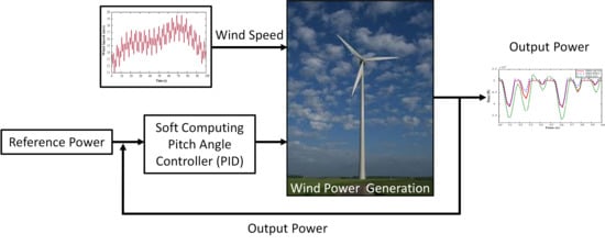
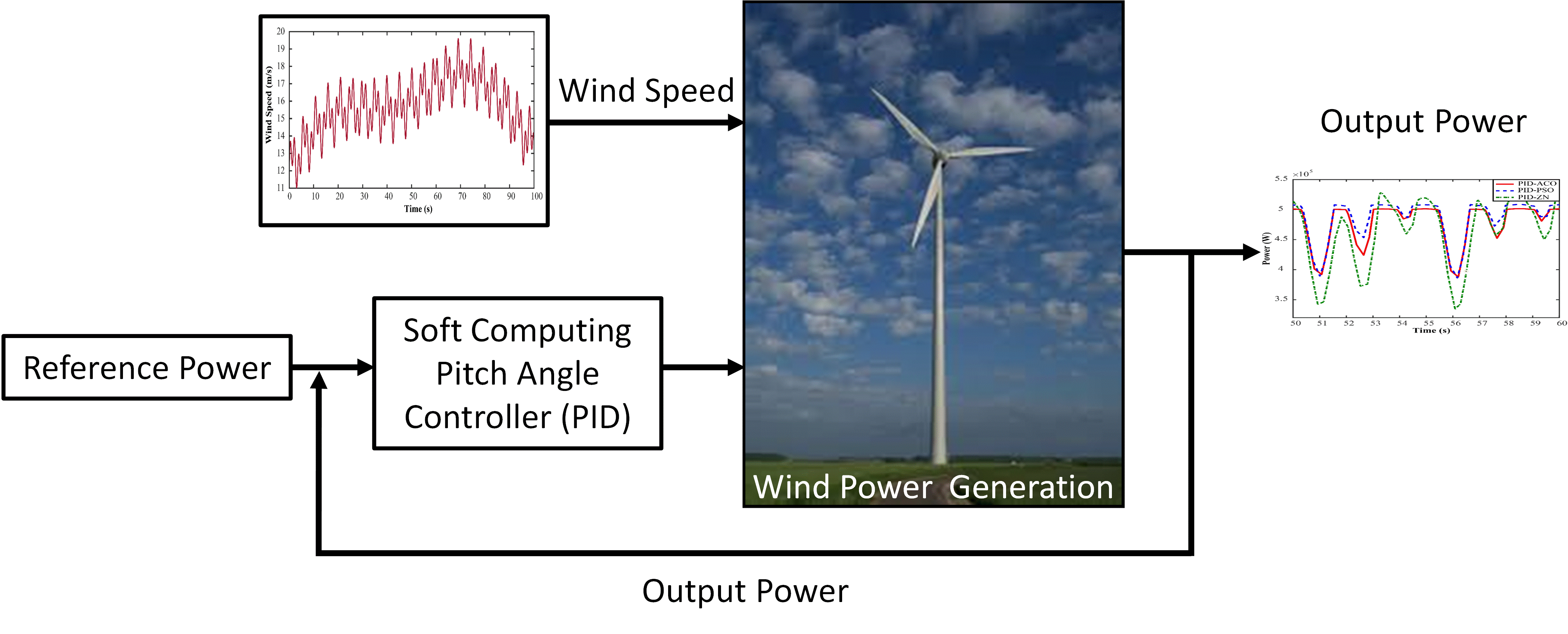
  • A robust pitch angle control strategy is proposed.
  • The proposed system is simulated under a wide range wind speeds, and its results are compared with those of a PID-ZN controller and PID-PSO to verify its effectiveness.
  • PID controller parameters are optimised using nature-inspired optimization methods, i.e., ACO and PSO.
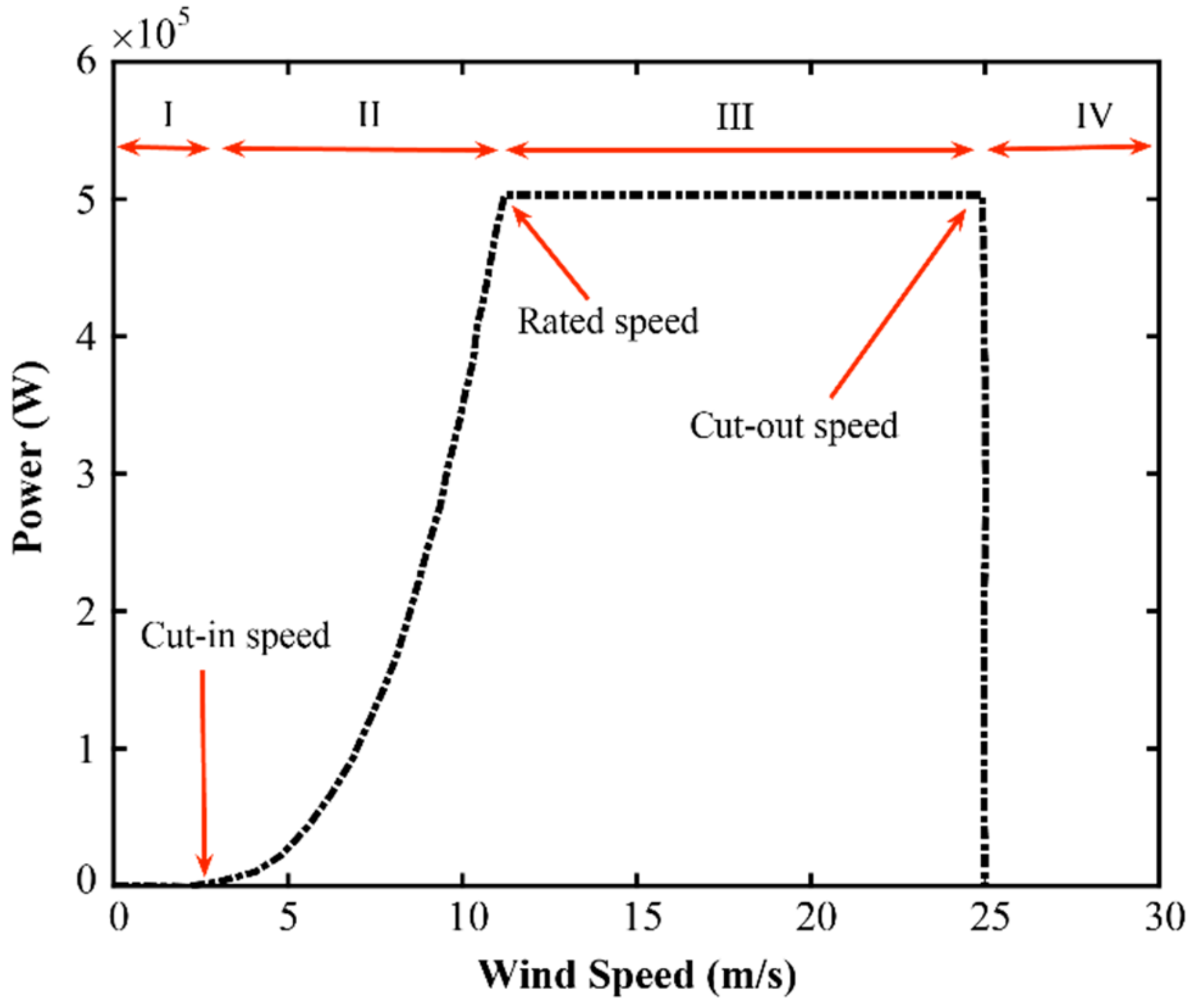
  • There are three modes of WPG under variable wind speed, namely P r e f e r e c n e   < P g e n e r a t o r , P r e f e r e c n e   > P g e n e r a t o r , and P r e f e r e c n e   = P g e n e r a t o r are analyzed, which will increase the robustness of the proposed controller.

2. Materials and Methods

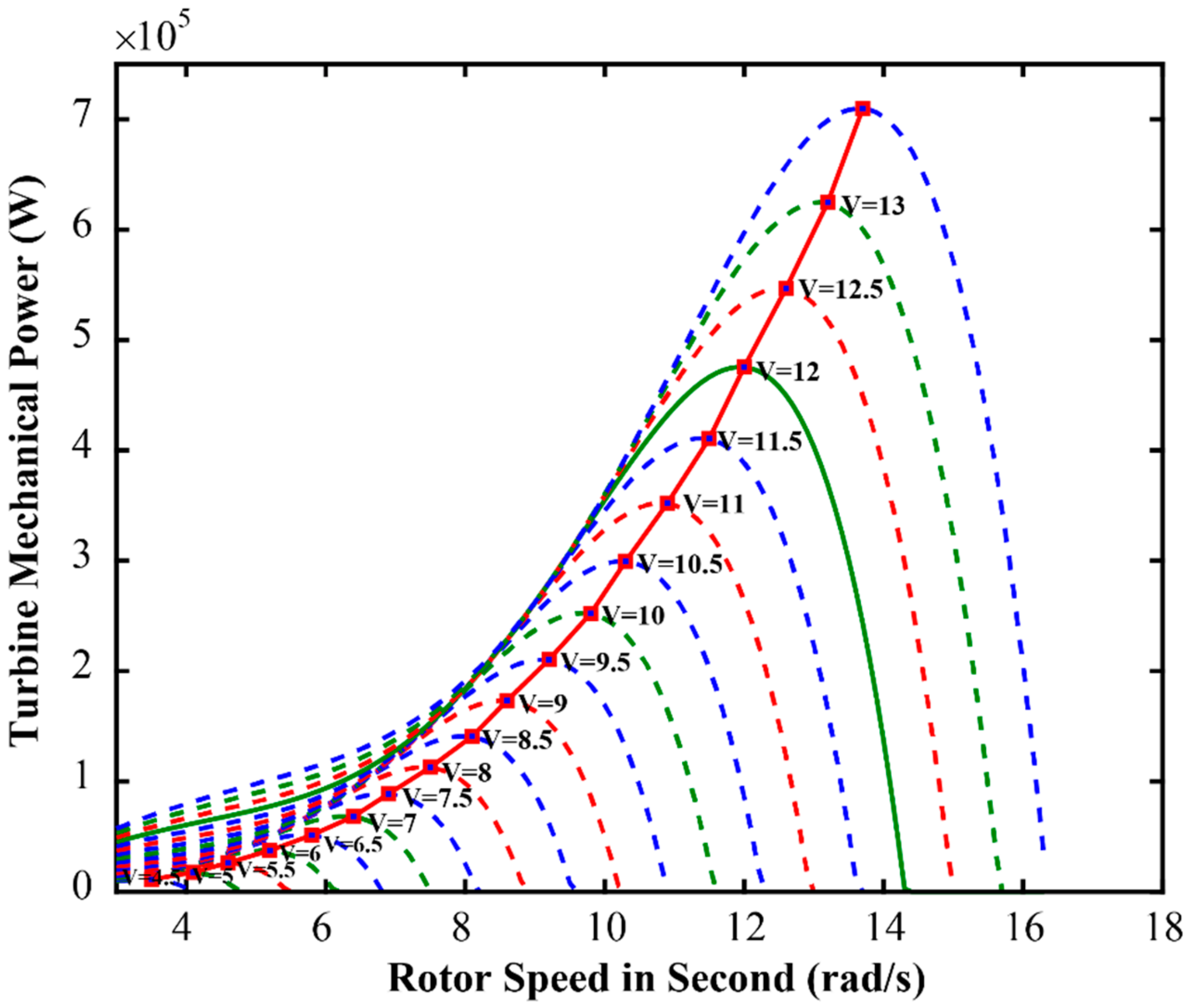
2.1. Wind Turbine Model

The progress of present commercial wind power generation has been continuously moving forward to the latest megawatt (MW) turbine. For horizontal axis wind turbines (HAWTs), parameters selection is challenging. The production of wind turbine power is influenced by various controlling parameters, such as wind velocity and the rotor speed of a WT [22]. The mechanical power equation of a WT can be written as [23,24,25]:
P m e c h a n i c a l = 0.5   ρ   C P   λ , β A s V w 3
where air density is expressed by ρ in kg / m 3 , wind velocity is expressed in V w ms 1 and C P is known as the rotor efficiency or power coefficient ( C P   ) . The approximate C P is defined by Equation (2).
C p λ , β = c 1 c 2 λ i c 3 β c 4 e c 5 λ i + c 6 λ
where c 1 = 0.5176 , c 2 = 116 , c 3 = 0.4 ,   c 4 = 5 , c 5 = 21 , and c 6 = 0.006 .
1 λ i = 1 λ + 0.08 β 0.035 β 3
Wind energy conversion is directly dependent on the C P of aerodynamic system, which is converted from mechanical energy into electrical energy. Moreover, the ratio of actual electric power produced by a WT and wind power into the turbine defines C P . German physicist Albert Betz calculated that wind speed will not be converted in kinetic energy by more than 59.3% [26]. The nonlinear parameters are λ , β defined by the tip speed ratio and pitch angle, respectively. In addition, the tip speed ratio can be expressed by
λ = ω r r V w
where r is the rotor radius, and ω r is the angular velocity of a wind turbine rotor. A nonlinear function C P and the tip speed ratio have been changed by the angular speed of the rotor and wind speed. Moreover, the power coefficient reaches the maximum when the pitch angle is 0 and the tip speed ratio λ is approximately 8, as shown in Figure 2. Since C p refers to the maximum efficiency of any wind turbine, hence, it is the optimal position of those parameters, and it is obtained by the proposed robust controller (PID-ACO).
In general, the wind turbine generator power has been changed by the wind speed and rotor speed, as shown in Figure 3. Besides, the turbine mechanical power is increased by the rotor and wind speed. Once the turbine reaches the rated power, a further increase of wind speed forces the turbine’s rotor to rotate above its rated speed. In this circumstance, the rotor speed and pitch angle need to be controlled accordingly; otherwise, turbine blades will be damaged.
On the other hand, the WT operating region has been divided into four areas, which are shown in Figure 4. In the first region, the wind speed reaches from 0 to the cut-in speed where the output power is 0, because the WT does not execute operation. The second region indicated that the wind speed is from cut-in to rated speed. In this region, the WT has started to execute its operation because it reaches the cut-in speed. The third region shows that the wind speed is between the rated and cut-out speed where WT can produce the rated wind power with a nominal wind speed. The fourth region is beyond the cut-out speed. Hence, in region IV, the wind speed will be increased, and the output power will increase as well. This increased power indicates the turbine’s output power above its rated level. Hence, the position of the blades will be changed. Therefore, pitch angle and power parameters need to be controlled for keeping the output power within the rated value.

2.2. Modeling of Permanent Magnet Synchronous Generator (PMSG)

PMSG produces electromagnetic torque, which can be expressed mathematically as [28]
T e = 3 P 2 ψ m i q s L d   L q i d s i q s
where the number of pole pairs of PMSG is P, the self-inductance of the PMSG dq axis, L d   a n d   L q are the d and q axes impedance, respectively, and magnetic flux linkage expressed by ψ m .
The stator current of the PMSG at the dq axis is expressed as i d s   a n d   i q s , respectively.
d i d s d t = R s L d i d s + L q L d ω r i d s v d s L d
d i q s d t = R s L q i q s + L d L q ω r i d s ω r   ψ m L q v q s L q
The resistance of stator winding of the PMSG is R s , the stator voltage of the PMSG at the dq axis is expressed v d s   a n d   v q s respectively, and the mathematical equation is expressed as [29]
v d s = R s i d s + ω r   L q i q s L d d i d s d t
v q s = R s i q s + ω r   L d i d s + ω r   ψ m L q d i q s d t
where the rotor speed of PMSG is ω r   rad / s . It can be expressed by Equation (10)
ω r   = P J T w T e
where J is the moment of inertia.

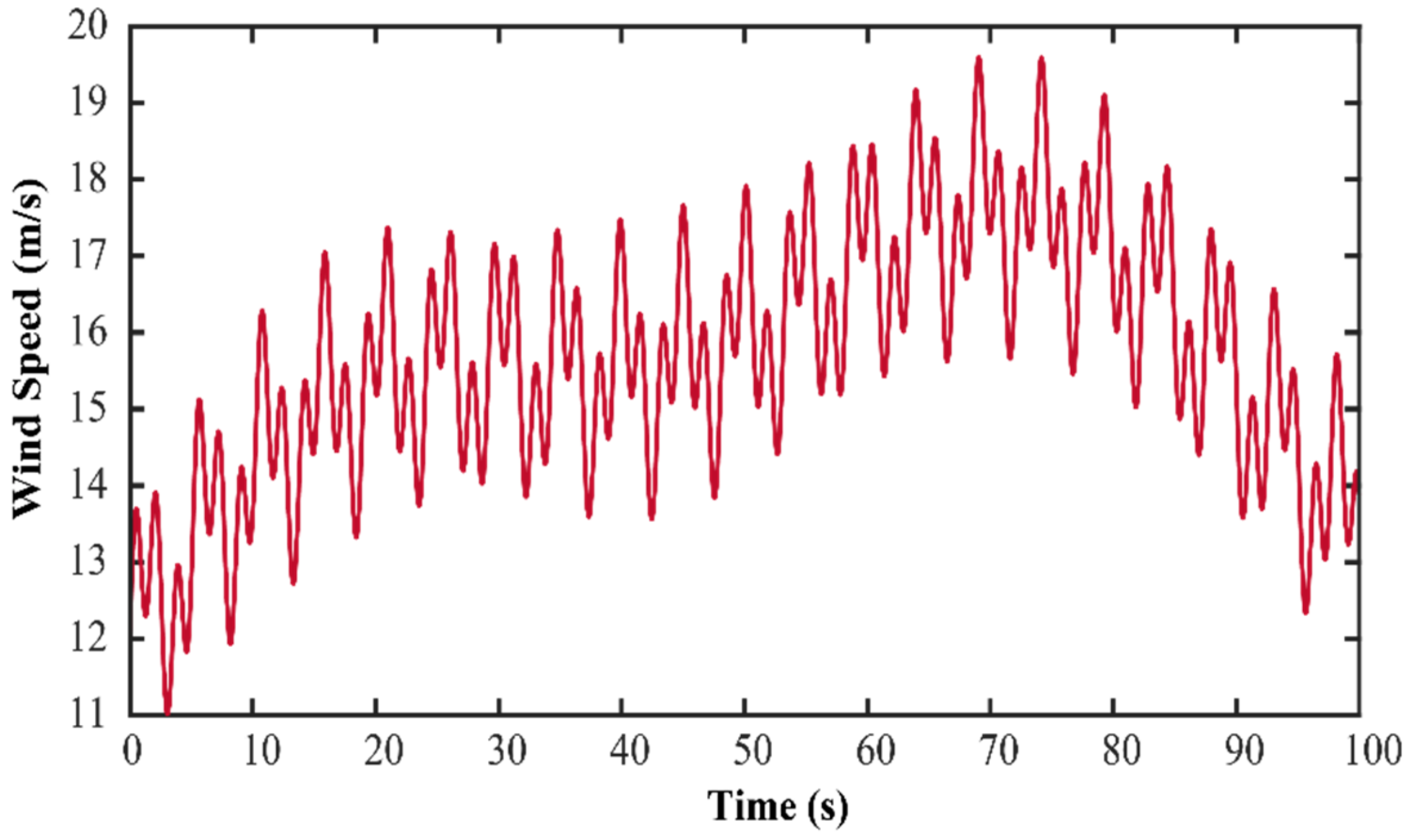
2.3. Profile of Wind Speed

The WT power is influenced by the chaotic and fluctuating wind speed. It is changing continuously. The magnitude of wind speed is random over any interval. For this study, the simulated wind speed is defined by the following Equation (11) [30].
V w = x + 1 sin 0.1047 t + 5 sin 0.2665 t + 1 sin 1.293 t + 1 sin 3.664 t
where x is the user-defined number. To simulated wind gusts, the magnitude and frequency of the sinusoidal fluctuations are increased.

2.4. Actuator Model

A pitch actuator is a system that can be electrically and hydraulically operated. The accuracy of an electrical actuator for speed control and position precision is satisfied. The blade of a WT can be set by a DC servo motor. A DC servo motor can be used as an actuator for wind turbine pitch angle control [31]. The transfer function of a DC servo motor can be expressed by Equation (12)
G s s = α τ s + β
where τ is the electrical time constant. The electrical time constant is much smaller than the mechanical time constant, and it is usually neglected. Both α and β are motor constants.
G p s = α s τ s + β
The position control of transfer function of a DC servo motor can be expressed by Equation (13). The value of the motor parameter is considered 1 due to the ease of computation. The reduced transfer function becomes as shown in Equation (14) by Equation (13)
G p s = α s s + 1 .

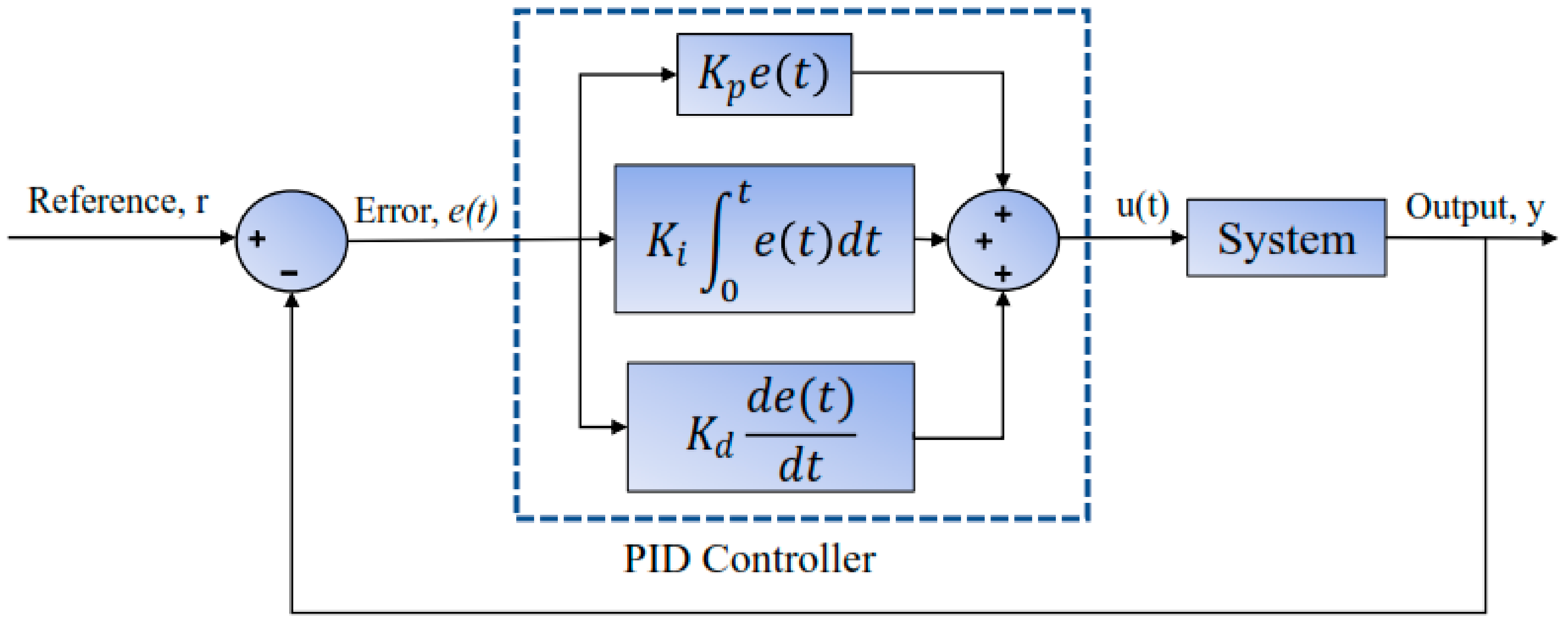
2.5. Controller Design

Proportional Integral Derivative Controller

The PID controller has been widely used in the industry for controlling purposes. The PID controller is selected in this study for some of its characteristics such as flexibility, reliability, and easy operation system. It consists of three control parameters: namely, proportional K p , integration K i , and derivative K d . Each controller parameter has an individual contribution for controlling any kind of system. A typical block diagram of a PID controller with a feedback loop is shown in Figure 4. In the closed-loop PID controller, the error of the system goes to the P, I, and D until getting the desired output.
Figure 5 shows that the sum of the control parameters is u t . The function of tracking errors e t can be referred by each and every control parameter, and these parameters are working independently. The mathematical model of PID control can be written as
u t = K p e t + K i 0 t e t d t + K d d e t d t .
The PID control parameters can be tuned by several methods—namely, trial and error, Ziegler–Nichols (Z-N), Tyreus–Luyben, Cohen–Coon, and auto tuned. In this study, Ziegler– Nichols (Z-N) has been adopted for controlling parameters tuning for the conventional PID controller. In addition, the tuning of the PID controller reaches a new era for soft computing techniques instead of conventional tuning. However, the best tuning method for a PID controller was proposed by Ziegler–Nichols in 1942 [32], which is called the ultimate gain method or continuous cycling method based on sustained oscillations. In addition, it consists of proportional, integral, and derivative control and is employed in a closed-loop system with step response. This controller is performed at the zero setting of integral k i and derivative k d . At the initial stage, the integral and derivative of the PID controller parameters were set on zero, and the proportional k d can be increasing or decreasing [33] from zero until the ultimate value ( K u = 28 ) , where the oscillations of the system will be constant ( K u = K p ) and the time period will be T u = 1.9 s . The k p , k i , and k d can be calculated by the ZN method (0.6* K u , 2 K p / T u , K p * T u /8). In the study, soft computer techniques—namely, ACO and PSO—have been used for PID parameter tuning by the optimization process [34,35].

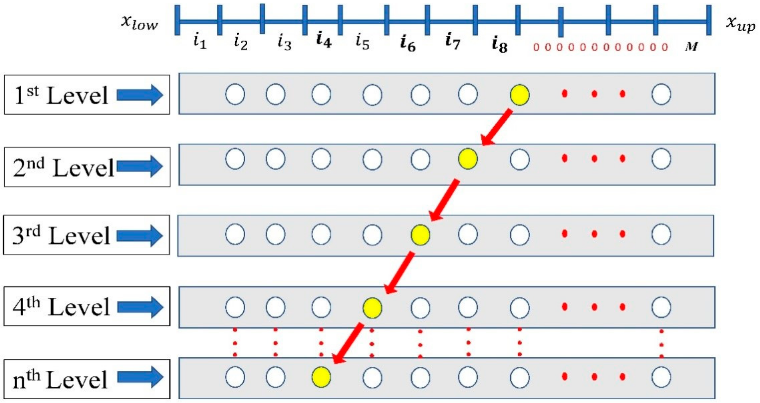
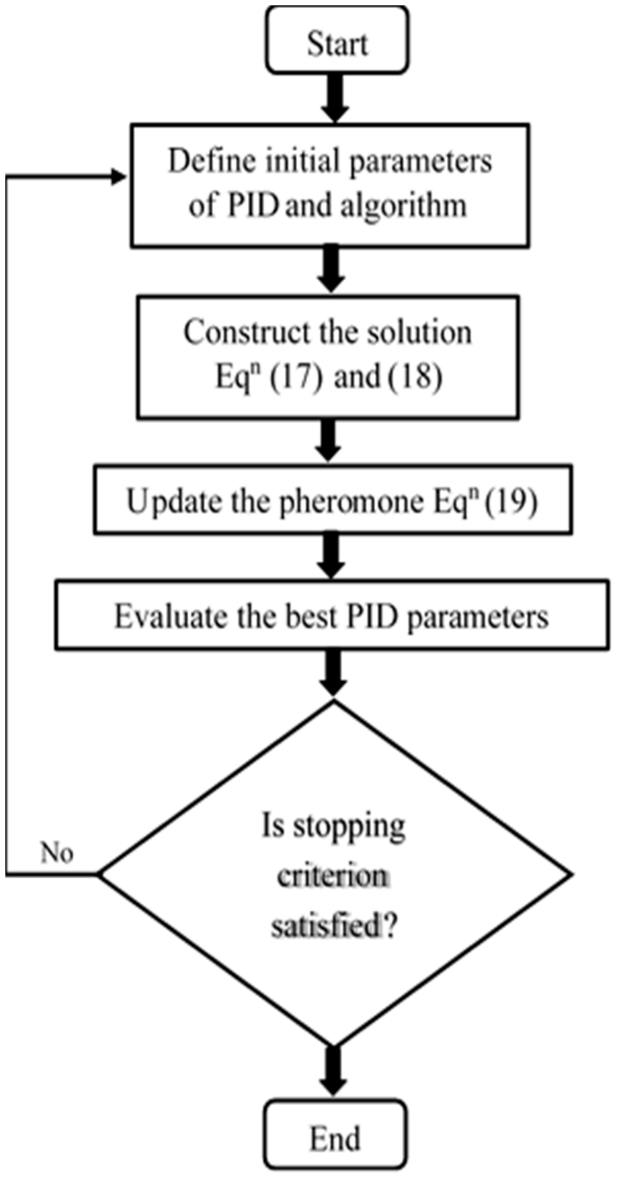
2.6. Ant Colony Algorithm

The technique of optimization for PID controller parameter tuning is common for the pitch angle control of a large wind turbine. The ACO algorithm is simple and effective for PID parameters tuning. The ACO algorithm was first introduced by Dorigo et al. [34], which is employed for our study for optimization purposes. The concept of the algorithm is inspired by the natural ant behavior of food searching by the shortest path. The problem of optimization can be solved by the support of artificial ant colony by using information through pheromones deposited on graph edges.
Assume the vector X = x 1 , x 2 , , x n represents the parameters of optimization, where the total number of parameters is n , and the lower and upper bounds are x i D x i = x i l o w , x i u p   with   i = 1 ,   2 , , n . The field definition D x i is divided by the subspace M and the node is defined by the middle of each subspace. In a single artificial ant k = 1 , 2 , N ant , where the maximum ant numbers are represented by N ant , the ants move from one node to another node, where P is the total node in each field definition D x i . For each subspace,
h i = x i _ u p x i _ l o w M
for each and every level, which has P nodes on it, and there are M × n nodes in total. k is the state vector of an ant whose entire tour is shown in Figure 6 with the travel index i 8 , i 7 , i 6 , . , i 4 . The travel index is directly dependent on the cumulative probability C P from the probability P i j of the ant k to move the i t h node on the j t h level. For example, if M = 10 , C P = 0.1 ,   0.2 ,   0.3 ,   0.4 ,   0.5 ,   0.6 ,   0.7 ,   0.8 ,   0.9 ,   1.0 , and the generated random number lies between 0.8 and 0.9, while the first travel index, i 8 , is chosen as 8 (eighth column of the C P ) [35]. Those processes have been continued until all the travel indexes are found. The values of the parameters X , held by an ant, are represented as
x 1 , x 2 , ,   x n = x 1 l o w + i 8 × h i , x 2 l o w + i 7 × h 2 , x 3 l o w + h 6 × i 6 , , x n l o w + h n × i n .
The rule of state transition of the ant k is defined as
P i j = τ i j i = 1 n τ i j
where the ant probability P i j moves to the i th node on the j th level. The pheromone at the node is τ i j . The pheromone is updated by using the following equation, when all the ants finished their tours.
τ i j = 1 ρ τ i j + Q f b e s t
where the pheromone decay parameter range is 0 < ρ < 1 , Q is the quantity of pheromones laid by an ant per cycle, τ 0   is a constant for the initial value of τ i j (for initialization, τ i j on the right-hand side is set to be τ 0 ), and f best is a function of the objective. From the objective function, the best value is given by an ant in each searching period [37].
As shown in Figure 6, the algorithm starts with the initialization of the pheromone track. The desired optimization objective function u t is calculated for each ant, and the maximum value is stored as f o . The construct of an ant-completed solution of an objective problem for each iteration according to the state transition of probabilistic rule is shown in Equation (18). Regarding the quantity of pheromones at the third step, updating the role of a global pheromone is applied in two phases. First, there is an evaporation phase, where a fraction of the pheromone evaporates, and then there is a reinforcement phase, where each ant deposits an amount of pheromone that is proportional to the objective function of its solution. The process is iterated until the stopping criterion is satisfied, as shown in Figure 6. The flow chart of ACO algorithm is illustrated in Figure 7.

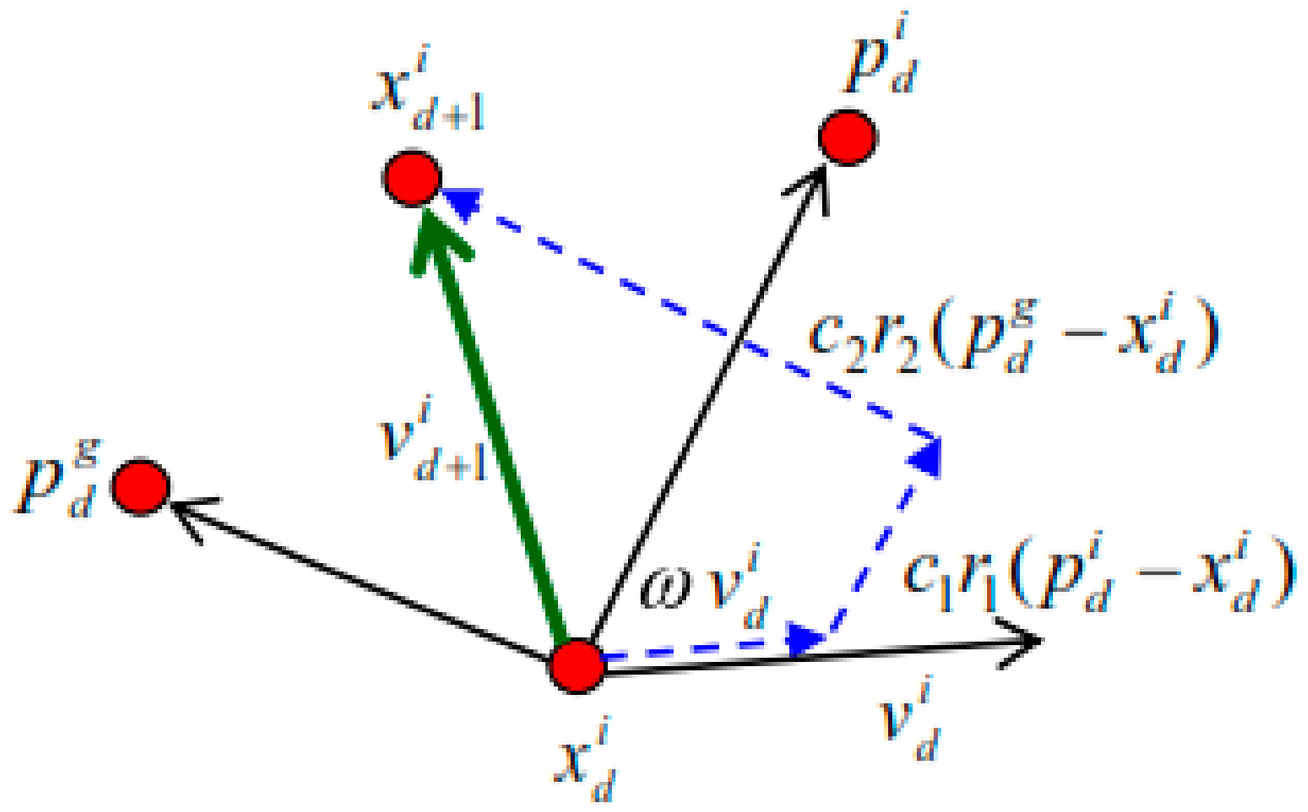
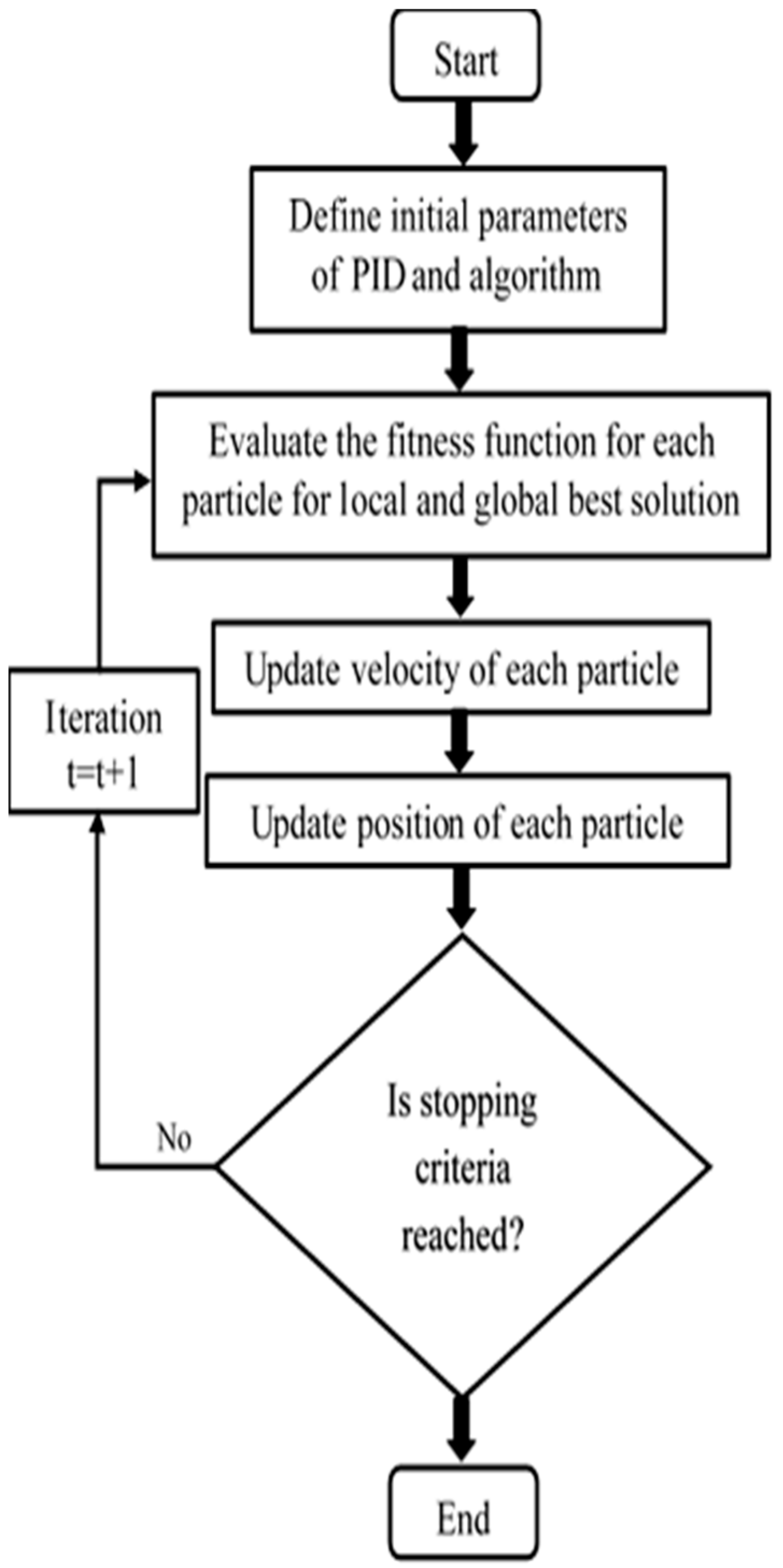
2.7. Particle Swarm Optimization

PSO is one of the most appealing and widely used meta-heuristics proposed by Kennedy and Eberhard in 1995 [38,39]. This algorithm is capable of solving more complex problems because of its meta-heuristics nature. It is simple and easy to implement. The fundamentals of PSO are inspired by swarm behavior. This meta-heuristic is comprised of multiple particles. Each particle consists of three components: position, current objective value, and velocity. It conserves the global best value, which is related to the best objective value. The global best value is also related to the global best position at which the global best value is achieved [38].
At the starting period, the random population of swarms is generated with random position vectors and the velocity of vectors. The best position of each particle is according to the best fitness value obtained by the particle time. After iteration, the new positions and velocities to the particle for the next fitness evolution are calculated by the following equations [40].
v i d t + 1 = ω × v i d t + c 1 × φ 1 × p i d x i d t + c 1 × φ 2 × p g d x i d t
x i d t + 1 = x i d t + v i d t + 1
where ω = inertia weight; it is inseparable because t plays a vital role in guaranteeing the convergent behaviors of φ1 and φ2; φ1 and φ2 = uniform and random numbers with interval (0,1); c1 and c2 = constants of acceleration; pi(pbest) = the personal best particle; and pg(gbest) = the best position of the particle.
The position of each parameter is illustrated in Figure 8. The first part of Equation (20) represents the previous velocity. The required momentum for the particles to roam across the search space comes from this part of the equation. The second part of Equation (20) stands for the personal thinking of each particle, which is known as the “cognitive” part or component. The particles are encouraged to move toward their own best positions with the help of the cognitive component. The third part of Equation (20) helps find the optimal global solution, which is known as the “social” component. This part repeatedly drags the particles in the direction of the global best particle found so far. In addition, it represents the effect of the collaboration of the particles. The flow chart of PSO is shown in Figure 9.

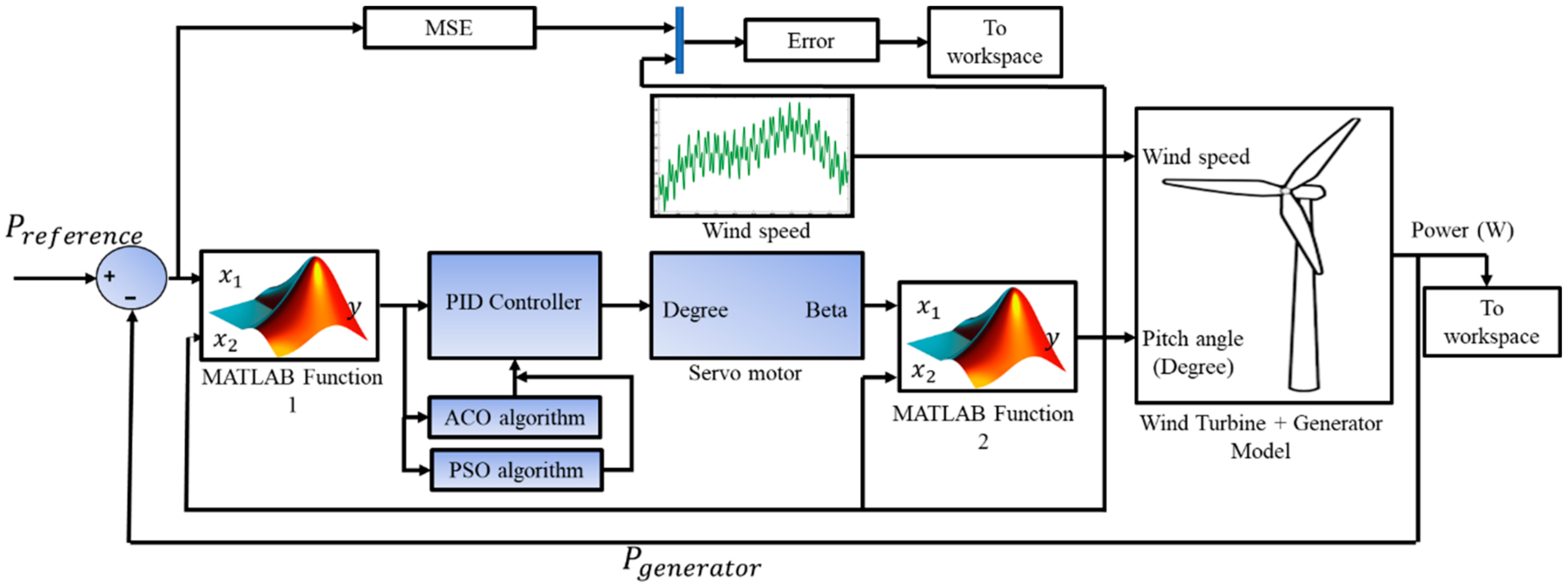
3. Simulation Evaluation

The design and development of a pitch angle controller of a WT system are important to increase the reliability and efficiency of WT power. It is also minimizing the effect of structure on the WT and wind power fluctuation. The mathematical modeling of WPG is important to develop a vital control system with a PID controller. The WPG and controllers have been developed in MATLAB/Simulink. The overview of the system in MATLAB/Simulink is presented in Figure 10.
At the initial stage, the mathematical modeling of a wind turbine and generator have been embedded from Equation (1) to Equation (10). The wind speed and pitch angle of the WT blade are the exigent inputs of the wind turbine plus a generator block, as shown in Figure 10. The wind speed, which is the vital input parameter in the system, is simulated by Equation (5), as shown in Figure 11.
The parameters of the wind turbine and generator are shown in Table 1. The DC servo motor has been used to maintain the angular position of the WT blade by Equation (14). Two MATLAB/Simulink functions are used, and the functions are operated for almost similar tasks. The MATLAB Function 1 is used as a conditional function so that the wind speed remains between the cut-in speed and nominal speed by using P r e f e r e n c e and P g e n e r a t o r power, which are used as the input of Function 1. On the other hand, the MATLAB Function 2 controls the wind speed between nominal and cut-out. The reference rated power P r e f e r e n c e is the desired WT power. The error signal can be obtained from the reference power to the wind turbine generator. The PID control block obtains an error signal when the wind speed is above the nominal speed.
The PID controller parameters have been optimized by ACO and PSO algorithms through MATLAB. At first, there are some ACO and PSO parameters selected for conducting optimization processes; those are shown in Table 2. After starting the process of the model, the system evaluates the objective/cost function that refers to the PID controller Equation (15). The cost function of the ACO and PSO is the error between the desired power and the actual power. After each iteration, the optimum values of the PID parameters are updated and stopped when the maximum iteration number is reached or when the objective function criterion is satisfied. The search range for PID parameters K p , K i and K d was selected randomly between [ 100 , 1 × 10 13 , 6 × 10 07 ] and [100, 1 × 10 03 , 6 × 10 01 ]. The optimum PID parameters of three controllers are shown in Table 3.
The calculation of pitch angle that has been sent to the servo motor block for adjusting the blade pitch by the controller of PID-ACO and PID-PSO is shown in Figure 12. The output of the servo motor is used as the pitch angle of the wind power conversion system. For controlling the pitch angle, the output power will be maintained within nominal power. The Mean Squared Error (MSE) that has been collected from the MATLAB workspace is sent by an error signal using ACO and PSO algorithms. The MSE error is shown in Figure 13.

4. Result Analysis

In this study, we have proposed three hybrid pitch angle controllers for automatic power adjusting within the rated power of a 500 kW WTG system at the operating regions of WT under variable wind speeds. The WTG system consists of WT and PMSG. The study was developed in the MATLAB/Simulink environment with validated parameters for the WT and generator, which are shown in Table 1. The fluctuating simulated wind speed applied to the WPG system is divided into four regions. Three preferential modes have been considered to determine the performance accuracy of the proposed pitch angle controllers and automatic power adjusting within the rated power of WPG. These modes are as follows:
Mode I: P r e f e r e c n e   < P g e n e r a t o r .
In this condition, the generator power is lower than the reference power. Due to the low wind speed, the WT blades cannot capture a higher cut-out wind speed. This is operation region II of the wind turbine, which is shown in Figure 4. In addition, the power generation will be decreasing, because the rotor rotates below the rated speed of the rotor. WPG is not sufficient for the load demand, and it can be said that it is not efficient. At the situation, the pitch angle controller is working actively within approaches to 00. Approaching 00 is the optimal value for maximum power production by the wind turbine.
Mode II: P r e f e r e c n e   > P g e n e r a t o r .
In this condition, the generator power is lower than the reference power. Due to the low wind speed, the WT blades cannot capture higher wind speed. This is operation region I of the wind turbine, which is shown in Figure 4. In addition, the power generation will be decreasing because the rotor rotates below the rated speed of the rotor. The WPG is not sufficient for the load demand, and it can be said that it is not efficient. In this situation, the pitch angle controller is working actively within approaches to 00. Approaching 00 is the optimal value for maximum power production by the wind turbine.
Mode III: P r e f e r e c n e   = P g e n e r a t o r .
In this situation, the generated and reference power are balanced. The flow of wind is within the rated speed. In addition, the maximum power generation occurs in the situation, and all parts of the WTG are working safely. The pitch controller will work at a nominal angle. Operation region III of the wind turbine is shown in Figure 4. Region III is the safe and optimal region for the wind power generation of any WT.
The total electrical wind power is produced by the WPG system shown in Figure 14a,b, which shows wind power at the zoomed condition. Figure 14b shows that PID-ACO keeps the generated wind power below 5.01 × 10 5 W, which is very near the desired output power ( 5 × 10 5 W ) of the WTG. However, the PID-PSO controller gives an output power (OP) value that is slightly higher than the desired power value. It can be also noticed in Figure 14a that the output power of the WTG with the PID-ZN controller is fluctuating at different points, which are higher than the PID-PSO and PID-ACO controllers’ output power. In addition, the output power of WTG by PID-ZN and PID-PSO controllers show higher than the desired output power of WTG. Based on the above discussion, it can be concluded that the hybrid ACO-PID controller provided a promising result in comparison to PID-ZN and PID-PSO controllers regarding rated wind turbine power under variable wind speed. As we know, the PID controller parameters can provide the desired power of WTG by the accurate pitch angle controlling, but it does not occur. So, the ZN and PSO were not tuning the parameters properly based on Figure 12 and Figure 14. Figure 12 shows the pitch angle by the proposed controllers. Figure 12 shows the maximum pitch angle offered by the PID-ZN and PID-PSO respectively to compare them with PID-ACO. In this circumstance, the WPG provides the higher desired power under variable wind speed, so, except for PID-ACO, those controllers are not working properly.
The mean square error (MSE) of the ACO and PSO algorithms is shown in Figure 13. It is the convergence curve of the proposed algorithm. Figure 13 shows the number of iterations of ACO and PSO at the x-axis and MSE at the y-axis. After analysis, Figure 12 shows that the ACO algorithm error reaches 0 after 21 iterations, and PSO reaches 0 at 43 iterations. The ACO algorithms show a better result regarding MSE in comparison with the PSO algorithm. Its reflection of the MSE error is displayed in the computational time of the algorithms.
The computational time of the algorithms refers to how much time it takes the algorithms to complete the work. Figure 15 shows the computational time of the PSO and ACO algorithms for the PID parameters optimization processes. The PSO algorithm takes 0.43 s to complete the assigned work, whereas the execution time of the ACO algorithm is 0.21 s: half that of the PSO algorithm. Based on the computational time, the performance of the ACO algorithm is more effective than that of the PSO algorithm.
The root mean square error is between the reference/desired power of the proposed system and the generator power. RMS error comparisons among the three controlling methods are shown in Table 4. Based on the error calculation, it can be concluded that the PID-ACO controller provides the lowest RMS error, which is 0.00035, compared to the PID-ACO and PID-ZN controllers, which are 0.0020 and 0.0035, respectively.

5. Conclusions

The purpose of pitch control is to maintain the optimum blade angle to achieve a specific power output. It is crucial to control parameters to ensure low maintenance costs and the efficient performance of a wind turbine. In this paper, a PID-ACO-based robust pitch angle controller is designed for a wind turbine to obtain stable rated WT output power from the fluctuating wind speed. The PID controller is tuned by using the ACO method and the response of the system is able to achieve the result near the desired output. The comparative analysis of PID controllers reveals that the ACO-PID method is slightly better than PID-PSO, and it is far better than PID-ZN controller tuning by the trial and error method. The results of the ACO-PID controller were also compared with the PID controller and PID-PSO, which showed a significant reduction of output power fluctuation of wind turbines. It can be evident that the utilization of the proposed PID-ACO control system improves the quality and amplitude of the output power from the WTG system.
Moreover, it is more capable of providing better efficiency due to its lower dependency on randomness. Simultaneously, the PSO algorithm requires a higher computation time to optimize the value of a system, and the Z-N tuning method may not provide the optimum performance or best disturbance tolerance. The proposed intelligence pitch angle controller of the wind turbine blade meets a promising result that can be protected from the fluctuating wind speed. Besides, the lifetime of the WT and the reduced production cost of wind power will increase linearly.
The current study forms a basis from which future endeavors may analyze the wind turbine’s pitch angle control in greater detail. It would be fascinating to incorporate a hybrid algorithm (ACO-PSO) to the PID tuning for dynamic wind turbine controlling as a future extension of this study.

Author Contributions

All authors discussed and agreed on the idea and contribution. Writing the manuscript, mathematical modeling, and simulation, M.R.S.; optimizing the model, S.J. and C.W.T.; revisions and discussion of the results, M.U., M.F.R. and G.S. All authors have read and agreed to the published version of the manuscript.

Funding

Authors would like to express their gratitude to the Ministry of Higher Education of Malaysia and University Malaya (ERGS No. ER0142013A, RP015C-13AET and High Impact Research Grant (HIR-D000006-16001)) for funding and providing facilities to conduct the research.

Conflicts of Interest

The authors declare no conflict of interest.

References

  1. Shoeb, M.A.; Shafiullah, G.M. Renewable energy integrated islanded microgrid for sustainable irrigation—A Bangladesh perspective. Energies 2018, 11, 1283. [Google Scholar] [CrossRef] [Green Version]
  2. Sarkar, R.; Julai, S.; Hossain, S.; Chong, W.T.; Rahman, M. A comparative study of activation functions of nar and narx neural network for long-term wind speed forecasting in malaysia. Math. Probl. Eng. 2019, 2019. [Google Scholar] [CrossRef]
  3. Astolfi, D.; Castellani, F.; Lombardi, A.; Terzi, L. About the extension of wind turbine power curve in the high wind region. J. Sol. Energy Eng. 2019, 141. [Google Scholar] [CrossRef]
  4. Assareh, E.; Biglari, M. A novel approach to capture the maximum power from variable speed wind turbines using pi controller, rbf neural network and gsa evolutionary algorithm. Renew. Sustain. Energy Rev. 2015, 51, 1023–1037. [Google Scholar] [CrossRef]
  5. Chen, Y.-J.; Shiah, Y. Experiments on the performance of small horizontal axis wind turbine with passive pitch control by disk pulley. Energies 2016, 9, 353. [Google Scholar] [CrossRef] [Green Version]
  6. Leithead, W.; Connor, B. Control of variable speed wind turbines: Design task. Int. J. Control. 2000, 73, 1189–1212. [Google Scholar] [CrossRef]
  7. Yin, X.-X.; Lin, Y.-G.; Li, W.; Gu, Y.-J.; Wang, X.-J.; Lei, P.-F. Design, modeling and implementation of a novel pitch angle control system for wind turbine. Renew. Energy 2015, 81, 599–608. [Google Scholar] [CrossRef]
  8. Dueñas-Osorio, L.; Basu, B. Unavailability of wind turbines due to wind-induced accelerations. Eng. Struct. 2008, 30, 885–893. [Google Scholar] [CrossRef]
  9. Ekelund, T. Speed control of wind turbines in the stall region. In Proceedings of the Third IEEE Conference on Control Applications,, Glasgow, UK, 24–26 August 1994; Volume 1, pp. 227–232. [Google Scholar]
  10. Shaked, U.; Soroka, E. On the stability robustness of the continuous-time lqg optimal control. IEEE Trans. Autom. Control. 1985, 30, 1039–1043. [Google Scholar] [CrossRef]
  11. Kong, Y.; Wang, Z.; Yuan, H. A new fuzzy sliding-mode control for mw variable speed-variable pitch wind turbine. In Proceedings of the 7th IET International Conference on Advances in Power System Control, Operation and Management (APSCOM 2006), Hong Kong, China, 30 October–2 November 2006. [Google Scholar]
  12. Amandola, C.; Gonzaga, D. Fuzzy-logic control system of a variable-speed variable-pitch wind-turbine and a double-fed induction generator. In Proceedings of the Presented at Intelligent Systems Design and Applications, 2007. ISDA 2007., Rio de Janeiro, Brazil, 20–24 October 2007; pp. 252–257. [Google Scholar]
  13. Gao, R.; Gao, Z. Pitch control for wind turbine systems using optimization, estimation and compensation. Renew. Energy 2016, 91, 501–515. [Google Scholar] [CrossRef]
  14. Perng, J.-W.; Chen, G.-Y.; Hsieh, S.-C. Optimal pid controller design based on pso-rbfnn for wind turbine systems. Energies 2014, 7, 191–209. [Google Scholar] [CrossRef] [Green Version]
  15. Zhang, L.; Li, H.; Chunliang, E.; Li, J.; Xu, H. Pitch control of large scale wind turbine based on fuzzy-pd method. In Proceedings of the Presented at Electric Utility Deregulation and Restructuring and Power Technologies, DRPT 2008, Nanjing, China, 6–9 April 2008; pp. 2447–2452. [Google Scholar]
  16. Dou, Z.; Cheng, M.; Ling, Z.; Cai, X. An adjustable pitch control system in a large wind turbine based on a fuzzy-pid controller. In Proceedings of the Presented at Power Electronics Electrical Drives Automation and Motion (SPEEDAM), Pisa, Italy, 14–16 June 2010; pp. 391–395. [Google Scholar]
  17. Iqbal, A.; Ying, D.; Saleem, A.; Hayat, M.A.; Mateen, M.; Javed, M.S. Proposed fls-pid wind turbine pitch control for efficacious output. In Proceedings of the International Symposium on Recent Advances in Electrical Engineering (RAEE), Islamabad, Pakistan, 28–29 August 2019. [Google Scholar]
  18. Civelek, Z.; Çam, E.; Lüy, M.; Mamur, H. Proportional–integral–derivative parameter optimisation of blade pitch controller in wind turbines by a new intelligent genetic algorithm. IET Renew. Power Gener. 2016, 10, 1220–1228. [Google Scholar] [CrossRef]
  19. Civelek, Z.J.E.S.; Technology, A.I.J. Optimization of fuzzy logic (takagi-sugeno) blade pitch angle controller in wind turbines by genetic algorithm. Eng. Sci. Technol. Int. J. 2020, 23, 1–9. [Google Scholar] [CrossRef]
  20. Karad, S.; Thakur, R. Comparative analysis of fractional-order pid controller for pitch angle control of wind turbine system. In Computing in Engineering and Technology; Springer: Berlin/Heidelberg, Germany, 2020; pp. 647–657. [Google Scholar]
  21. Gaing, Z.-L. A particle swarm optimization approach for optimum design of pid controller in avr system. IEEE Trans. Energy Convers. 2004, 19, 384–391. [Google Scholar] [CrossRef] [Green Version]
  22. Lanzafame, R.; Messina, M. Horizontal axis wind turbine working at maximum power coefficient continuously. Renew. Energy 2010, 35, 301–306. [Google Scholar] [CrossRef]
  23. Selig, M.S.; Coverstone-Carroll, V.L. Application of a genetic algorithm to wind turbine design. J. Energy Resour. Technol. 1996, 118, 22–28. [Google Scholar] [CrossRef] [Green Version]
  24. Jureczko, M.; Pawlak, M.; Mężyk, A. Optimisation of wind turbine blades. J. Mater. Process. Technol. 2005, 167, 463–471. [Google Scholar] [CrossRef]
  25. Khalfallah, M.G.; Koliub, A.M. Suggestions for improving wind turbines power curves. Desalination 2007, 209, 221–229. [Google Scholar] [CrossRef]
  26. Dabiri, J.O. Theoretical framework to surpass the betz limit using unsteady fluid mechanics. Phys. Rev. Fluids 2020, 5, 022501. [Google Scholar] [CrossRef] [Green Version]
  27. Bashetty, S.; Guillamon, J.I.; Mutnuri, S.S.; Ozcelik, S.J.E. Design of a robust adaptive controller for the pitch and torque control of wind turbines. Energies 2020, 13, 1195. [Google Scholar] [CrossRef] [Green Version]
  28. Slimen, A.; Tlijani, H.; Dhaoui, M.; Younes, R.B. Control of wind turbine based on pmsg using pitch angle control. In Modeling, Identification and Control Methods in Renewable Energy Systems; Springer: Berlin/Heidelberg, Germany, 2019; pp. 151–165. [Google Scholar]
  29. Mousa, H.H.; Youssef, A.-R.; Mohamed, E.E.M. Optimal power extraction control schemes for five-phase pmsg based wind generation systems. Eng. Sci. Technol. Int. J. 2020, 23, 144–155. [Google Scholar]
  30. Tran, D.-H.; Sareni, B.; Roboam, X.; Espanet, C. Integrated optimal design of a passive wind turbine system: An experimental validation. IEEE Trans. Sustain. Energy 2010, 1, 48–56. [Google Scholar] [CrossRef] [Green Version]
  31. Qi, Y.; Meng, Q. The application of fuzzy pid control in pitch wind turbine. Energy Procedia 2012, 16, 1635–1641. [Google Scholar] [CrossRef] [Green Version]
  32. Valério, D.; da Costa, J.S. Tuning of fractional pid controllers with ziegler–nichols-type rules. Signal. Process. 2006, 86, 2771–2784. [Google Scholar] [CrossRef]
  33. Rahman, M.; Ong, Z.C.; Chong, W.T.; Julai, S.; Ng, X.W. Wind turbine tower modeling and vibration control under different types of loads using ant colony optimized pid controller. Arab. J. Sci. Eng. 2019, 44, 707–720. [Google Scholar] [CrossRef]
  34. Dorigo, M.; Gambardella, L.M. Ant colonies for the travelling salesman problem. BioSystems 1997, 43, 73–81. [Google Scholar] [CrossRef] [Green Version]
  35. Jalil, N.; Julai, S.; Ramli, R. Parametric modelling of flexible plate structures using continuous ant colony optimization. J. Simul. 2015, 9, 223–231. [Google Scholar] [CrossRef]
  36. Sarkar, M.; Julai, S.; Tong, C.W.; Toha, S.F. Effectiveness of nature-inspired algorithms using anfis for blade design optimization and wind turbine efficiency. Symmetry 2019, 11, 456. [Google Scholar] [CrossRef] [Green Version]
  37. Galdi, V.; Piccolo, A.; Siano, P. Designing an adaptive fuzzy controller for maximum wind energy extraction. IEEE Trans. Energy Convers. 2008, 23, 559–569. [Google Scholar] [CrossRef]
  38. Bai, Q. Analysis of particle swarm optimization algorithm. Comput. Inf. Sci. 2010, 3, 180. [Google Scholar] [CrossRef] [Green Version]
  39. Kennedy, J. Handbook of Nature-Inspired and Innovative Computing; Springer: Berlin/Heidelberg, Germany, 2006; pp. 187–219. [Google Scholar]
  40. Shi, Y.; Eberhart, R. A modified particle swarm optimizer. In Proceedings of the IEEE International Conference on Evolutionary Computation Proceedings, IEEE World Congress on Computational Intelligence (Cat. No. 98TH8360), Anchorage, AK, USA, 4–9 May 1998; pp. 69–73. [Google Scholar]
  41. Zhou, W.; Zou, C.; Li, J.; Li, G. Dynamic modeling and coordinate control for an engine-generator set. In Proceedings of the 19th Asia Pacific Automotive Engineering Conference (SAE)-China Congress: Selected Papers; Springer: Berlin/Heidelberg, Germany, 2017; pp. 1015–1033. [Google Scholar]
Figure 1. Block diagram of wind power generation (WPG).
Energies 13 03622 g001
Figure 2. Power coefficient vs. tip speed ratio for different pitch angles [27].
Energies 13 03622 g002
Figure 3. Turbine mechanical power curve vs. rotor speed under variable wind speeds.
Energies 13 03622 g003
Figure 4. Wind power curve vs. wind speed.
Energies 13 03622 g004
Figure 5. A typical block diagram of a proportional–integral–derivative (PID) controller with feedback loop.
Energies 13 03622 g005
Figure 6. State space of ant colony optimization (ACO) [36].
Energies 13 03622 g006
Figure 7. Flow chart of the ACO algorithm.
Energies 13 03622 g007
Figure 8. Particle swarm optimization (PSO) algorithms [36].
Energies 13 03622 g008
Figure 9. Flow chart of the PSO algorithm.
Energies 13 03622 g009
Figure 10. Wind turbine MATLAB/Simulink model.
Energies 13 03622 g010
Figure 11. Wind speed profile.
Energies 13 03622 g011
Figure 12. Pitch angle of the wind turbine blade.
Energies 13 03622 g012
Figure 13. Convergence curve of ACO and PSO.
Energies 13 03622 g013
Figure 14. (a) Output wind power generation by the proposed controller; (b) Zoomed figure region.
Energies 13 03622 g014
Figure 15. Computational time of the ACO and PSO algorithms.
Energies 13 03622 g015
Table 1. Parameters of wind turbine system [18,19,41].
Wind Turbine Parameters
ParametersValueUnit
Nominal output power500kW
Cut-in wind speed3m/s
Working modeNetwork connection -
Nominal wind speed12 m/sm/s
Cut-out wind speed25 m/sm/s
Rotor diameter48 mm
Sweep area 1810 m 2 m 2
Blade number3-
Nominal rotor speed30 rpmrpm
Rotor speed range10–30 rpmrpm
Gear box rate01:50-
Generator number1-
Generator typePMSG-
Generator nominal output500kW
Generator nominal cycle1500rpm
Generator voltage690 VV
Nominal frequency 50Hz
d-axis inductance 0.0045mH
q-axis inductance 0.0045mH
d-axis resistance0.017
q-axis resistance0.017
Generator inertia 0.489 kgm 2
Permanent magnet linkage flux0.175Wb
Pole pairs 6-
Table 2. Specification of algorithms (ACO and PSO).
AlgorithmsParametersValue
ACONumber of iterations100
Number of ants50
Node10
Pheromone quantity (Q)100
Decay Parameter8.5
PSONumber of iterations100
Population size10
Constants of acceleration ( c 1 and c 2 )1.5
Minimum inertia weight w m i n 0.9
Maximum inertia weight w m a x 0.4
Dimension03
Table 3. K p ,   K i and K d parameters of Ziegler–Nichols (ZN), PSO, and ACO.
Controller GainPID-ZN MethodPSO MethodACO Method
K p 3.18 × 10 6 10.25 × 10 3 11.4 × 10 1
K i 4.5 × 10 6 3.69 × 10 10 1.35 × 10 11
K d 8.50 × 10 9 5.88 × 10 2 6.254 × 10 3
Table 4. Root mean square error (RMS) error of proposed PID-ACO to compare with PID-ZN and PID-PSO.
MethodsRoot Mean Square (RMS)
PID-ACO0.00036
PID-PSO0.0020
PID-ZN0.0035

