1. Introduction
Nowadays, the dominant fuel used for electricity generation worldwide is coal. Energy production based on coal is inevitably connected with several issues, notably with a generation of vast amounts of combustion by-products [
1,
2]. The main coal combustion by-product is fly ash and in many countries its utilisation level is low. Fly ash is an inhomogeneous material, concerning its chemical composition and physical parameters such as density and grain size. According to the practice of sustainable waste management, the whole mass of the fly ash should be divided into fractions of different chemical and physical properties to expand potential opportunities for its use. A specific application may be found for each particular fraction and this would lead to an increase in the market value of fly ash [
3]. The low density (<1 g/cm
3) aluminosilicate microspheres (MS), often called cenospheres, are an example of a valuable fraction. There are numerous applications of such material that have been recently studied e.g. cement-based composites [
4], particulate reinforced metal matrix composites [
5], polymer composites [
6,
7,
8,
9], a catalytic support [
10,
11,
12,
13] or a fluidised bed material [
14,
15,
16,
17]. The main reason for the applying of cenospheres in the composites is to reduce their weight and manufacturing cost, as well as to improve their properties e.g. insulation, thermal resistance or mechanical strength. Fly ash, in most cases, contains between 0.3 and 1.5 wt.% of aluminosilicate microspheres. To separate both materials, the difference in density between fly ash (~2.3 g/cm
3) and cenospheres (~0.7 g/cm
3) is commonly utilized [
18]. Currently, there are no efficient and ecologically rational methods of cenosphere recovery from fly ash. However, both wet and dry methods are still under development.
1.1. Microsphere Recovery Using Wet Separation Methods
The wet methods (so-called ‘sink-float’ methods) are based on the collection of the top layer of the material, which is floating on the settling reservoir where the ash–slag mixture is deposited. To collect the fraction floating on the surface of the water, a system of overflow wells and a network of channels and pipes are used. Furthermore, MS concentrate is transferred to dripping chambers made of canvas in which the water content is reduced. Another approach is based on pumping out the water–ash mixture from the reservoir followed by filtration using bag separators and discharging the clean water back to the settling reservoir.
Other wet MS recovery methods are employed in laboratory settings or on a pilot scale. The recently published work by the Kiani team describes a continuous method of cenosphere recovery using an inverted reflux classifier and water as a medium. The best results were obtained using the laboratory-scale device in which 90 wt.% of microspheres were recovered with a product purity level of 64 wt.% [
19]. The experiment on a pilot-scale displayed a slightly lower enrichment rate. The most successful trials showed either around 80 wt.% MS recovery and a product containing about 17 wt.% MS, or recovery of 75 wt.% at a grade of 37 wt.% [
20].
The main goal of implementing the flotation process is to recover the char from the fly ash. This can be seen as being an intermediate stage in the process of MS acquisition [
21]. Other wet methods focus on obtaining products with different densities. The Hirajima research team [
22], through the use of hydrocyclone and the multigravity separators, obtained products with densities above 2 g/cm
3. Moreover, the Manocha team [
23] compared the microsphere content in the fly ash using water or acetone. The content was 0.7 wt.% MS in water and 0.8 wt.% cenospheres in acetone. This was explained by the authors as a result of the pozzolanic properties of fly ash in water. Recently, Yoriya et al. [
24], in their work, performed the separation of cenospheres from lignite fly ash using acetone–water mixture.
The application of wet methods for MS recovery is limited to thermal power plants, which discharge waste slurry into settling reservoirs. Fly ash can be mostly utilised (e.g. in the construction industry) in its dry form. However, the water separation process results in the deterioration of its properties like self-cementation [
24,
25]. What is more, the remaining sediment, which constitutes around 99 wt.% of the initial fly-ash amount, needs to be dried before utilisation. The storage of the coal combustion by-products in the settling reservoirs requires a large area and may lead to the contamination of water and soil by the heavy metals contained in fly ash. For these reasons, more effort is being made to create an effective dry method for the recovery of microspheres.
1.2. Microsphere Recovery Using Dry Separation Methods
The alternative to wet methods of MS recovery are dry separation processes. Some of the researchers [
26] defined cenospheres as particles with a density lower than those of fly ash, but greater than 1 g/cm
3. Therefore, the results of their studies cannot be compared with other papers. The Zyryanov team [
27] implemented a combination of four devices: an electro-mass-classifier, a magnetic separator, a triboadhesion separator and an electrostatic separator. As a result, they achieved four fly ash fractions; among these was a coarse by-product with a MS content of around 2–4 wt.% and MS recovery of around 30%.
Significantly better results than those achieved by Zyryanov et al. were achieved by Hirajima [
28] using a micron separator built by Hosokawa Co. The effectiveness of the fly ash and microsphere mixture separation was tested using a feed with a flow rate of 170 kg/h and containing 20 wt.% MS. It was determined that the ideal conditions enabled a 66% MS recovery and that the product represented around 30 wt.% of the input. Further research conducted by the same team [
29] compared the micron separator with the pneumatic separator (100 g/min feed). The pneumatic separator usage had lower efficiency than the micron separator as the maximum MS recovery was 63% with the product constituting around 45 wt.% of the input. The same paper showed separation results of fly ash with an initial MS content of 0.28 wt.%. The separation concentrate, representing merely 12.2 wt.% of the initial fly ash, contained 1.72 wt.% cenospheres (75% MS recovery). Although the presented method required additional water separation, the portion of fly ash that requires wet processing was reduced by 87.8 wt.%.
Another approach is presented in Ramme and co-workers’ patent [
30], in which a fluidising vertical column for the separation of microspheres was used. The inventors conducted the initial trials by the centrifuge air separator. They observed that single-stage separation by density or by particle diameter would be ineffective due to similar densities and sizes of the two types of particles as well as their tendency to agglomeration. The authors proposed applying grain separation as the first step followed by fluidised bed (FB) separation. In the given example, fly ash with a microsphere content of 0.6 wt.% was divided using a 38 µm mesh size sieve. A fraction >38 µm (containing 1 wt.% MS) was subjected to FB separation. The product contained 5.4 wt.% MS and constituted around 2.0 wt.% input. Therefore, the recovery of the cenospheres was 18%.
Calculations of Newton’s efficiency have been performed for the evaluation of the dry methods [
31]:
Thus, Newton’s efficiency can be presented as:
Newton’s efficiency expressed in Equation (4) always has positive values when the microsphere content in the product is higher than in the raw material, which is a necessary condition for an effective MS recovery process.
Because of the many disadvantages of wet separation, some extensive studies are currently being performed to develop the most effective ways of MS dry recovery. These methods are the subject of several patents. However, their efficiency and the costs involved make them difficult to implement on a large scale. Using fluidisation is effective, but the microsphere content in the product seems to indicate that an additional separation step is needed and should most likely be based on a dry method.
There are numerous known air classification devices. The choice of its type depends on properties of the separated materials [
32]. Fluidised bed classifiers could be applied to the cenospheres’ recovery from fly ash. The main issue with the fluidisation of fly ash is the formation of agglomerates of fine particles due to adhesion. There are various methods to enhance the fluidisation of ultrafine particles, among them the addition of foreign particles [
33]. The currently applied technique proposed by Ramme et al. [
30], that makes it possible to effectively fluidise the fly ash, is connected with the dry sieving of fly ash below 38 µm, which is highly ineffective. Other popular devices that could be used for the division of the classified material into two fractions are centrifugal air classifiers (like the rotor classifier [
28,
34] or circulating air classifier [
35,
36]). However, for the cenospheres’ recovery from fly ash, it would be more favourable to obtain a series of fractions due to the possibility of overlapping fine fly ash particles with larger and lighter cenospheres. An example of such a device is the gravitational-crossflow zone classifier, which has already proved its performance in the simulated recovery of cenospheres using 1:1 fly ash–cenospheres mixture [
37].
This article presents research on the recovery of aluminosilicate microspheres from fly ash using an original multistage physical method. The proposed fly ash separation method consists of the following stages:
- —
FB separation—fine fraction separation using a fluidised bed with a mechanical activator;
- —
screening—ash concentrate division into grain fractions;
- —
pneumatic separation—grain fraction classification;
- —
MS collecting—MS recovery using a wet method (sink–float).
The process of FB separation with a mechanical activator could potentially improve fluidisation of fly ash as well as allow the retrieval of the fine fraction from fly ash. Further pneumatic classification could facilitate the selective fraction collection. In this manner, the efficiency of cenosphere recovery and product grade could be improved. What is more, the amount of material subjected to further wet separation should be significantly reduced. The pneumatic separator with a series of receivers, and its performance in cenosphere recovery, should be tested in laboratory conditions using the typical fly ash input.
2. Materials and Methods
The raw material for the research came from a power plant in Poland employing steam boilers (OP-650 type, max. continuous feed rate: 182 kg/s, bituminous coal, Rafako, PBG Group, Poland), which were supplied with powdered coal. The fly ash was separated by electrostatic precipitators and then transferred to three hoppers. The test samples were retrieved from the first and the second hopper at two intervals. Thus, four samples were collected. Three of these samples (FA1, FA2, FA3) were subjected to analysis and had cenosphere contents of 0.64 wt.%, 0.49 wt.% and 0.38 wt.%, respectively. The fourth sample, with the lowest cenosphere content (below 0.2 wt.%), was rejected.
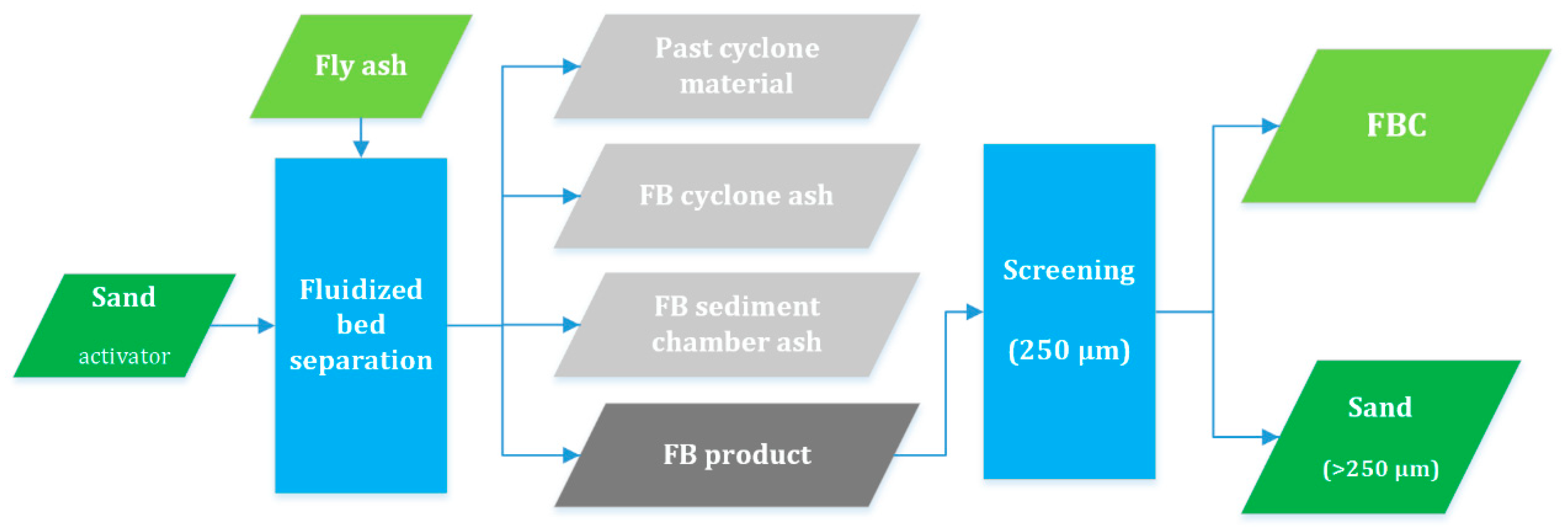
2.1. Fluidised Bed Separation
The main goal of this stage was to isolate the finest fly ash particles to minimise the mass of the material being processed in subsequent stages. A laboratory fluidised-bed reactor with a quartz tube measuring 500 mm in length and 100 mm in diameter was used. The reactor was supplied with 250 g of quartz sand with particle sizes of 300–385 µm. The sand acted as a fluidised bed before adding the fly ash. Afterwards, the sand particles facilitated the separation of the smallest particles by colliding with the fly ash agglomerates. The mutual collisions between the large sand particles and the agglomerate ash particles impaired the weak intermolecular interactions. Thus, the sand acted primarily as a mechanical activator in the FB separation process. The fluidisation was maintained with an airflow of 1.5 dm
3/s at ambient temperature and atmospheric pressure. The fly ash was gradually added at suitable time intervals in ten doses of 100 g each. Simultaneously, the pressure loss was measured using the MPX 2010 DP differential pressure sensor to ensure fine fraction separation. The fly ash particles that were evacuated with air out of the reactor, were collected in the sediment chamber and the cyclone (
Figure 1). All the products from the FB separation were collected and the sand was subsequently removed by sieving it through a 250 µm mesh sieve. The material used in the next separation step was a fraction below 250 µm that was designated as a fluidised bed concentrate (FBC).
2.2. Screening of the Fluidised Bed Concentrate
The sieving analysis of the FBCs was conducted using a set of sieves of mesh sizes: 71, 100, 125, 160 and 200 µm. Two parallel measurements were carried out, these used about 100 g of the material and rubber elements to prevent agglomeration. The aim of dividing the material into grain fractions before the pneumatic separation was the homogenisation of the material to apply distinct conditions for each narrow grain fraction. As a result, the FBCs were divided into three grain fractions (A, B, C). These were subsequently subjected to pneumatic separation. The sieving analysis and further screening were performed in the dry form to eliminate the interaction of the fly ash with water.
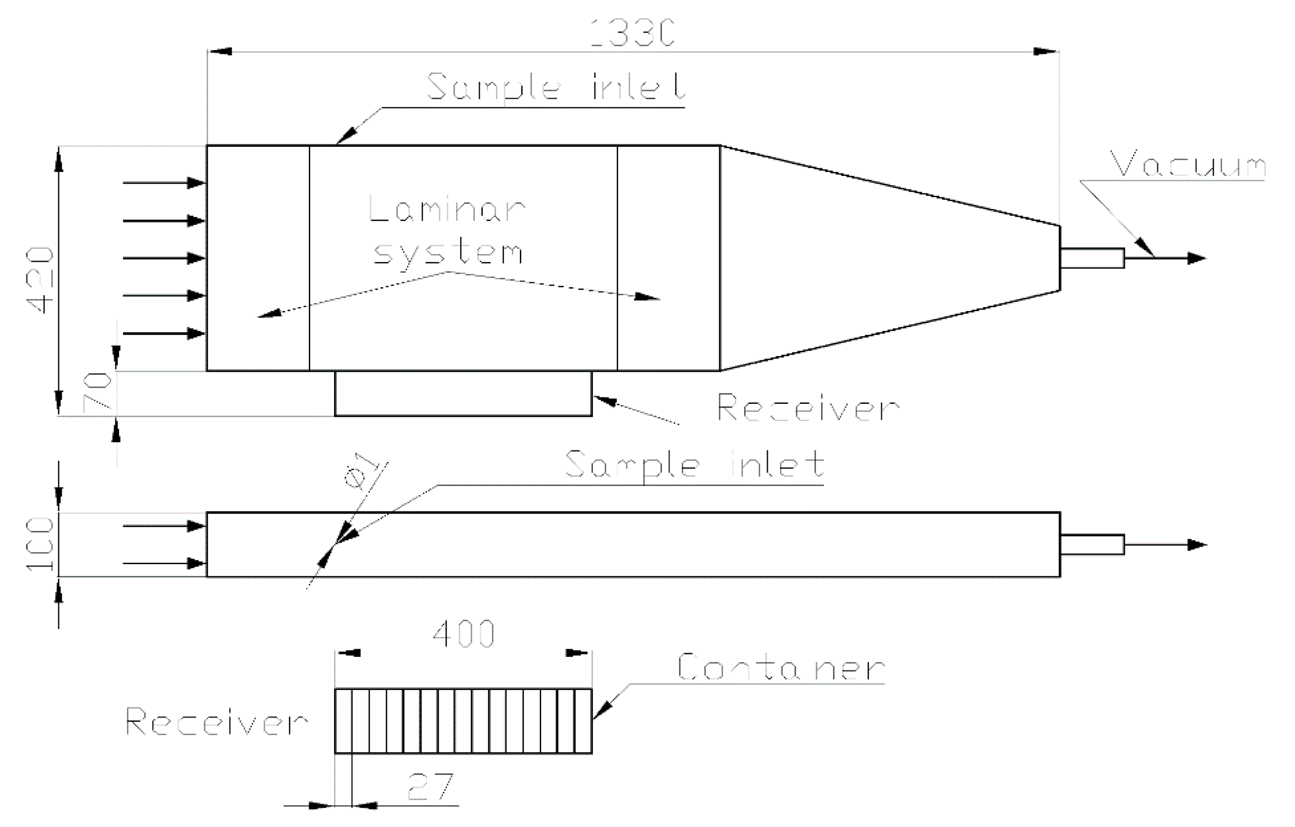
2.3. Pneumatic Separation
The pneumatic separation was conducted in a specially designed device (
Figure 2). The dimensions of the free-fall air chamber were 400 × 100 × 350 mm (length x width x height). The device enables partitioning of the feed into fifteen fractions, which further improves the selectivity of the microsphere recovery. The airflow in the air chamber of the separator was forced by a vacuum controlled by the TSI 40241 mass flowmeter. During the experiment, the outer air flow was monitored by the Lutron AM-4204 hot-wire anemometer. To ensure uniform flow throughout the entire chamber, a laminar system was adopted at both the entrance and the exit of the separating chamber. The FBCs were dosed into the chamber using the plate feeder at a dosing rate of 2, 6 and 3 g/min for the FA
1, FA
2 and FA
3, respectively. Different flow rates were applied to evaluate its influence on the separation efficiency. The fly ashes FA
1 and FA
2 were similar in terms of granulation, hence a triple increase in feed rate would substantially increase the overall yield from the apparatus volume. The air flow rates were approximately 140 dm
3/min, 200 dm
3/min and 300 dm
3/min for the fine (C), medium-grained (B) and coarse fractions (A), respectively. Its values were adjusted for each granular fraction in the manner that no material was located neither before nor past the receiver.
2.4. Microsphere Content Determination
The raw microspheres (part of the fly ash floating on the surface of the water) contain both the microspheres and the unburnt coal (char) particles. To separate these particles, the calcination process was performed in the muffle furnace at 600 °C for 2 h. Afterwards, the MS content in the sample was measured by the sink–float method followed by filtration and drying at 105 °C for 12 h. Analyses were conducted for materials from the sediment chamber and the cyclone as well as for fractions after pneumatic separation. The receiver was divided into fifteen containers. However, the experiments showed that fractions accumulate in a non-uniform manner in the receiver and some fractions weighed less than 1 g. Therefore, to eliminate analytical errors the product of separation was divided into four final parts (I-IV). The combination criteria were the minimum mass of a part (2 g) and maintaining the decreasing tendency of the mass of the following parts.
3. Results and Discussion
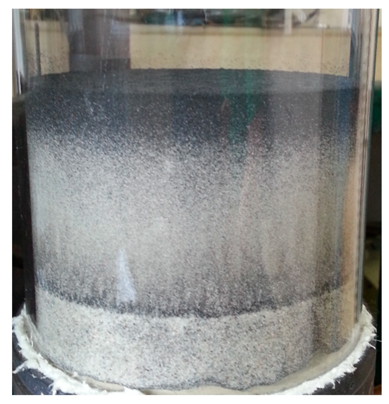
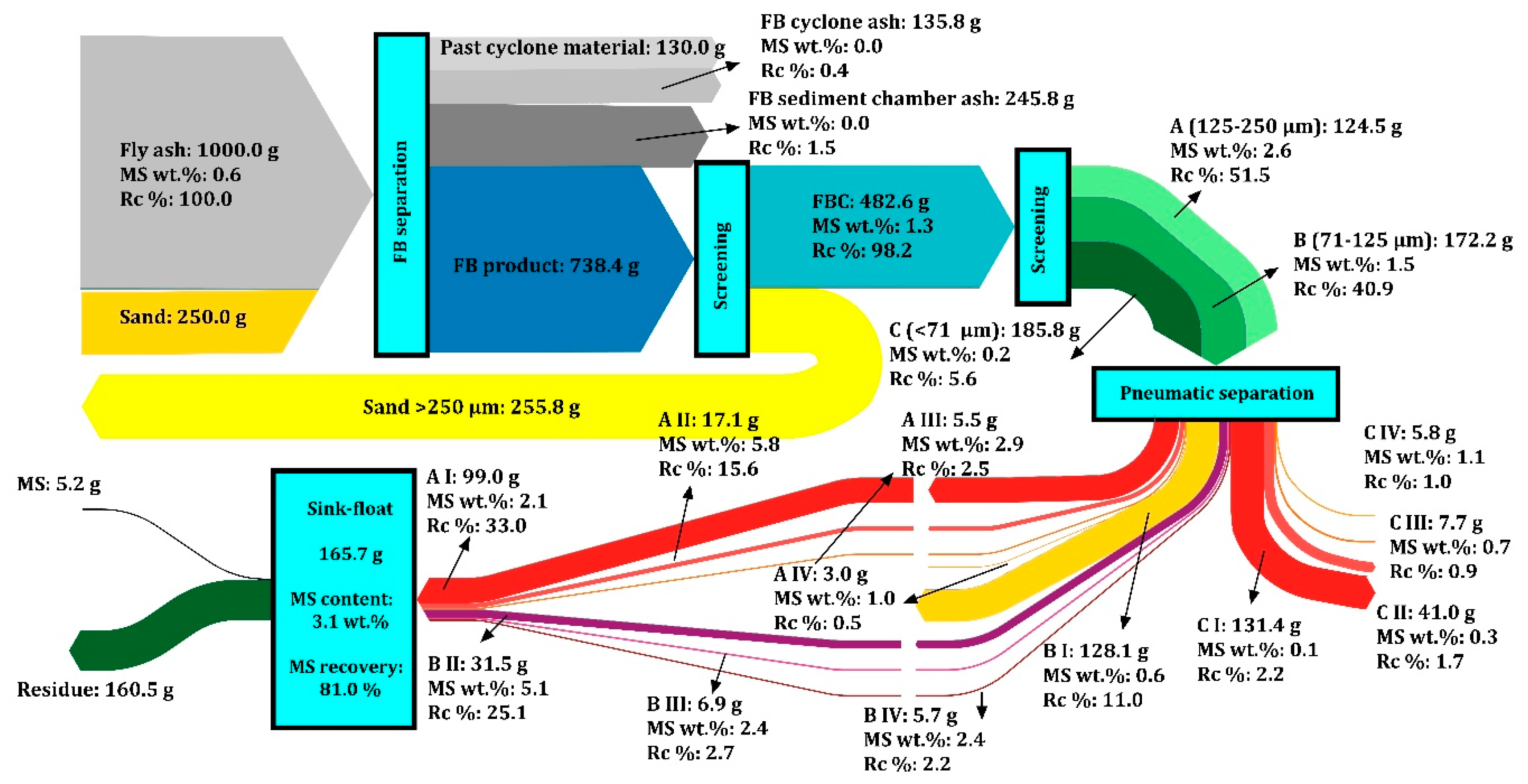
Figure 3 presents the results of the first stage of MS recovery using the fluidised bed reactor. It is clearly shown that the bed, during the process, underwent segregation into characteristic layers: the bottom layer included mostly sand particles, the middle layer consisted of coarse fly ash particles and the upper layer contained in the majority char particles. Hence, there are also alternative ways of retrieving the products from the reactor e.g. layer by layer or continuous separation. Fractions obtained in this manner do not need to be subjected to laborious division into grain fractions, directly isolating the activator from the remaining products.
The mass balance of the process (
Table 1) indicates a significant reduction in the fly ash mass during the FB separation because the FBC represents 45–48 wt.% of the initial fly ash. Therefore, the need for further physical processing is reduced by more than half. Fly ashes from the first hopper (FA
1 and FA
2) possess a similar FBC share, while the finer FA
3 yielded a lower share of the coarse fraction. The majority of the fine fly ash was collected in the sediment chamber and the cyclone. The material that was identified as ‘past cyclone material’ was the finest particles not captured by the cyclone and the residue deposited on the apparatus walls. This was specific to the laboratory set up and did not influence the experiment results. All three types of fine fractions, in summary, shared 51–54 wt.% of the initial fly ash and after this stage of the recovery process could be collectively or individually directed to specific applications. Furthermore, all types of fine fly ash fractions could be treated as valuable material with the low value of fineness (category S according to EN 450-1). Fine fly ash particles proved their superiority in terms of improving the compressive strength of cementitious composites [
38]. Thus, the retrieved fine fraction could be used to produce high-strength concretes.
Based on the FBCs sieve analysis results, two sieves were selected with 71 µm and 125 µm mesh sizes to obtain three fractions with a similar mass share from each concentrate (
Table 2). These fractions were: A (125–250 µm), B (71–125 µm), C (<71 µm). FBC
1 and FBC
2 had similar granulation and both were coarser than FBC
3, which consisted of around 48 wt.% of particles below 71 µm.
The obtained nine materials were subjected to pneumatic separation and were afterwards combined to form four final parts (I–IV). These parts subsequently underwent wet processing to acquire microspheres. The results of the MS content determination in the materials are presented in
Table 3,
Table 4 and
Table 5.
Fluidised bed separation led to a slight concentration of aluminosilicate microspheres. FBCs contained 1.3 wt.%, 1.0 wt.% and 0.8 wt.% of cenospheres with 0.5 wt.%, 0.6 wt.% and 0.3 wt.% of floating unburnt carbon for FBC1, FBC2 and FBC3, respectively. Cenospheres were located mainly in the coarse fractions (A), which contained 53%, 60% and 44% of total cenospheres amount in FA1, FA2 and FA3, respectively. Fine fractions (C) exhibited only about 6% share of total cenospheres amount in FA1 and FA2 and 10% in FA3. This means that simple screening on 71 sieves would provide substantial mass reduction with an acceptable lowering of cenospheres recovery. Nevertheless, the process of pneumatic classification could be an advantageous microsphere concentration method. It facilitates selective fraction collection through the implementation of the receiver consisting of several independent containers.
The raw microspheres obtained from all parts of the FBCs contained a considerable proportion of floating unburnt coal particles (up to 84 wt.%). These were mostly located in parts A, and to a lesser extent, in B. Simultaneously, parts A of FBCs were rich in MS, while parts C contained only up to around 1 wt.% MS. Parts A II and B II of FBC1 were the most abundant in MS with contents of 5.83 wt.% and 5.08 wt.%, respectively. In general, cenospheres and floating unburnt carbon contents were positively correlated, which means that its apparent densities are similar. Separation of these materials is challenging, but the thermal method (calcination) was successfully applied to burnout residual carbon.
The by-products of the FB separation—the sediment chamber ash and the cyclone ash—both contained less than 0.1 wt.% of the MS content in the FA. This means that as high as 98% MS recovery was achieved during the FB process. The process of FB separation using a fluidised bed with a mechanical activator significantly reduces the amount of material subjected to further separation with minimal and negligible microsphere fraction loss.
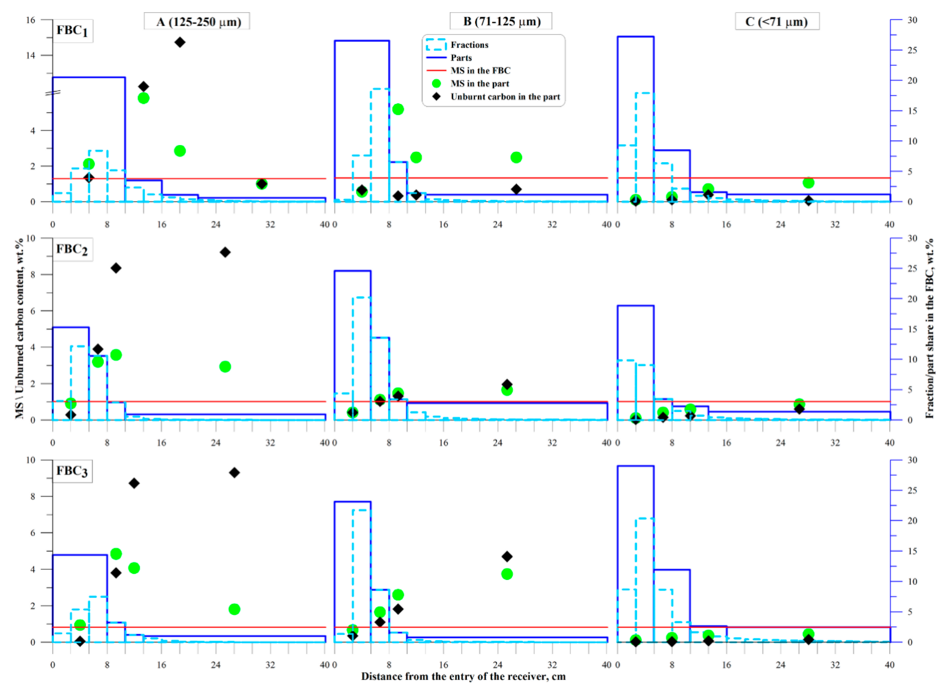
Newton’s efficiency (Equation (4)) had a positive value in reference to selected products of pneumatic separation, showing a MS content greater than that found in the FBCs (
Table 3,
Table 4 and
Table 5). It is clearly shown in
Figure 4, where only some FBCs parts have a MS content (green dots) higher than in the initial FBCs (red line). Grain fractions of FBC
2 and FBC
3 had similar distributions of floating unburnt carbon and MS: fractions A had the maximum MS contents in fractions located around 8–10 cm from the entry of the receiver, while the highest char contents were obtained for the last (IV) parts. In fractions B and C, contents of MS and char were correlated and similar in value. FBC
1 is characterized by different distributions of unburnt carbon and MS (except for the fraction C). The reason for that were higher MS content, lower char content and different partitions of the fractions into final parts in comparison to the FBC
2 and FBC
3.
Figure 4 also provides information about the mass share of fractions collected in the receiver and the way of grouping them into parts. Pneumatic separation of FBC fractions was performed using a feed rate of 2 g/min for FBB
1 and 6 g/min for FBC
2. The increase in feed rate for FBC
2 fractions led to an unfavourable outcome. The first part in coarse fraction (A I) was characterized by the negative value of Newton’s efficiency with relatively high (14%) cenosphere recovery (
Table 4). Thus, rejecting of this fraction from further processing led to a significant reduction in the total recovery. Similar issues were observed for the first part of medium grain fraction (B I) for all FBCs. The explanation of these outcomes could be a high share of collected material in one or two containers of the receiver, rather than its broad distribution like for fraction A of FBC
1. This is one of the main drawbacks of using the pneumatic separator, which could probably be limited by the increase in air flow rate and allowing the evacuation of some of the material out of the apparatus. In this way, material distribution would be broader and at the same time it would be possible to enhance the overall yield by an increase in feed rate. In such a solution, part of the material would be located outside of the receiver and it would cause losses of about 5% of cenospheres, which is acceptable.
4. Conclusions
The utilization level of fly ash in most countries is low, thus there is a need for its further reprocessing. Fly ash beneficiation is in agreement with the practice of sustainable waste management and leads to the increase in the market value of this industrial waste. The proposed solution allows increasing the economic efficiency of energy generation from coal as well as significantly reducing its impact on the environment.
The dry method of the multistage separation of fly ash enables the recovery of materials that have distinct properties. These materials are fine fly ash particles of different grades of fineness, and the microsphere concentrate. The final cenosphere concentrate can be subjected to further separation or it can also become a source of aluminosilicate microspheres by using the wet method. The residue generated after sink–float is coarse and can be directly added to concrete materials as an aggregate replacement. Furthermore, improved fine S-type fly ash in its dry state can be a desirable addition to high-strength concretes.
The process of fluidised bed separation with use of a mechanical activator proved to be extremely effective in the isolation of ultrafine particles and it could be potentially utilized in the other areas where agglomeration of cohesive particles is an issue. More than 50% of the fly ash was elutriated from the bed and the resulting coarse fraction still contained more than 97% of the total cenosphere amount. Further screening steps and pneumatic separation led to as high as 70–80% recovery ratio of cenospheres with over 50% Newton’s efficiency. A novel arrangement of the gravitational-crossflow zone classifier was designed. Such a solution provides opportunities for the flexible grouping of collected fractions. There is no need for modifications to the construction of the designed device dependently of the characteristics of the material. Unlike the solutions known from the literature, the pneumatic separator presented in the work is simple in construction. There are no rotating parts in this device and no additional power supply is required. This reduces the investment and operating costs of separation, increasing its economic efficiency. The constructed pneumatic separator proved its performance, however some additional validation and optimization is required to improve separation selectivity.


