Abstract
Experiments were carried out to investigate the pressure drop and heat transfer behaviors of a microchannel condenser. The effects of gravity on the condensation of steam in the microchannels were investigated for both horizontal and vertical cases. For the experimental results, the pressure drop of vertical microchannels in the condenser is lower than for horizontal microchannels. In the case of the horizontal microchannel, as the mass flow rate of steam increases from 0.01 g·s−1 to 0.06 g·s−1, the pressure drop increases from 1.5 kPa to 50 kPa, respectively. While the mass flow rate of steam in the vertical microchannel case increases from 0.01 g·s−1 to 0.06 g·s−1, the pressure drop increases from 2.0 kPa to 44 kPa, respectively. This clearly indicates that the gravitational acceleration affects the pressure drop. The pressure drop of the vertical microchannel is lower than that obtained from the horizontal microchannel. In addition, the capacity of the condenser is the same in both cases. This leads to the performance index obtained from the vertical microchannel condenser being higher than that obtained from the horizontal microchannel condenser. These results are important contributions to the research on the condensation of steam in microchannels.
1. Introduction
In recent years, microchannel heat exchanger technologies have received much attention due to their high heat transfer efficiency. The main advantages of microscale devices are their higher heat transfer coefficients and smaller characteristic dimensions. The growing interest in microchannel heat exchangers and their applications has motivated many researchers to investigate flow phenomena in microchannels. Previous studies focused on the characteristics of heat transfer and fluid flow at the microscale level in order to improve the design and optimize the performance of microchannel heat exchangers. In addition to this, many studies on convective heat transfer and the pressure drop in internal microtubes and microchannels have been extensively implemented in the past decade.
Tuckerman et al. [1] investigated the heat transfer of water flowing under laminar conditions in silicon microchannels. A heat flux value of 790 W·cm−2 was obtained while the chip temperature was maintained below 110 °C. Fayyadh et al. [2] implemented experiments to investigate the flow boiling heat transfer of R134a in a multi microchannel heat exchanger. The results showed that the heat transfer coefficient increased with heat flux and there was no mass flux effect. Three micro-condensers were studied: the microchannel condenser, parallel phase separation condenser, and conical phase separation condenser.
Micro-condensers had a condensation surface of 25.0 mm × 3.0 mm; the etched depth was 75 μm. Water vapor was used as the working fluid. The results indicated that the conical phase separation condenser increased the heat transfer coefficients by 74% maximally, while the pressure drops decreased. This indicates that the conical phase separation condenser obtained the best performance among the three condensers [3]. An experimental study on the condensation pressure drop in R14 in a horizontal tube with an inner diameter of 4 mm was implemented. An enhanced pressure drop correlation and heat transfer was indicated and predicted the R14 experimental data well, with a mean absolute relative deviation of 12.18% and 6.26% [4,5].
Dang and Teng [6] conducted an experimental study on the influences of configurations on the performance of microchannel heat exchangers. In this study, the highest performance index (expressed as the ratio of the heat transfer rate to the pressure drop) of 21.67 W/kPa was achieved for the heat exchanger with the lowest thickness. Dang et al. [7] studied simulations and experiments for a microchannel counter-flow heat exchanger. The paper presented an experimental study of the effects of gravity on heat transfer and the pressure drop behaviors of the microchannel heat exchanger. However, the results in [7] were determined for single-phase fluids only. The pressure drop in CO2 was investigated in adiabatic conditions; it increased with the increase in mass flux and vapor quality, and it reduced with the increase in saturation temperature [8].
Dang et al. [9] studied the subcooling process of a transcritical CO2 air conditioning cycle working with a microchannel evaporator. In this study, the main thermodynamic points of the cycle achieve a high COP (coefficient of performance) with a gas cooler pressure of 75 bar. However, this study did not mention the gravitational force in microchannels. Kim et al. [10,11] investigated the condensation of FC-72 along parallel, square microchannels with a hydraulic diameter of 1 mm and a length of 29.9 cm. The results showed that the homogenous flow model produced far more accurate predictions of pressure drop than the separated flow models.
Liu et al. [12] reported an experiment on heat transfer and pressure drop during the condensation of R152a in circular and square microchannels. The results indicated that the heat transfer coefficients and pressure drop both increased with increasing mass flux and vapor mass quality and decreased with increasing saturation temperature. Sahara et al. [13,14] implemented several simulations to investigate the effects of hydraulic diameter, single phase flow, and conjugate heat transfer in copper rectangular microchannels. The results showed that the effect of the aspect ratio and hydraulic diameter on the dimensionless hydrodynamic entry length was not significant. Additionally, the aspect ratio had no effect on the heat transfer coefficient, while the dimensionless Nusselt number increased with the increasing hydraulic diameter.
The enhancement of the heat transfer process in laminar and turbulent flows was experimentally studied by using water as the working fluid in a narrow rectangular channel, with a gap of 3 mm, hydraulic diameter of 5.58 mm, and length to diameter ratio (L/Dh) of 80.65 [15]. The results showed that the laminar to turbulent transition occurred at an earlier stage, with the help of longitudinal vortices.
Cavallini et al. [16] showed a pressure drop during adiabatic flow in R134a, R236ea, and R410A at 40 °C inside a multiport minichannel which had square cross-section ports with a hydraulic diameter of 1.4 mm and a length of 1.13 m and with mass velocities ranging from 200 kg·m−2·s−1 to 1400 kg·m−2·s−1. Liu and Li [17] implemented an experimental study on pressure drop in R32, R152a, and R22 during condensation in two square (Dh = 0.952 and 1.304 mm) and one circular (Dh = 1.152 mm) horizontal minichannels. The results showed that the pressure drops increased with increasing mass flux and vapor quality and decreasing saturation temperature and channel diameter.
The heat transfer during the condensation of R134a inside eight parallel microchannels was investigated by Goss and Bassoc [18]. The results demonstrated that there is no clear influence of the heat flux rejected on the heat transfer coefficient for the range tested. Additionally, the heat transfer coefficient increased with a rise in the velocity.
Mala and Li [19] investigated the pressure gradients of water flowing through stainless steel and fused silica micro tubes. The tubes had inner diameters ranging from 50 μm to 254 μm. The results indicated that the pressure gradients of smaller micro tubes, with inner diameters below 150 μm, were up to 35% higher than those predicted by the conventional theory.
The pressure drop of water flowing through trapezoidal silicon microchannels with hydraulic diameters ranging from 51 μm to 169 μm was investigated by Qu [20]. The results showed that the friction factors in the trapezoidal channels were higher than the conventional theory. Sakamatapan et al. [21,22] studied the pressure drop characteristics of R134a during condensation in two multiport minichannels. The results indicated that the friction pressure gradients increased with the vapor quality and mass flux but reduced with increasing saturation temperature and channel size.
Viscito et al. [23] presented a global analysis of the effect of the channel orientation on the two-phase heat transfer coefficient. The study was implemented by collecting 5408 data points from independently published works, which included flow boiling, flow condensation, and heated gas–liquid flows at various orientations with respect to the gravity force. The results against existing prediction methods for two-phase heat transfer, including the tube orientation effect, have shown very poor agreement, and no general tool is available in the literature to determine whether the effect of gravity is negligible or of major importance for specific applications. Therefore, they suggested a new prediction tool. This tool can be employed in the design process of condensing and evaporating units, since it is able to establish whether the heat transfer coefficient might be effected by the channel orientation or, instead, a typical correlation for non-inclined tubes can be used.
Hrnjak and Litch [24] implemented a study of two aluminum condensers: a microchannel condenser (with a parallel tube arrangement between headers and microchannel tubes, with a hydraulic diameter Dh = 0.7 mm) and another one (with a single serpentine macrochannel tube with a hydraulic diameter Dh = 4.06 mm). The ratio of the amount of working fluids charged to the capacity of the microchannel condenser was around 76% less than for the serpentine condenser.
Park and Hrnjak [25] studied two R410A residential air-conditioning systems, one with a microchannel condenser and the other with a round-tube condenser. The cooling capacity and the coefficient of performance (COP) of the system with the microchannel condenser were 3.4% and 13.1% higher, respectively.
Hu and Chao [26] investigated five condensation flow patterns for water in a silicon micro condenser. For a hydraulic diameter of 73 μm and a range of mass fluxes of steam of 5 to 45 kg/(m2s), the heat transfer coefficients obtained were from 220 to 2400 W/(m2·K), and the corresponding pressure drops were from 100 to 750 kPa/m.
Alm et al. [27] manufactured ceramic microstructure devices in the form of counter-flow and cross-flow microchannel heat exchangers, which are used in thermal and chemical process engineering. The peak experimental heat transfer coefficient for the cross-flow heat exchanger was observed to reach 22 kW/(m2·K).
From the literature reviewed above, studies of the influence of gravitational force on condensation, as well as two-phase fluid in microchannels, have not been well demonstrated, especially in experiments. Therefore, it is necessary to experimentally study the influence of gravitational force on the heat transfer and pressure drop characteristics for the condensation in microchannels. In the following sections, a microchannel condenser will be tested for the horizontal and vertical cases, varying the mass flow rates of the steam, the condensed water, and the temperature difference.
2. Methodology
2.1. Mathematical Equations
The governing equations used to calculate and design the microchannel condenser are as follows [28,29]:
The pressure drop was presented by:
Δp = p1 − p2
The temperature difference of cooling water was calculated by:
ΔT = T4 − T3
The capacity of the condenser was determined as:
where p1 is the pressure of steam at the inlet (Pa), p2 is the pressure of condensed water at the outlet (Pa), m is the mass flow rate of steam (g·s−1), h is the enthalpy (kJ·kg−1) (the subscript IS stands for inlet steam and OW stands for outlet condensed water), r is the latent heat of condensation (kJ·kg−1), Cp is the specific heat capacity (kJ·kg−1·K−1), T1 and T2 are the temperatures of steam and condensed water (K), and T3 and T4 are the inlet temperature and outlet temperature of cooling water (K).
Qs = m·(hIS − hOW) = m·(r + Cp1·T1 − Cp2·T2)
The performance index was solved with:
The heat transfer equation was used as:
with
and
Qw = U·F·ΔTLM
The heat transfer efficiency of the condenser was determined by:
where the performance index is the ratio of the capacity condenser and the pressure drop (W·Pa−1), Qs is the capacity of the condenser (W), Qw is the heat transfer rate (W), U is the overall heat transfer coefficient (W·m−2·K−1), F is the heat transfer surface of the model (m2), and ΔTLM is the logarithmic mean temperature difference (K).
2.2. Microchannel Heat Exchanger Fabrication
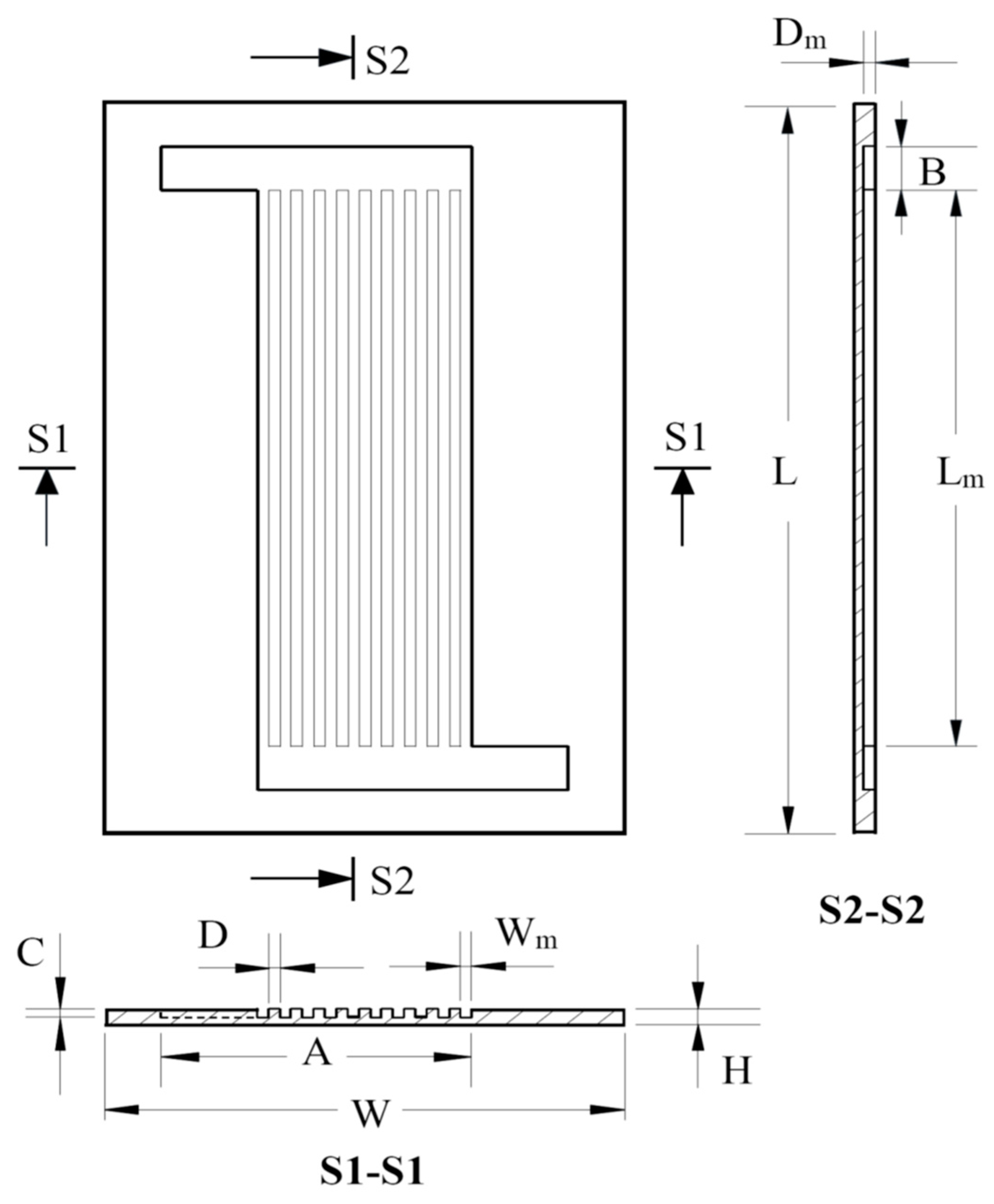
In this work, a microchannel condenser was designed and tested. Figure 1 shows the dimensions of the test sections. The fabricated material of heat exchangers was aluminum, which was designed as a substrate with a thermal conductivity of 237 W·m−1·K−1. The substrate thickness of the microchannel heat exchanger was 700 μm, and the channel depth for the cooling waterside was 500 μm (corresponding with the channel hydraulic diameter of 500 μm).
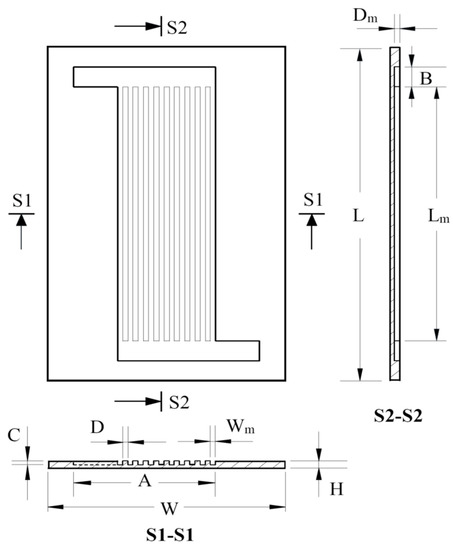
Figure 1.
The design of the microchannel condenser.
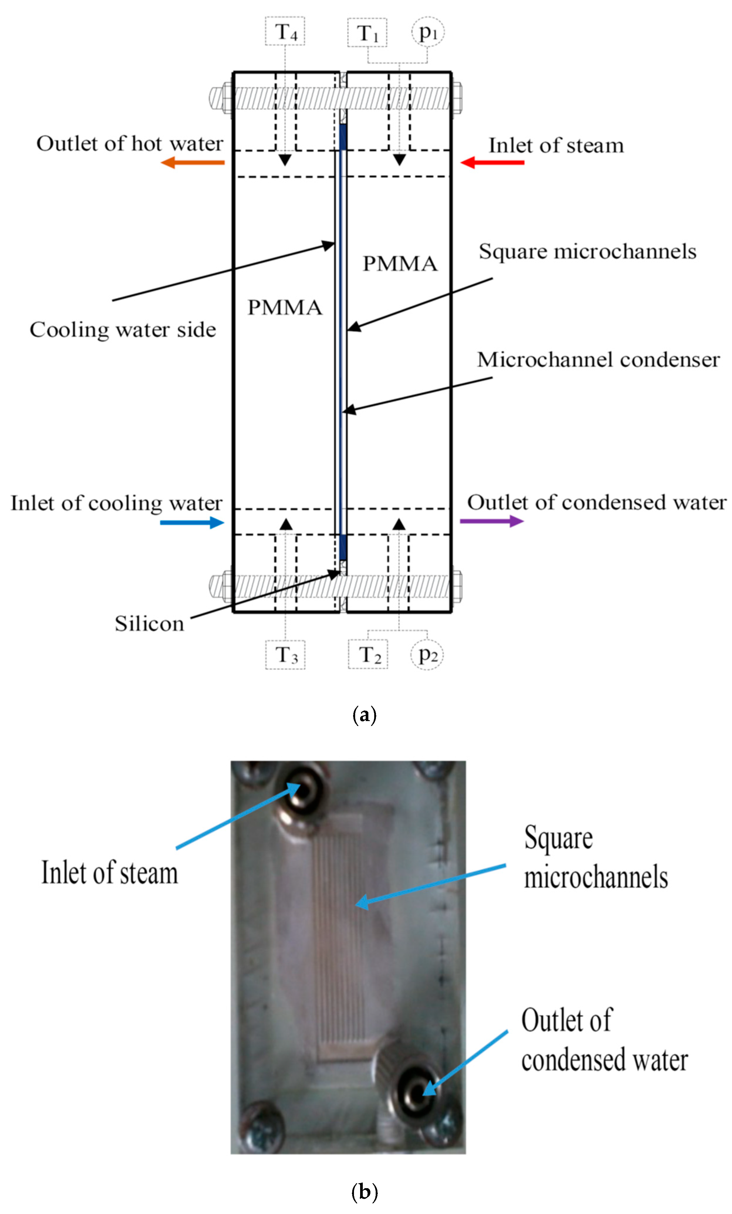
The geometric parameters of the model are listed in Table 1. A manifold is designed to connect with all channels for each inlet and outlet of vapor and cooling water, respectively. The shape of the manifolds is rectangular, with a width of 2.5 mm and a depth of 500 μm. Figure 2 shows a schematic of the microchannel heat exchanger assembly. Each inlet or outlet of the heat exchanger has a cross-sectional area of 1.25 mm2. Four sides of the model are thermally insulated by glass wool with a thickness of 10 mm. Two layers of polymethyl methacrylate are bonded on the top and bottom sides of the substrate to seal the microchannels, with a thickness of 10 mm (as indicated in Figure 2).

Table 1.
The geometric parameters.
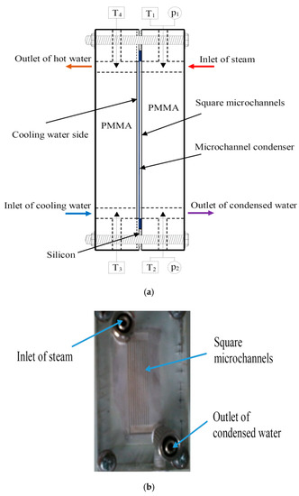
Figure 2.
The schematic of the microchannel heat exchanger assembly, side-view. Polymethyl methacrylate (PMMA). (a) Parts of the condenser; (b) a photo of the condenser (as fabricated).
2.3. Experimental Setup
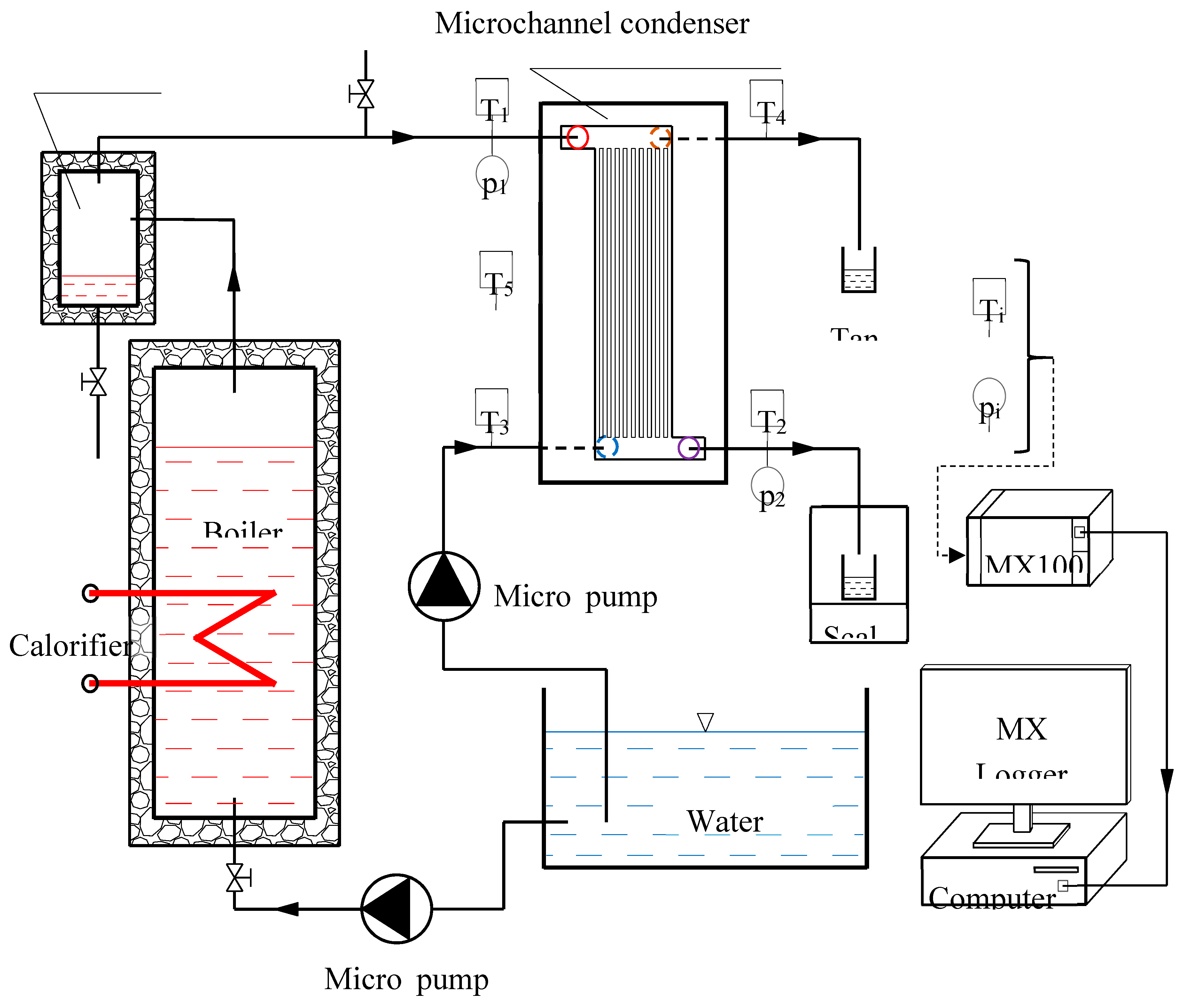
As shown in Figure 3, the testing system includes six major components, including the microchannel condenser, two micro pumps, the steam boiler, steam accumulator, and water tank. The produced vapor in the boiler moves to the accumulator and then passes through the micro condenser, where it is condensed by the cooling water. The microchannel condenser was designed and tested in two cases: horizontal and vertical assembly. A temperature sensor was set to record the temperature values at each inlet or outlet. Four T-type thermocouples (PT-100, Omega, Taiwan) were used to record the inlet and outlet water temperatures. These thermocouples were inserted into the tubes at the inlets and the outlets. The temperature signal was collected using a MX100 data acquisition unit (as shown in Figure 4). The data were eventually transferred to a computer. For pressure measurements, pressure sensors were used to record the pressure parameters at each inlet/outlet. A differential pressure transducer was also used to record the pressure drop for the steam side or the cooling water side. Table 2 shows the accuracies and ranges of the testing apparatuses.
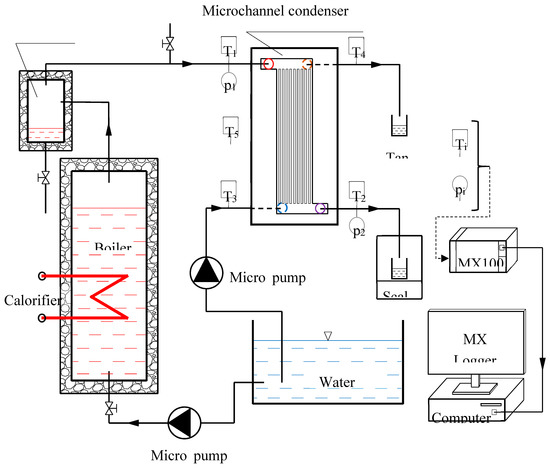
Figure 3.
Schematic illustration of the experimental system.
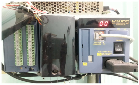
Figure 4.
The MX100 data acquisition unit.
Table 2.
The accuracies and ranges of the testing apparatuses.
3. Results and Discussion
3.1. Effects of the Inlet Steam Flow Rate on the Pressure Drop in a Horizontal Assembly
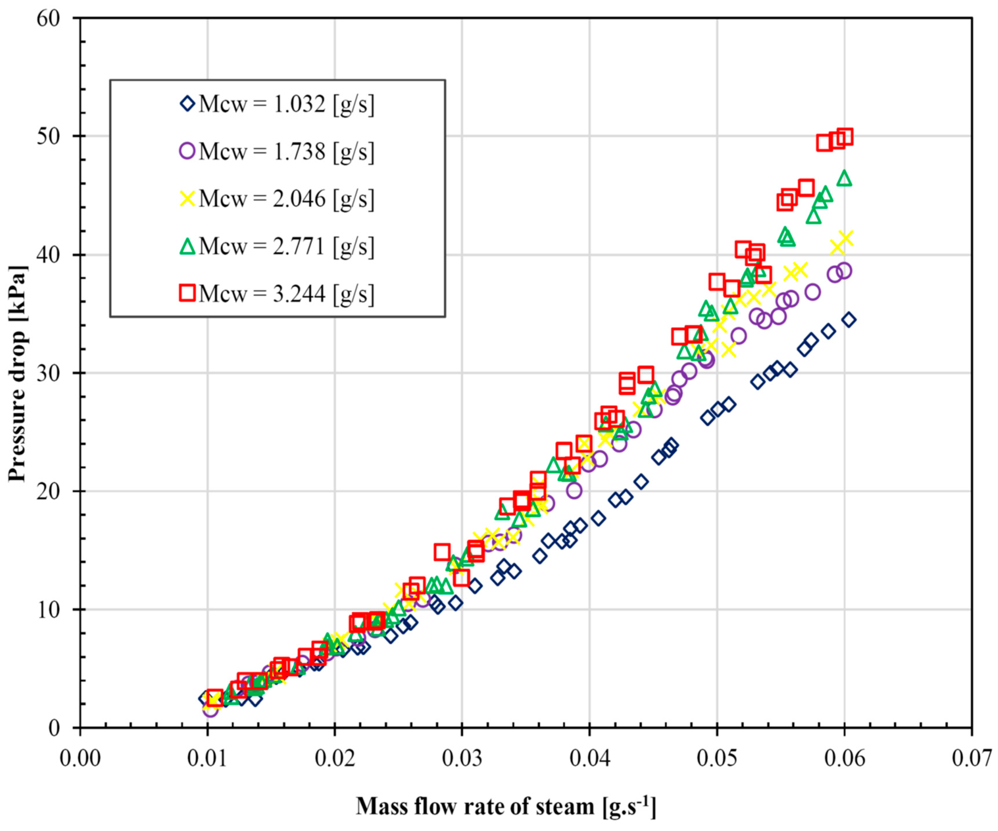
Figure 5 shows the effect of the inlet steam flow rate and the mass flow rate of cooling water on the pressure drop of the microchannel condenser in a horizontal assembly. The experiment investigated the flow rate of steam from 0.01 g·s−1 to 0.06 g·s−1 with different cooling water flow rates at the inlet (1.032; 1.738; 2.046; 2.771; and 3.224 g·s−1). As shown in Figure 5, the pressure drop is low at the steam mass flow rate of 0.01 g·s−1 with similar cooling water flow rates. The pressure drop increases with an increase in the steam mass flow rate, especially when the steam mass flow is larger than 0.03 g·s−1. In addition, the pressure drop also increases when the mass flow rate of cooling water increases. In this study, the highest pressure drop is 50 kPa, at the highest mass flow rate of cooling water of 3.244 g·s−1. This indicates that the heat exchange process affects the mass flow of condensed water inside.

Figure 5.
The effects of steam and cooling water mass flow rate on a horizontal microchannel.
3.2. Comparison of the Gravity Effect on Mh and Mv
Figure 6 indicates the pressure drop between the inlet and outlet with a mass flow rate of steam from 0.01 g·s−1 to 0.06 g·s−1 in the horizontal (Mh) and vertical (Mv) microchannel cases. As shown in Figure 6, the pressure drop of vertical microchannels is lower than for horizontal microchannels. With the horizontal microchannel condenser, as the mass flow rate of steam increases from 0.01 g·s−1 to 0.06 g·s−1, the pressure drop increases from 1.5 kPa to 50 kPa, respectively. When the mass flow rate of steam in the vertical microchannel condenser increases from 0.01 g·s−1 to 0.06 g·s−1, the pressure drop increases from 2.0 kPa to 44 kPa, respectively.
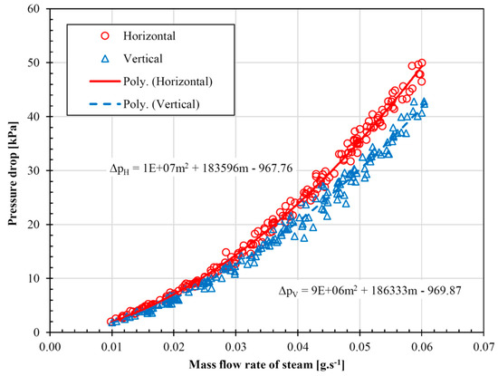
Figure 6.
Comparison of pressure drops in the cases of horizontal and vertical microchannels.
This clearly indicates that the gravitational acceleration affects the pressure drop. This can be explained, in the case of horizontal microchannels, by the fact that the water flows are perpendicular to the gravitational acceleration, whereas they are in the same direction in the case of vertical microchannels, where the state causes the hot water to leave the condenser faster than in a horizontal microchannel. In addition, in the case of a vertical microchannel condenser, the volume of water is lower than the volume of steam compared to the case of a horizontal microchannel condenser. Compared with the results in [7], the dimensions of the microchannel heat exchangers are similar. However, the influence of gravity on the pressure drop in a microchannel heat exchanger is negligibly small for a single-phase fluid [7]. With the two-phase fluid or condensation in microchannels, the pressure drop depends on the gravity. This is an interesting difference between the single-phase fluid and two-phase fluid. The results also show that the condensation of steam in the microchannels should be placed vertically in order to obtain a smaller pressure drop.
3.3. Different Temperatures of Cooling Water in Horizontal and Vertical Microchannels
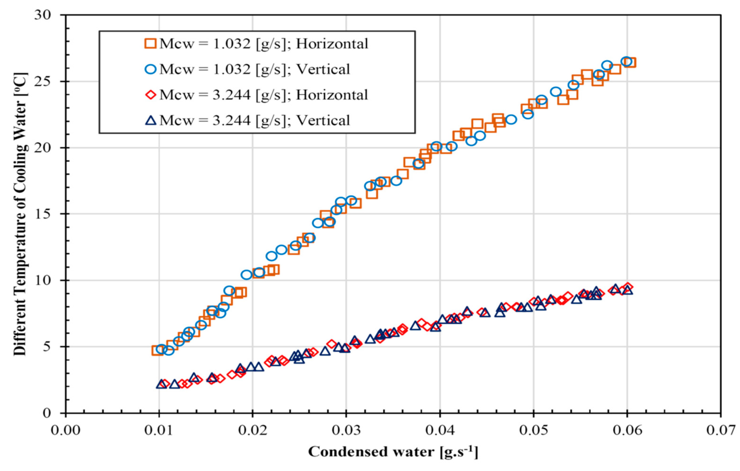
Figure 7 depicts the flow rate of condensed water in horizontal and vertical microchannels with the mass flow rates of the cooling water at 1.032 g·s−1 and 3.244 g·s−1, at different temperatures of the cooling water. As shown in Figure 7, the mass flow rate of condensed water increases from 0.01 g·s−1 to 0.06 g·s−1 in both horizontal and vertical assemblies, with the mass flow rate of cooling water at 1.032 g·s−1 and 3.244 g·s−1. The mass flow rate of condensed water linearly increases for both the horizontal and vertical microchannel condensers. However, the different temperatures with the flow rate of cooling water at 1.032 g·s−1 must be much higher than the different temperatures with the flow rate of cooling water at 3.244 g·s−1 in order to obtain a similar mass flow rate of condensed water.
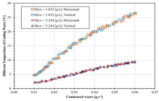
Figure 7.
The effect of different temperatures of cooling water on the condensed water flow rate.
3.4. Effects of the Steam Mass Flow Rate on the Performance Index and Capacity
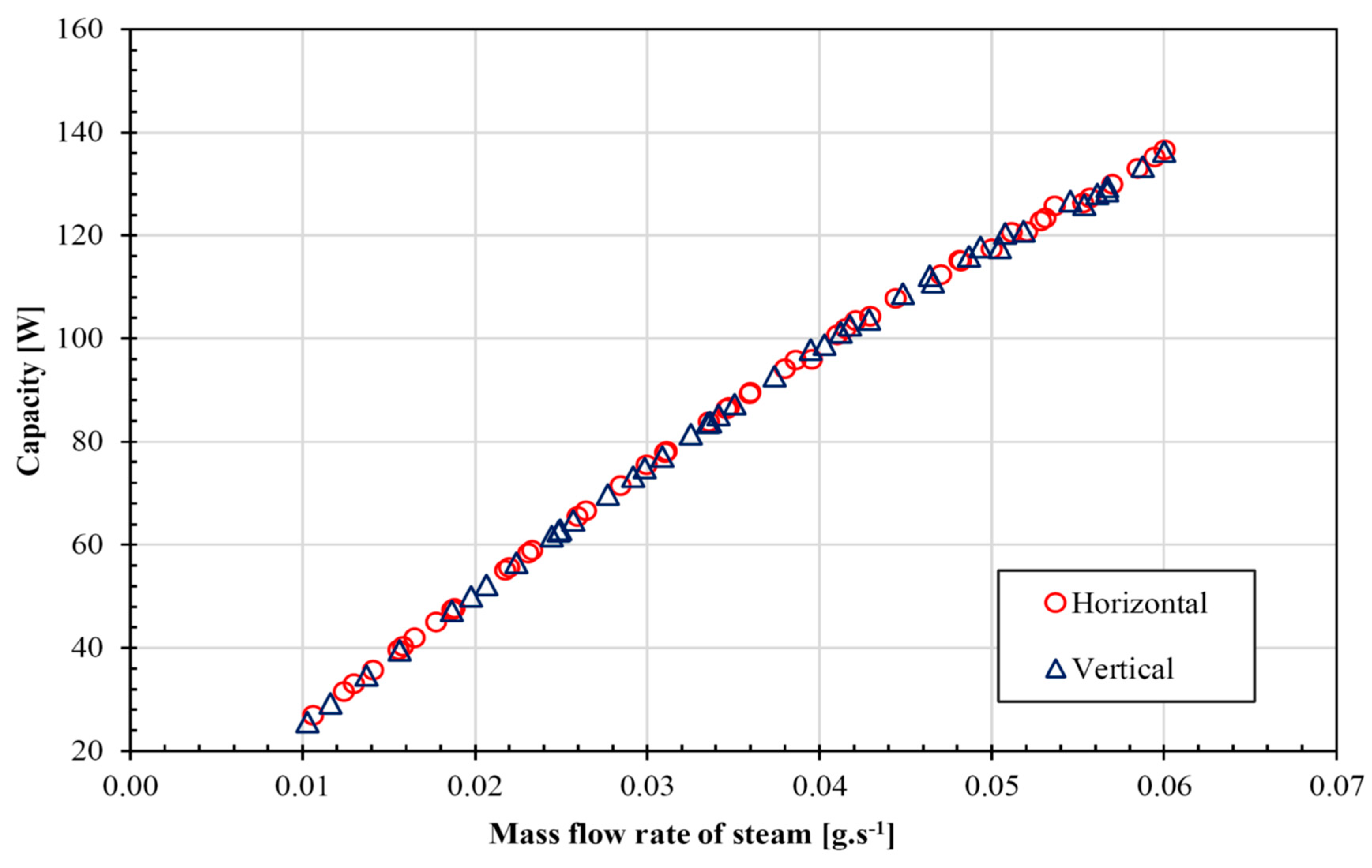
Figure 8 shows the capacity of the microchannel condenser in horizontal and vertical assemblies when increasing the mass flow rate of steam. As shown in Figure 8, as the capacity increases from 20 to 140 W, the mass flow rate of the steam increases from 0.01 g·s−1 to 0.06 g·s−1 in both the horizontal and vertical assemblies. The capacity linearly increases for both cases with the rising of the mass flow rate of steam. The capacity of the condenser is the same for the horizontal and vertical cases; these results are similar with the single-phase fluid, whereby the influence of gravity on the capacity of the microchannel heat exchanger is negligibly small.
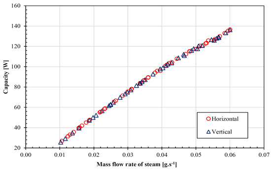
Figure 8.
The effect of the inlet of the steam mass flow rate on the condenser capacity.
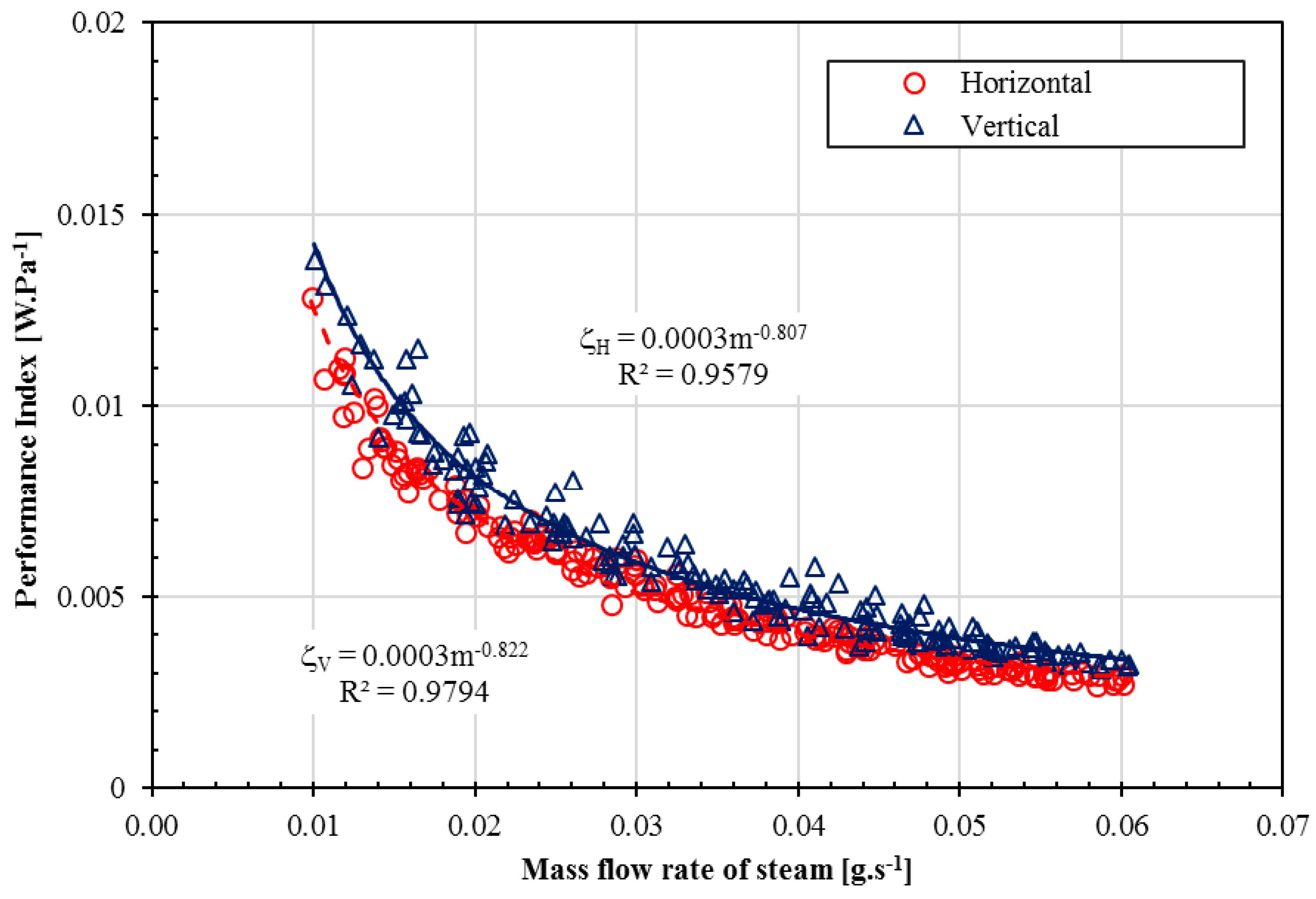
Figure 9 shows the performance index of a microchannel condenser in a horizontal and vertical assembly. Figure 9 indicates that the performance index obtained from the vertical microchannel condenser is higher than for a horizontal microchannel condenser. This indicates that the gravitational acceleration affects the performance index. As shown in Figure 9, the performance index depends on the mass flow rate of the steam: the performance index decreases as the mass flow rate of steam rises. With an increase in the mass flow rate of steam from 0.01 g·s−1 to 0.06 g·s−1, the performance index for the horizontal microchannel case decreases from 0.0141 to 0.0029 W·Pa−1; for the performance index of the vertical case, it decreases from 0.0145 to 0.0025 W·Pa−1.
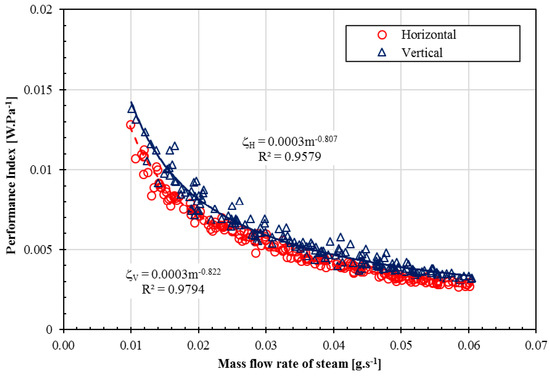
Figure 9.
Comparison of the performance index in the cases of horizontal and vertical microchannels.
3.5. Overall Heat Transfer Coefficient
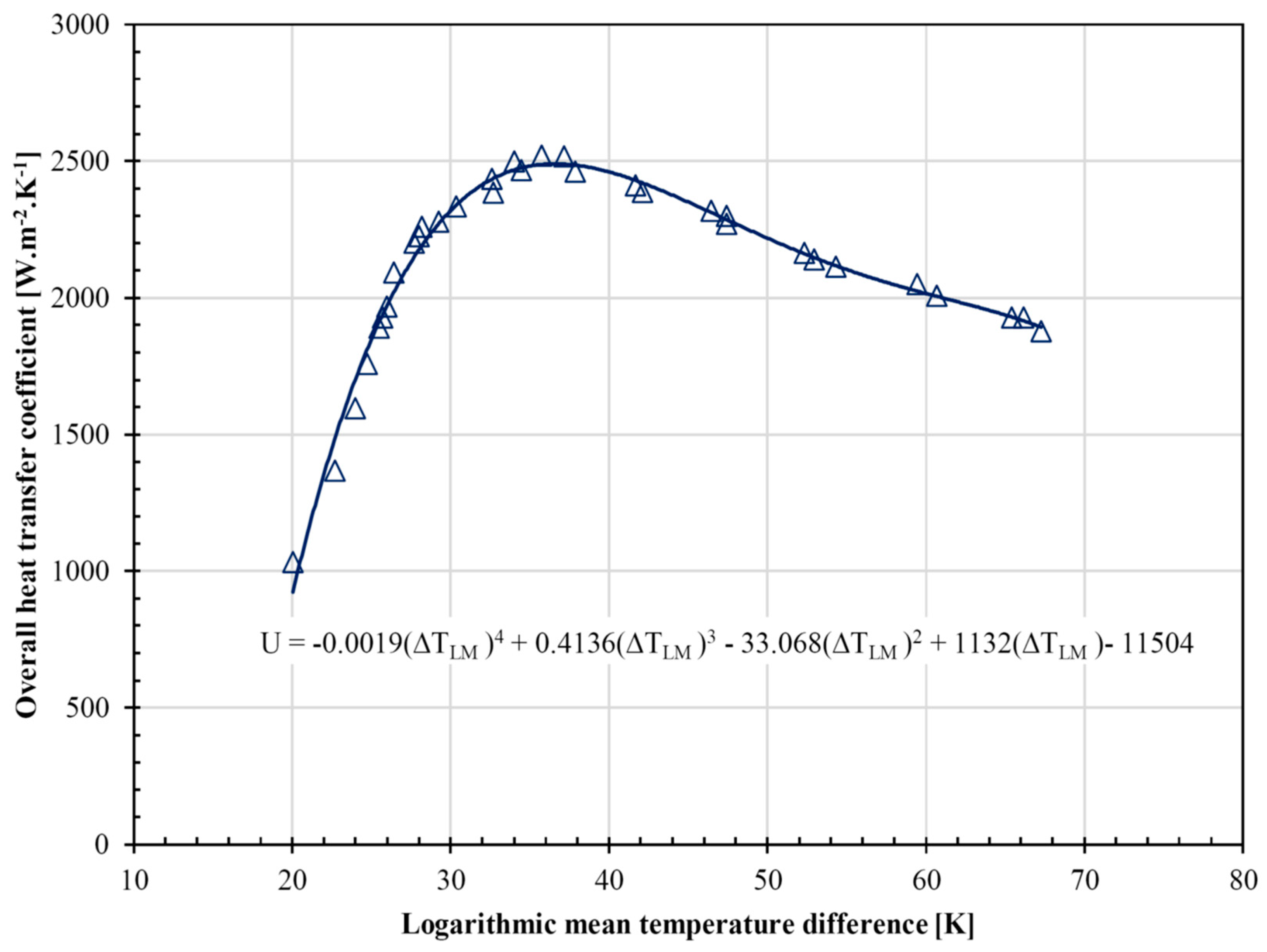
From the experimental data, a relationship between the logarithmic mean temperature difference and the overall heat transfer coefficient was established, as shown in Figure 10. The highest overall heat transfer coefficient (2500 W·m−2·K−1) of the microchannel condenser is obtained at the log mean temperature difference of 35 K. These results are new and very useful for designing microchannel condensers, as well as for microchannel heat exchangers using two-phase fluids.

Figure 10.
Overall heat transfer coefficient in the case of a vertical microchannel.
4. Conclusions
An experimental investigation was implemented in both horizontal and vertical microchannels. The results indicate that the pressure drop in the case of the horizontal microchannel is higher than for the vertical microchannel. This clearly indicates that the pressure drop depends on the gravitational acceleration in the condensation process of steam in the microchannel. This is the difference between the single-phase fluid and the two-phase fluid in microchannel heat exchangers. In addition, the pressure drop increases with an increase in the mass flow rate of steam; however, the pressure drop decreases with a decrease in the mass flow rate of cooling water.
The capacity linearly increases for both horizontal and vertical microchannel cases as the steam mass flow rate rises. However, the capacity of the condenser is the same for both the horizontal and vertical cases. The performance index obtained from the vertical microchannel condenser is higher than for the horizontal microchannel condenser. We conclude that the gravitational acceleration affects the performance index of the condenser. The results also show that the condensation of steam in the microchannels should be placed vertically in order to obtain a smaller pressure drop and a higher performance index.
In addition, we established a relationship between the log mean temperature difference and the overall heat transfer coefficient of the condenser. The highest overall heat transfer coefficient (2500 W·m−2·K−1) of the condenser is obtained at the log mean temperature difference of 35 K. In this work, the study goal was to investigate the total pressure drop and the overall heat transfer coefficient, as well as the performance index, in order to determine the heat transfer characteristics of the microchannel condenser. These results are very useful for designing and fabricating microchannel condensers as well as microchannel heat exchangers using two-phase fluids.
Author Contributions
Conceptualization, methodology, investigation, and data curation, M.D.; writing—original draft preparation, submitting, review and editing, X.N.; supervision, T.D. All authors have read and agreed to the published version of the manuscript.
Funding
This work belongs to the project grant No: T2019-20TĐ. funded by Ho Chi Minh City University of Technology and Education, Vietnam.
Acknowledgments
The authors gratefully thank the Ho Chi Minh City University of Technology and Education for the financial support.
Conflicts of Interest
The authors declare no conflict of interest.
Nomenclsature
| Cp | Specific heat at constant pressure (kJ·kg−1·K−1) |
| F | Heat transfer surface of model (m2) |
| h | Specific enthalpy (kJ·kg−1) |
| M | Mass flow rate (g·s−1) |
| p | Pressure (Pa) |
| Qs | Capacity of condenser (W) |
| Qw | Heat transfer rate (W) |
| T | Temperature (K) |
| U | Overall heat transfer coefficient (W·m−2·K−1) |
| ζ | Performance index (W·Pa−1) |
| η | Heat transfer efficiency of condenser |
| ΔTLM | Logarithmic mean temperature difference (K) |
| Subscripts | |
| IS | inlet steam |
| OW | outlet condensed water |
| H | horizontal |
| V | vertical |
| COP | coefficient of performance |
References
- Tuckerman, D.; Pease, R. High-performance heat sinking for VLSI. IEEE Electron Device Lett. 1981, 5, 126–129. [Google Scholar] [CrossRef]
- Fayyadh, E.M.; Mahmoud, M.M.; Sefiane, K.; Karayiannis, T.G. Flow boiling heat transfer of R134a in multi microchannels. Int. J. Heat Mass Transf. 2017, 110, 422–436. [Google Scholar] [CrossRef]
- Yu, X.J.; Xu, J.L.; Yuan, J.D.; Zhang, W. Microscale phase separation condensers with varied cross sections of each fluid phase: Heat transfer enhancement and pressure drop reduction. Int. J. Heat Mass Transf. 2018, 118, 439–454. [Google Scholar] [CrossRef]
- Song, Q.L.; Chen, G.F.; Guo, H.; Shen, J.; Gong, M.Q. Two-phase flow condensation pressure drop of R14 in a horizontal tube: Experimental investigation and correlation development. Int. J. Heat Mass Transf. 2019, 139, 330–342. [Google Scholar] [CrossRef]
- Song, Q.L.; Chen, G.F.; Xue, H.W.; Zhao, Y.X.; Gong, M.Q. R14 flow condensation heat transfer performance: Measurements and modeling based on two-phase flow patterns. Int. J. Heat Mass Transf. 2019, 136, 298–311. [Google Scholar] [CrossRef]
- Dang, T.T.; Teng, J.T. The effects of configurations on the performance of microchannel counter-flow heat exchangerse: An experimental study. Appl. Therm. Eng. 2011, 31, 3946–3955. [Google Scholar] [CrossRef]
- Dang, T.T.; Teng, J.T.; Chu, J.C. A study on the simulation and experiment of a microchannel counter-flow heat exchanger. Appl. Therm. Eng. 2010, 30, 2163–2172. [Google Scholar] [CrossRef]
- Park, C.Y.; Hrnjak, P. CO2 flow condensation heat transfer and pressure drop in multiport microchannels at low temperatures. Int. J. Refrig. 2009, 32, 1129–1139. [Google Scholar] [CrossRef]
- Dang, T.; Vo, K.; Le, C.; Nguyen, T. An experimental study on subcooling process of a transcritical CO2 air conditioning cycle working with microchannel evaporator. J. Therm. Eng. 2017, 3, 1505–1514. [Google Scholar] [CrossRef]
- Kim, S.M.; Kim, J.; Mudawar, I. Flow condensation in parallel microchannels–Part1: experimental results and assessment of pressure drop correlations. Int. J. Heat Mass Transf. 2012, 55, 971–983. [Google Scholar] [CrossRef]
- Kim, S.M.; Mudawar, I. Universal approach to predicting two-phase frictional pressure drop for adiabatic and condensing mini/microchannel flows. Int. J. Heat Mass Transf. 2012, 55, 3246–3261. [Google Scholar] [CrossRef]
- Liu, N.; Li, J.M.; Sun, J.; Wang, H.S. Heat transfer and pressure drop during condensation of R152a in circular and square microchannels. Exp. Fluid Sci. 2013, 47, 60–67. [Google Scholar] [CrossRef]
- Sahara, A.M.; Wissink, J.; Mahmoud, M.M.; Karayiannis, T.G.; Ishak, M.S.A. Effect of hydraulic diameter and aspect ratio on single phase flow and heat transfer in a rectangular microchannel. Appl. Therm. Eng. 2017, 115, 793–814. [Google Scholar] [CrossRef]
- Sahar, A.M.; Özdemir, M.R.; Fayyadh, E.M.; Wissink, J.; Mahmoud, M.M.; Karayiannis, T.G. Single phase flow pressure drop and heat transfer in rectangular metallic microchannels. Appl. Therm. Eng. 2016, 93, 1324–1336. [Google Scholar] [CrossRef]
- Ma, J.; Huang, Y.P.; Huang, J.; Wang, Y.L.; Wang, Q.W. Experimental investigations on single-phase heat transfer enhancement with longitudinal vortices in narrow rectangular channel. Nucl. Eng. Des. 2010, 240, 92–102. [Google Scholar] [CrossRef]
- Cavallini, A.; Del Col, D.; Doretti, L.; Matkovic, M.; Rossetto, L.; Zilio, C. Two-phase frictional pressure gradient of R236ea, R134a and R410A inside multiport minichannels. Exp. Fluid Sci. 2005, 29, 861–870. [Google Scholar] [CrossRef]
- Liu, N.; Li, J. Experimental study on pressure drop of R32, R152a and R22 during condensation in horizontal minichannels. Exp. Fluid Sci. 2016, 71, 14–24. [Google Scholar] [CrossRef]
- Goss, G., Jr.; Passos, J.C. Heat transfer during the condensation of R134a inside eight parallel microchannels. Int. J. Heat Mass Transf. 2013, 59, 9–19. [Google Scholar] [CrossRef]
- Mala, G.M.; Li, D.Q. Flow characteristics of water in microtubes. Int. J. Heat Fluid Flow 1999, 20, 142–148. [Google Scholar] [CrossRef]
- Qu, W.L.; Mala, G.M.; Li, D.Q. Pressure-driven water flows in trapezoidal silicon microchannels. Int. J. Heat Mass Transf. 2000, 43, 353–364. [Google Scholar] [CrossRef]
- Sakamatapan, K.; Kaew On, J.; Dalkilic, A.S.; Mahian, O.; Wongwises, S. Condensation heat transfer characteristics of R-134a flowing inside the multiport minichannels. Int. J. Heat Mass Transf. 2013, 64, 976–985. [Google Scholar] [CrossRef]
- Sakamatapan, K.; Wongwises, S. Pressure drop during condensation of R134a flowing inside a multiport minichannel. Int. J. Heat Mass Transf. 2014, 75, 31–39. [Google Scholar] [CrossRef]
- Viscito;Lips, S.; Revellin, R. Global analysis and development of a predictive tool of the effect of tube inclination on two-phase heat transfer: Boiling, condensation and heated gas-liquid flows. Appl. Therm. Eng. 2019, 162, 114300. [Google Scholar] [CrossRef]
- Hrnjak, P.; Litch, A.D. Microchannel heat exchangers for charge minimization in air-cooled ammonia condensers and chillers. Int. J. Refrig. 2008, 31, 658–668. [Google Scholar] [CrossRef]
- Park, C.Y.; Hrnjak, P. Experimental and numerical study on microchannel and round-tube condensers in a R410A residential air-conditioning system. Int. J. Refrig. 2008, 31, 822–831. [Google Scholar] [CrossRef]
- Hu, J.S.; Chao, C.Y.H. An experimental study of the fluid flow and heat transfer characteristics in micro-condensers with slug-bubbly flow. Int. J. Refrig. 2007, 30, 1309–1318. [Google Scholar] [CrossRef]
- Alm, B.; Imke, U.; Knitter, R.; Chygulla, U.; Zimmermann, S. Testing and simulation of ceramic micro heat exchangers. Chem. Eng. J. 2008, 135, 179–184. [Google Scholar] [CrossRef]
- Jiji, L.M. Heat Convection, 2nd ed.; Springer: Berlin/Heidelberg, Germany, 2009. [Google Scholar]
- COMSOL Multiphysics Model Library, version 3.5a Documentation; COMSOL AB: Stockholm, Sweden, September 2008.


© 2020 by the authors. Licensee MDPI, Basel, Switzerland. This article is an open access article distributed under the terms and conditions of the Creative Commons Attribution (CC BY) license (http://creativecommons.org/licenses/by/4.0/).