Article

On Mixed Convection Squeezing Flow of Nanofluids

1
Department of Mathematics, COMSATS University Islamabad, Abbottabad Campus, Abbottabad 22060, Pakistan
2
Department of Mathematics, King Abdul Aziz University, P. O. Box 80203, Jeddah 21589, Saudi Arabia
3
Department of Mathematics and Statistics, Hazara University, Mansehra 21130, Pakistan
*
Author to whom correspondence should be addressed.
Energies 2020, 13(12), 3138; https://doi.org/10.3390/en13123138
Submission received: 12 March 2020 / Revised: 14 May 2020 / Accepted: 18 May 2020 / Published: 17 June 2020

Abstract

:
In this article, the impact of effective Prandtl number model on 3D incompressible flow in a rotating channel is proposed under the influence of mixed convection. The coupled nonlinear system of partial differential equations is decomposed into a highly nonlinear system of ordinary differential equations with aid of suitable similarity transforms. Then, the solution of a nonlinear system of ordinary differential equations is obtained numerically by using Runge–Kutta–Fehlberg (RKF) method. Furthermore, the surface drag force C f and the rate of heat transfer N u are portrayed numerically. The effects of different emerging physical parameters such as Hartmann number (M), Reynold’s number (Re), squeezing parameter ( β ), mixed convection parameter λ , and volume fraction ( φ ) are also incorporated graphically for γ alumina. Due to the higher viscosity and thermal conductivity ethylene-based nanofluids, it is observed to be an effective common base fluid as compared to water. These observations portrayed the temperature of gamma-alumina ethylene-based nanofluids rising on gamma-alumina water based nanofluids.

Graphical Abstract

1. Introduction

When natural and forced convection mechanisms work together to deal with heat transfer, mixed convection occurs. The efficiency of these forces is based on the interaction of pressure and buoyancy forces or in any forced convection condition, some quantities of free convection are always there. When natural or free convection is not negligible, these flows are called characterized as mixed convection.
Press streams or squeeze flow are induced by external normal stresses or vertical speeds by moving boundaries. The compression flow under the influence of hybrid convection is of great interest to researchers because it is rich through applications in industries such as nuclear reactions and heat exchangers, whereas in bioengineering it is used in fiber manufacturing, plastic sheeting, and so on. The word squeeze means compression of liquid or other material between two boundary walls or canals. Other names often seen in most journals for squeeze flow are squeeze film flow, pinch flow, up-setting (in metal research work), uniaxial presses (in material making work) and simple non-closed (unconfined) compression (in the soil mechanism research). Stefan [1] gave an idea of squeezing flow for the first time in 19th century. After his seminal work, new doors have been opened for researches and a lot of contributions are being reported [2,3,4,5,6,7]. In recent times, Sara et al. [8] published a classical paper about power squeezing using lubricating approach. Such a type of flow exists in lubrication when there is a squeezing flow between parallel plates.
Heat transfer influences fluid nature, orientation, temperature and flow geometry in hybrid convection flow. In addition, to improve the completion of the hybrid convection squeeze flow. Munawar et al. [9] explored 3D extruded flow in a rotating channel with a sub stretched porous wall. Over the past two decades, the effects of low heat conduction on different flow phenomena have attracted great interest of researchers [10,11]. As a pioneer, Choi [12], proposed the co-conduction of thermal conductivity in nanoparticles and suspensions of basic fluid. Improving this pioneering work, various nanofluids are studied and used in different metabolism. Nanofluid is a homogeneous liquid suspension of base fluids with small nano meter particles that are referred to as nanoparticles. More than 100 years ago, Maxwell’s theoretical work was published, and a number of theoretical and experimental studies were carried out on suspended solids containing solid particles. However, due to the lack of stability of such a suspension suspended by such a large size and high density of particles, there is no precise way to prevent these large sized solid particles to settle out of the suspension. This non stability causes flow resistance and erosion. Modern nanotechnology offers new opportunities to process and produce particles with an average crystalline size below 50 nm [13].
Nanoparticles offer exciting new possibilities to improve heat transfer performance, as compared to pure liquids. So, these are considered in the next new generation of heat transfer fluids and should also increase the stability of suspensions. These also have properties superior than those of the convectional heat transfer fluids and the liquids that contain metal micro-sized particles. Common basic fluids are water, glycol, polymer solutions and oils. These nanoparticles are usually made up of copper, nitride, carbide, metal nanoparticles that contain alumina and gamma alumina, and copper and non-metallic nanoparticles that contain carbon nanotubes and graphite. The thermal conductivity of solids is usually higher than that of liquids, so nanoparticles are added to these underlying fluids to enhance the thermophysical and thermodynamic properties of fluids or underlying fluids. Nanofluids have applications in industrial refrigeration applications. Routbort et al. started a project in 2008 that used nanofluids for industrial refrigeration and Kaufai et al. [14] reviewed it, which could result in great energy savings and emission reductions. For the US industry, the replacement of cooling and heating water with nanofluids has the potential to save one trillion BTU energy, engine cooling, refrigerant, electronics cooler, diesel efficiency improver and cooler of heat-exchanging devices. Also, it is used in nuclear reactors, such as described by Kim et al. [15,16], who conducted a study to assess the feasibility of nanofluids in nuclear applications by improving the performance of water-cooled nuclear systems and limiting heat dissipation. Possible uses are the primary refrigerant pressurized water reactor (PWR), stand by safety systems, acceleration targets, plasma divertors, and so on. Due to the large execution effects of mixed convection flow squeezing into a rotating channel, the researcher draws interest to himself and also many mathematicians did elaborate work on it. The analytical modeling of the extrusion of nanofluids in a rotating channel is discussed by Freidoonimehr et al. [17]. Sharif [18] studied convection in a superficial basal cavity, where the upper wall is hot and the lower wall is cooled. The average number of Nusselt is demonstrated by the rise in the regimens that is guided by forced convection (RI-0.1), whereas the natural regimes dominated by convection (RI-10) that increase rapidly. Tiwari and Das [19] investigated numerically the mixed convection heat transfer and fluid flow of Cu-water nano liquid into a square cavity with top and bottom insulated walls and differential heated moving sidewalls. They discovered that when the average number (RI-1) of Nusselt increases considerably with the augmentation of the volume fraction of the nanoparticles. The mixed convection current and the heat transfer of Cu-water nano liquid in a rectangular casing with a lid are examined by Muthtamilselvan et al. [20]. The sidewalls of the housing were adiabatic, while the horizontal walls were kept at constant temperatures and the upper wall was moved at a constant speed. Arefmanesh and Mahmoodi [21] conducted a numerical study to cover the effects of uncertainties of viscosity models for the A l 2 O 3 –water nano liquid on mixed convection in a square cavity with cold left, right and upper walls and hot bottom walls, which are all examined. Their results showed that the average number of Nusselt of the hot wall increases by increasing the volume fraction of nanoparticles for both viscosity models used. Kandaswamy et al. [22] performed a numerical study on buoyancy-driven convection in a cavity with partially thermally active vertical walls. It was found that the heat transfer rate is increased when the heating location is located in the middle of the hot wall. Mahmoodi [23] investigated mixed convection flow of water- A l 2 O 3 nano liquid into a rectangular cavity. He noted that the heat transfer rate increases due to the existence of nanoparticles in the base fluid for a range of considered Richardson numbers. Sebdani et al. [24] conducted a numerical simulation to investigate the effect of nanofluid variable properties on mixed convection in a square cavity with moving cold side walls and a constant temperature heater on the bottom wall. Their results showed that the heat transfer of the nano liquid can be improved or relieved with respect to the base fluid that depends on the Reynolds number and Rayleigh number. Amiri et al. [25] provided a numerical simulation of combined thermal and mass transport in a square, with a lid-driven cavity. Their results showed that the heat and mass transfer in the cavity rises for low values of Richardson numbers. Nanofluids as an innovative approach are used to improve heat transfer, for further detail see the reference [26]. Mhiri et al. [27] performed a numerical study of laminar mixed convection in a cavity with a vertical downstream air jet. The numerical results showed that the inputs and outputs of the fluid in the cavity could be efficiently avoided by working with high airflow rates. Channel rotation gives rise to the Coriolis force that completely changes the flow field and hence the distribution of the local heat transfer coefficient [28]. The convective nature of nanofluids in porous media and squeezing flow in a rotating duct, where the carbon nanotubes are interrupted on the lower wall, are mainly studied by Khan et al. [29,30].
In summary, from the above literature, here we present the idea to pinch a 3D mixed convection flow of nanofluids in a rotating channel. The obtained model will be numerically solved using RKF method. The velocity and temperature profiles will be derived using gamma-alumina ( γ A l 2 O 3 ) nanoparticles with various basic liquids such as H 2 O and C 2 H 6 O 2 . Despite these two profiles, we will focus our attention on evaluating comprehensive results of containment and physical parameters graphically.

2. Description of the Problem

Consider an unsteady three-dimensional squeezing current of an electrically conductive nanofluids in a rotating duct. The nanoparticles are Newtonian such as water and ethylene glycol, in which nano particles such as alumina and gamma alumina are immersed between two parallel plates to improve the thermophysical properties of the basic liquids such as water and ethylene glycol. The nano liquid is pressed in the negative y-direction with the velocity V h = d h d t = 2 v f ( 1 t ) . The nanofluids and the plates are rotated counterclockwise in positive y-axis with the angular velocity Ω = ω j ( 1 t ) . The transverse magnetic field is assumed to be variable B = B 0 ( 1 t ) and is imposed perpendicularly. The nano liquid is sucked by the bottom plate, which is located at y = 0 . The thermophysical properties of nanofluids originate from Rashidi et al. [31]. The schematic diagram of the flow model is given in Figure 1 [17].
The specific model of mixed convection-squeezing flow of electrically conductive nanofluids in the presence of an applied magnetic field is well defined by the following series of partial differential equations:
u x + v y = 0 ,
u t + u u x + v u y + 2 ω ( 1 α t ) w = 1 ρ n f p x + V n f ( 2 u x 2 + 2 u y 2 ) σ n f B 0 2 ρ n f ( 1 α t ) u + g ( ρ β ) n f ( T T w ) ρ n f ,  
v t + u v x + v v y = 1 ρ n f p y + V n f ( 2 v x 2 + 2 v y 2 ) ,
w t + u w x + v w y 2 ω ( 1 α t ) u = V n f ( 2 w x 2 + 2 w y 2 ) σ n f β 0 2 ρ n f ( 1 α t ) w ,
T t + u T x + v T y = k n f ( ρ C p ) n f ( 2 T x 2 + 2 T y 2 ) .
The appropriate framework conditions for the model are [17,32];
u ( x , y , t ) = U w 0 = a x 1 α t ,   v ( x , y , t ) = V w 0 ,
w ( x , y , t ) = 0 , T ( x , y , t ) = T w ,   at   y = 0 ,
u ( x , y , t ) = 0 ,   v ( x , y , t ) = V h ,
w ( x , y , t ) = 0 , T ( x , y , t ) = T h ,   at   y = h ( t ) ,
where T h = T w + T w ( 1 t ) ,   V w 0 = V w ( 1 t ) such that V w is taken as constant, and it corresponds to wall injection and suction when V w 0 is less than zero and V w 0   is greater than zero.
In Equations (1)–(7), u, v, and w are the velocity components along x, y, and z directions respectively, p denotes the pressure, B 0 is the magnetic field, σ   is the electrical conduction, g is the magnitude or size of acceleration, is the characteristic parameter time reciprocal dimension t and t is less than 1. T is the fluid’s temperature, ρ n f   is the effective density of nanofluids, V n f = μ n f ρ n f is the effective kinematic viscosity of the nanofluid, k n f is effective thermal conductivity of nanofluids, ( ρ C p ) n f is the thermal expansion coefficients of nanofluids, and ( ρ β ) n f is the thermal expansion coefficients of nanofluids, which are given as,
ρ n f = ( 1 φ ) ρ f + φ ρ s ,
( ρ C p ) n f = ( 1 φ ) ( ρ C p ) f + φ ( ρ C p ) s ,
( ρ β ) n f = ( 1 φ ) ( ρ β ) f + φ ( ρ β ) s ,
where φ is referred to as a fixed volume fraction of the nanofluid. The dynamic viscosity of the nanofluid is defined as
μ n f μ f = 123 φ 2 + 7.3 φ + 1 ,   ( for   γ A l 2 O 3 H 2 O )
μ n f μ f = 306 φ 2 0.19 φ + 1 ,   ( for   γ A l 2 O 3 C 2 H 6 O 2 )
Similarly,
k n f k f = 4.97 φ 2 2.72 φ + 1 ,   ( for   γ A l 2 O 3 H 2 O )
k n f k f = 28.905 φ 2 2.8273 φ + 1 ,   ( for   γ A l 2 O 3 C 2 H 6 O 2 ) .
The effective Prandtl number of the nano liquid is given by
P r n f P r f = 82.1 φ 2 + 3.9 φ + 1 ,   ( for   γ A l 2 O 3 H 2 O )
P r n f P r f = 254.3 φ 2 3 φ + 1 ,   ( for   γ A l 2 O 3 C 2 H 6 O 2 ) .
In addition, the thermophysical properties of base fluids such as water and ethylene glycol and the nanoparticles such as alumina and gamma alumina are listed in Table 1 [31]:
The similarity transformations [32] are defined in order to reduce the PDE system (1)–(7) into ODEs.
η = a v f ( 1 t ) y ,   u = a x 1 α t f ( η ) ,   v = ( a v f ) 1 2 f ( η ) ,
w = a x 1 α t g ( η )   and   T = T w + T w 1 α t θ ( η ) .
The ordinary differential equations in dimensionless form are obtained by reducing the prevailing equations as follows:
For γ A l 2 O 3 H 2 O   model
f + B 1 ( β 2 ( 3 f ( η ) + η f ( η ) ) 2 R g ( η ) f ( η ) f ( η ) + f ( η ) f ( η ) ) B 2 M 2 f ( η ) + B 3 λ θ ( η ) = 0 .
g ( η ) + B 1 ( f ( η ) g ( η ) f ( η ) g ( η ) β ( g ( η ) + η 2 g ( η ) ) + 2 R f ( η ) ) B 2 M 2 g ( η ) = 0 .
θ ( η ) + B 4 ( P r ) f ( f ( η ) θ ( η ) ) β 2 η θ ( η ) = 0 .
For γ A l 2 O 3 C 2 H 6 O 2
f + C 1 ( β 2 ( 3 f ( η ) + η f ( η ) ) 2 R g ( η ) f ( η ) f ( η ) + f ( η ) f ( η ) ) C 2 M 2 f ( η ) + C 3 λ θ ( η ) = 0 .
g ( η ) + C 1 ( f ( η ) g ( η ) f ( η ) g ( η ) β ( g ( η ) + η 2 g ( η ) ) + 2 R f ( η ) ) C 2 M 2 g ( η ) = 0
θ ( η ) + C 5 ( P r ) f ( f ( η ) θ ( η ) ) β 2 η θ ( η ) = 0 ,
where
A 1 = ( 1 φ + φ ( ρ s ρ f ) )
A 2 = ( 1 φ + φ ( ( ρ β ) s ( ρ β ) f ) )
A 3 = ( 1 φ + φ ( ( ρ c p ) s ( ρ c p ) f ) ) ,
A 4 = ( ( σ s + 2 σ f ) + 2 φ ( σ s σ f ) ( σ s + 2 σ f ) 2 φ ( σ s σ f ) )
A 5 = ( 82.1 φ 2 + 3.9 φ + 1 ) ( 1 φ + φ ( ( ρ c p ) s ( ρ c p ) f ) ) ,
A 6 = ( 1 φ + φ ( ( ρ c p ) s ( ρ c p ) f ) ) ( 1 φ + φ ( ρ s ρ f )   ) ,
B 1 =   A 1 ( 123 φ 2 + 7.3 φ + 1 ) μ f ,
B 2 =   A 4 ( 123 φ 2 + 7.3 φ + 1 ) μ f ,
B 3 =   A 6 ( 123 φ 2 + 7.3 φ + 1 ) μ f ,
B 4 = ( 1 φ + φ ( ρ s ρ f ) ) ( 123 φ 2 + 7.3 φ + 1 ) ( 1 φ + φ ( ( ρ c p ) s ( ρ c p ) f ) ) ,
C 1 =   A 1 ( 306 φ 2 0.19 φ + 1 ) ,
C 2 =   A 4 ( 306 φ 2 0.19 φ + 1 ) ,
C 3 =   A 6 ( 306 φ 2 0.19 φ + 1 ) ,
C 4 = ( 254.3 φ 2 3 φ + 1 ) A 4 ,
C 5 = C 1 · C 4 .
The associated boundary conditions are;
At lower plate:
f ( 0 ) = S ,   f ( 0 ) = 1 ,   g ( 0 ) = 0 , θ ( 0 ) = 0 } .
At upper plate:
f ( 1 ) = β 2 ,   f ( 1 ) = 1 ,   g ( 1 ) = 0 , θ ( 1 ) = 1 } .
The non-dimensional parameters embedded in the flow model are given as
β = α a ,   M 2 = σ B 0 2 a ρ f ,   R = ω a ,   R e = x U w 0 V f ,   G r = g β f T w x 3 v f 2 ( 1 α t ) ,   G r m = λ = G r R e 2 ,   P r = ( μ C p ) f k f ,   S = V 0 a h .
The quantities like wall shear stress or skin friction coefficient and Nusselt number or rate of heat transfer are defined as follows,
C f = 2 μ n f ρ f U w 2 ( u y ) y = 0 ,   N u x = x q w k f ( T w T ) .
Now, the skin friction coefficient:
For γ A l 2 O 3 H 2 O
( C f ) y = 0 = R e C f ,   a t   y = 0 * = f ( 0 ) ( 123 φ 2 + 7.3 φ + 1 ) ( 1 φ + φ ρ s ρ f ) = f ( 0 ) B 1 .
For γ A l 2 O 3 C 2 H 6 O 2
( C f ) y = 0 = R e C f ,   a t   y = 0 * = f ( 0 ) ( 306 φ 2 0.19 φ + 1 ) ( 1 φ + φ ρ s ρ f ) = f ( 0 ) C 1 .
The Nusselt number is defined as:
For γ A l 2 O 3 H 2 O
At lower plate
N u a t   y = 0 = ( 1 t ) 1.5 N u a t   y = 0 * = ( 4.97 φ 2 + 2.72 φ + 1 ) θ ( 0 ) .
At upper plate
N u a t   y = h ( t ) = ( 1 t ) 1.5 N u a t   y = h ( t ) * = ( 4.97 φ 2 + 2.72 φ + 1 ) θ ( 1 ) .
For γ A l 2 O 3 C 2 H 6 O 2
At lower plate
N u a t   y = 0 = ( 1 t ) 1.5 N u a t   y = 0 * = ( 28.905 φ 2 + 2.8273 φ + 1 ) θ ( 0 ) .
At upper plate
N u a t   y = h ( t ) = ( 1 t ) 1.5 N u a t   y = h ( t ) * = ( 28.905 φ 2 + 2.8273 φ + 1 ) θ ( 1 ) .

3. Solution of the Problem

To solve the flow models, we used the RKF numerical technique coupled with shooting method [33]. For this purpose, consider
b 1 = F ,   b 2 = F ,   b 3 = F ,   b 4 = F ,   b 5 = G , b 6 = G ,   b 7 = θ ,   b 8 = θ .
Firstly, we write the flow model in the following form,
F = B 1 ( β 2 ( 3 F + η F ) + 2 R G + F F + F F ) + B 2 M 2 F B 3 λ θ .
G = B 1 ( F G + F G β ( G + η 2 G ) + 2 R F ) + B 2 M 2 G .
θ = ( P r ) f A 5 ( β ( θ + η 2 θ ) + F θ ) .
By substituting Equation (28) into Equations (29)–(31), we get the system of first order ordinary differential equation as
[ b 1 b 2 b 3 b 4 b 5 b 6 b 7 b 8 ] = [ b 2 b 3 b 4 B 1 ( β ( 3 2 b 3 + η b 4 ) + 2 R b 6 + b 2 b 3 b 1 b 4 ) + B 2 M 2 b 3 B 3 λ b 8 b 6 B 1 ( β ( b 5 + η 2 b 6 ) + 2 R b 2 + b 1 b 6 b 2 b 5 ) + B 2 M 2 b 5 b 8 ( P r ) f A 5 ( β ( b 7 + η 2 b 8 ) + b 1 b 8 ) ] .
The associated boundary conditions are
[ b 1 b 2 b 3 b 4 b 5 b 6 b 7 b 8 ] = [ S 1 β 2 0 0 0 0 1 ]
Equations (32) and (33) form the 1st order system of initial value problem. Then, we obtained the solution of this system with Mathematica 10.0.
Similarly, we can solve γ A l 2 O 3 C 2 H 6 O 2 model in a similar way.

4. Results and Discussions

In this segment, the numerical results are evaluated with the help of graphical aids and tabulated values. These results are assessed by different flow parameters.
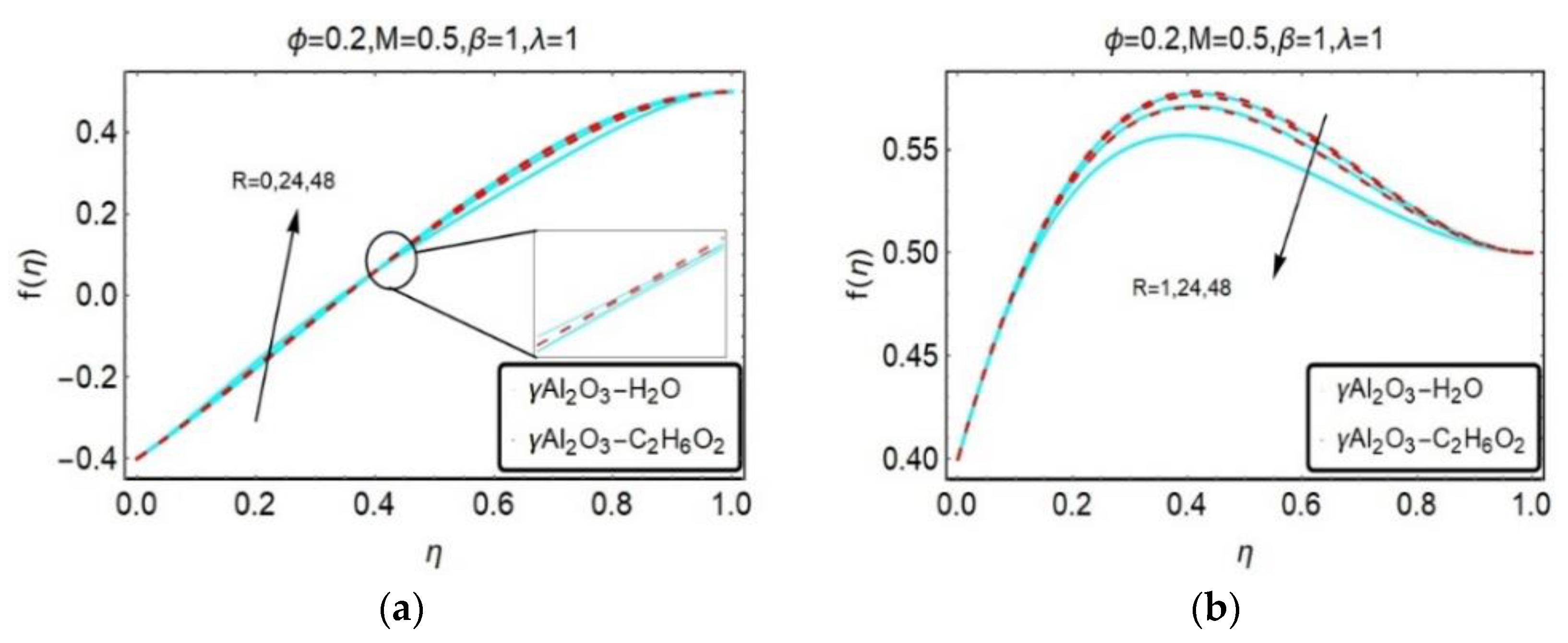
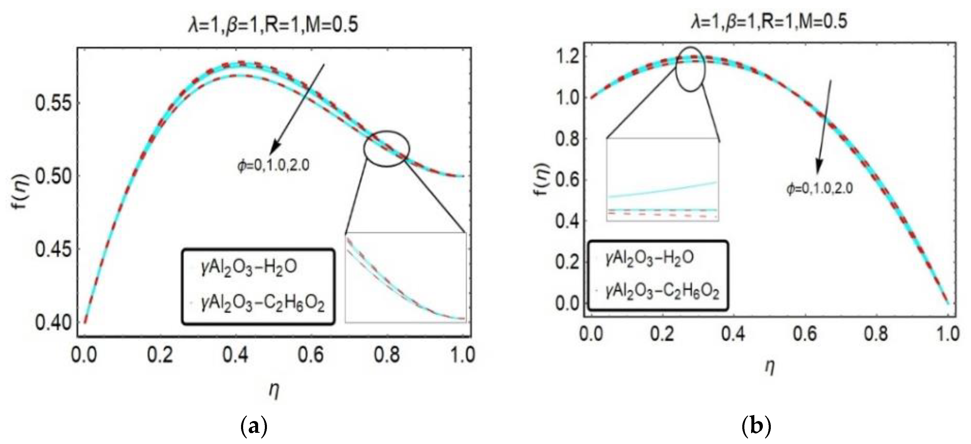
Figure 2, Figure 3, Figure 4, Figure 5 and Figure 6 highlight the variation in axial velocity f ( η ) under the influence of several emerging flow parameters such as rotation parameter R , squeeze parameter β , Hartmann number M , mixed convection parameter λ , and the volume fraction of the nanoparticle ϕ . Figure 2 is dedicated to uplift the axial velocity f ( η ) for different values of rotation parameter R . İt is observed that, for rising values of rotation parameter R , the axial velocity f ( η ) increases in the case of suction S > 0 , while, in the case of injection S < 0 , the reverse behavior is seen. Moreover, in the case of suction S > 0 , near the lower plate slightly reverse behavior is shown due to stretching parameter a . The effects of squeeze parameter, which is the ratio of characteristic parameter α to stretching parameter a depected in Figure 3. β > 0 stands for upper plate moves towards the lower plate on which fluid velocity increases and β < 0 indicates that upper plate fixed apart from the lower plate at distance h ( t ) . For the suction case S > 0 , the axial velocity decreases quite rapidly upon the rising values of squeeze parameter, while in the case of injection S < 0 , the velocity profile is opposite that of the suction. Figure 3 reflects the impact of electromagnetic forces to the viscous forces. For increasing values of Hartman number, the velocity profile decreases for both the suction and injection case because Lorentz forces tend to decrease the velocity for higher values of magnetic parameter. The effects of mixed convection parameter λ on the axial velocity illustrated in Figure 5. For the case of suction, the velocity profile decreases quite rapidly upon the enhancing values of mixed convection parameter. On the other hand, in the case of injection, the opposite behavior is noticed. The volume fraction parameter ϕ is portrayed in Figure 6. For rising values of volume fraction, the axial velocity decreases in the case of suction S > 0 . While, in the case of injection S < 0 , the velocity decreases upto the half of the channel and then increases on rising values volume fraction.
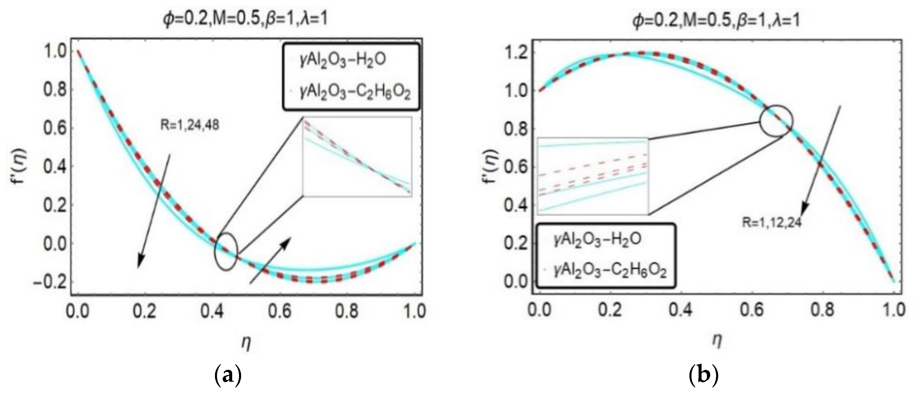
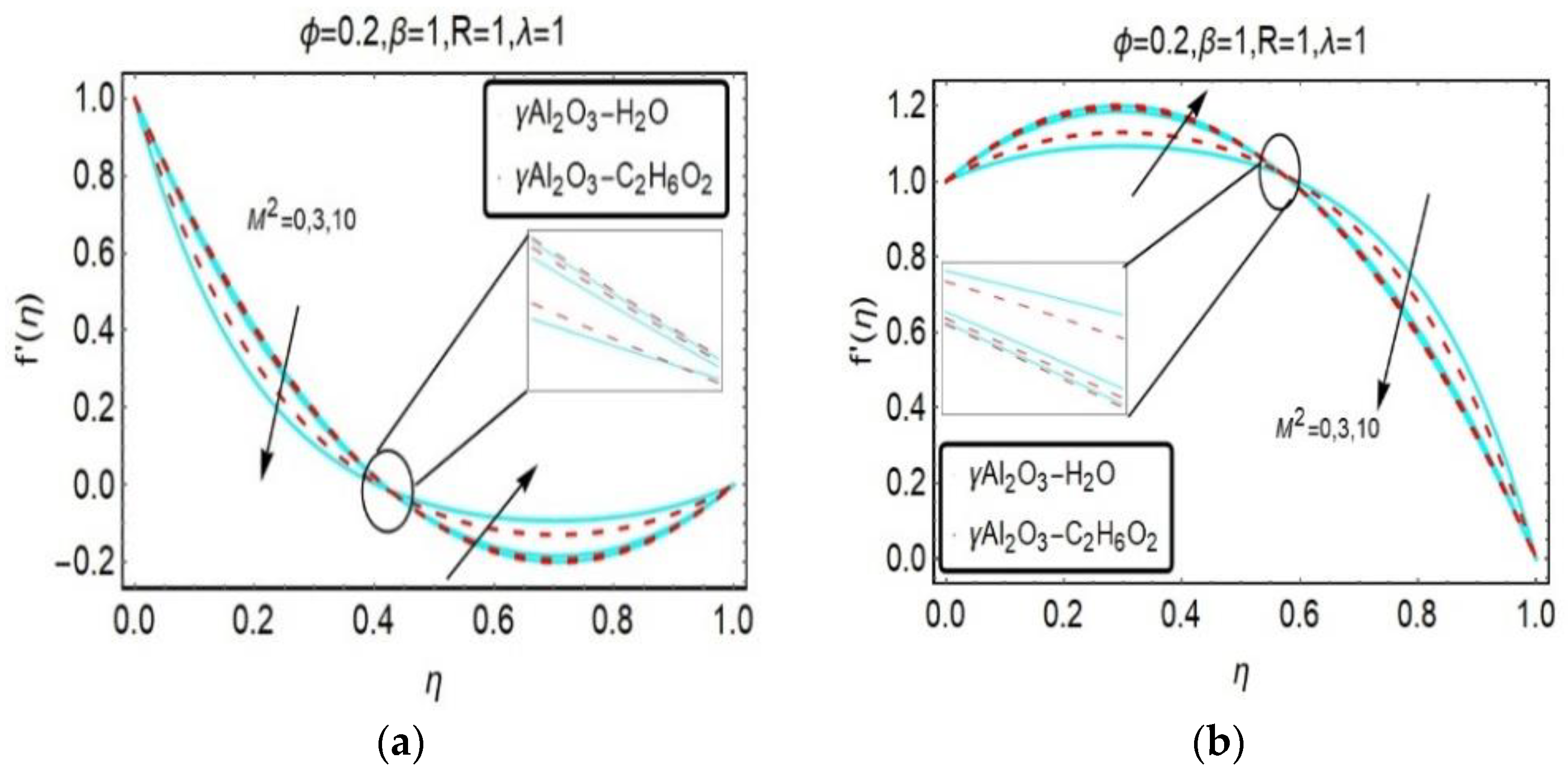
The uplifts of velocity field gradient f ( η ) with emerging parameters such as rotation parameter R , squeeze parameter β , ratio of electromagnetic forces to viscous forces M and mixed convection parameter λ are illustrated in Figure 7, Figure 8, Figure 9 and Figure 10. The effects of rotation parameter R on velocity gradiant f ( η ) reflected in Figure 7. For higher values of rotation parameter R , the velocity gradiant f ( η ) reduces in the upper half channel and then increases with increasing values of R in the case of suction S > 0 . Meanwhile, in the case of injection S < 0 , slightly reverse flow observed near the lower plate due to stretching factor a . Figure 8 depicts the impact of squeeze parameter β on the velocity gradiant field f ( η ) . One can easily seen that, for rising values of charectristic parameter to stretching parameter velocity gradiant increases for both the suction and injection cases. The uplifts of the ratio of electromagnetic to viscous force M 2 on f ( η ) reflected in Figure 9. For increasing values of Hartmann number, the velocity gradient initially reduced in the upper half channel and then increases with rising values of M 2 in the suction case. While, in the case of injection S < 0 , the opposite behavior is seen. However, in Figure 10, for rising values of mixed convection parameter λ , the velocity gradients for both the suction and injection cases look similar to that of the injection case in Figure 9b. On some extents change of decreasing in velocity occurs more rapidly for base fluid water with gamma- A l 2 O 3 suspended nano particles than that of base fluid ethylene glycol.
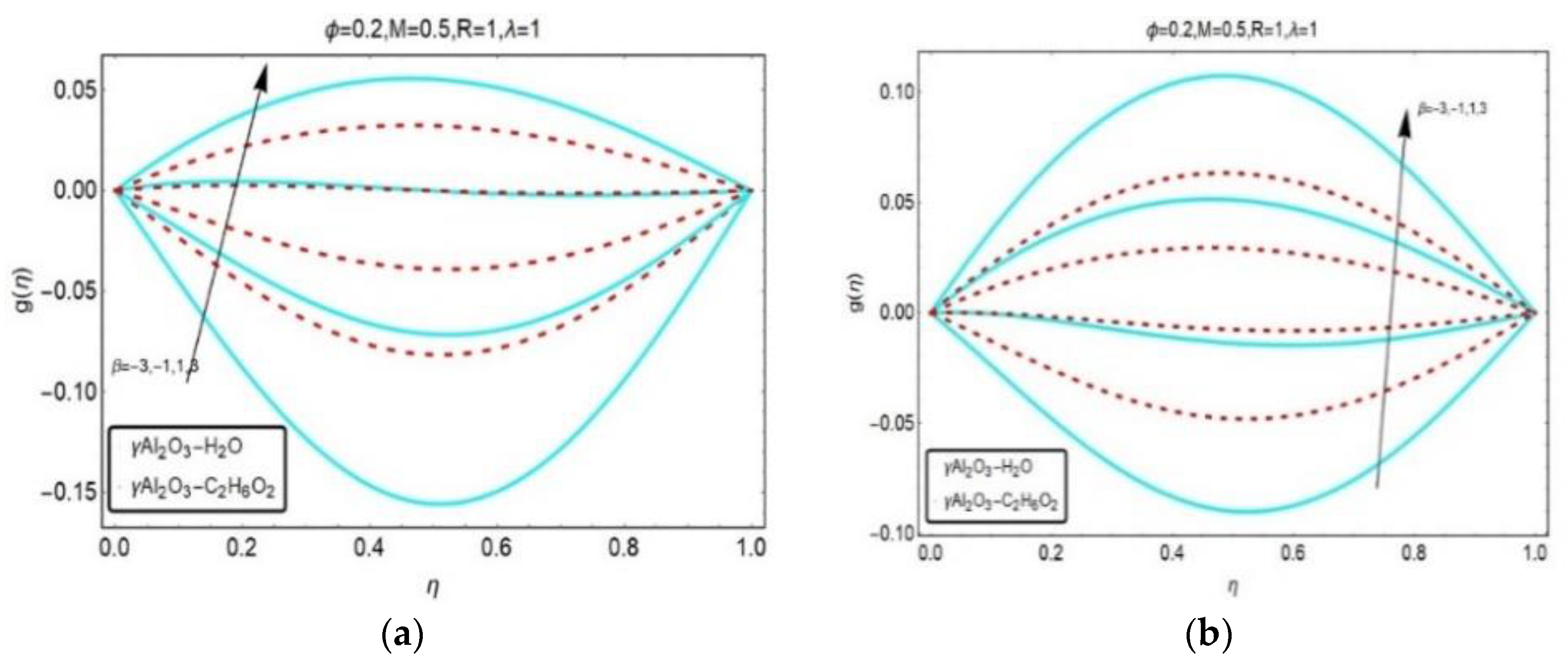
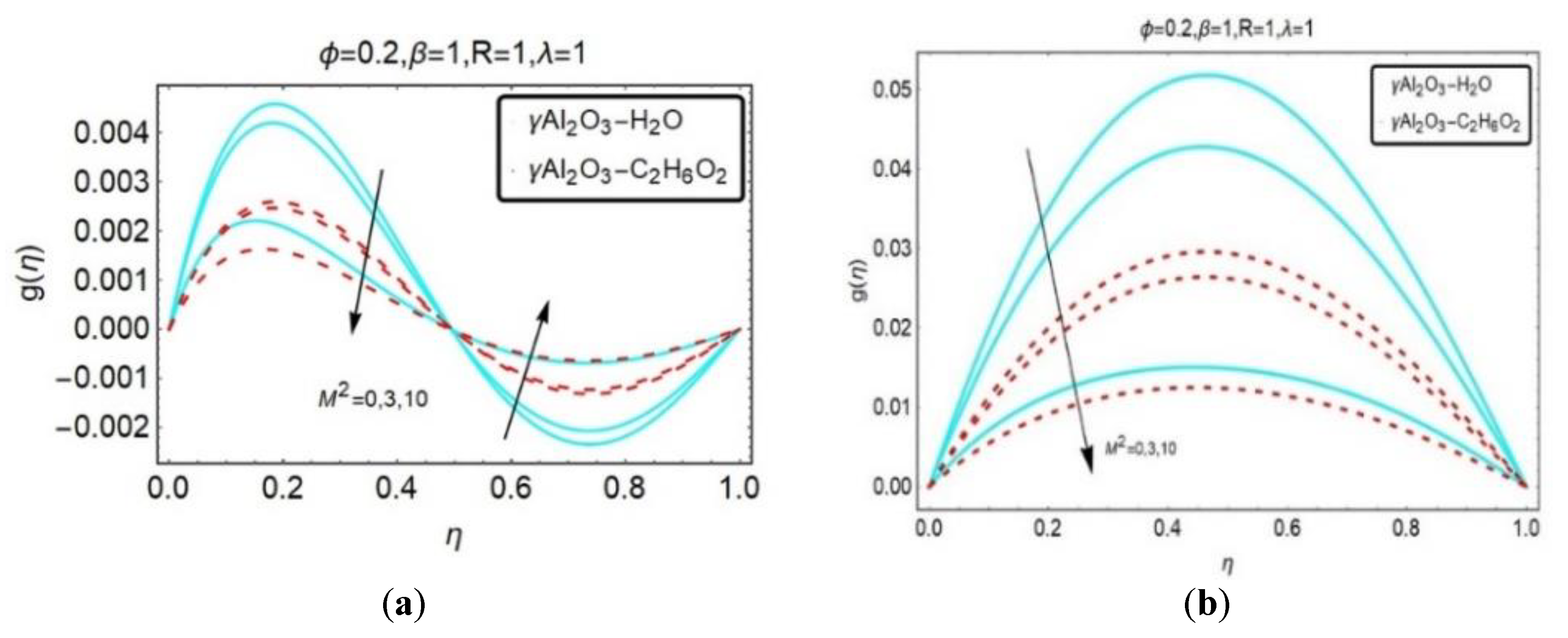
Effects of embedding parameters such volume fraction, ratio of electromagnetic to viscous forces, rotation parameter, quotient of characteristic to stretching factor and mixed convection parameter on angular velocity are portrayed in Figure 11, Figure 12, Figure 13, Figure 14 and Figure 15. The effects of rotation on velocity gradient illustrated in Figure 11. For increasing values of rotation parameter, the angular velocity g ( η ) reduced till η 0.5 and then increases for enhased values of rotation parameter in the case of suction S > 0 . While, in the case of injection S < 0 , the angular velocity increases with rising values of R . Figure 12 indicates that, the angular velocity enhanced with rising values squeeze parameter for both the suction and injection case. The uplifts of magnetic parameter, mixed convection and volume fraction on angular velocity are illustrated in Figure 13, Figure 14 and Figure 15. It is observed that, for increasing values of all these emerging parameters, angular velocity was initially reduced in the upper half channel in the case of suction S > 0 . On the other hand, in case of injection S < 0 , the angular velocity decreases for rising values of magnetic parameter and volume fraction. Meanwhile, for increasing values of mixed convection, quite the opposite behavior is seen.
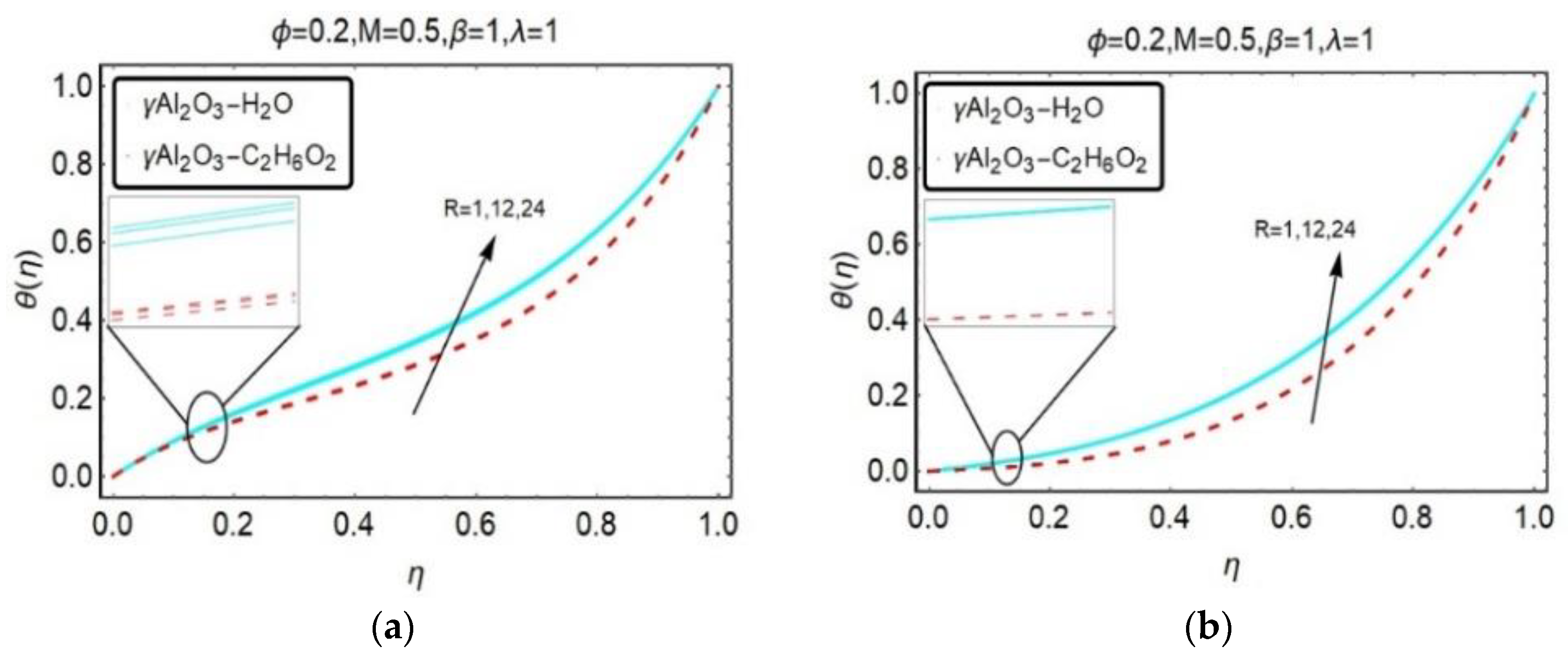
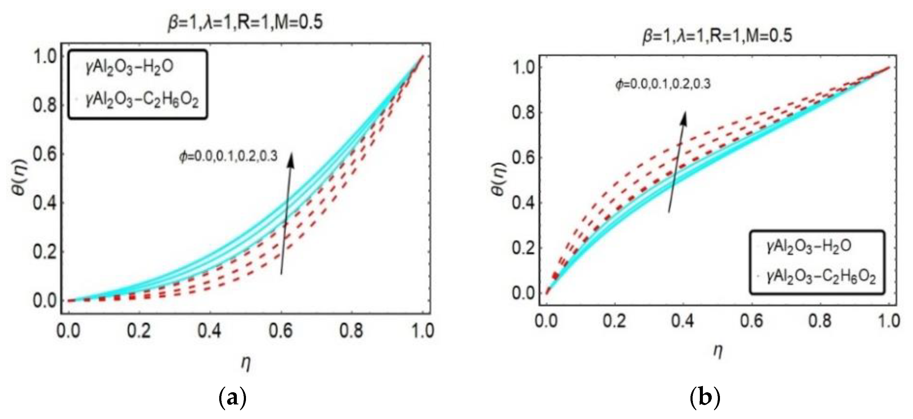
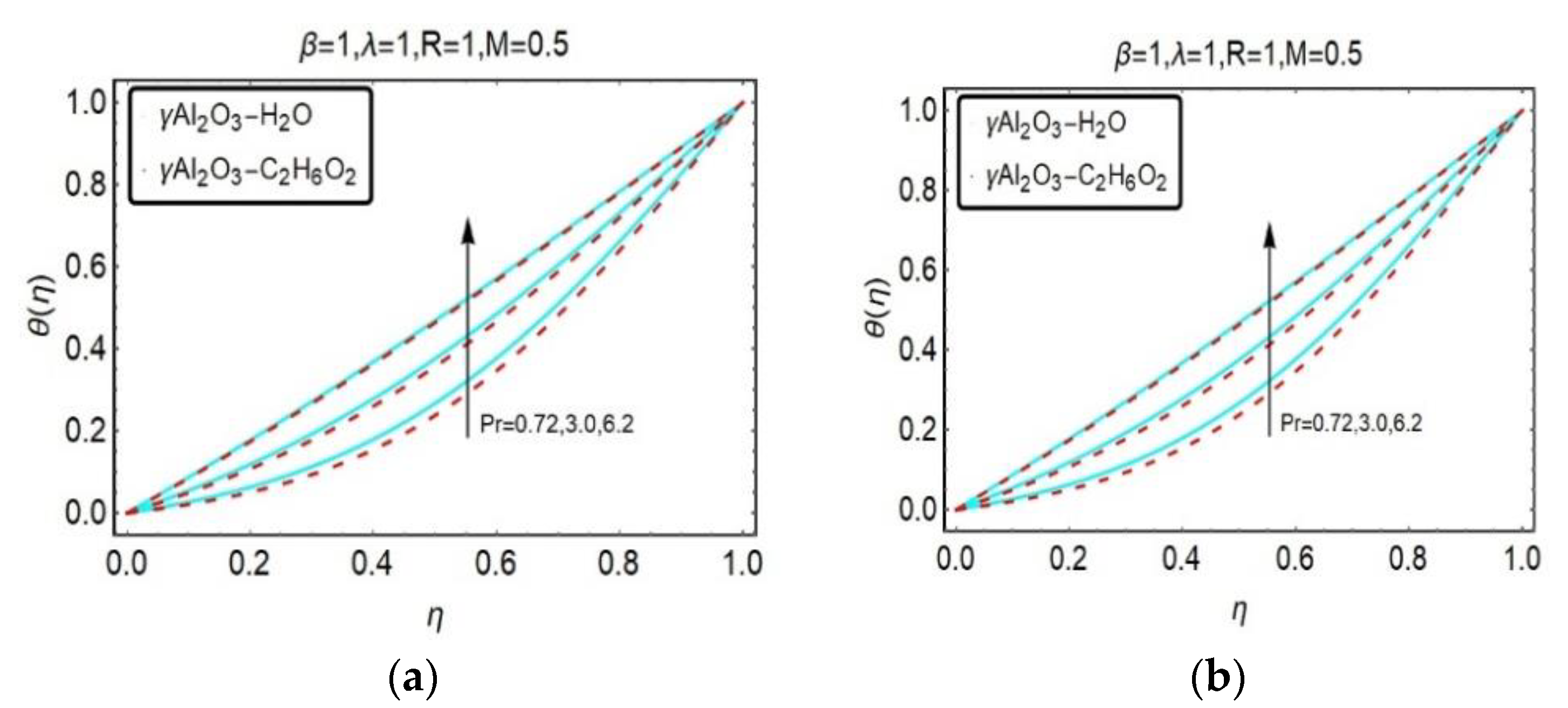
The upshots of embedding parameters such as Prandtl number, volume fraction, magnetic parameter, ratio of characteristic parameter to stretching factor, rotation parameter, and mixed convection parameter on temperature profile θ ( η ) are illustrated in Figure 16, Figure 17, Figure 18, Figure 19, Figure 20 and Figure 21. In Figure 16, Figure 17, Figure 18, Figure 19, Figure 20 and Figure 21, for both the suction and injection cases, the temperature profile enhanced with increasing value of these pertinent parameters except Figure 19b. Prandtl number also influences the temperature field of nanofluids like water and ethylene glycol suspended with gamma- A l 2 O 3 nanoparticles in increasing manner for both inhalation and injection.
To validate our flow model, a comparison of the present work with ϕ = 0 and M = 0.5 is illustrated in Table 2. It is observed that, the present study is in best agreement with the existing literature which proved the reality and novelty of the current study. Numerical results of skin friction coefficient and Nusselt number for γ Al 2 O 3 H 2 O and A l 2 O 3 C 2 H 6 O 2 are given in Table 3 and Table 4 respectively.

5. Conclusions

An unsteady 3D squeezing flow model comprising the aluminum and γ -aluminium oxide nanoparticles is used to observe the effect of mixed convection in a rotating channel. The system of nonlinear partial differential equation is reduced to a set of ordinary differential equation with the help of similarity transformation and the core findings form the given results as follows:
  • Enormous values of mixed convection parameter λ depict a significant effect on the velocity profile.
  • Temperature of the nanofluids is larger than the base fluid.
  • For rising values of β , the skin friction coefficient increases for both the γ A l 2 O 3 H 2 O and γ A l 2 O 3 C 2 H 6 O 2 . While, in the case of higher values of mixed convection parameter λ , the skin friction coefficient decreases.
  • Temperature of the γ A l 2 O 3 C 2 H 6 O 2 nanofluids is larger than the γ A l 2 O 3 H 2 O .
  • In the presence of γ A l 2 O 3 H 2 O and γ A l 2 O 3 C 2 H 6 O 2 nanoparticles, temperature profile increases.
  • For rising values of β , the skin friction coefficient increases for both the γ A l 2 O 3 H 2 O and γ A l 2 O 3 C 2 H 6 O 2 . Meanwhile, in the case of higher values of mixed convection parameter λ , the skin friction coefficient decreases.
  • In the absence of effective Prandtl number, the Nusselt number decreases. Meanwhile, in the presence of effective Prandtl number, the opposite behavior is seen.
  • For S > 0 and S < 0 , the axial velocity decreases with Hartmann parameter M .

Author Contributions

Formal analysis, U.K.; Investigation, N.Z. and A.Z.; Methodology, S.I.U.K.; Software, E.A. All authors have read and agreed to the published version of the manuscript.

Funding

This research received no external funding.

Acknowledgments

We are thankful to the editors and reviewers for their strong and positive comments, which made the paper more strength full.

Conflicts of Interest

The authors declare no conflict of interest.

References

  1. Stefan, M.J. Versuch uber die scheinbare adhesion. Sitzung Akad Wiss Math Nat. Tech. 1974, 69, 713–721. [Google Scholar]
  2. Reynolds, O. On the theory of lubrication and its application to Mr. Beauchamp Tower’s experiments, including an experimental determination of the viscosity of olive oil. Philos. Trans. R. Soc. Lond. 1886, 177, 157–234. [Google Scholar]
  3. Archibald, F.R. Load capacity and time relations for squeeze films. Trans. ASME 1956, 78, 29–35. [Google Scholar]
  4. Wolfe, W.A. Squeeze film pressures. Appl. Sci. Res. 1965, 14, 77–90. [Google Scholar] [CrossRef]
  5. Kuzma, D.C. Fluid inertia effects in squeeze films. Appl. Sci. Res. 1968, 18, 15–20. [Google Scholar] [CrossRef]
  6. Tichy, J.A.; Winer, W.O. Inertial considerations in parallel circular squeeze film bearings. J. Lubr. Technol. 1970, 92, 588–592. [Google Scholar] [CrossRef]
  7. Grimm, R.J. Squeezing flows of Newtonian liquid films: An analysis includes the fluid inertia. Appl. Sci. Res. 1976, 32, 149–166. [Google Scholar] [CrossRef]
  8. Wingstrand, S.L.; Alvarez, N.J.; Hassager, O.; Dealy, J.M. Oscillatory squeeze flow for the study of linear viscoelastic behaviour. J. Rheol. 2016, 60. [Google Scholar] [CrossRef] [Green Version]
  9. Munawar, S.; Mehmood, A.; Ali, A. Three-dimensional squeezing flow in a rotating channel of lower stretching porous wall. Comput. Math. Appl. 2012, 64, 1575–1586. [Google Scholar] [CrossRef] [Green Version]
  10. Mohyud-Din, S.T.; Khan, S.I.U.; Darus, M.; Hassan, S.M. Unsteady mixed convection squeezing flow of nanofluid between parallel disks. Adv. Mech. Eng. 2016, 8, 1–13. [Google Scholar] [CrossRef] [Green Version]
  11. Mohyud-Din, S.T.; Khan, S.I.U.; Mohsin, B. Velocity and temperature slip effects on squeezing flow of nanofluid between parallel disks in the presence of mixed convection. Neural Comput. Appl. 2017, 28, 169–182. [Google Scholar] [CrossRef]
  12. Choi, S.U.S. Enhancing thermal conductivity of fluids with nanoparticle. Dev. Appl. Non-Newton. Flows 1995, 231, 99–105. [Google Scholar]
  13. Agrawal, P.N.; Mohapatra, R.N.; Singh, U.H.M. Srivastava. In Mathematical Analysis and Its Applications; Springer: Roorkee, India, 2014. [Google Scholar]
  14. Kaufui, V.W.; Omar, D.L. Applications of Nanofluids: Current and future. Adv. Mech. Eng. 2009. [Google Scholar] [CrossRef] [Green Version]
  15. Kim, S.J.; Bang, I.C.; Buongiorno, J.; Hu, L.W. Study of pool boiling and critical heat flux enhancement in nanofluids. Bull. Pol. Acad. Sci. Tech. Sci. 2007, 55, 211–216. [Google Scholar]
  16. Kim, S.J.; Bang, I.C.; Buongiorno, J.; Hu, L.W. Surface wettability change during pool boiling of nanofluids and its effect on critical heat flux. Int. J. Heat Mass Transf. 2007, 50, 4105–4116. [Google Scholar] [CrossRef]
  17. Freidoonimehr, N.; Rostami, B.; Rashidi, M.M.; Momonia, E. Analytical modelling of three-dimensional squeezing nanofluid flow in a rotating channel on a lower stretching porous wall. Math. Probl. Eng. 2014, 14. [Google Scholar] [CrossRef] [Green Version]
  18. Sharif, M.A.R. Laminar mixed convection in shallow inclined driven cavities with hot moving lid on top and cooled from bottom. Appl. Therm. Eng. 2007, 27, 1036–1042. [Google Scholar] [CrossRef]
  19. Tiwari, R.K.; Das, M.K. Heat transfer augmentation in a two-sided lid-driven differentially heated square cavity utilizing nanofluids. Int. J. Heat Mass Transf. 2007, 50, 2002–2018. [Google Scholar] [CrossRef]
  20. Muthtamilselvan, M.; Kandaswamy, P.; Lee, J. Heat transfer enhancement of Copper-water nanofluids in a lid-driven enclosure. Commun. Nonlinear Sci. Numer. Simul. 2010, 15, 1501–1510. [Google Scholar] [CrossRef]
  21. Arefmanesh, A.; Mahmoodi, M. Effects of uncertainties of viscosity models for Al2O3–water nanofluid on mixed convection numerical simulations. Int. J. Therm. Sci. 2011, 50, 1706–1719. [Google Scholar] [CrossRef]
  22. Kandaswamy, P.; Sivasankaran, S.; Nithyadevi, N. Buoyancy-driven convection of water near its density maximum with partially active vertical walls. Int. J. Heat Mass Transf. 2007, 50, 942–948. [Google Scholar] [CrossRef]
  23. Mahmoodi, M. Mixed convection inside nanofluid filled rectangular enclosures with moving bottom wall. Therm. Sci. 2011, 15, 889–903. [Google Scholar] [CrossRef]
  24. Sebdani, S.M.; Mahmoodi, M.; Hashemi, S.M. Effect of nanofluid variable properties on mixed convection in a square cavity. Int. J. Therm. Sci. 2012, 52, 112–126. [Google Scholar] [CrossRef]
  25. Amiri, A.M.; Khanafer, K.M.; Pop, I. Numerical simulation of combined thermal and mass transport in a square lid-driven cavity. Int. J. Therm. Sci. 2007, 46, 662–671. [Google Scholar] [CrossRef]
  26. Arani, A.A.A.; Abbaszadeh, M.; Ardeshiri1, A. Mixed convection fluid flow and heat transfer and optimal distribution of discrete heat sources location in a cavity filled with nanofluid. Trans. Phenom. Nano-Micro Scales 2019, 5, 30–43. [Google Scholar]
  27. Mhiri, H.; El Golli, S.; Berthon, A.; Le Palec, G.; Bournot, P. Numerical study of the thermal and aerodynamic insulation of a cavity with a vertical downstream air jet. Int. Commun. Heat Mass Transf. 1998, 25, 919–928. [Google Scholar] [CrossRef]
  28. Gallo, M.; Astarita, T. PIV measurements in a rotating channel. In Proceedings of the 7th International Symposium on PIV (PIV2007), Rome, Italy, 11–14 September 2007. [Google Scholar]
  29. Khan, U.; Mohyud-Din, B.; Mohsin, B. Convective heat transfer and thermo-diffusion effects on flow of nanofluid towards a permeable stretching sheet saturated by a porous medium. Aerosp. Sci. Technol. 2016, 50, 196–203. [Google Scholar] [CrossRef]
  30. Khan, U.; Ahmad, N.; Touseef, S.M.D. Numerical investigation three dimensional squeezing flow of nanofluids in a rotating channel with lower stretching wall suspended by carbon nanotubes. Appl. Therm. Eng. 2017, 113, 1107–1117. [Google Scholar] [CrossRef]
  31. Rashidi, M.M.; Ganesh, N.V.; Hakeem, A.K.A.; Ganga, B.; Lorenzini, G. Influences of an effective Prandtl number model on nano boundary layer flow of c γ γ A l 2 O 3 H 2 O and γ γ A l 2 O 3 C 2 H 6 O 2 over a vertical stretching sheet. Int. J. Heat Mass Transf. 2016, 98, 616–623. [Google Scholar] [CrossRef]
  32. Mahanthesh, B.; Gorla, R.S.R.; Gireesha, B.J. Mixed convection squeezing three dimensional flow in a rotating channel filled with nanofluid. Int. J. Numer. Methods Heat Fluid Flow 2016, 26, 1460–1485. [Google Scholar] [CrossRef]
  33. Ahmed, N.; Adnan; Khan, U.; Mohyud-Din, S.T. Influence of an effective prandtl number model on squeezed flow of γ A l 2 O 3 H 2 O and γ A l 2 O 3 C 2 H 6 O 2 nanofluids. J. Mol. Liq. 2017, 238, 447–454. [Google Scholar] [CrossRef]
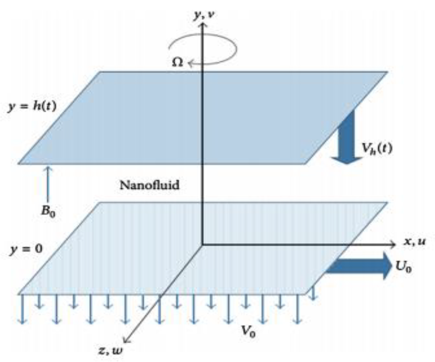
Figure 1. Schematic diagram of the flow model.
Energies 13 03138 g001
Figure 2. Influence of R on f ( η ) for (a) S > 0 and (b) S < 0 .
Energies 13 03138 g002
Figure 3. Influence of β on f ( η ) for (a) S > 0 and (b) S < 0 .
Energies 13 03138 g003
Figure 4. Influence of M 2 on f ( η ) for (a) S > 0 and (b) S < 0 .
Energies 13 03138 g004
Figure 5. Influence of λ on f ( η ) for (a) S > 0 and (b) S < 0 .
Energies 13 03138 g005
Figure 6. Influence of ϕ on f ( η ) for (a) S > 0 and (b) S < 0 .
Energies 13 03138 g006
Figure 7. Influence of R on f ( η ) for (a) S > 0 and (b) S < 0 .
Energies 13 03138 g007
Figure 8. Influence of β on f ( η ) for (a) S > 0 and (b) S < 0 .
Energies 13 03138 g008
Figure 9. Influence of M 2 on f ( η ) for (a) S > 0 and (b) S < 0 .
Energies 13 03138 g009
Figure 10. Influence of λ on f ( η ) for (a) S > 0 and (b) S < 0 .
Energies 13 03138 g010
Figure 11. Influence of R on g ( η ) for (a) S > 0 and (b) S < 0 .
Energies 13 03138 g011
Figure 12. Influence of β on g ( η ) for (a) S > 0 and (b) S < 0 .
Energies 13 03138 g012
Figure 13. Influence of M 2 on g ( η ) for (a) S > 0 and (b) S < 0 .
Energies 13 03138 g013
Figure 14. Influence of λ on g ( η ) for (a) S > 0 and (b) S < 0 .
Energies 13 03138 g014
Figure 15. Influence of ϕ on g ( η ) for (a) S > 0 and (b) S < 0 .
Energies 13 03138 g015
Figure 16. Influence of R on θ ( η ) for (a) S > 0 and (b) S < 0 .
Energies 13 03138 g016
Figure 17. Influence of β on θ ( η ) for (a) S > 0 and (b) S < 0 .
Energies 13 03138 g017
Figure 18. Influence of M 2 on θ ( η ) for (a) S > 0 and (b) S < 0 .
Energies 13 03138 g018
Figure 19. Influence of λ on θ ( η ) for (a) S > 0 and (b) S < 0 .
Energies 13 03138 g019
Figure 20. Influence of ϕ on θ ( η ) for (a) S > 0 and (b) S < 0 .
Energies 13 03138 g020
Figure 21. Influence of P r on θ ( η ) for (a) S > 0 and (b) S < 0 .
Energies 13 03138 g021
Table 1. Thermophysical properties of the flow models for gamma-alumina nanoparticles.
Model ρ (kg/m3) C p (kg−1K−1) k  (Wm−1K−1) σ P r
H 2 O 997.141790.6130.0056.96
C 2 H 6 O 2 1116.623820.2495.5 × 10−6204
A l 2 O 3 3970765403.5 ×107
Table 2. Comparison with existing literature for ϕ = 0 ,   M = 0.5 .
β R S f ( 0 ) f ( 1 )
Present[9]Present[9]
1.0 2.0 0.5 10.53119500 10.5311950 7.70317226 7.7031724
0.0 7.58900683 7.5890069 4.82359091 4.8235909
1.0 4.51255172 4.5125517 1.80917188 1.8091719
2.0 1.28942091 1.2894209 1.35422925 1.3542292
3.0 2.08350344 2.0835034 4.67005029 4.6700503
Table 3. Numerical results of skin friction coefficient and Nusselt number for γ A l 2 O 3 H 2 O
R M 2 λ β f ( 1 ) θ ( 1 )
S > 0 S < 0 S > 0 S < 0
10.513−21.9385−44.91420.3183710.580722
2−7.74985−30.41130.1528640.427103
16.26419−16.08−0.0245440.262825
020.1085−1.92094−0.2152650.0866754
−134.529912.0847−0.421818−0.102728
−247.158325.8305−0.643296−0.307139
60.44439.4562−0.884845−0.528295
016.29071−16.0491−0.02460380.262761
1003.62675−19.1475−0.01862880.269122
300−1.77226−25.3733−0.006693140.281661
Table 4. Numerical results of skin friction coefficient and Nusselt number for γ A l 2 O 3 C 2 H 6 O 2
R M 2 λ β f ( 1 ) θ ( 1 )
S > 0 S < 0 S > 0 S < 0
10.513−21.9377−44.91310.3183660.580717
2−7.74947−30.41060.152860.427098
16.26428−16.0801−0.02454760.262821
020.1129−1.92194−0.2152750.0866763
−133.608414.7246−0.42067−0.0975386
−247.147125.8336−0.643222−0.307105
−360.355839.4142−0.884469−0.528115
016.29071−16.0491−0.02460380.262761
10013.63485−19.1493−0.01898690.268752
3001−1.75006−25.3634−0.007773030.280488