Detection of Partial Demagnetization Faults in Five-Phase Permanent Magnet Assisted Synchronous Reluctance Machines


Abstract
:
1. Introduction
2. The Five-Phase Ferrite-Assisted fPMa-SynRM and Validation of the FEA Model
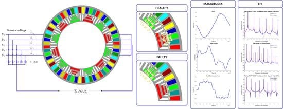
2.1. The fPMa-SynRM
2.2. The FEA Model of the fPMa-SynRM
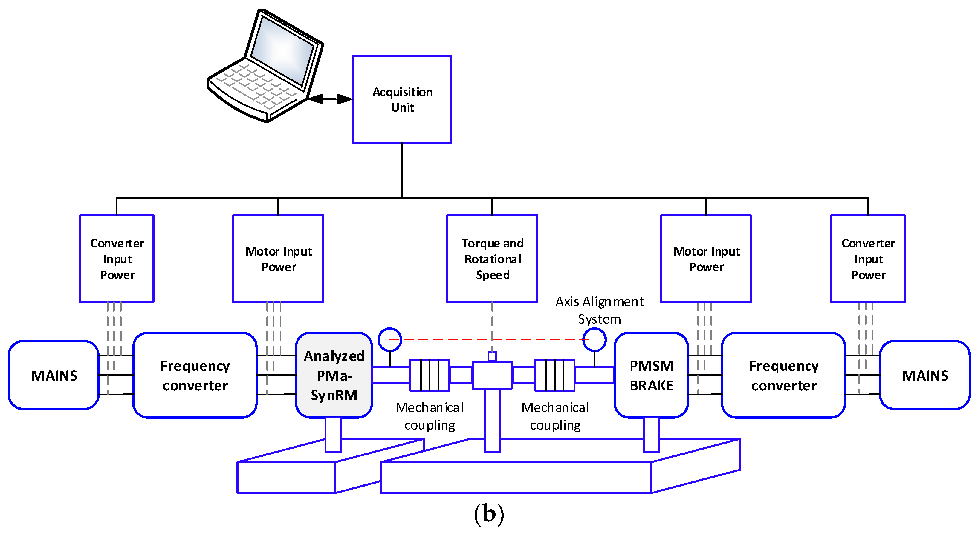
2.3. The Validation of the FEA Model
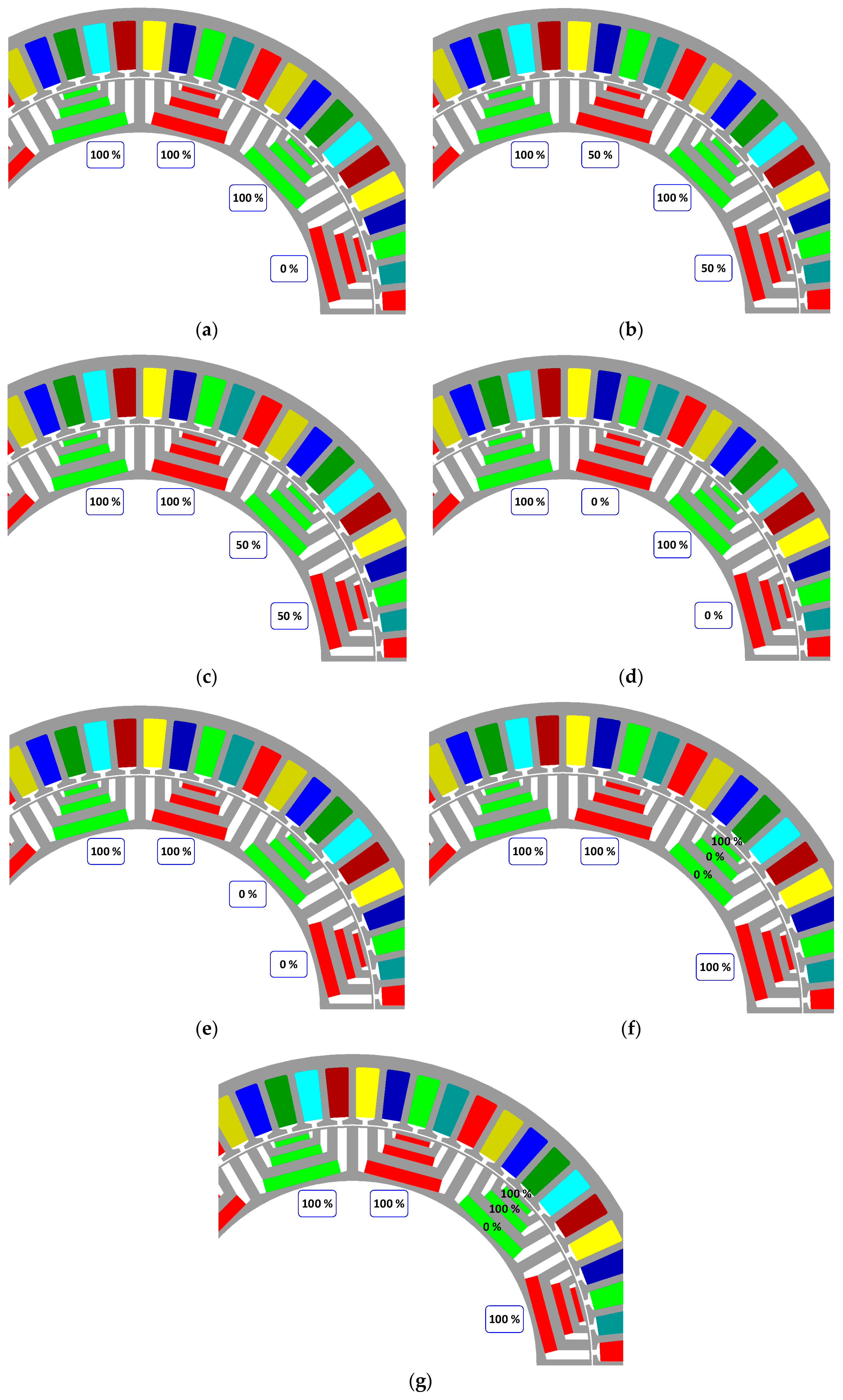
3. Analyzed Partial Demagnetization Faults
- ■
- Case 1. One magnetic pole 100% demagnetized. This case corresponds to 1/12 demagnetized magnets, i.e., 8.3% demagnetization.
- ■
- Case 2. Two adjacent north magnetic poles 50% demagnetized. This case corresponds to 8.3% demagnetization.
- ■
- Case 3. Two adjacent north-south magnetic poles 50% demagnetized. This case corresponds to 8.3% demagnetization.
- ■
- Case 4. Two adjacent north magnetic poles 100% demagnetized. This case corresponds to 16.7% demagnetization.
- ■
- Case 5. Two adjacent north-south magnetic poles 100% demagnetized. This case corresponds to 16.7% demagnetization.
- ■
- Case 6. Two magnets of the same pole 100% demagnetized. This case corresponds to 7.4% demagnetization.
- ■
- Case 7. Only one magnet 100% demagnetized. This case corresponds to 5.0% demagnetization.
4. Results Under Healthy and Partial Demagnetization
5. Fault Indicators to Detect Demagnetization Faults
6. Conclusions
Supplementary Materials
Supplementary File 1Author Contributions
Funding
Conflicts of Interest
Nomenclature
| ia,b,c,d,e | Phase currents (A) |
| id | d-axis current (A) |
| iq | q-axis current (A) |
| va,b,c,d,e | Phase voltage (V) |
| vZSVC | Homopolar voltage (V) |
| fs | Electrical frequency (Hz) |
| p | Pole pairs (-) |
| Ra,b,c,d,e | Phase resistance (Ω) |
| Ld | d-axis inductance (H) |
| Lq | q-axis inductance (H) |
| θ | Rotor position (electrical °) |
| α | Current angle (electrical °) |
| EMF | Electromotive force |
| FEA | Finite element analysis |
| FFT | Fast Fourier transform |
| fPMa-SynRM | Ferrite-assisted synchronous reluctance motor |
| MCSA | Motor current signature analysis |
| PF | Power factor |
| PM | Permanent magnet |
| PMa-SynRM | Permanent magnet assisted synchronous reluctance motor |
| ZSVC | Zero-sequence voltage component |
References
- Ngo, D.K.; Hsieh, M.F. Performance Analysis of Synchronous Reluctance Motor with Limited Amount of Permanent Magnet. Energies 2019, 12, 3504. [Google Scholar] [CrossRef] [Green Version]
- Riba, J.-R.; López-Torres, C.; Romeral, L.; Garcia, A. Rare-earth-free propulsion motors for electric vehicles: A technology review. Renew. Sustain. Energy Rev. 2016, 57, 367–379. [Google Scholar] [CrossRef] [Green Version]
- Mahmoud, H.; Bianchi, N. Eccentricity in synchronous reluctance motors—Part I: Analytical and finite-element models. IEEE Trans. Energy Convers. 2015, 30, 745–753. [Google Scholar] [CrossRef]
- Zhu, X.; Wu, W.; Quan, L.; Xiang, Z.; Gu, W. Design and multi-objective stratified optimization of a less-rare-earth hybrid permanent magnets motor with high torque density and low cost. IEEE Trans. Energy Convers. 2018, 34, 1178–1189. [Google Scholar] [CrossRef]
- Ibrahim, M.; Pillay, P. Aligning the Reluctance and Magnet Torque in Permanent Magnet Synchronous Motors for Improved Performance. In Proceedings of the 2018 IEEE Energy Conversion Congress and Exposition, ECCE, Portland, OR, USA, 23–27 September 2018; Institute of Electrical and Electronics Engineers Inc.: Piscataway, NJ, USA, 2018; pp. 2286–2291. [Google Scholar]
- Hayslett, S.; Strangas, E. Design and analysis of aligned axis interior permanent magnet machines considering saturation. In Proceedings of the 2019 IEEE International Electric Machines and Drives Conference, IEMDC, San Diego, CA, USA, 12–15 May 2019; Institute of Electrical and Electronics Engineers Inc.: Piscataway, NJ, USA, 2019; pp. 686–692. [Google Scholar]
- López-Torres, C.; Riba, J.-R.; Garcia, A.; Romeral, L. Detection of eccentricity faults in five-phase ferrite-PM assisted synchronous reluctance machines. Appl. Sci. 2017, 7, 565. [Google Scholar] [CrossRef] [Green Version]
- Vagati, A.; Boazzo, B.; Guglielmi, P.; Pellegrino, G. Design of ferrite-assisted synchronous reluctance machines robust toward demagnetization. IEEE Trans. Ind. Appl. 2014, 50, 1768–1779. [Google Scholar] [CrossRef] [Green Version]
- Zhu, M.; Yang, B.; Hu, W.; Feng, G.; Kar, N.C. Vold-Kalman Filtering Order Tracking Based Rotor Demagnetization Detection in PMSM. IEEE Trans. Ind. Appl. 2019, 55, 5768–5778. [Google Scholar] [CrossRef]
- Gao, C.; Nie, Y.; Si, J.; Fu, Z.; Feng, H. Mode Recognition and Fault Positioning of Permanent Magnet Demagnetization for PMSM. Energies 2019, 12, 1644. [Google Scholar] [CrossRef] [Green Version]
- Urresty, J.C.J.-C.; Riba, J.R.J.-R.; Romeral, L. Diagnosis of interturn faults in pmsms operating under nonstationary conditions by applying order tracking filtering. IEEE Trans. Power Electron. 2013, 28, 507–515. [Google Scholar] [CrossRef]
- Romary, R.; Demian, C.; Schlupp, P.; Roger, J.-Y. Offline and online methods for stator core fault detection in large generators. IEEE Trans. Ind. Electron. 2013, 60, 4084–4092. [Google Scholar] [CrossRef]
- Candelo-Zuluaga, C.; Riba, J.-R.; López-Torres, C.; Garcia, A. Detection of Inter-Turn Faults in Multi-Phase Ferrite-PM Assisted Synchronous Reluctance Machines. Energies 2019, 12, 2733. [Google Scholar] [CrossRef] [Green Version]
- Faiz, J.; Mazaheri-Tehrani, E. Demagnetization modeling and fault diagnosing techniques in permanent magnet machines under stationary and nonstationary conditions: An overview. IEEE Trans. Ind. Appl. 2017, 53, 2772–2785. [Google Scholar] [CrossRef]
- Cusido, J.; Romeral, L.; Ortega, J.A.; Garcia, A.; Riba, J.R. Wavelet and PDD as fault detection techniques. Electr. Power Syst. Res. 2010, 80, 915–924. [Google Scholar] [CrossRef]
- Huang, B.; Feng, G.; Tang, X.; Gu, J.X.; Xu, G.; Cattley, R.; Gu, F.; Ball, A.D.; Huang, B.; Feng, G.; et al. A performance evaluation of two bispectrum analysis methods applied to electrical current signals for monitoring induction motor-driven systems. Energies 2019, 12, 1438. [Google Scholar] [CrossRef] [Green Version]
- Ilamparithi, T.; Nandi, S. Analysis, modeling and simulation of static eccentric reluctance synchronous motor. In Proceedings of the 8th IEEE Symposium on Diagnostics for Electrical Machines, Power Electronics & Drives, Bologna, Italy, 5–8 September 2011; pp. 45–50. [Google Scholar]
- Giantomassi, A.; Ferracuti, F.; Iarlori, S.; Ippoliti, G.; Longhi, S. Electric Motor Fault Detection and Diagnosis by Kernel Density Estimation and KKullback—Leibler Divergence Based on Stator Current Measurements. IEEE Trans. Ind. Electron. 2015, 62, 1770–1780. [Google Scholar] [CrossRef]
- Choi, S.; Haque, M.S.; Arafat, A.; Toliyat, H. Detection and estimation of extremely small fault signature by utilizing multiple current sensor signals in multiphase electric machines. IEEE Trans. Ind. Appl. 2017, 53, 2805–2816. [Google Scholar] [CrossRef]
- Saavedra, H.; Urresty, J.-C.; Riba, J.-R.; Romeral, L. Detection of interturn faults in PMSMs with different winding configurations. Energy Convers. Manag. 2014, 79, 534–542. [Google Scholar] [CrossRef]
- Urresty, J.C.; Riba, J.R.; Delgado, M.; Romeral, L. Detection of demagnetization faults in surface-mounted permanent magnet synchronous motors by means of the zero-sequence voltage component. IEEE Trans. Energy Convers. 2012, 27, 42–51. [Google Scholar] [CrossRef]
- Lee, S.B.; Hyun, D.; Kang, T.; Yang, C.; Shin, S.; Kim, H.; Park, S.; Kong, T.-S.; Kim, H.-D. Identification of false rotor fault indications produced by online mcsa for medium-voltage induction machines. IEEE Trans. Ind. Appl. 2016, 52, 729–739. [Google Scholar] [CrossRef]
- Saavedra, H.; Riba, J.-R.; Romeral, L. Detection of inter-turn faults in five-phase permanent magnet synchronous motors. Adv. Electr. Comput. Eng. 2014, 14, 49–54. [Google Scholar] [CrossRef] [Green Version]
- Urresty, J.-C.; Riba, J.-R.; Romeral, L. Influence of the stator windings configuration in the currents and zero-sequence voltage harmonics in permanent magnet synchronous motors with demagnetization faults. IEEE Trans. Magn. 2013, 49, 4885–4893. [Google Scholar] [CrossRef]
- Vartanian, R.; Toliyat, H.A.; Akin, B.; Poley, R. Power factor improvement of synchronous reluctance motors (SynRM) using permanent magnets for drive size reduction. In Proceedings of the Conference Proceedings-IEEE Applied Power Electronics Conference and Exposition—APEC, Orlando, FL, USA, 5–9 February 2012; pp. 628–633. [Google Scholar]
- Faiz, J.; Jafari, A. Interturn fault diagnosis in brushless direct current motors—A review. In Proceedings of the 2018 IEEE International Conference on Industrial Technology (ICIT), IEEE, Lyon, France, 20–22 February 2018; pp. 437–444. [Google Scholar]
- Ullah, Z.; Hur, J. A comprehensive review of winding short circuit fault and irreversible demagnetization fault detection in PM type machines. Energies 2018, 11, 3309. [Google Scholar] [CrossRef] [Green Version]
- Schramberg Hard Ferrite Magnets. Strontium Ferrite HF 30/26. Available online: https://www.magnete.de/fileadmin/user_upload/Content/Produkte/PDF/Gesinterte_HF_Magnete/HF_30-26_E.pdf (accessed on 15 June 2020).


| Characteristics | Value |
|---|---|
| Phase number | 5 |
| Nominal power (kW) | 3.5 |
| Nominal voltage (VRMS) | 240 |
| Nominal current (ARMS) | 4 |
| Nominal torque (N·m) | 5.7 |
| Nominal speed (rev/min) | 5000 |
| Alignment torque/total torque * | 43.14% |
| Reluctant torque/total torque * | 56.86% |
| Pole pairs (p) | 6 |
| External stator diameter (mm) | 162.8 |
| External rotor diameter (mm) | 114 |
| Laminations length (mm) | 26 |
| Air gap (mm) | 0.3 |
| Slots number | 60 |
| Conductors/slot | 60 |
| Slots per pole and per phase (q) | 1 |
| Winding type | Double layer |
| Permanent magnets material | Ferrite HF 30/26 |
| Steel laminations | M330-35A |
| Ld (mH) | 15.9 under maximum current (id = iline,max,peak,1 **, iq = 0) 59.7 under no current (id = iq = 0) |
| Lq (mH) | 11.8 under maximum current (id = 0, iq = iline,max,peak,1 **) 15.2 under no current (id = iq = 0) |
| Harmonic Order | 1 | 2 | 3 | 4 | 5 | 6 | 7 | 8 | 9 |
|---|---|---|---|---|---|---|---|---|---|
| Case 1. One magnetic pole 100% demagnetized | |||||||||
| Healthy (V) | 121.30 | ‒ | 17.91 | ‒ | 0.76 | ‒ | 5.35 | ‒ | 16.67 |
| Demagnetized (V) | 114.30 | ‒ | 16.73 | ‒ | 0.56 | ‒ | 4.63 | ‒ | 14.92 |
| Case 2. Two adjacent north magnetic poles 50% demagnetized | |||||||||
| Healthy (V) | 121.30 | ‒ | 17.91 | ‒ | 0.76 | ‒ | 5.35 | ‒ | 16.67 |
| Demagnetized (V) | 111.20 | 1.57 × 10⁻³ | 16.68 | 2.38 × 10⁻³ | 9.76 × 10⁻³ | 2.24 × 10⁻³ | 3.95 | 2.65 × 10⁻³ | 13.35 |
| Case 3. Two adjacent north-south magnetic poles 50% demagnetized | |||||||||
| Healthy (V) | 121.30 | ‒ | 17.91 | ‒ | 0.76 | ‒ | 5.35 | ‒ | 16.67 |
| Demagnetized (V) | 108.10 | 2.51 × 10⁻³ | 16.24 | 2.88 × 10⁻³ | 0.44 | 2.25 × 10⁻³ | 4.83 | 2.27 × 10⁻³ | 14.61 |
| Case 4. Two adjacent north magnetic poles 100% demagnetized | |||||||||
| Healthy (V) | 121.30 | ‒ | 17.91 | ‒ | 0.76 | ‒ | 5.35 | ‒ | 16.67 |
| Demagnetized (V) | 107.50 | 1.15 × 10⁻³ | 15.52 | 8.69 × 10⁻⁴ | 0.38 | 6.29 × 10⁻⁴ | 3.88 | 5.58 × 10⁻⁴ | 13.29 |
| Case 5. Two adjacent north-south magnetic poles 100% demagnetized | |||||||||
| Healthy (V) | 121.30 | ‒ | 17.91 | ‒ | 0.76 | ‒ | 5.35 | ‒ | 16.67 |
| Demagnetized (V) | 101.80 | 4.29 × 10⁻⁴ | 15.01 | 5.23 × 10⁻⁴ | 0.57 | 3.42 × 10⁻⁴ | 4.51 | 4.22 × 10⁻⁴ | 13.67 |
| Case 6. Two magnets of the same pole 100% demagnetized | |||||||||
| Healthy (V) | 121.30 | ‒ | 17.91 | ‒ | 0.76 | ‒ | 5.35 | ‒ | 16.67 |
| Demagnetized (V) | 114.9 | - | 16.85 | - | 0.64 | 4.71 | 15.11 | ||
| Case 7. One magnet 100% demagnetized | |||||||||
| Healthy (V) | 121.30 | ‒ | 17.91 | ‒ | 0.76 | ‒ | 5.35 | ‒ | 16.67 |
| Demagnetized (V) | 116.50 | - | 17.02 | - | 0.72 | - | 4.82 | - | 15.40 |
| Harmonic Order | 1 | 2 | 3 | 4 | 5 | 6 | 7 | 8 | 9 |
|---|---|---|---|---|---|---|---|---|---|
| Case 1. One magnetic pole 100% demagnetized. Maximum id current | |||||||||
| Healthy (A) | 5.01 | ‒ | 2.54 | ‒ | 3.25 × 10⁻³ | ‒ | 0.91 | ‒ | 0.15 |
| Demagnetized (A) | 4.90 | 1.6 × 10⁻³ | 2.49 | 3.83 × 10⁻⁴ | 1.40 × 10⁻⁴ | 6.22 × 10⁻⁴ | 0.84 | 1.77 × 10⁻⁴ | 0.14 |
| Case 2. Two adjacent north magnetic poles 50% demagnetized. Maximum id current | |||||||||
| Healthy (A) | 5.01 | ‒ | 2.54 | ‒ | 3.25 × 10⁻³ | ‒ | 0.91 | ‒ | 0.15 |
| Demagnetized (A) | 4.84 | 0.11 | 2.46 | 0.03 | 0.01 | 0.05 | 0.54 | 0.01 | 0.15 |
| Case 3. Two adjacent north-south magnetic poles 50% demagnetized. Maximum id current | |||||||||
| Healthy (A) | 5.01 | ‒ | 2.54 | ‒ | 3.25 × 10⁻³ | ‒ | 0.91 | ‒ | 0.15 |
| Demagnetized (A) | 4.84 | 0.03 | 2.46 | 7.57 × 10⁻³ | 3.43 × 10⁻³ | 0.01 | 0.84 | 3.17 × 10⁻³ | 0.14 |
| Case 4. Two adjacent north magnetic poles 100% demagnetized. Maximum id current | |||||||||
| Healthy (A) | 5.01 | ‒ | 2.54 | ‒ | 3.25 × 10⁻³ | ‒ | 0.91 | ‒ | 0.15 |
| Demagnetized (A) | 4.80 | 0.01 | 2.45 | 2.24 × 10⁻³ | 1.02 × 10⁻³ | 3.53 × 10⁻³ | 0.81 | 1.09 × 10⁻³ | 0.14 |
| Case 5. Two adjacent north-south magnetic poles 100% demagnetized. Maximum id current | |||||||||
| Healthy (A) | 5.01 | ‒ | 2.54 | ‒ | 3.25 × 10⁻³ | ‒ | 0.91 | ‒ | 0.15 |
| Demagnetized (A) | 4.79 | 9.50 × 10⁻³ | 2.39 | 2.33 × 10⁻³ | 1.06 × 10⁻³ | 3.40 × 10⁻³ | 0.75 | 9.96 × 10⁻⁴ | 0.12 |
| Case 6. Two magnets of the same pole 100% demagnetized | |||||||||
| Healthy (A) | 5.01 | ‒ | 2.54 | ‒ | 3.25 × 10⁻³ | ‒ | 0.91 | ‒ | 0.15 |
| Demagnetized (A) | 4.89 | 0.07 | 2.50 | 0.02 | 8.23 × 10⁻³ | 0.03 | 0.85 | 7.60 × 10⁻³ | 0.14 |
| Case 7. One magnet 100% demagnetized | |||||||||
| Healthy (A) | 5.01 | ‒ | 2.54 | ‒ | 3.25 × 10⁻³ | ‒ | 0.91 | ‒ | 0.15 |
| Demagnetized (A) | 4.89 | 0.04 | 2.50 | 9.10 × 10⁻³ | 4.24 × 10⁻³ | 0.01 | 0.88 | 3.60 × 10⁻³ | 0.14 |
| Harmonic Order | 1 | 2 | 3 | 4 | 5 | 6 | 7 | 8 | 9 |
|---|---|---|---|---|---|---|---|---|---|
| Case 1. One magnetic pole 100% demagnetized. Maximum id current | |||||||||
| Healthy (V) | 26.71 | ‒ | 2.52 | ‒ | 0.40 | ‒ | 0.39 | ‒ | 0.46 |
| Demagnetized (V) | 26.39 | 3.47 × 10⁻³ | 2.09 | 1.00 × 10⁻³ | 0.50 | 7.01 × 10⁻⁴ | 0.22 | 5.94 × 10⁻⁴ | 0.45 |
| Case 2. Two adjacent north magnetic poles 50% demagnetized. Maximum id current | |||||||||
| Healthy (V) | 26.71 | ‒ | 2.52 | ‒ | 0.40 | ‒ | 0.39 | ‒ | 0.46 |
| Demagnetized (V) | 26.28 | 0.03 | 2.03 | 0.02 | 0.46 | 0.01 | 0.65 | 0.02 | 0.48 |
| Case 3. Two adjacent north-south magnetic poles 50% demagnetized. Maximum id current | |||||||||
| Healthy (V) | 26.71 | ‒ | 2.52 | ‒ | 0.40 | ‒ | 0.39 | ‒ | 0.46 |
| Demagnetized (V) | 26.10 | 4.00 × 10⁻³ | 2.14 | 0.01 | 0.45 | 6.38 × 10⁻³ | 0.33 | 5.65 × 10⁻³ | 0.32 |
| Case 4. Two adjacent north magnetic poles 100% demagnetized. Maximum id current | |||||||||
| Healthy (V) | 26.71 | ‒ | 2.52 | ‒ | 0.40 | ‒ | 0.39 | ‒ | 0.46 |
| Demagnetized (V) | 26.10 | 2.02 × 10⁻³ | 1.56 | 1.58 × 10⁻³ | 0.67 | 1.18 × 10⁻³ | 0.37 | 1.60 × 10⁻³ | 0.39 |
| Case 5. Two adjacent north-south magnetic poles 100% demagnetized. Maximum id current | |||||||||
| Healthy (V) | 26.71 | ‒ | 2.52 | ‒ | 0.40 | ‒ | 0.39 | ‒ | 0.46 |
| Demagnetized (V) | 25.14 | 1.13 × 10⁻³ | 2.18 | 3.73 × 10⁻³ | 0.45 | 2.24 × 10⁻³ | 0.37 | 2.67 × 10⁻³ | 0.37 |
| Case 6. Two magnets of the same pole 100% demagnetized | |||||||||
| Healthy (V) | 26.71 | ‒ | 2.52 | ‒ | 0.40 | ‒ | 0.39 | ‒ | 0.46 |
| Demagnetized (V) | 26.41 | 0.03 | 2.09 | 0.02 | 0.49 | 0.02 | 0.27 | 0.01 | 0.45 |
| Case 7. One magnet pole 100% demagnetized | |||||||||
| Healthy (V) | 26.71 | ‒ | 2.52 | ‒ | 0.40 | ‒ | 0.39 | ‒ | 0.46 |
| Demagnetized (V) | 26.59 | 0.02 | 2.09 | 0.02 | 0.49 | 0.01 | 0.29 | 0.01 | 0.46 |
| Harmonic Order | PF |
|---|---|
| Case 1. One magnetic pole 100% demagnetized. Maximum id current | |
| Healthy (V) | 0.47 |
| Demagnetized (V) | 0.40 |
| Case 2. Two adjacent north magnetic poles 50% demagnetized. Maximum id current | |
| Healthy (V) | 0.47 |
| Demagnetized (V) | 0.36 |
| Case 3. Two adjacent north-south magnetic poles 50% demagnetized. Maximum id current | |
| Healthy (V) | 0.47 |
| Demagnetized (V) | 0.41 |
| Case 4. Two adjacent north magnetic poles 100% demagnetized. Maximum id current | |
| Healthy (V) | 0.47 |
| Demagnetized (V) | 0.36 |
| Case 5. Two adjacent north-south magnetic poles 100% demagnetized. Maximum id current | |
| Healthy (V) | 0.47 |
| Demagnetized (V) | 0.34 |
| Case 6. Two magnets of the same pole 100% demagnetized | |
| Healthy (V) | 0.47 |
| Demagnetized (V) | 0.41 |
| Case 7. One magnet 100% demagnetized | |
| Healthy (V) | 0.47 |
| Demagnetized (V) | 0.44 |
© 2020 by the authors. Licensee MDPI, Basel, Switzerland. This article is an open access article distributed under the terms and conditions of the Creative Commons Attribution (CC BY) license (http://creativecommons.org/licenses/by/4.0/).
Share and Cite
Candelo-Zuluaga, C.; Riba, J.-R.; Thangamuthu, D.V.; Garcia, A. Detection of Partial Demagnetization Faults in Five-Phase Permanent Magnet Assisted Synchronous Reluctance Machines. Energies 2020, 13, 3496. https://doi.org/10.3390/en13133496
Candelo-Zuluaga C, Riba J-R, Thangamuthu DV, Garcia A. Detection of Partial Demagnetization Faults in Five-Phase Permanent Magnet Assisted Synchronous Reluctance Machines. Energies. 2020; 13(13):3496. https://doi.org/10.3390/en13133496
Chicago/Turabian StyleCandelo-Zuluaga, Carlos, Jordi-Roger Riba, Dinesh V. Thangamuthu, and Antoni Garcia. 2020. "Detection of Partial Demagnetization Faults in Five-Phase Permanent Magnet Assisted Synchronous Reluctance Machines" Energies 13, no. 13: 3496. https://doi.org/10.3390/en13133496