1. Introduction
In recent years, research and development of automotive electric traction machines has greatly intensified. Apart from high efficiency and low cost, a specific design target for these machines is high power density (i.e., power per volume) [
1,
2,
3]. Aiming for high power density means maximizing the material utilization of the machine, which is essential to achieve cost-effective solutions for mass-production, and low package volumes that enables effective system packaging.
Therefore, high-power density electric machines as well as power electronics are seen by the US department of energy as critical enablers of large-scale electric vehicle adoption [
2]. The previous technical target specified in the US DRIVE Technology Roadmap for 2020 was 5.7 kW/liter for a 55 kW peak machine. However, the latest target for 2025 is 50 kW/liter for a 100 kW peak machine. Even though existing solutions are well positioned for the 2020 target, significant challenges lies ahead to live up to the next generation of traction systems in year 2025. This is exemplified in
Table 1, which provides a comparison of power densities, both net (total volume of active steel) and gross (volume of complete electric machine casing), for state-of-the-art automotive electric traction machines.
High-power density electric machines can be achieved by utilizing factors such as:
For the sake of high magnetic loading, the development of electric drive-trains is dominated by the permanent magnet synchronous machine (PMSM) [
6], characterized by its high power density as well as high efficiency [
1,
7,
8]. However, as identified in [
2], to reach even higher power density, more research is required regarding “improved thermal materials”, as well as “advanced cooling/thermal management techniques to reduce size, cost and improve reliability”. Extensive engineering efforts are devoted to solve these challenges, as summarized well in [
9,
10,
11]. An apparent aim is to try to bring the coolant medium closer to the main sources of heat, i.e., the stator core and winding, as opposed to so called cooling jackets.
One possibility is then to use a tooth-coil winding machine (TCWMs), also known as non-overlapping fractional slot concentrated winding (FSCW) machine. With this machine type, it may be possible to devote some of the space that is normally used for active material, for cooling channels instead, without sacrificing performance. Still, it offers high torque density and high efficiency [
12,
13,
14] when combined with a permanent magnet (PM) rotor, as well as low cost manufacturing. In [
15], a 12-slot 8-pole TCWM for traction application is compared with a distributed winding (DW) interior-magnet, a switched reluctance, and an induction machine. The TCWM is shown to perform best in terms of torque density, even without considering the shorter winding overhang. Efficiency-wise, the two PM machines are comparable, TCWM being slightly better in the low speed region and less efficient at high speeds compared to the DW machine. Other interesting traction motor designs using TCWM are presented in [
16,
17,
18,
19,
20], however, without the integration of direct cooling in the stator, continuous current densities above 20 A/mm
are hardly reached, which limits the torque density.
Previous proposals of high performing liquid cooling techniques for TCWMs comprise examples such as the following:
using conductive pipes in the slots, with the drawback of generating large eddy current losses [
21]
theoretical evaluation of the concept of flushing the entire stator and rotor with oil coolant [
22]
direct-water cooled coils by winding a coolant carrying steel pipe with litz wire, validated in a 205 kW machine for a bus application [
23]
using fluid guiding structure and airgap sealing to allow for oil cooling within the slots [
24].
Neither of these examples though, have reached the levels of power density and efficiency that is presented in this paper, nor have they experimentally verified as high current densities.
Enabling high current density, which in turn means high copper losses at peak operation, does not preclude the traction machine to achieve high energy efficiency. The reason is that during driving, the machine operates most of the time in part-load, i.e., the low torque region, as shown for several drive cycles in [
25]. Achieving high energy efficiency can significantly extend the range of the vehicle for a given battery pack.
This purpose of this paper is to present the electromagnetic design and verification of a high-power density, high-efficiency 50 kW TCWM, sized for traction application of passenger vehicles. The high power density is achieved by integration of direct-oil cooling in the stator yoke as well as in the slot via a potting material with high thermal conductivity, which shapes the cooling channels. The details of the design and verification of the cooling solution are presented by the authors in [
26]. This paper instead focuses on the electromagnetic design validation. Particularly, it is shown how the placement of stator yoke oil cooling channels can be done without affecting the electromagnetic performance, which has not been found in literature. Experimental validation of the torque, no-load EMF and inductance present a very good match with simulations. Furthermore, the efficiency is verified through direct loss measurement in a custom-made calorimetric set-up, also showing a good match with simulated results. Finally, the paper guides the reader through the main choices and steps for the design of a traction PM-TCWM intended for high volume production.
4. Test Set Up
In order to evaluate the performance of the assembled traction machine, a calorimetric set up is designed and constructed. The lab environment consists of the prototype machine, power electronics, an electric dynamometer, a custom made oil-to-water cooling system and a dSpace SCALEXIO-rack. The setup is illustrated in
Figure 10 and shown on the photo in
Figure 11.
Sensors are installed and calibrated to measure DC and AC voltage (
v), phase currents (
i), output torque (
), rotational speed (
), rotational position (
), oil and water flow-rates (
), oil and water inlet and outlet temperatures (
T) and pressures (
p), water flows and pressures. Critical measurement equipment is listed in
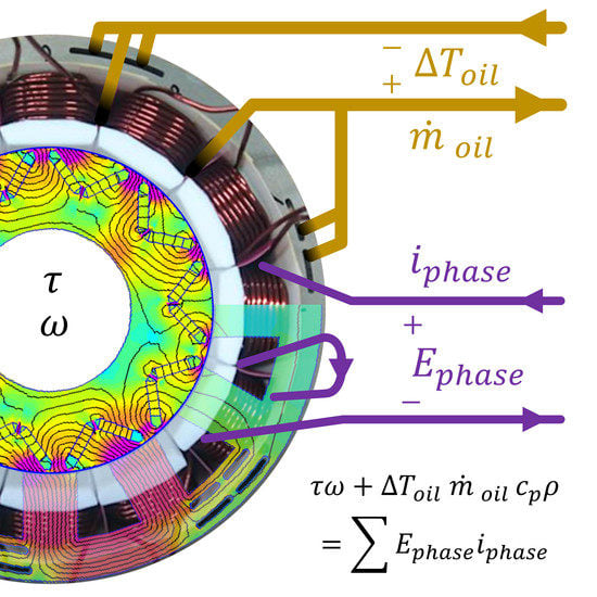
Table 6. The dSpace rack acts as the control hub of the dynamo setup. With the total setup, both electrical, mechanical and direct-loss power can be measured and displayed continuously and reference values can be set via a PC GUI. Oil and water temperatures are measured and converted to digital form with high resolution. The inlet-to-outlet temperature drop (
) of the coolant oil is established. Together with the oil mass flow (
), oil density (
kg/m
) and the oil specific heat capacity (
J/kg/K) the total loss heat transported out of the machine can be calculated as
More information on the oil used can be found in [
26]. The test machine and the oil system is thermally insulated towards the ambient in order to minimise thermal leakage and enable accurate calorimetric measurements. A glass fiber washer acts as a thermal insulator between the machine enclosure and the mounting frame. The coolant oil is heat exchanged with mass flow controlled tap water so that the inlet oil temperature to the machine is kept at 22 °C, in order to minimize leakage heat from the surroundings.
A three-leg IGBT based inverter, operating at 5 kHz SVM closed-loop current control is feeding the test machine at up to 600 . The dynamometer is operating at closed-loop speed control through a thyristor converter, feeding back power to the grid when the test machine is operating in motor mode.
6. Conclusions
This paper presents the design of a tooth coil winding PMSM machine for traction application, focusing on the electromagnetic design and performance verification. The solution adopted integrates stator cooling, both thorough the slot and the stator yoke. Original elements of this machine design are direct-oil cooling channels positioned in the stator yoke without negatively affecting the electromagnetic performance, and direct in-slot cooling by using a thermally conductive epoxy resin to create oil channels within the slot. It is shown that for the Q12p10 machine, the electromagnetic performance is negligibly affected when removing iron in the stator yoke for cooling channels if the position is carefully selected to the yoke area between the phase windings. The machine is designed such that it is possible to use a linear winding machine to pre-wind the coils on a bobbin, potentially leading to a reduced manufacturing cost for high volume production.
The adopted cooling solution enables a continuous copper current density of up to 25 A/mm
[
26]. This allows for a 75% higher output torque and power density comparing with a corresponding water-jacket-cooled machine. Inductance, torque and no-load back EMF are measured and compared with FEA results, showing very good agreement. Furthermore, the efficiency of the machine is validated in one operating point, using a calorimetric direct-loss measurement set up, matching with FEA within 0.9 units of percent. The peak efficiency according to FEA is a wide area above 95%, which is on par state-of-the-art automotive traction machines for higher power levels. The overall net power density (19 kW/l) is comparable with the current state-of-the-art traction machines on the market, even with higher power ratings, despite this machine being an early prototype. Further design improvements towards series production are also likely to bring the gross power density to very appealing levels by minimizing the volumetric overhead of coolant interfaces and connection terminals.


