Article

A Study of Heat Exchange Processes within the Channels of Disk Pulse Devices

1
Department of Energy, Ukrainian State University of Chemical Technology, Haharina Ave, 8, 49000 Dnipro, Dnipropetrovsk Oblast, Ukraine
2
Department of Mechanical Engineering and Mechanical Engineering, Ukrainian State University of Chemical Technology, Haharina Ave, 8, 49000 Dnipro, Dnipropetrovsk Oblast, Ukraine
3
Department of Development & Research, Dnipro University of Technology, UA-49027 Dnipro, Ukraine
4
Department of Materials Science, Ukrainian State University of Chemical Technology, Haharina Ave, 8, 49000 Dnipro, Dnipropetrovsk Oblast, Ukraine
5
LLC Soyuztekhnoprom Production Co., 49000 Dnipro, Dnipropetrovsk Oblast, Ukraine
6
Ukrainian-Turkmen Educational Center Erkin, UA-49027 Dnipro, Ukraine
7
Department of Energy Saving and Air Protection, Central Mining Institute, Plac Gwarków 1, 40-166 Katowice, Poland
8
Faculty of Science and Technology, Institute of Chemistry, University of Silesia, Szkolna 9, 40-006 Katowice, Poland
9
Experimental Mine Barbara, Central Mining Institute, Plac Gwarków 1, 40-166 Katowice, Poland
10
Scientific Research Institute of the Center of Renewable Energy and Energy Efficiency, Universidad Nacional de San Agustin de Arequipa, Arequipa PE-04000, Peru
11
Department of Thermal Machinery, Czestochowa University of Technology, Dabrowskiego 73, 42-200 Czestochowa, Poland
*
Author to whom correspondence should be addressed.
Energies 2020, 13(13), 3492; https://doi.org/10.3390/en13133492
Submission received: 3 June 2020 / Revised: 1 July 2020 / Accepted: 6 July 2020 / Published: 6 July 2020

Abstract

:
The effect of basic parameters of the channels of disk pulse devices on the heat exchange efficiency was studied both analytically and experimentally, especially in terms of pulse acting on the heat carrier. A methodology to determine the main parameters, namely the pressure and the temperature of the heat carrier as well as the pulse effect on the fluid, was proposed. The mathematical models of the effect of the structural and technological parameters of the channels in the disk pulse device on the heat exchange efficiency were developed. The models’ adequacy was proved based on a series of experimental studies involving devices with one-stage and multistage systems of pulsed heat carrier processing. This enabled the development, testing, and implementation of practical construction designs of pulse disk heat generators for decentralized heating of commercial and domestic buildings with one-stage and multistage systems of pulsed heat carrier processing. Taking into account the results of the mathematical modeling, the developed method of multistage pulse action was proved experimentally and implemented in regard to the structural design of a working chamber of the disk pulse heat generator. An efficient geometry of the working chamber of the disk pulse heat generator was specified for its further integration into the system of decentralized heat supply. One of the developed heat generators with the multistage pulse action on the heat carrier was integrated into the heating system of a greenhouse complex with a 0.86–0.9 efficiency coefficient.

1. Introduction

Production simplicity, commercial feasibility, equipment reliability, and reproducibility constitute essential factors in the development of environmentally friendly and efficient methods of energy generation [1,2,3]. Pulsed processing of process liquids is applied mainly as a method intensifying the hydrodynamic and mass-exchange processes. Currently, devices with pulse action on the liquids are used as heat energy generators [4]. The operating space of that type of aggregates has the form of a disk channel where one disk rotates and the other one remains immobile. The major part of the equipment has the following configuration of the operating space: centrifugal pumps, disk extruders, disk cavitators, and other devices [5,6]. The intensification of the gas dynamics and heat exchange processes within the disk pulse devices resulting from their operating space optimization is of great importance, especially in terms of improving the already available or developing new energy-efficient heat machines [4,7,8,9,10,11]. Studies dealing with the improvement of the energy efficiency of disk devices, which involve renewable and environmentally safe energy sources, represent one of the most important trends of the energy complex development [12,13]. Current research in the field of pulse device improvement is aimed at optimizing technological parameters at the expense of changes in the working chamber geometry [14,15,16]. Researchers are considerably interested in analyzing the hydrodynamics and heat exchange in pulse devices in relation to different operating modes.
Analytical descriptions of particular cases of the equation of compressible fluid motion in the disk channel in a vector form with numerous assumptions that cannot be applied for all device structures with pulse action on the liquid are presented in the literature [16,17,18].
Nikolsky et al. [19] developed a mathematical model, which allowed analysis of gas dynamics processes in the disk gaps of rotor pulse devices. This model contains two nonlinear differential equations relative to some functions f and ς , which help express the radial V r and tangential V φ velocity components, respectively. In this context, the function ς and tangential V φ velocity component correspondingly has nonlinear dependence along the disk gap. However, for calculation of the basic technological parameters, e.g., device efficiency and power, this nonlinearity does not introduce any considerable errors. Moreover, the solution of this system of differential equations was in the approximation of voluntary flow, i.e., without considering the pressure gradient along the radial coordinate. In some cases, the latter assumption may significantly distort the final results.
In this paper, the analytical heat exchange processes of the contacting phases in the liquid-solid body system for disk pulse devices with external power sources were studied. For this purpose, the analytical studies of the efficiency of the heat exchange processes in terms of pulse action were carried out. The determination of the optimal geometrical characteristics and energy efficiency of the disk pulse heat generator were investigated. In addition, the design of the experimental disk pulse device with an energy-efficient working chamber was proposed.

2. Materials and Methods

2.1. Analytical Studies of the Heat Exchange Process and Its Computer-Based Representation

In Figure 1, the analytical model of a disk pulse device to develop a mathematical model of the heat exchange is presented. The following assumptions and boundary conditions are specified:
The process in the disk pulse device is axially symmetrical; we neglect the changes in physical values along the angular coordinate (∂/∂φ = 0);
The process is of a steady-flow nature (time changes in physical values are insignificant ∂/∂t = 0);
Mass forces are neglected (ρ∙gi = 0);
The velocity component Vz is neglected as h << Rn;
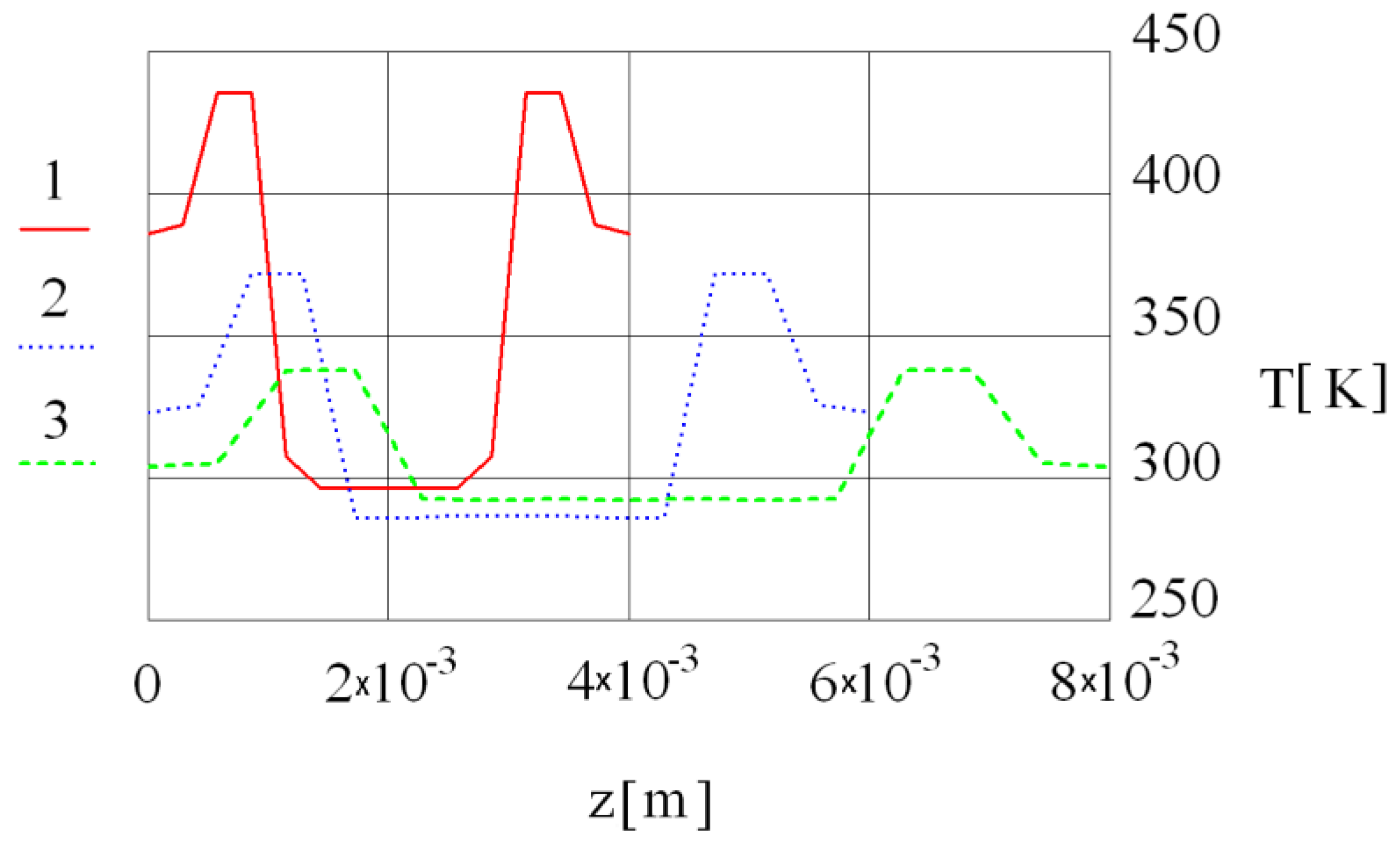
The temperature gradient at the expense of convective heat transfer along axis z is neglected; heat transfer along axis r is taken into consideration only in terms of heat convection.
The boundary temperature conditions along axis z are T z ( 0 , r ) = 0 , T z ( h , r ) = 0 . The initial conditions along axis r are T ( z , R 1 ) = T n , T r ( z , R 1 ) = 0 .
Analyzing the temperature field in the working chamber of a disk pulse device, on the basis of its design and nature of hydrodynamic flows, we take into consideration heat transfer by means of convective heat exchange along the radial axis r ; while heat transfer at the expense of heat conductivity, along axes z and r , and the changes in temperature along the angular axis are neglected. Then, the equation of heat energy balance will be expressed by the following ratio:
ρ · C p · V r ( z , r ) · T r = λ · ( 2 T z 2 + 2 T r 2 + 1 r · T r ) + F d ( z , r ) ,
where T is the temperature; λ is the coefficient of heat conductivity; Fd(z,r) is the function of dissipation; Vr(z,r) is the radial velocity component in projections on the corresponding axes; ρ is thee fluid density; and Cp is the liquid heat capacity under constant pressure.
The dissipation function makes it possible to define the heat power that is consumed in the working chamber of a disk pulse device. In order to do this, it is required to integrate the dissipation function in terms of the working zone volume.
In the case of Newtonian fluid, the dissipation function is as follows [20,21]:
F d ( r , z ) = 2 · η · [ ( V r , r ) 2 + 1 / 2 · ( V r / r ) 2 + ( V φ , r V φ / r ) 2 + ( V φ , z ) 2 + ( V r , z ) 2 ] ,
where Vφ(z,r) is the tangential velocity component in the projections on the corresponding axes; η is the coefficient of dynamic fluid viscosity.
The function determining the tangential velocity component is expressed by the following ratio [8,22]:
ς ( z ) = ω h · z ,
where ω is the angular velocity of disk rotation; h is the height of the disk gap; and z is the axial coordinate. The function determining the radial velocity component:
f(z) = Vr · r,
will be determined by taking into consideration the pressure gradient from the following equation [19]:
η · f ( z ) r + ρ · ( f ( z ) 2 r 3 + ω 2 h 2 · z 2 · r ) P r = 0 ,
where P r is the pressure gradient along the radial coordinate.
In terms of real operating modes of disk rotary-pulse devices, the complex of variables f ( z ) 2 r 3 in Equation (5) is far less than the expression ω 2 h 2 · z 2 · r . Based upon the latter note, Equation (5) may be represented in the form of a differential equation with separable variables:
d 2 f ( z ) d z 2 = ρ η · ω 2 h 2 · z 2 · r 2 + r η · P r .
It was assumed that the pressure gradient does not depend on the axial coordinate.
The solution of Equation (6) taking into consideration zero boundary conditions for function f(z) will be as follows:
f ( z ) = ρ η · ω 2 12 · r 2 · h · z · ( 1 z 3 h 3 ) r 2 · η · P r · h · z · ( 1 z h ) .
In the latter equation, the pressure gradient along the radial coordinate P r remains unknown; in order to find this gradient, we will apply the continuity equation:
Q 1 + Q 2 = Q 3 ,
where Q1 is the consumption of the fluid coming through the inlet branch; Q3 is the consumption of the fluid in the working chamber, kg/s; and Q2 is the consumption of the fluid within the disk gap determined according to the following formula:
Q 2 = 2 · π · 0 h f ( z ) d z .
Applying ratio (8) with the consideration of Equations (9) and (7):
P r = 3 10 · ρ · ω 2 · r + 6 · η π · ( Q 1 Q 3 ) r · h 3 ,
and having introduced (10) into (7), taking into account dependence (4), we will obtain the following expression:
V r ( z , r ) = ρ η · ω 2 · r · h · z · [ 1 12 · ( 1 z 3 h 3 ) 3 20 · ( 1 z h ) ]   3 · z π · r · h 2 · ( Q 1 Q 3 ) · ( 1 z h )

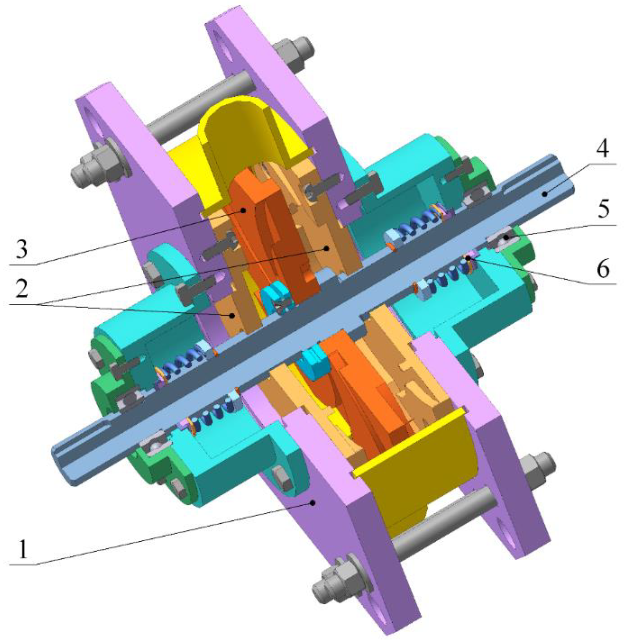
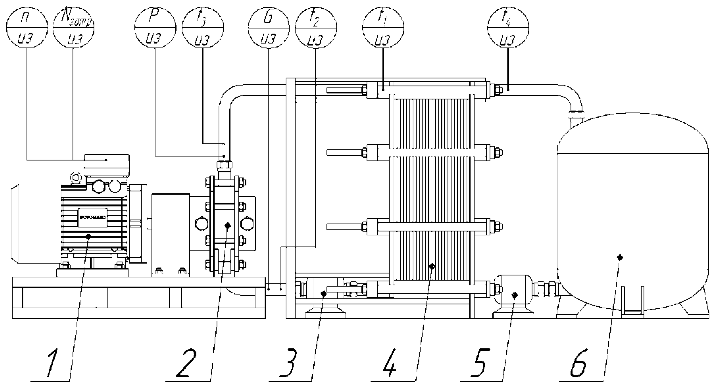
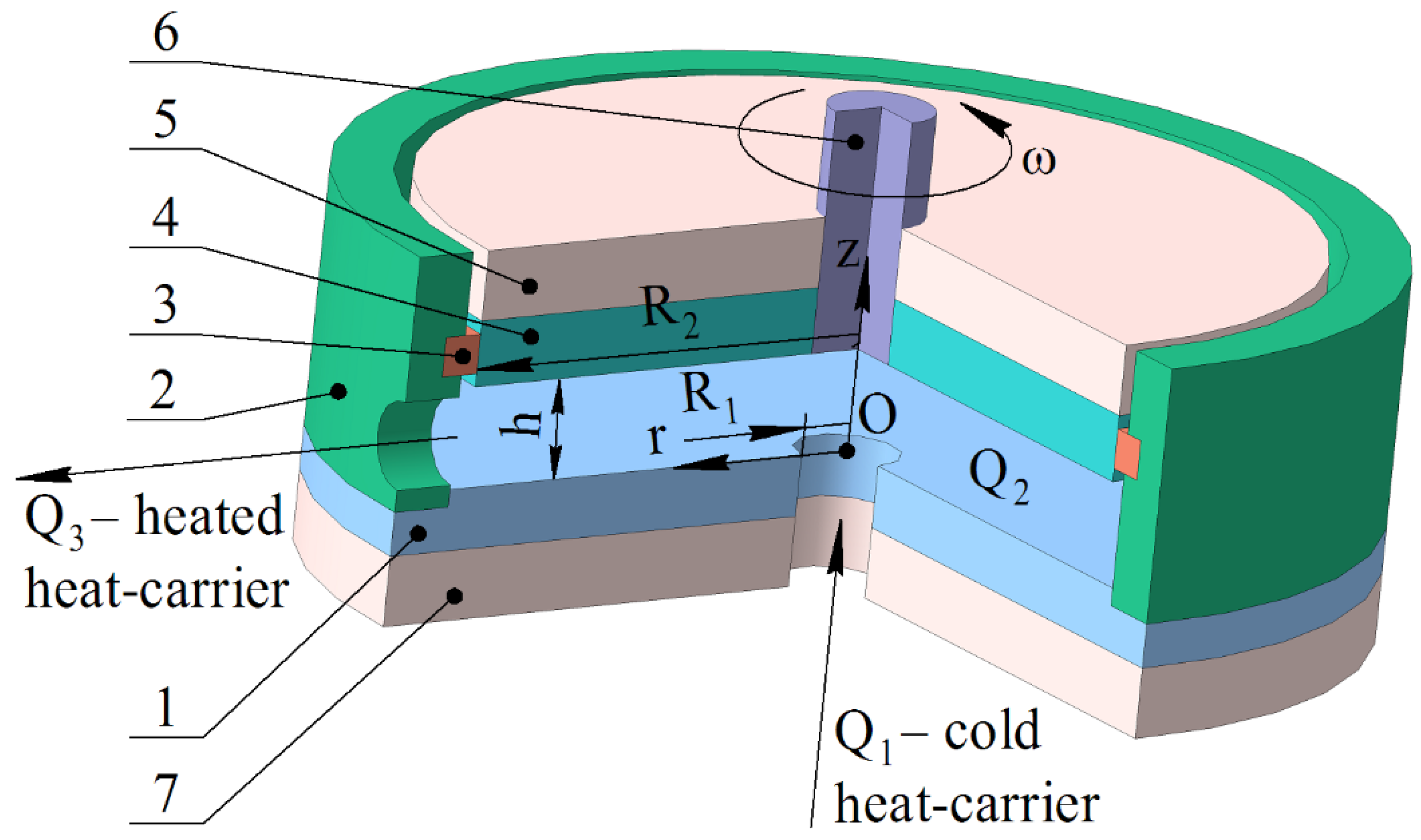
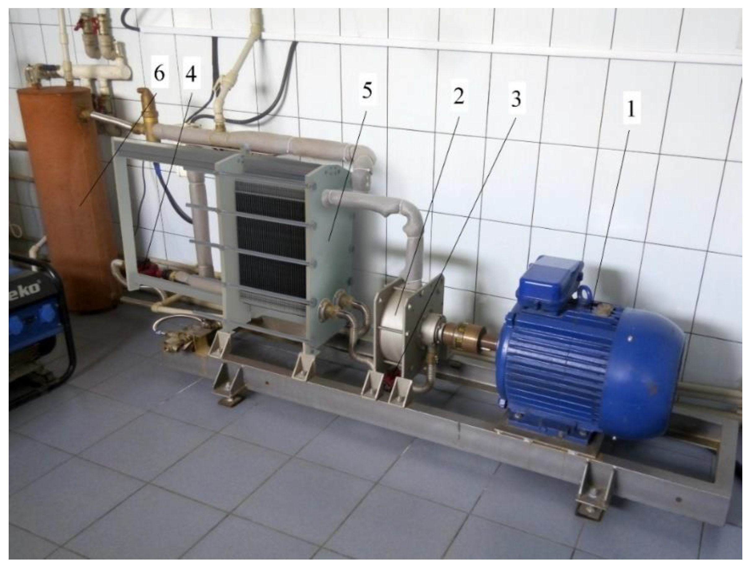
2.2. Structural Features of the Experimental Disk Pulse Heat Generator

In order to test the adequacy of the obtained mathematical models determining the effect of geometrical parameters of the channels of disk pulse devices on the efficiency of the heat exchange processes, experimental studies of the incompressible liquid within the disk pulse device have been carried out. To do this, a disk pulse heat generator (see Figure 2) was designed. The heat generator is represented as a working chamber with the changeable geometry of disk channels and the working disk diameter (rotor stage). It was used to mount the experimental stand equipped with the measuring system for testing (see Figure 3). The scheme of the experimental setup for testing the disk pulse heat generator is presented in Figure 4.
The following parameters were defined in the experiment:
-
t1, °C–temperature at the inlet to the heat exchanger (provided by an electronic contact MC–52,228 Mastercool thermometer);
-
t2, °C–temperature at the entrance to the disk pulse apparatus (provided by an electronic contact MC–52,228 Mastercool thermometer);
-
t3, °C–temperature at the outlet of the disk pulse apparatus (provided by an electronic contact MC – 52,228 Mastercool thermometer);
-
t4, °C–temperature at the exit of the heat exchanger (provided by an electronic contact MC–52,228 Mastercool thermometer);
-
P, Mpa–pressure in the working chamber of the disk heat generator (provided by a ДM 05100–01 M manometer, radial 0.6 MPa);
-
G, kg/s–flow rate of the heated medium (provided by an MTW-UA 25 vane counter for hot water);
-
n, min−1–engine speed (provided by a Guangdong T9Z-4 TMCON tachometer); and
-
Np.s., kW∙h– power spent (provided by an electric Nic 2102–02 M2B 5–60 A meter).
Changes in the number of the shaft-located disk rotors (working wheels) facilitated the process of one-stage and multistage cavitation. The system analysis of the research results was used to determine the most efficient geometry of the disk pulse heat generator for its further integration into the system of decentralized heat supply.

3. Results and Discussion

The radial velocity distribution within the disk gap in terms of different values of the disk gap is presented in Figure 5. In this context, the following values are taken as the basis: η = 5.471 · 10 4   Pa · s ; ω = 6.0   s 1 ; ρ = 988.1   kg / m 3 ; Q 1 = 8 · 10 5   m 3 / s ; Q 3 = 6 · 10 5   m 3 / s .
The dependences show that the maximum value of the radial velocity component corresponds to the disk gap height h = (5/7) × 10−3 m. Figure 6 presents the analytical graphs of the radial velocity component for different values of angular velocity ω and disk gap height h = 5 × 10⁻³ m, with the values of the parameters being in compliance with Figure 5.
The analysis of the dependences demonstrates that the maximum of the radial velocity component corresponds to disk channel height h = 4·10−3 m and angular velocity ω = 20 s−1. Taking into consideration the specified boundary conditions, the equation of heat energy balance (1) can be represented in the form of the following ratio:
ρ · C p · | V r c | · T r = λ · 2 T z 2 + F d ( z , r ) ,
where V r c is the average value of radial velocity within the disk gap. Having completed the corresponding transformations, see Equation (2), the obtained expression for the dissipation function is presented as follows:
F d ( r , z ) = 2 · η · [ [ K 1 · r · 9 · z · h 2 2 · h 3 10 · z 3 30 · h 3 3 π · h 2 · ( Q 1 Q 3 ) · ( 1 2 · z h ) ] 2 ] .
In Figure 7, the distribution of the dissipation function within the disk gap is presented.
The analysis of the dependences demonstrates that the maximum value of the dissipation function corresponds to h = 12 × 10−3 m.
In order to obtain the analytical solution of Equation (1), we use a transposition method (Fourier method) to write the following ratio:
T ( z , r ) = Θ ( z , r ) + Φ ( z , r ) ,
where Φ is the temperature representation and Θ is the heat flow representation. After corresponding re-grouping, substitution of (14) into (12), it results in the following expression:
| V r c | a · ( Θ r + Φ r ) = 2 Θ z 2 + F d λ .
In analytical studies, it is accepted that Φ z = 0   i f   z = h , so the factor of temperature change along the axis z 2 Φ z 2 = 0 , where a is the coefficient of temperature conductivity ( a = λ / ( ρ · C p ) ).
The heat flow function Θ is expressed by means of the following equation:
2 Θ z 2 | V r c | a · Θ r = 0 .
Taking into consideration the two latter expressions, the function Φ will be determined from the following ratio:
| V r c | a · Φ r = F d λ .
To solve Equation (16), we adopt the following boundary and initial conditions:
Θ z ( 0 , r ) = 0 Θ z ( h , r ) = 0 . Θ ( z , R 1 ) = T n
The following ratio is introduced:
Θ ( z , r ) = θ ( z ) · ξ ( r ) .
The substitution of (19) into (16) results in the following expression:
2 θ ( z ) z 2 · ξ ( r ) = | V r c | a · ξ ( r ) r · θ ( z ) .
It should be emphasized that in Equation (20), the left side depends upon coordinate z, while the right side depends upon coordinate r. The left and right parts are divided by θ ( z ) · ξ ( r ) and the separate differential equations are divided by two in ordinary derivatives, having equated them to some constant (e.g., minus λ2). Then, the following system of equations will be true:
d 2 θ ( z ) d z 2 + λ 2 · θ ( z ) = 0 ,
d ξ ( r ) d r + λ 2 · a | V r c | · ξ ( r ) = 0 .
The solution of Equations (21) and (22) results in the following:
θ ( z ) = C 1 · sin ( λ · z ) + C 2 · cos ( λ · z ) ,
ξ ( r ) = exp [ λ 2 · a | V r c | d r ] · C 3 .
Taking into account ratios (18) and (19), the constants of integration will have the following form:
0 = [ C 1 · λ · cos ( λ · 0 ) C 2 · λ · sin ( λ · 0 ) ] · exp [ λ 2 · a | V r c | · r ] · C 3 ,
0 = [ C 1 · λ · cos ( λ · h ) C 2 · λ · sin ( λ · h ) ] · exp [ λ 2 · a | V r c | · r ] · C 3 ,
T n = [ C 1 · sin ( λ · z ) + C 2 · cos ( λ · z ) ] · exp [ λ 2 · a | V r c | · R 1 ] · C 3 .
It results from expression (25) that the integration constant C1 is equal to zero. Equation (26) indicates the correctness of the ratio:
C 2 · sin ( λ · h ) = 0 .
The latter ratio is met under the condition that:
λ = n · π h ,
where n = 1,2,3…
Expression (27) is rewritten taking into consideration that C1 is equal to zero:
T n · exp [ λ 2 · a | V r c | · R 1 ] = C 23 · cos ( λ · z ) ,
where C 23 = C 2 · C 3 .
It follows from Equation (30) that, in a general case, value C23 depends upon coordinate z. To determine the constant of C23 integration, the Taylor cosine approximation is applied:
C 23 = 4 h · 0 h / 2 T n · exp [ λ 2 · a | V r c | · R 1 ] · cos ( n · π · z h ) · d z .
Hence:
C 23 = 4 · T n π · n = 1 , 3 , 5 exp [ n 2 · π 2 h 2 · a | V r c | · R 1 ] · 1 n · sin ( n · π 2 ) .
Based on ratio (32), the function Θ is determined from the following ratio:
Θ ( z , r ) = 4 · T n π · n = 1 , 3 , 5 exp [ β · ( r R 1 ) ] · 1 n · sin ( n · π 2 ) · cos ( n · π h · z ) ,
where β = n 2 · π 2 h 2 · a | V r c | , 2 Θ z 2 | V r c | a · Θ r = 0 .
To determine function Φ in Equation (17), the following is assumed:
1. Since the derivative of the heat flow function in Equation (16) changes along the radial coordinate, then the partial derivative of that function may be replaced with the ordinary one. Consequently, Equation (16) will have the form of a simple differential equation of the first order with separable variables.
2. Express the initial conditions to determine function Φ, taking into account ratios (12), (14), and (18), as:
Φ ( z , R 1 ) = T ( z , R 1 ) Θ ( z , R 1 ) .
Then, the solution of Equation (17) is as follows:
Φ ( z , r ) = 2 · η ρ · C p · | V r c | · [ f 1 2 ( z ) · r 3 / 3 2 · f 1 ( z ) · f 2 ( z ) · r + f 2 2 ( z ) / r ] + C 4
where f 1 ( z ) = K 1 · 9 · z · h 2 2 · h 3 10 · z 3 30 · h 3 ; and f 2 ( z ) = 3 π · h 2 · ( Q 1 Q 3 ) · ( 1 2 · z h ) .
Figure 8 represents the distribution of the temperature field within the disk gap.
Figure 9 shows the temperature distribution obtained for the same parameters as in Figure 5 within the disk gap outlet. In this context, the average temperature values within the gap outlet will be as follows: 324 K for curve 1, 308 K for curve 2, and 304 K for curve 3, respectively.
The temperature distribution demonstrates that in terms of h = 4·× 10−3 m, the average temperature within the disk gap outlet is 324 K. Along with the increasing dimensions of the disk gap, the average temperatures decrease to 304 K, corresponding to h = 8·× 10−3 m. This is due to the fact that while calculating the temperature field distribution within the disk gap outlet, only friction forces were taken into account. The cavitation component of the heat exchange process (energy emitted during the collapse of cavities) was neglected. According to the experiments, in the real process, the average temperature within the outlet of the cavitation chamber of a heat generator reaches 350 K for h = 8·× 10−3 m.
In Figure 10 a graph demonstrating heating the energy-efficient structures of one-stage and two-stage disk pulse heat generators is given.
According to the results of the processed studies, the efficiency of a one-stage disk heat generator (dependence 1) was η = 0.76. In order to increase the heat generator efficiency (i.e., energy conversion), a multistage pulse action upon the heat carrier was applied by means of locating a second disk on the rotor. The measured gap value c between the disks was within the range of (4 ÷ 12) × 10−3 m. According to the processed research data, the efficiency coefficient (dependence 2) was η = 0.84. Thus, taking into account the results of the mathematical modeling, proved experimentally and implemented in the design of the working chamber of the disk pulse heat generator, the method of the multistage pulse action has made it possible to increase its energy efficiency by 12%.
Based on the experimental studies, a heat-generating plant with two-stage pulse action on a heat carrier was developed and integrated into the heat supply system of a greenhouse complex with the area of more than 3000 m2.
The high energy efficiency of the developed heat generating device is explained by the following features of its structure:
  • The optimization of geometrical parameters of its working chamber based upon the results of mathematical modeling;
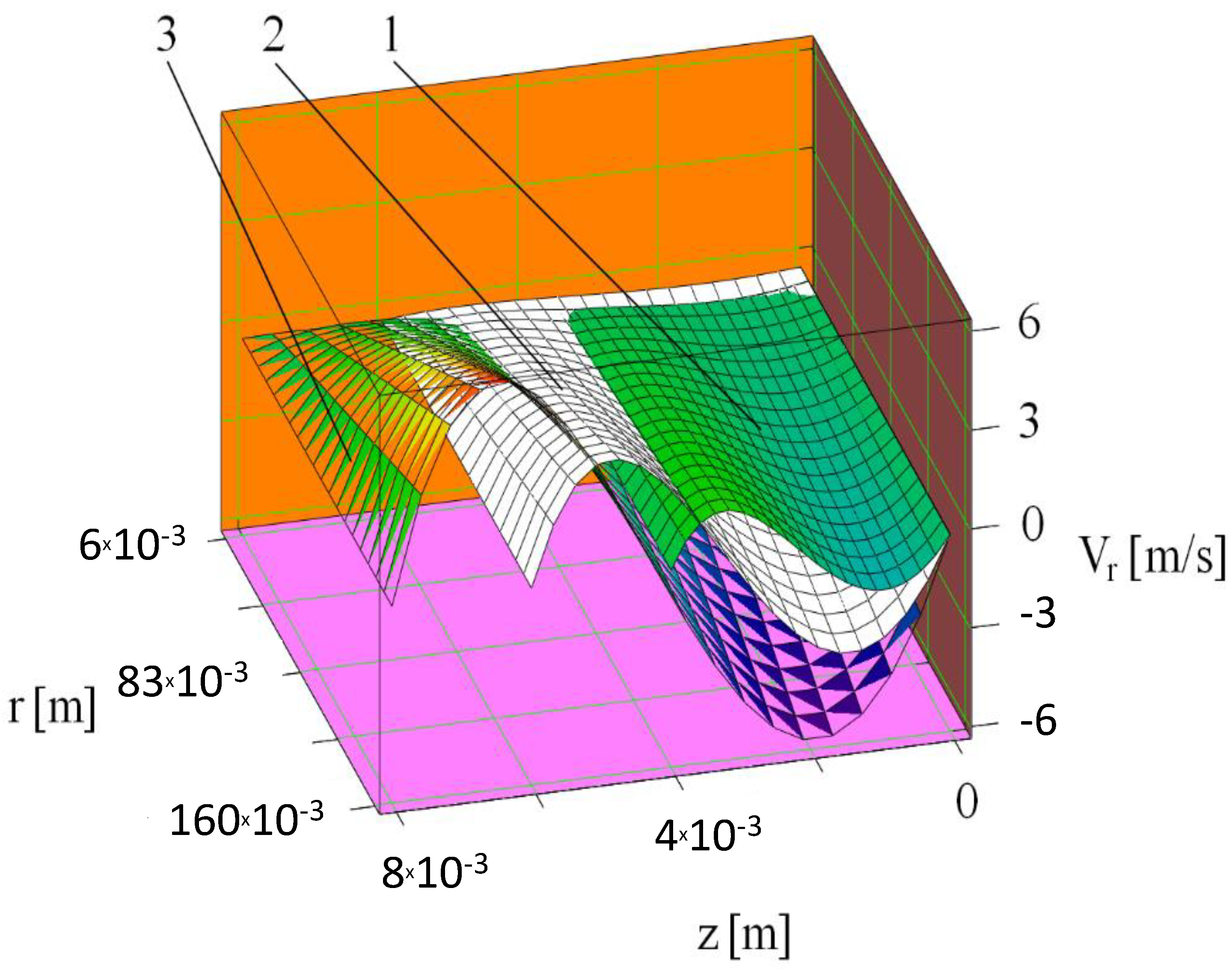
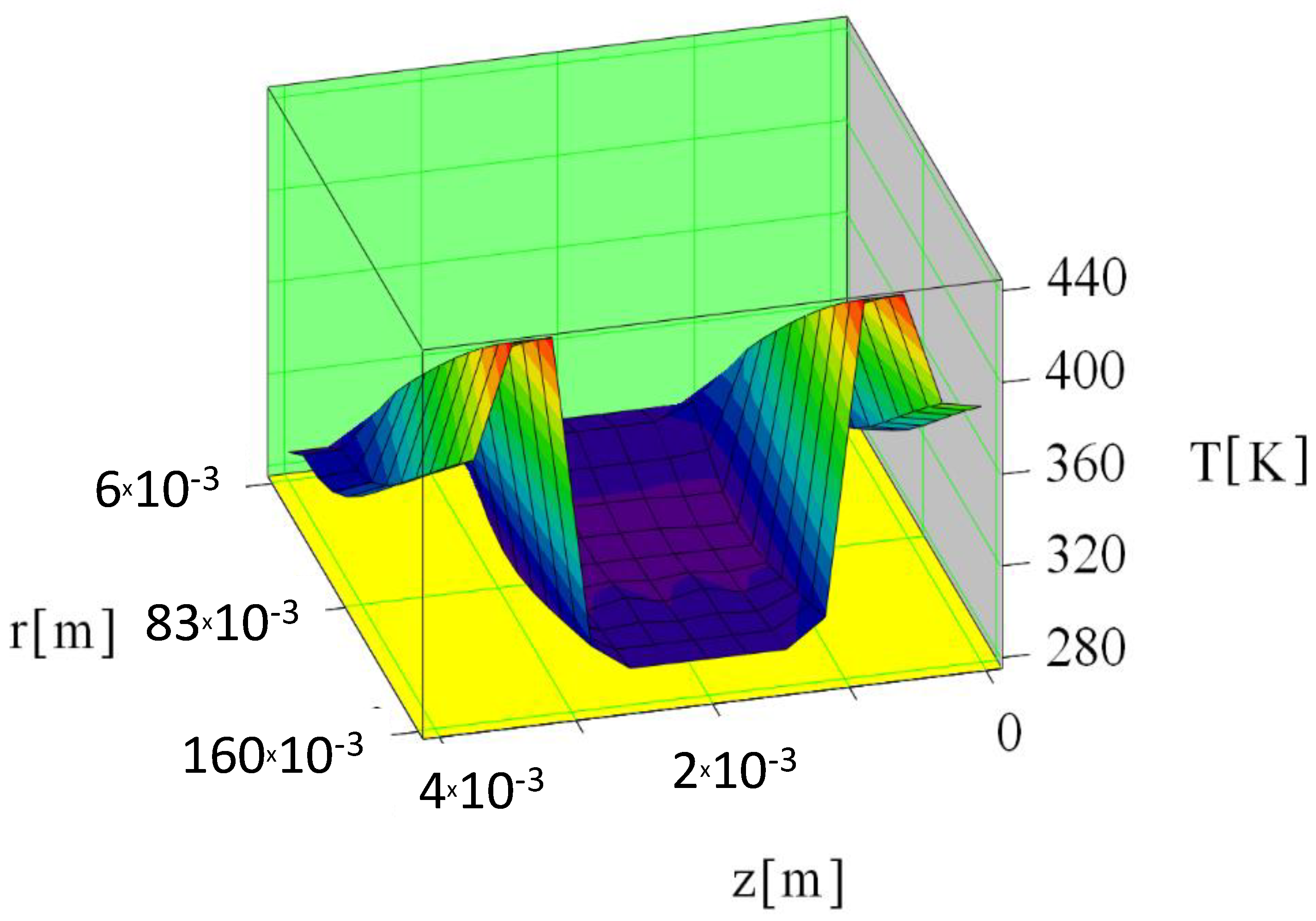
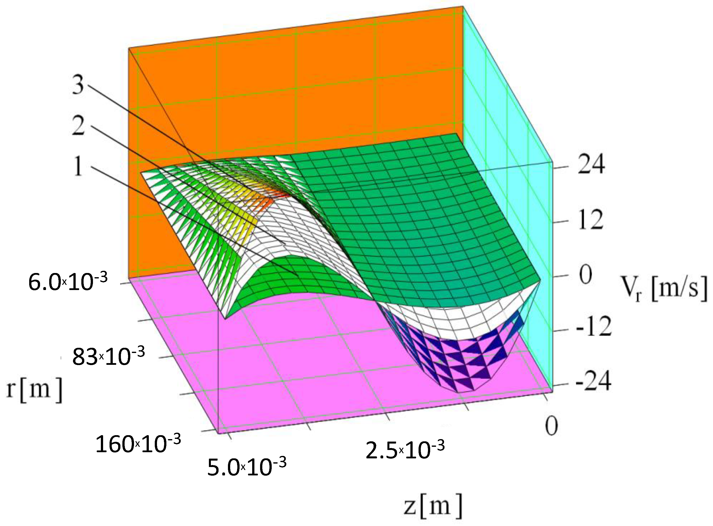
  • The optimization of the parameters’ hydrodynamics and heat-exchanging processes (velocity, pressure, temperature) inside the working chamber of the heat generator;
  • The application of a multistage system of pulse action on the heat carrier; and
  • The application of the automatic controls for the heating system involving the integrated heat generator in relation to pulse action on the heat carrier.
The obtained experimental energy efficiency operating parameters of the disk pulse heat generator were compared with the results of heat operation of pulse heat generators according to the literature sources [9,11,23,24,25,26,27]. The efficiency of the developed disk pulse heat generator is 17% higher (0.84 as compared to 0.706) than the efficiency of the structures of pulse disk heat generators with multistage pulse action described in the literature. While using the night tariff, the efficiency of the developed heat generator will reach the values of 95–98%.

4. Conclusions

The analysis of the distribution of the temperature field within the disk gap of the heat generator demonstrates that along with the increasing disk channel size h = (4/8) × 10−3 m, the maximum temperature in the disk gap within the phase boundary decreases from 430 to 335 K. In this context, the average temperature within the disk gap decreases from 324 to 304 K. While calculating the temperature field distribution within the output from the disk gap, only friction forces were taken into consideration. According to the experiments, during the real process, the average temperature within the output from the heat generator cavitation chamber can be up to 350 K for h = 8 × 10⁻³ m. This is associated with the additional energy generated during the collapse of cavities.
It was determined that the maximum efficiency value of a one-stage disk pulse heat generator is not more than η = 0.76. The application of a multistage pulse effect upon the heat carrier by locating a second disk on the rotor increases the efficiency up to η = 0.84.

Author Contributions

Conceptualization: V.N., I.K., R.D., A.S. (Adam Smoliński), O.A., V.Y., S.P. and L.T.; methodology: V.N., I.K., R.D., A.S. (Adam Smoliński), L.T., N.H., A.B., T.S., B.J.; validation: V.N., I.K., R.D., A.S. (Adam Smoliński), O.A., V.Y., S.P. and L.T.; formal analysis A.S. (Adam Smoliński), A.S. (Arkadiusz Szymanek), B.J., E.C.; investigation: V.N., I.K., E.C., R.D., A.S. (Adam Smoliński), O.A., V.Y., A.B. and N.H.; writing—original draft preparation: V.N., L.T., R.D., I.K., O.A. writing—review and editing: L.T., R.D., V.N., I.K.; visualization: V.N., I.K.; supervision: A.S. (Adam Smoliński). All authors have read and agreed to the published version of the manuscript.

Funding

This research received no external funding.

Conflicts of Interest

The authors declare no conflict of interest.

References

  1. Lago, L.I.; Ponta, F.L.; Chen, L. Advances and trends in hydrokinetic turbine systems. Energy Sustain. Dev. 2010, 14, 287–296. [Google Scholar] [CrossRef]
  2. Myers, L.E.; Bahaj, A.S. An experimental investigation simulating flow effects in first generation marine current energy converter arrays. Renew. Energy 2012, 37, 28–36. [Google Scholar] [CrossRef] [Green Version]
  3. Checko, J.; Urych, T.; Magdziarczyk, M.; Smolinski, A. Resource Assessment and Numerical Modeling of CBM Extraction in the Upper Silesian Coal Basin, Poland. Energies 2020, 13, 2153. [Google Scholar] [CrossRef]
  4. Nikolsky, V.; Oliynyk, O.; Ved, V.; Svietkina, O.; Pugach, A.; Shvachka, A. Development and investigation of energy efficient unified equipment for energy technological manufacturers. East. Eur. J. Enterp. Technol. 2018, 3, 59–65. [Google Scholar] [CrossRef] [Green Version]
  5. Meng, Q.C.; Zhang, Z.H.; Liu, J.B. Numerical Calculation for Subsonic Compressible Supercavitating Flow over Disk-Cavitator. Appl. Mech. Mater. 2010, 34–35, 737–742. [Google Scholar] [CrossRef]
  6. Aben, E.; Markenbayev, Z.H.; Khairullaev, N.; Myrzakhmetov, S.; Aben, K.H. Study of change in the leaching solution activity after treatment with a cavitator. Min. Miner. Depos. 2019, 13, 114–120. [Google Scholar] [CrossRef] [Green Version]
  7. Hamid, U.; Rauf, A.; Ahmed, U.; Selim Arif Sher Shah, M.; Ahmad, N. Techno-economic assessment of process integration models for boosting hydrogen production potential from coal and natural gas feedstocks. Fuel 2020, 266, 117111. [Google Scholar] [CrossRef]
  8. Pivnyak, G.; Dychkovskyi, R.; Bobyliov, O.; Cabana, C.E.; Smoliński, A. Mathematical and Geomechanical Model in Physical and Chemical Processes of Underground Coal Gasification. Solid State Phenom. 2018, 277, 1–16. [Google Scholar] [CrossRef]
  9. Smoliński, A.; Howaniec, N. Chemometric modelling of experimental data on co-gasification of bituminous coal and biomass to hydrogen-rich gas. Waste Biomass Valorization 2017, 8, 1577–1586. [Google Scholar] [CrossRef] [Green Version]
  10. Iwaszenko, S.; Howaniec, N.; Smoliński, A. Study of numerical models of underground coal gasification. Energy 2019, 166, 972–978. [Google Scholar] [CrossRef]
  11. Dychkovskyi, R.O. Determination of the rock subsidence spacing in the well underground coal gasification. Naukovyi Visnyk Natsionalnoho Hirnychoho Universytetu 2015, 6, 30–36. [Google Scholar]
  12. Basu, R. Evaluation of some renewable energy technologies. Min. Miner. Depos. 2017, 11, 29–37. [Google Scholar] [CrossRef] [Green Version]
  13. Goncharenko, L.; Ryzhakova, A.; Sedova, N.; Efimov, I.; Akulinin, F. Survey of the world practice of implementing energy-efficient technologies in terms of mining enterprises. Razrab. Mestorozhdenii 2019, 13, 63–71. [Google Scholar] [CrossRef]
  14. Dellicompagni, P.; Franco, J.; Heim, D.; Wieprzkowicz, A. Numerical modeling of phase change materials using simusol software. Appl. Therm. Eng. 2020, 170, 114772. [Google Scholar] [CrossRef]
  15. Park, J.T.; Cutbirth, J.M.; Brewer, W.H. Hydrodynamic Performance of the Large Cavitation Channel (LCC). In Proceedings of the ASME/JSME 2003 4th Joint Fluids Summer Engineering Conference, Honolulu, HI, USA, 6–10 July 2003; American Society of Mechanical Engineers: New York, NY, USA, 2003; pp. 87–100. [Google Scholar]
  16. Lin, J. Modelling hydrodynamic processes in tidal stream energy extraction. J. Hydrodyn. Ser. B 2016, 28, 1058–1064. [Google Scholar]
  17. Dealy, J.M.; Wissbrun, K.F. Melt Rheology and Its Role in Plastics Processing: Theory and Applications; Springer Science & Business Media: Berlin/Heidelberg, Germany, 2012; p. 244. [Google Scholar]
  18. Sarycheva, L. Using GMDH in ecological and socio-economical monitoring problems. Syst. Anal. Model. Simul. 2003, 43, 1409–1414. [Google Scholar] [CrossRef]
  19. Nikolsky, V.; Kuzyayev, I.; Alieksandrov, O.; Ved, V.; Pugach, A.; Yaris, V.; Ptitsyn, S.; Lopatin, V. Analytical and experimental studies into the processes of hydrodynamics and heat exchange in the channels of disk pulse devices. East. Eur. J. Enterp. Technol. 2019, 4, 15–23. [Google Scholar] [CrossRef]
  20. Bellout, H.; Bloom, F. Incompressible Bipolar and Non-Newtonian Viscous Fluid Flow; Springer: Berlin/Heidelberg, Germany, 2014. [Google Scholar] [CrossRef]
  21. Böhme, G. Principles of continuum mechanics. In Non-Newtonian Fluid Mechanics; North-Holland Series in Applied Mathematics and Mechanics; Elsevier: Amsterdam, The Netherlands, 1987; pp. 1–43. [Google Scholar]
  22. Chernai, A.V.; Sobolev, V.V.; Chernai, V.A.; Ilyushin, M.A.; Dlugashek, A. Laser ignition of explosive compositions based on di-(3-hydrazino-4-amino-1,2,3-triazole)-copper(II) perchlorate. Combust. Explos. Shock Waves 2003, 39, 335–339. [Google Scholar] [CrossRef]
  23. Golovchenko, A. Automated Monitoring of Physical Processes of Formation of Burden Material Surface and Gas Flow in Blast Furnace. Solid State Phenom. 2018, 277, 54–65. [Google Scholar] [CrossRef]
  24. Falshtynskyi, V.S.; Dychkovskyi, R.O.; Saik, P.B.; Lozynskyi, V.H.; Cabana, E.C. Formation of thermal fields by the energy-chemical complex of coal gasification. Naukovyi Visnyk Natsionalnoho Hirnychoho Universytetu 2017, 5, 36–42. [Google Scholar]
  25. Bondarenko, V.; Tabachenko, M.; Wachowicz, J. Possibility of production complex of sufficient gasses in Ukraine. New Tech. Technol. Min. Proc. Sch. Undergr. Min. 2010, 3, 113–119. [Google Scholar] [CrossRef]
  26. Golovchenko, A.; Dychkovskyi, R.; Pazynich, Y.; Edgar, C.C.; Howaniec, N.; Jura, B.; Smolinski, A. Some aspects of the control for the radial distribution of burden material and gas flow in the blast furnace. Energies 2020, 13, 923. [Google Scholar] [CrossRef] [Green Version]
  27. Chećko, J.; Urych, T.; Magdziarczyk, M.; Smoliński, A. Research on the processes of injecting CO2 into coal seams with CH4 recovery using horizontal wells. Energies 2020, 13, 416. [Google Scholar] [CrossRef] [Green Version]
Figure 1. Computational scheme to develop mathematical models: 1–immobile disk; 2–casing 3–sealing component; 4–rotating disk; 5, 7–heat-insulating plates; 6–shaft.
Energies 13 03492 g001
Figure 2. Structural scheme of the developed disk pulse heat generator: 1–rotor case; 2–stator disks; 3–working disk (rotor stage); 4–rotor shaft; 5–bearing; 6–sealing.
Energies 13 03492 g002
Figure 3. Experimental stand to test the operating efficiency of the disk pulse heat generator: 1–electric engine; 2–chamber of the disk pulse heat generator; 3, 4–pumps; 5–plate-type heat exchanger; 6–accumulating tank.
Energies 13 03492 g003
Figure 4. Experimental setup for testing the efficiency of the disk pulse heat generator: 1–electric engine N = 15 kW∙h; rotor speed n = 3000 rpm; 2–chamber of the disk pulse heat generator; 3, 5–centrifugal pump; 4–plate heat exchanger Alfa Laval; 6–storage capacity.
Energies 13 03492 g004
Figure 5. Graphs of the radial velocity component for different values of disk gap heights: 1–h = 4·× 10−3 m; 2–h = 6·× 10−3 m; 3–h = 8·× 10−3 m.
Energies 13 03492 g005
Figure 6. Graphs of the radial velocity component for different values of angular velocity within the disk gap h = 5·× 10−3 m: 1–ω = 8 s−1; 2–ω = 14 s−1; 3–ω = 20 s−1.
Energies 13 03492 g006
Figure 7. Graph of the dissipation function Fd.
Energies 13 03492 g007
Figure 8. Graph of the temperature distribution within the disk gap with parameters corresponding to Figure 2 (h = 4 × 10⁻³ m).
Energies 13 03492 g008
Figure 9. The temperature distribution within the disk gap outlet: 1–h = 4 × 10⁻³ m; 2–h = 6·× 10−3 m; 3–h = 8·× 10−3 m.
Energies 13 03492 g009
Figure 10. Graph of the heat carrier heating within the one-stage–1 and two-stage–2 disk pulse heat generator.
Energies 13 03492 g010

