1. Introduction
Microgrids are one of the promising solutions for smarter and more efficient energy operations. The recent growth of small-scale energy generations as well as the rapid progress of power electronics applications has increased the attention toward microgrids control and management issues in recent years. Moreover, concerns about the reduction of power plants immense contribution of greenhouse gasses (GHG) have shed light on microgrids importance and the role they could play to reduce the release of toxic gases to the environment [
1,
2]. Another aspect of its importance is the recent shift toward more transportation electrification, which require more electric vehicles (EVs) charging structures on the distribution system. However, the rise of microgrids with its dependence on intermittence renewable energy sources (RES) as well as stochastic EVs activities have underlined voltage stability and frequency control problems that must be carefully addressed for more safe and resilient operation. Specifically, uncoordinated large-scale integration of renewables sources, as well as rapid adoption of EVs with highly stochastic charging and discharging activities, will lead to detrimental consequences such as voltage collapse, power quality problems, frequency, and stability oscillations, to name a few. Therefore, proper control and operation of microgrids is required to allow coordinated control mechanisms while taking into consideration the heterogeneous mix of parameters corresponding to different attached power sources [
3]. Research on microgrids operation and control has been widely considered in the literature. The authors of reference [
4] analyzed various architecture, management, and control in the microgrid paradigm, while the authors of reference [
5] presented a survey on various research that considered the integration of distributed energy resources with microgrids in different countries. Reference [
6] investigated a decentralized energy control scheme for autonomous poly-generation microgrid topology to achieve proper management in case of malfunctioning of downstream parts. The authors of reference [
7] examined a game theory, multi-agent-based microgrid energy management system with the coordination of the decentralized agents are employed via Fuzzy Cognitive Map (FCM). Besides, the authors of reference [
8] presented a valuable review study on various hierarchical control schemes of microgrids on the primary, secondary, and tertiary control layers that aim to reduce the overall operation cost while improving the controllability and the reliability of microgrids.
Photovoltaic solar (PV) is one of the most advanced and reliable forms of renewable energy sources. However, the utilization of PV systems has yet to overcome many operational issues to be considered a thoroughly reliable and dispatchable source of energy for microgrids. The most critical issue with the consideration of PV systems is its intermittency throughout the day. Such shortages in the PV system’s supply of energy could be compromised with increasing the level of energy transfer to the microgrid through EVs discharging, which is one of the main aspects this paper is investigating. The work on PV systems is one of the widely considered research topics in the past decades. Optimization problems have been well-developed to investigate and verify the control of PV systems taking into consideration its stochastic nature such as in [
9,
10]. The authors of reference [
9] investigated the effect of changing cell’s temperature and solar irradiance on the design of various DC-DC converter topologies which are widely used in PV systems. The authors of reference [
10] proposed a new topology scheme for a photovoltaic dc/dc converter which can drastically enhance the efficiency of a PV system by assessing the PV’s module characteristics. The authors of reference [
11] proposed an algorithm that offers dynamic distributed energy resources control that includes PV systems, small-scale wind turbines, controllable loads, and energy storage devices. Furthermore, studies on PV systems covered a wide range of applications, where reference [
12] proposed an energy management strategy with PV-powered desalination station that is coupled with DC microgrids.
Another side of consideration in this work is the relative impact of EVs integration on the hybrid microgrid operation. Reference [
13] presents a linearization methodology to model real-time EVs activities on residential feeders based on the concept of Kirchhoff laws, nodal analysis, and modularity index. EVs offer high potentials to serve as mobile backup storage devices that can provide grid support to enhance its reliability as a means of smart grid application [
14]. Reference [
15] provides a Matlab-based Monte Carlo Simulation code that allows the incorporation of distributed energy resources (i.e., EVs) to assess the distribution network’s reliability. Additionally, studies have covered the potentials of EVs in relevant frequency regulation and control. The authors of reference [
16] proposed an intelligent aggregator that synchronizes the charging and discharging activities of a group of EVs in order to regulate frequency by compensating for any potential power deficiency. Similarly, the authors of reference [
17] proposed a real-time dynamic decision-making framework based on Markov Decision Process (MDP) to allow intelligent frequency regulation by energy support from EVs. Reference [
18] developed a multivariable generalized predictive controller to enable load frequency control in a standalone microgrid with V2G integration. The controller aims to allow sufficient energy exchange without causing frequency deficiency, considering possible load disturbances. Furthermore, the recent progressive policies that aim to reduce GHG emissions from the transportation sector will result in a mass acquisition of EVs in the next few years [
19], especially in regions where utilization of EV is expected to have a significant reduction of GHG emissions as a result of their weather and energy grid mixes [
20]. Such rapid adoption of EVs on a large scale without proper coordination can result in phase imbalance, equipment fallout and degradation, increase active and reactive power losses, among many problems [
21]. Therefore, careful consideration needs to be given to overcome the problems that may arise due to the intermittency and stochastic nature of the energy sources on the hybrid microgrids.
In this work, an energy management and control strategy is developed to overcome the fluctuations of the voltage and frequency levels due to the presence of intermittent renewable energy sources and electric vehicle charging structure in hybrid microgrids. Furthermore, a hybridization algorithm of the Particle Swarm Optimization (PSO) and Applied Artificial Physics (APO) is utilized to tune the vector-decoupled control parameters of the interlinking converters to ameliorate the performance of the hybrid microgrid to achieve better resiliency and operation. Our proposed strategy highlights guaranteed stability of operation in the DC part of the microgrid while efficiently coordinate with the AC part during severe operating conditions such as high pulsed demands and islanding operation. The proposed algorithm is tested via a hardware-in-the-loop testbed at the Florida International University to for results verification. The results embolden the validity of our proposed strategy and hybridized algorithm to establish secure and safe active and reactive power exchange between the two sides of the hybrid microgrid without invoking an operational violation.
This paper is organized as follows:
Section 2 shows in detail the system description and corresponding illustration of the modelling and control of the bidirectional converter,
Section 3 presents the hybrid algorithm deployed in our work to provide the converter with optimized control parameters,
Section 4 presents the experimental modelling and results of the proposed control mechanism, with
Section 5 providing concluding remarks.
2. System’s Description, Modeling, and Control
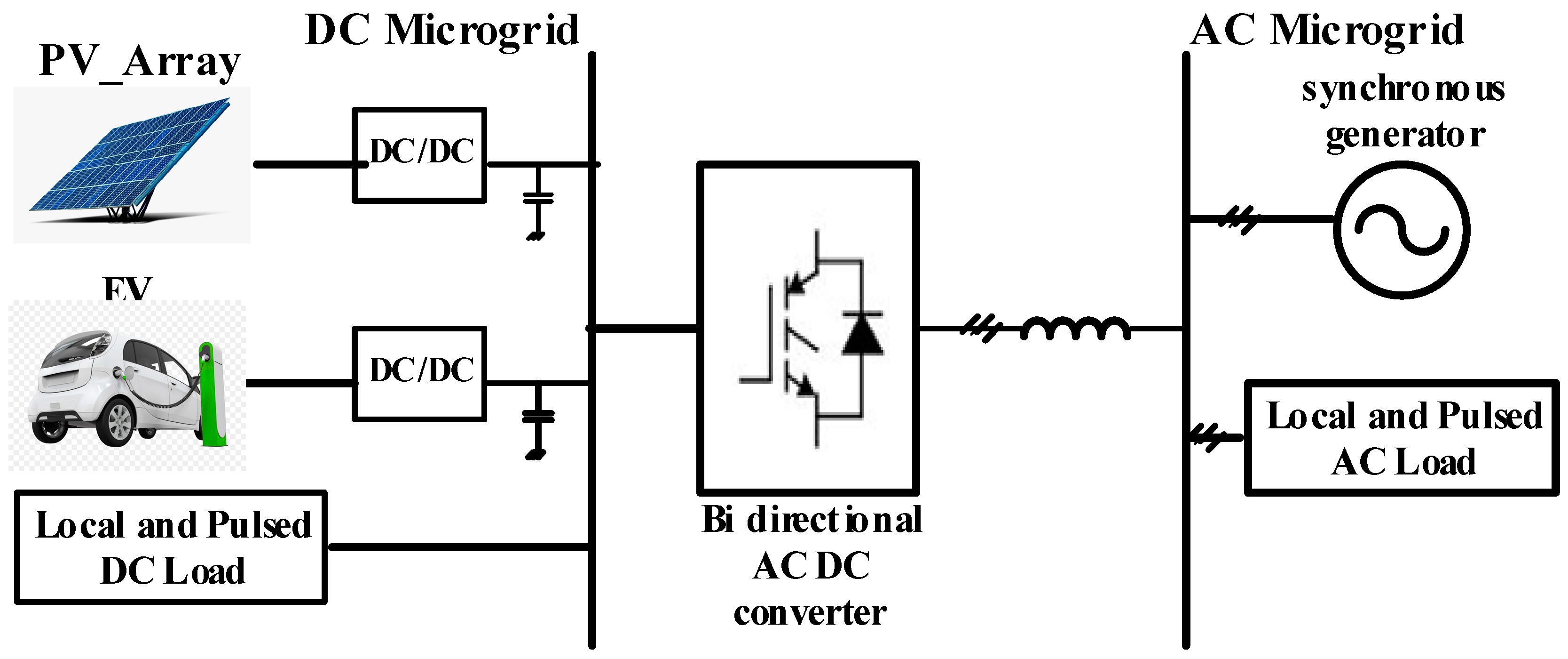
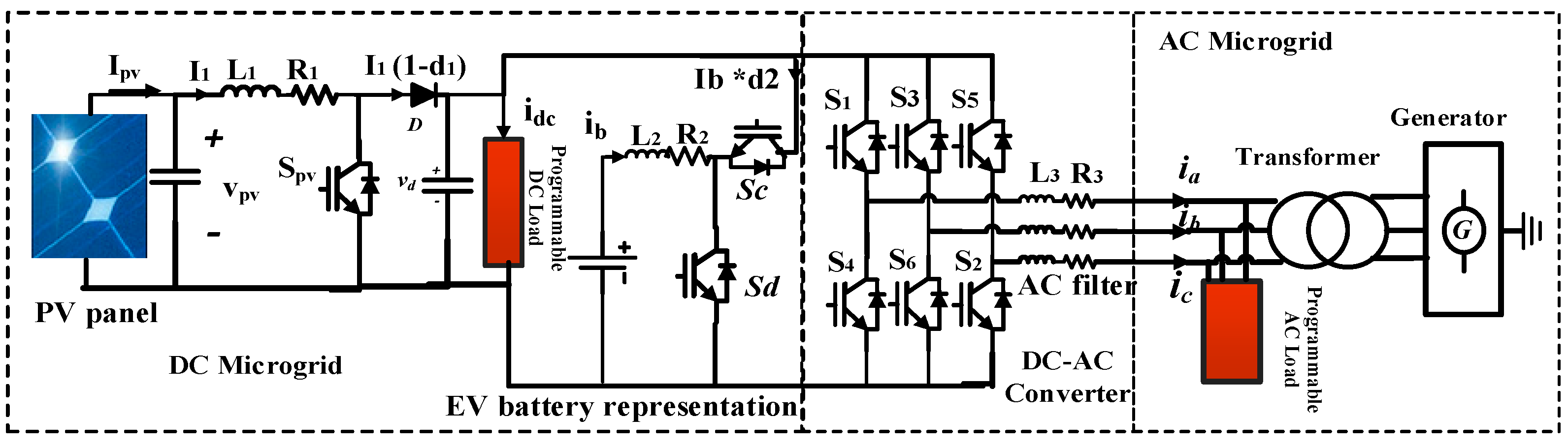
Figure 1 presents the system of study in this work which is implemented in hardware at the Energy Systems Research Laboratory group (ESRL) of the Florida International University (FIU). More information about the hardware testbed and its connections can be found in the previously published literature [
22,
23,
24]. The hybrid microgrid at the testbed incorporates different harvested AC and DC sources that are integrated through interfaced power converters. Both sides are interlinked via a bidirectional converter, with the DC part contains PV systems, electric vehicles parking structure, and local and pulsed DC loads. On the other hand, the AC part of the microgrid is supplied with a synchronous generator as well as the typical load demands. During islanding operation, the microgrid is isolated and maintain its supply to local loads via both AC and DC sources. The microgrid is designed such that it can autonomously satisfy the energy demands without interruption under any circumstances. Two DC-to-DC boost converters are used in this work to link the DC components to the bidirectional power converter, as illustrated in
Figure 1.
Table 1 presents the parameters of the interlinking converter used in this work.
Where Rs, Rcout, and Rcin are the resistance of the voltage source located at the DC side, resistances of the output and input capacitor of the power converter, while Cout and Cin are the values of the output and input capacitors.
2.1. PV System Model and Interface
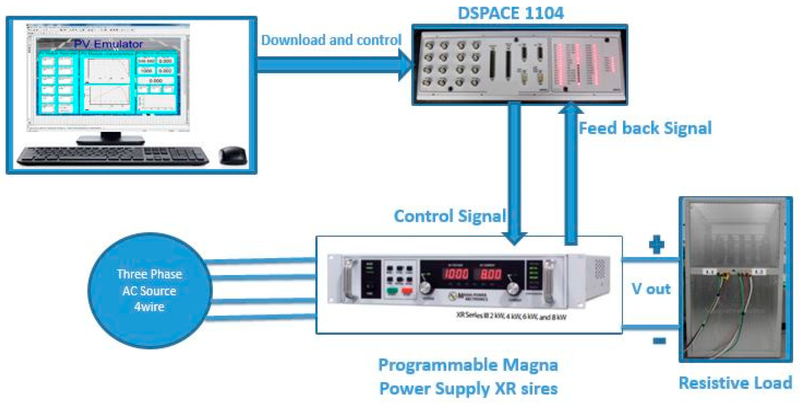
The PV system is modeled with a PV emulator that has a maximum capacity of 6 kW and can imitate a real-time PV system with different characteristics and under various operational conditions such as during temperature and irradiance changes. The PV emulator is constructed to utilize real-time algorithms that represent the PV array’s mathematical models to generate reference power output from a programmable DC supply. Specifically, the PV models are established in Simulink and resembled in real-time operation via dSPACE following a graphic user interface (GUI). Accordingly, the emulator is then tested with real-time execution of the PV model considering various dynamic operational and steady-state conditions.
Figure 2 presents the configuration of the laboratory PV emulator, which was first introduced by the authors in previous work [
23].
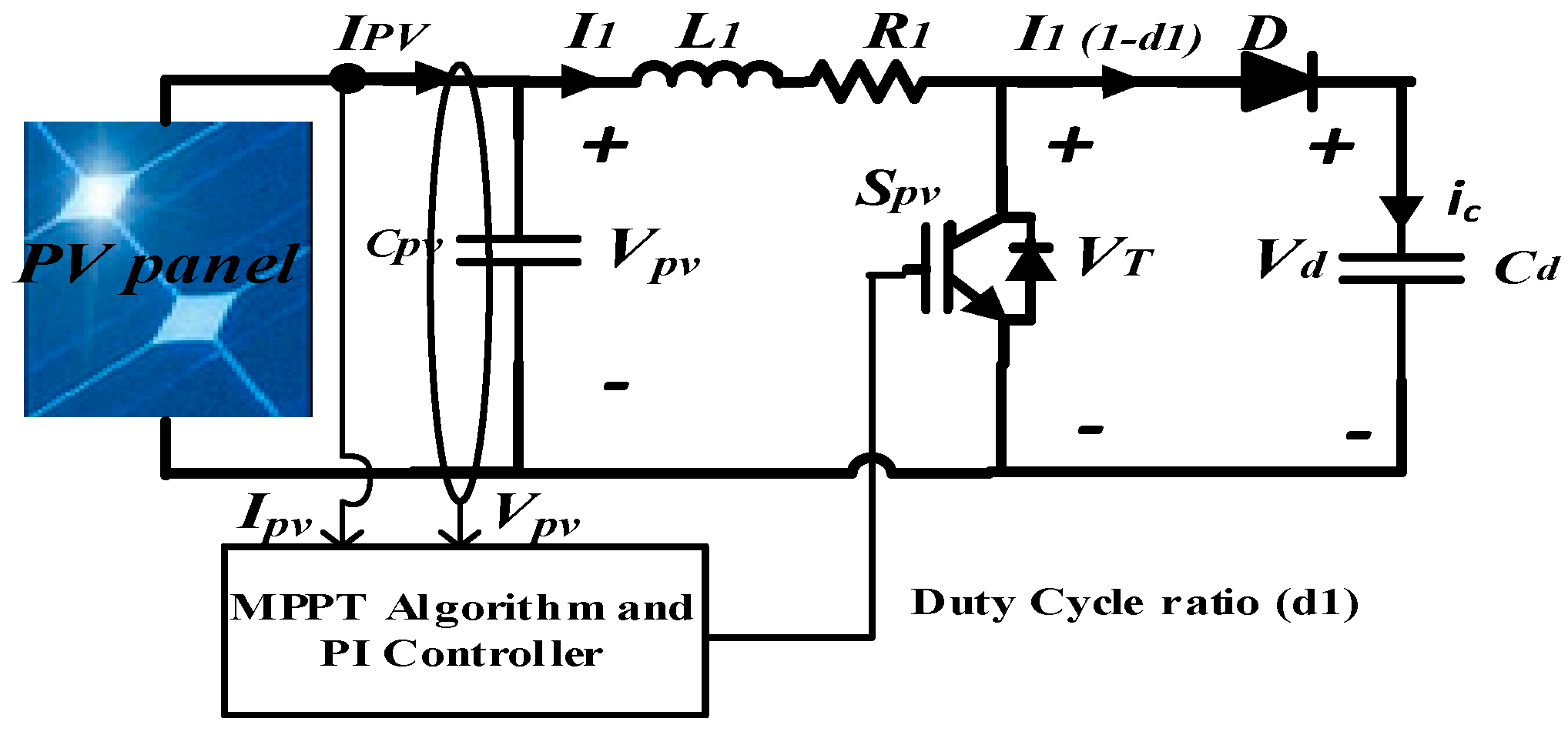
Figure 3 shows a schematic illustration of the PV system connectivity with the boost converters for accurate integration with the microgrid’s DC side. It is worth mentioning that the type of PV module in this work is the SPR-305-WHT PV system manufactured commercially by SunPower and can generate 305 watts as an output power per module with an efficiency of 18.9%. The current-voltage (IV)characteristic of the PV system could be represented by a single diode model as it provides accuracy and simplicity [
25]. The current output of the PV arrays can be found by
where
is the output current of the PV array,
is the voltage reference which is established based on the perturbation and observation (P&O) algorithm that takes into consideration the temperature and solar irradiation levels,
is the internal PV current,
is the diode’s reverse saturation current,
is the parallel leakage resistance,
is the series resistance,
A represents the ideality factor of the solar cell, while
q is the charge of the electron that is assumed to be 1.6 × 10
−19 C, and
KB is the Boltzmann constant which is 1.3806488 × 10
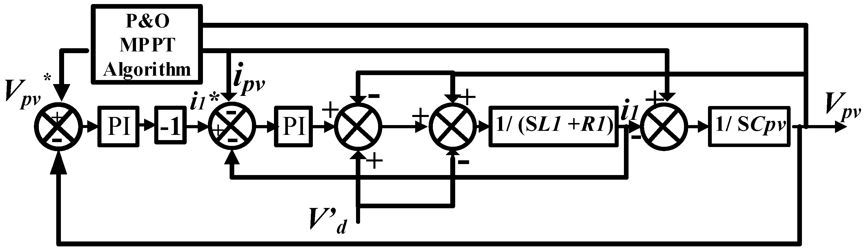
−23 J/K. The DC-to-DC boost converter is used to step up the voltage level of the PV arrays to the voltage level of the microgrid’s DC side when needed while ensure maximum power extraction based on the concept of maximum power point tracking (MPPT). Specifically, the P&O algorithm [
26,
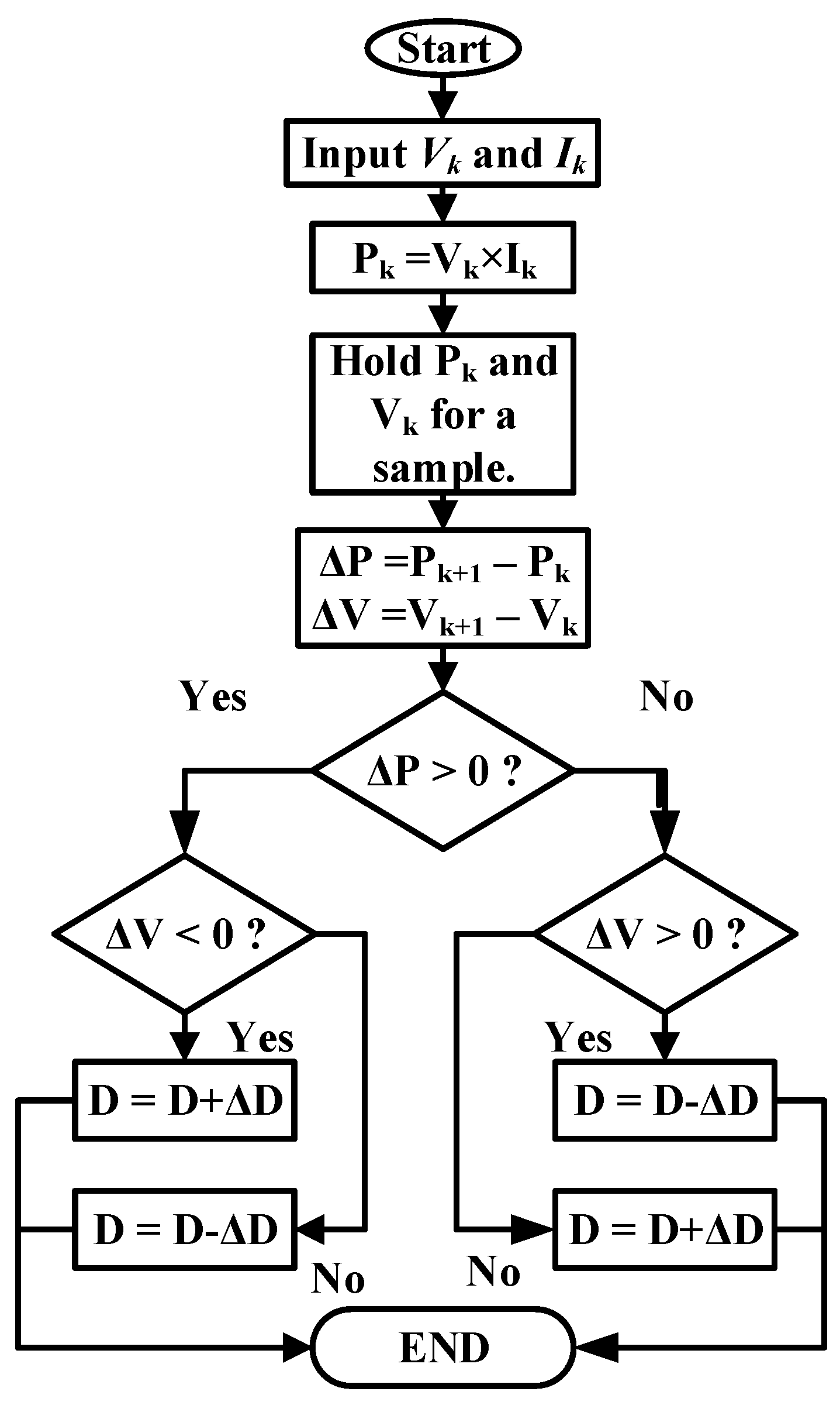
27] is utilized in this work. This algorithm mainly depends on perturbing the voltage level of the PV panels by small magnitude (ΔV) and accordingly observing the change of power level (ΔP) to optimize the tracking of maximum power transfer from the arrays to take into consideration potential temperature variability during the day.
The main contribution from utilizing the (P&O) algorithm in our work is to aim for zero difference of power received from the PV arrays in two successive iterations, denoted ΔP. This is accomplished by measuring the level of power at each iteration based on the PV output current so that the power level at the
kth iteration is recorded,
Pk, and
P(k+1) for the following iteration. The DC-to-DC boost converter adjusts the power output of the PV system by either decreasing in the case of a negative ΔP or increasing it for the case of a positive ΔP. Once ΔP approaches zero, the PV system is said to be reaching its maximum power point (MPP). The process is updated iteratively throughout the operation hours to ensure maximum power production from the PV arrays.
Figure 4 illustrates the described iteration process, while
Figure 5 shows the implementation of the control process for the DC-to-DC converter in our work.
The control mechanism for the DC-to-DC boost converter is achieved based on the following formulas
where
and
are bidrectional converter inductance and resistance,
is the current corresponding to the duty-cycle ratio
of the switch
.
is the voltage across the switch, while
is the voltage reference across capacitance
and is determined following the utilization of the P&O algorithm based on the temperature and solar irradiation levels of PV arrays, as mentioned earlier. It should be noted that the control process is based on the dual-loop control mechanism. The inner current loop assists in the improvisation of the dynamic response, while the outer voltage loop keep tracks with the reference voltage levels given zero steady-state error.
2.2. Electric Vehicles (EVs) Battery Converter Model and Control
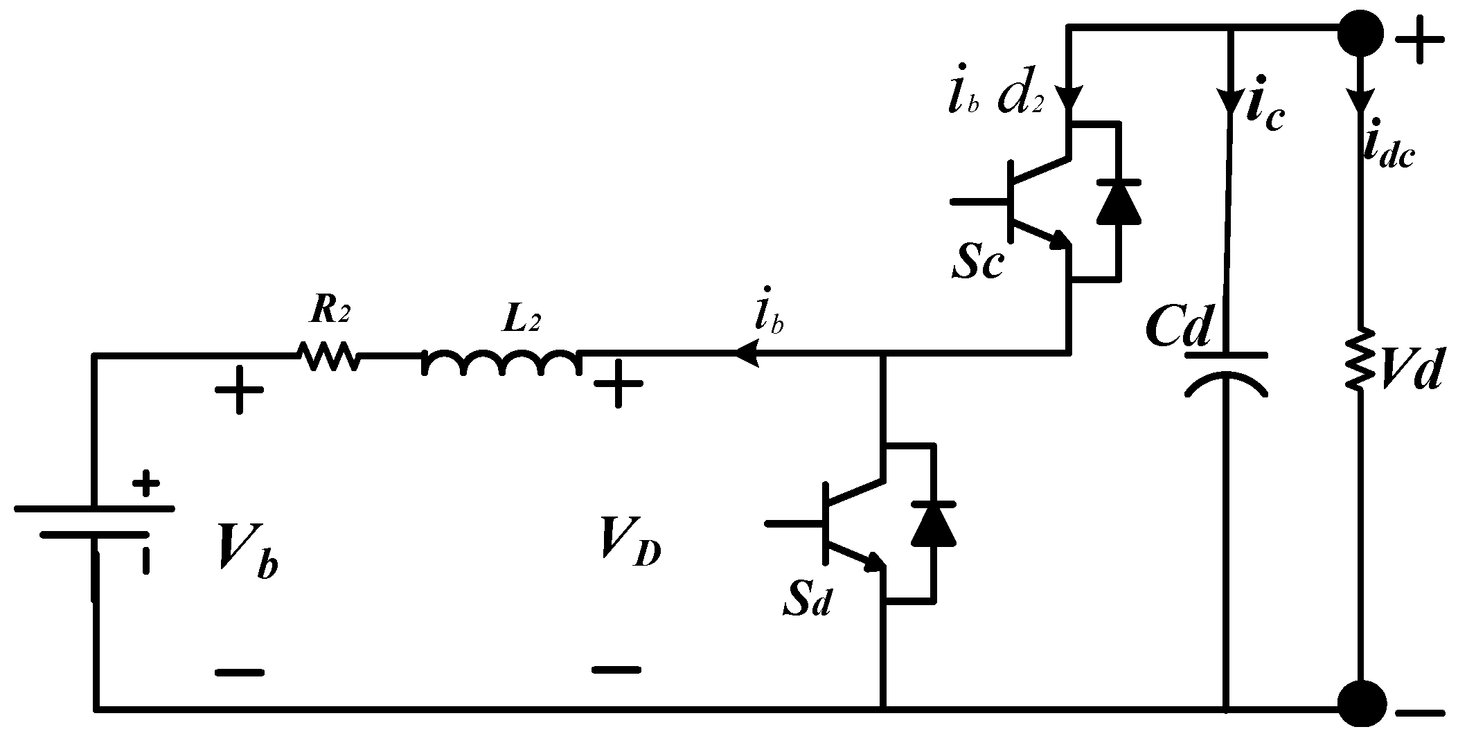
The developed scheme for the electric vehicle charging converter is shown in
Figure 6. The converter topology is a composed of a bidirectional DC-to-DC converter, with the EV is connected to the low-voltage side of the converter. The high-voltage side of the converter is directly connected with the microgrid DC bus. The converter is composed of two switches, Sc and Sd, each with its own operation mode and time. Specifically, switch Sc is on when the converter operates at the buck mode for charging activity during power transfer from the DC Bus to the EV’s battery.
Conversely, switch Sd is on when the converter operates at the boost mode during the discharging process of the EV during power transfer from the EV’s battery back to the DC bus. The control mechanism for the EV’s battery converter is shown in
Figure 6, and is mathematically illustrated as follows
where
and
are the DC side’s voltage and current,
is the current corresponding to the AC side of the hybrid microgrid,
is the EV battery’s voltage and current,
is the bidirectional converter capacitance for boost mode,
are bidirectional converter inductance and resistance. It should be noted that the main task of the bidirectional DC-DC converter connected to the EVs charging structure is to regulate the DC bus voltage. To achieve this purpose, a dual-loop control is utilized to assist in providing a stable DC link voltage. Specifically, the external voltage-controlled loop establishes a reference charging current as a signal for the internal current-controlled loop. The difference between the reference and measured bus voltage serves as an input signal to the PI controller. This difference is used to measure the reference charging current since the internal current-controlled loop compares this estimated current-signal with that one of the referenced current flowing inside the converter. The produced output of this loop control serves as an input signal for a second PI controller for further optimization of the inner controller.
The EVs battery current
is calculated based on Equation (5), while the duty cycle is estimated by Equations (6) and (7). The discharging current can be calculated as follows
That is to say, if the voltage of the microgrid’s DC bus is higher than the desired reference voltage signal, then the outer voltage control generates a negative reference current signal for the inner current-controlled loop. The generated signal current is used to adjust the correspondent duty cycle in order to influence the converter to operate in a buck mode only and suspend any discharging activity at the moment. On the other hand, if the voltage of the microgrid’s DC bus is lower than the desired reference voltage signal, then the outer voltage control generates a positive reference current signal to regulate the current flow during the discharging process. As a result, an additional amount of energy is incurred and injected to the DC bus while improving the voltage profile at the moment. It is worth mentioning that the physical reference for the voltage source of the DC bus is 400 V.
2.3. Bidirectional DC-to-AC Converter Model and Control
In hybrid microgrids, managing robust frequency and voltage levels is challenging, especially during forced islanding operation where the AC side loses its connection to the grid’s main slack bus. Typically, a hybrid microgrid owns synchronous generators that can manage load variations and maintain energy supply, even during islanded operation. However, high demands connected to the hybrid microgrid may lead to severe consequences such as frequency deficiency and potential voltage collapse. As a result, the bidirectional DC-AC converter’s main task is to enable strict frequency and voltage regulation considering severe operational scenarios [
28]. We consider this controller type to ensure a smooth power exchange between the DC and AC sides of the microgrid. The mathematical representation of the DC-AC converter model is illustrated as follows:
Considering D-Q coordinates, Equation (9) could be rewritten as follows
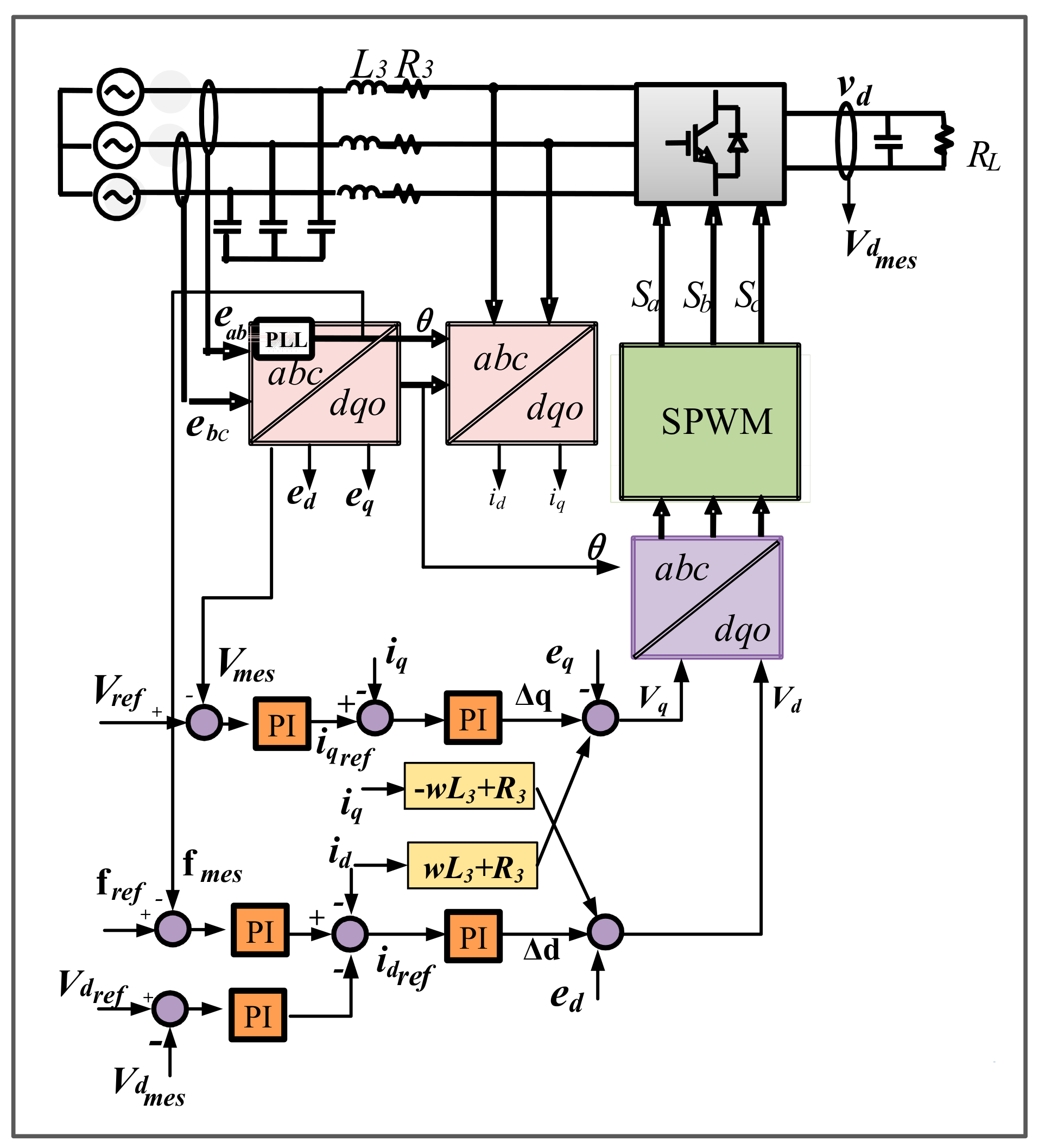
The control mechanism of the bidirectional DC-AC converter utilized in our work is shown in
Figure 7, where two-loop controllers, for both real and reactive power, are applied. The overall goal is to allow proper and intelligent control of both frequency and voltage levels at the hybrid microgrid. For frequency control, the difference between the measured frequency signals from that of the obtained reference frequency is established. The result is subtracted from the difference error between the measured and referenced DC voltage level, as described in part B of this section. The obtained value serves as an input signal to the PI controller, which initiates the current reference value, Id. Likewise, another control loop is deployed to achieve voltage stability employing optimized reactive power flow in the hybrid microgrid. This is made in the same manner as frequency control, where the difference between the measured and referenced voltage levels is calculated to produce a signal that serves as input to another PI controller to generate the Iq reference current. In the next section, we present a metaheuristic methodology based on the hybridization of Particle Swarm Optimization (PSO) and Artificial Applied Physics (APO) to tune the vector-decoupled control parameters illustrated in
Figure 7 optimally.
3. Control Parameters Design Using Hybrid Artificial Physics Optimization-Particle Swarm Optimization (APOPSO) Algorithm
The central concept of applying our hybridization of PSO and APO is to integrate their individual strengths to establish an optimization algorithm that exhibits both the dominant global search abilities of the APO and efficient local exploration performance of the PSO while enhancing its convergence rate. In this work, the hybrid algorithm is utilized to optimize the vector-decoupled control parameters of the bidirectional converter to ensure efficient energy management driven by optimized variables while reducing the trial–error method described in
Section 2. In a previous study, the authors developed an optimal reactive power dispatch study based on the hybrid APOPSO [
29].
3.1. Artificial Physics Optimization (APO)
APO is a physics-based metaheuristic technique that is based on the idea of a gravitational metaphor that enables forces to produce attractiveness or repulsiveness movements on the articles that resemble the solutions of the optimization problem [
29,
30,
31]. These movements represent the searching criteria for estimating the values of local and global optima. Furthermore, this is accomplished since the APO treats the examined parameters as physical objects that exhibit a mass with relative position and velocity. The mathematical description of the APO is as follows
When
f(x) € [−
,
], then; arctan [−
f(
)] € [
,
], and
€
with
where Equations (11) and (12) is mapped into the interval (0,1) via basic transformation function. Therefore, the mass functions of the APO is described as follows
where
f (
) is the objective function corresponding to the position of the best-achieved value for the individual solution, which in this work resembles the best-obtained control parameter. On the other hand,
f (
) refers to the value of the worst particular solution reported during the searching process. Both are represented as follows:
where
S is a set that is composed of
N population of controlling parameters. A velocity vector is produced once each particle’s mass is identified, with the level of exerted force influencing the change in velocities in an iterative manner. The amount of exerted force on each particle
i (solution) can be found as follows
and
where
is the
kth force exerted on particle
i via another particle
j in their corresponding dimensions;
and
are the
kth dimensional coordinates of the swarm particles
i and
j;
is the distance between the two measured coordinates.
Sgn(r) represents the signum function, whereas
G(r) depicts the gravitational factor that follows the changes on
iteratively, both represented mathematically as follows
In a thorough manner, the total force applied on all particles (control parameters of study) can be modeled as:
One crucial aspect to consider when deploying the APO to solve an optimization problem is the understanding of its particles’ motion paradigm in the solution space. Specifically, the measured force could be used to estimate the velocity of the moving particles and therefore find in an iterative fashion their respected positions in the solution space. Such motion paradigm is set in a two- or three-dimensional space and is modeled as follows:
and represent the kth city and distance components corresponding to particle i during an iteration t, while is a uniformly distributed random variable within the interval [0, 1] and w is a user-defined inertia weight that is updated iteratively and usually assume a value between the interval 0.1 to 0.99. Furthermore, the inertia weight is a good indication of the level of performance of the APO algorithm, with higher values of w indicates greater velocity changes. It should be noted that at each iteration, each particle identifies the information of its nearby particles (solutions) which emphasizes the great search strategy of the APO. Once an iteration is performed, all the particles’ relative positions are identified and consequently the objective fitness function adjusts to the newly obtained positions. A stopping criterion is enabled once a pre-determined number of iterations are reached without a significant difference in the obtained best particle position.
3.2. The Particle Swarm Optimization (PSO)
Considered one of the most popular metaheuristic techniques, PSO is a bio-inspired, population-driven algorithm first presented by Kennedy in [
32]. PSO advances based on evolutionary computations with a sample of preliminary randomized solutions at the first iteration, updated iteratively to establish local and global optima values. The obtained solutions are deemed particles that fly in the solution space with a determined velocity from preceding iterations. It should be noted that the obtained velocity and position values of each solution set are updated iteratively as follows:
(t) and (t) are both vector representations of velocity and position in the solution space for particle i, whereas Pbest and gbest stand for the best individual and global obtained solutions, respectively. The popularity of PSO as a well-established and referred metaheuristic algorithm is attributed to its efficient searching strategy along with prematurely convergence rates without the requisite of finding a local optimum in first place.
3.3. The Hybridization of APO and PSO to Optimize the Vector-Decoupled Control Parameters
The hybridization of APO and PSO is to establish in this work to take advantage of their individual strengths that lead to an overall improvement in the optimization process. Specifically, such integration utilizes the high efficiency of global search of the APO with the strong local exploratory search of the PSO while significantly enhancing its convergence rate. In this paper, the two algorithms are integrated following a low-level heterogeneous routine. As a consequence, the velocity and positions equations are modified as follows:
This proposed hybridization allows parallel search within a set of population which leads to avoidance of getting trapped in local optima. The control parameters to be optimized are
Kp_f,
Ki_f,
Kp_vdc,
Ki_vac, Kp_m, Ki_vdc,
Ki_m, and
Kp_vac. Following the microgrid’s dynamic simulation, the hybrid APOPSO algorithm evaluates the integral absolute values of both the frequency (∆
f) and the RMS voltage (∆
Vrms) deviation levels corresponding to the AC part of the microgrid. In this paper, two fitness functions are applied to the hybrid algorithm to properly estimate the self-tuning of the gains of the PI controller. The output of the fitness functions is used to control the power-sharing levels of the bidirectional converter, as follows
where
e(t) represents the level of the errors,
y(t)* the desired value to be obtained and
y(t) is the actual measured value per each iteration, while
and
represent penalty factors to enforce the voltage and frequency levels to be within the desired limits.
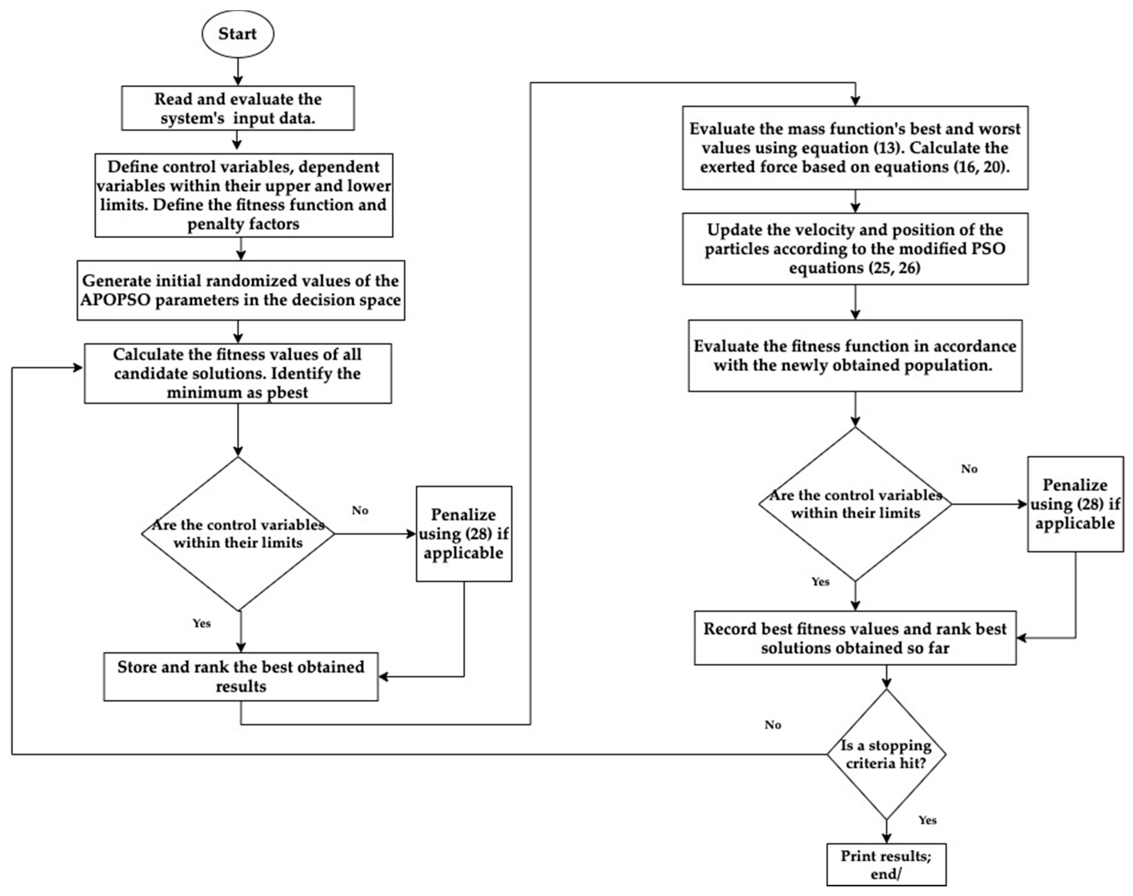
Figure 8 shows the flowchart of the proposed hybrid algorithm to optimize our control parameters.
The purpose of utilizing this search strategy is to ensure safe and optimal sharing of the power between the two sides of the hybrid microgrid in terms of providing the bidirectional controller with optimized vector-decoupled control parameters to achieve ideal converter’s operation and ensure operation within system’s limits which are defined in our study not to exceed
5% of the frequency, and
8% of the base voltage levels. The results of applying this hybrid algorithm is shown in
Table 2 with the produced optimal parameters to ensure optimized damping performance.
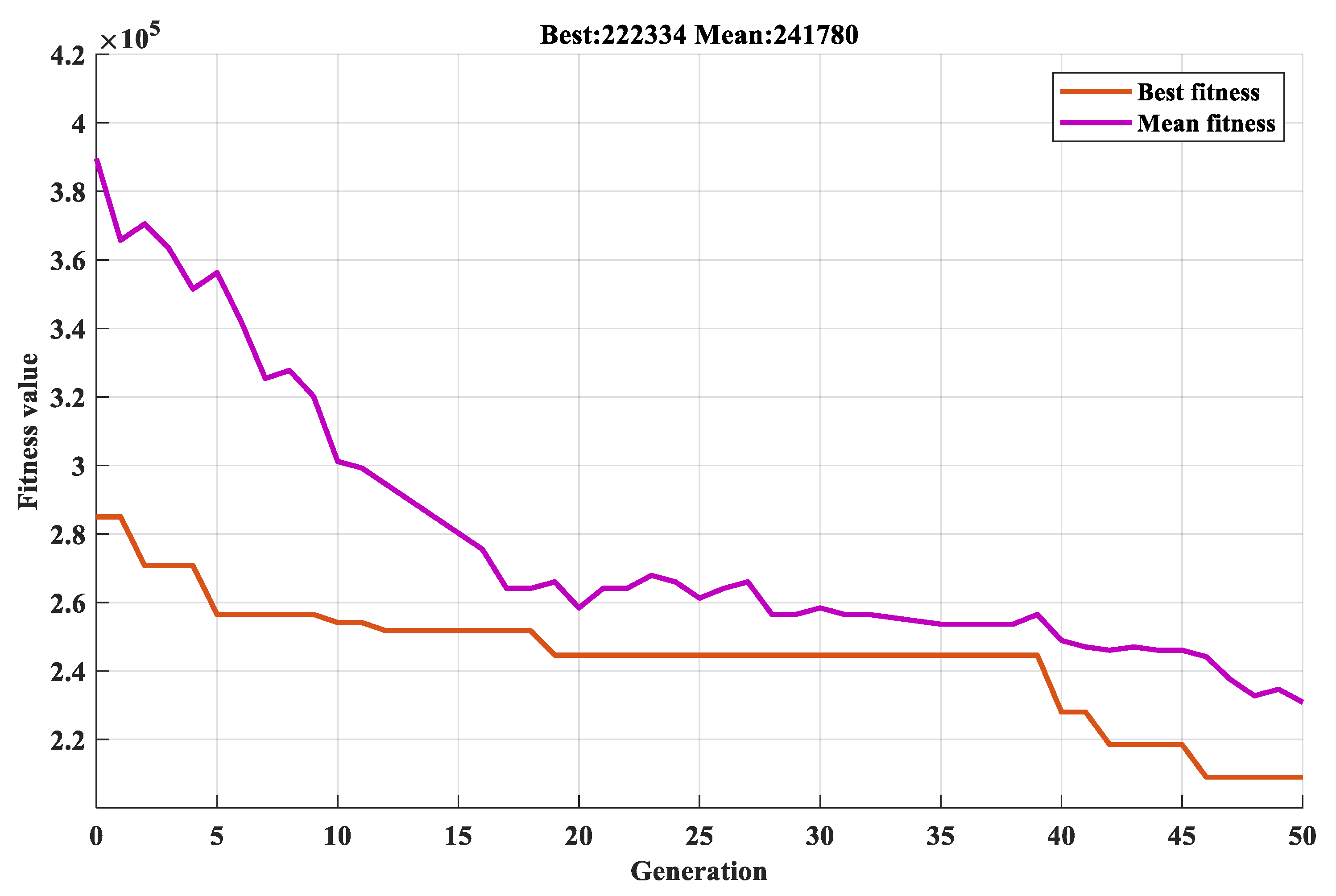
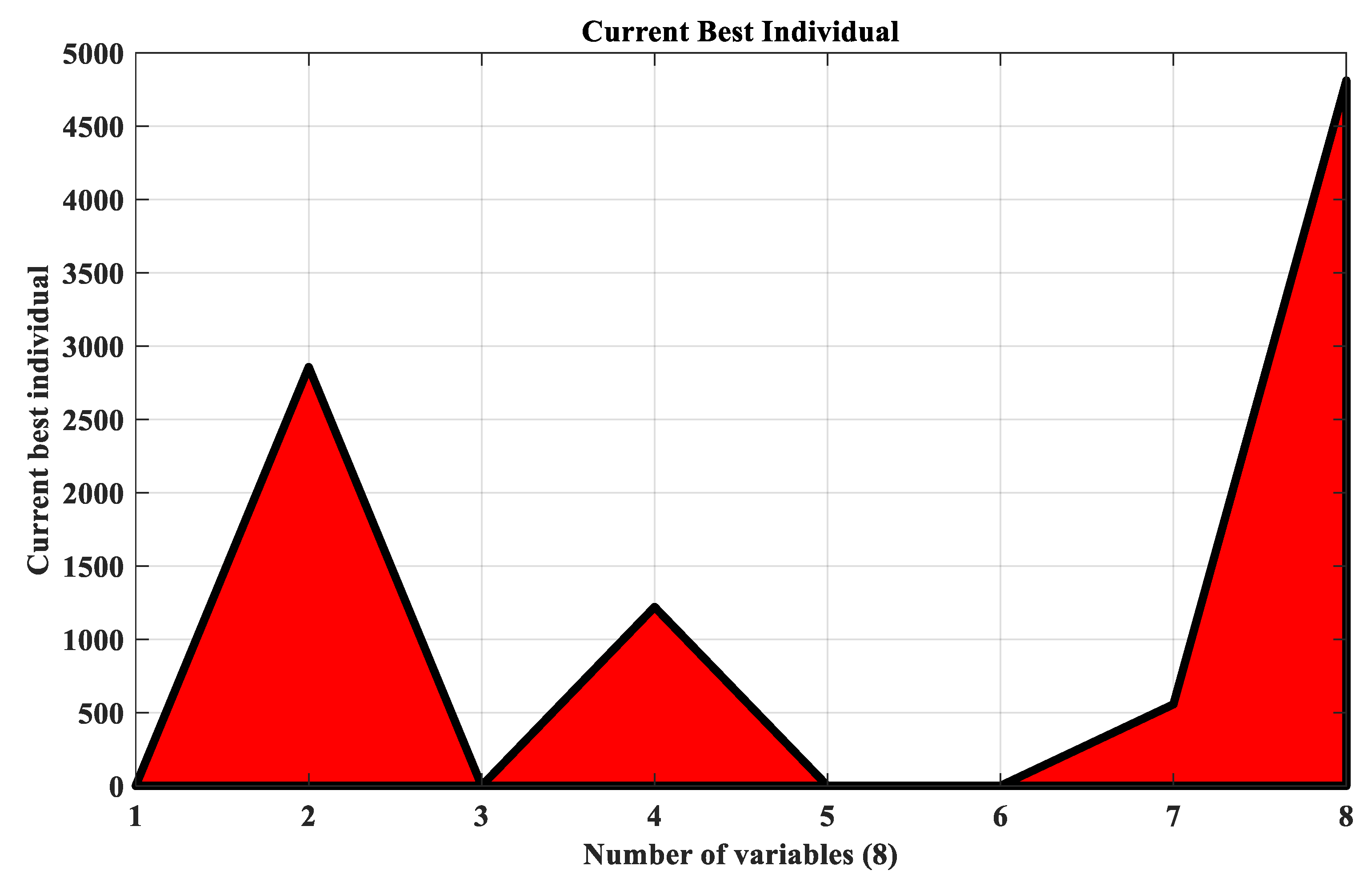
Figure 9 presents the convergence performance of the proposed algorithm while
Figure 10 shows the results for best individual results per each of the eight variables in our study.
The searching criteria stop if any of the following conditions have been reached; (i) The hybrid algorithm reached the maximum allowed number of iterations, (ii) Same solutions have been obtained for a predetermined number of iterations, or (iii) Same set of solutions (by means of particles) are found in the same solution space.
4. Experimental Results
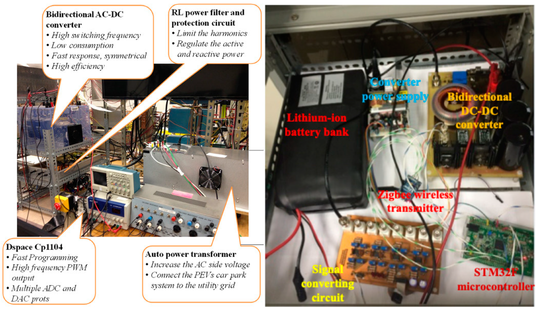
To verify our proposed methodology, we demonstrate its concept via hardware-in-the-loop testbed at the Florida International University. A MATLAB/Simulink model is built and is shown in
Figure 11. Specifically, it resembles the hybrid microgrid that consists of a synchronous generator and programmable AC loads connected at the AC side, with a PV emulator and a lithium–ion battery to resemble EVs activities at the DC side along with programmable DC loads. An interlinking bidirectional converter is utilized to connect the AC/DC sides of the microgrid.
Figure 12 shows the hardware components at our testbed lab to perform this study. We set the simulation time to be 4 seconds and applied the vector-decoupled with the optimization parameters obtained via the hybrid algorithm, as illustrated in this work.
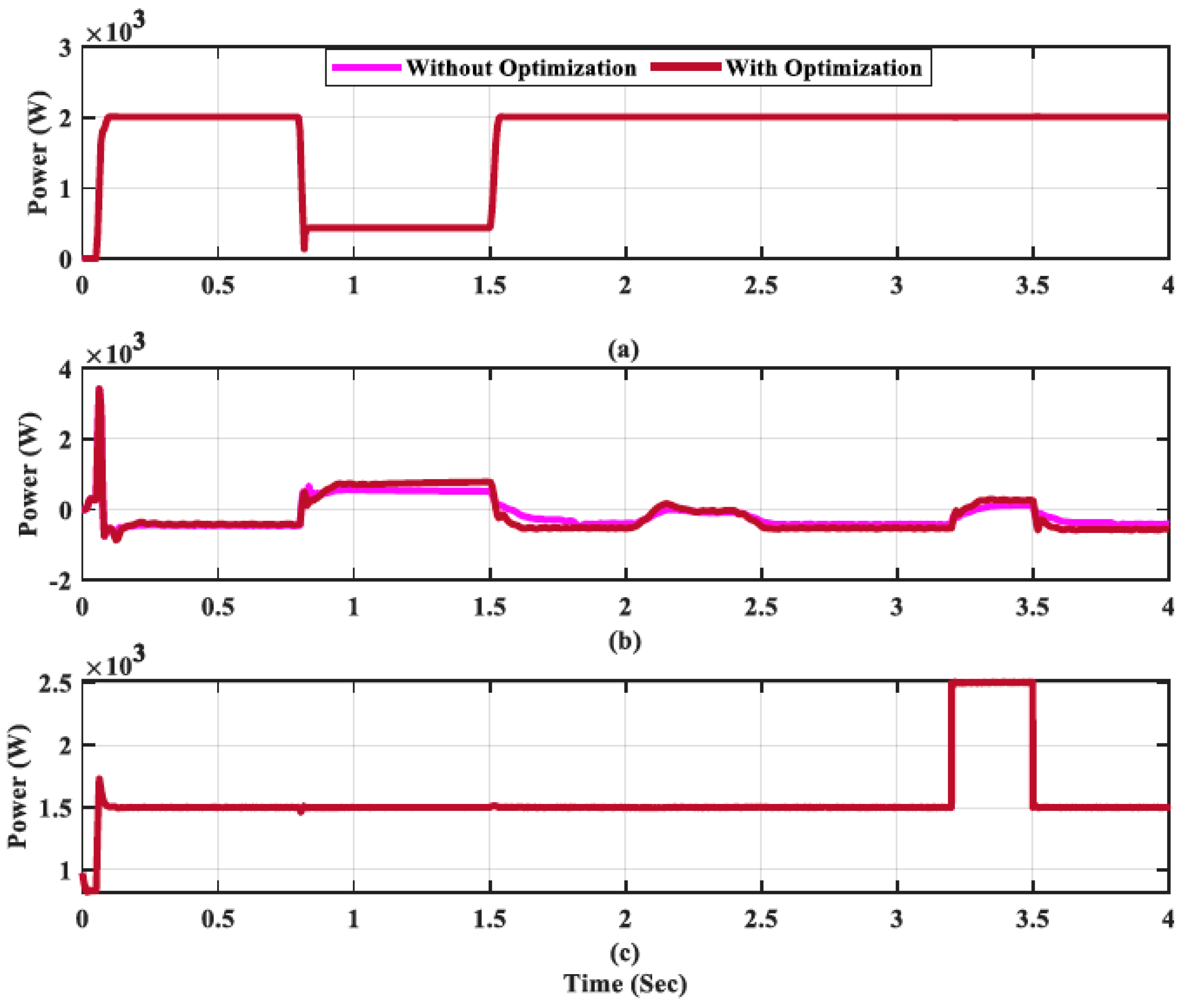
Figure 13,
Figure 14 and
Figure 15 show the results, with the output of the PV system dropping from 0.8 to 1.5 s as a result of a hypothetical cloud-dense during a specific time of the day, as shown in
Figure 13a.
To be able to manage such deficiencies in PV generation, the microgrid operator allows more EVs discharging events via reduced monetary incentives to encourage the consumers to discharge during once such situation incur at any potential time of the day, as shown in
Figure 13b. In order to compensate for any potential lack of discharging due to the randomness of consumer participation, the AC generator increases its output to meet the remaining loads to keep the microgrid’s operation in balance. This is demonstrated in
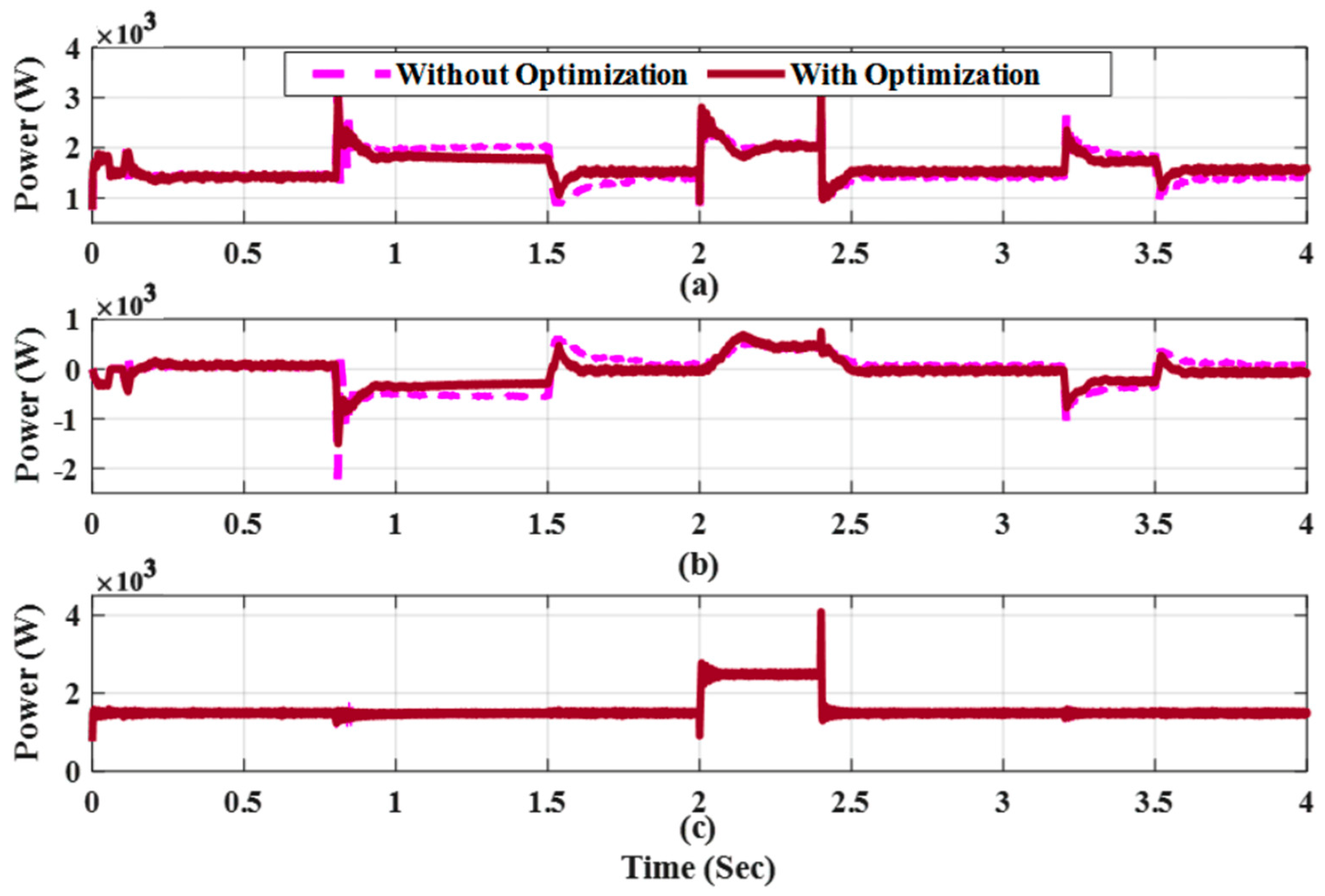
Figure 15a and is achieved in a rapid manner to keep the system’s voltage and frequency levels unaffected.
Figure 13c and
Figure 15c present the load profiles, where considering the optimization of the vector-decoupled parameters, based on our hybrid algorithm, lead to more contribution from the AC generator side. It noted that assuming coordinated large-scale participation of EVs discharging, the stress on the synchronous generator could be furtherly alleviated. Such incorporation of EVs in the balancing criterion could be then estimated, at the discretion of the microgrid’s tertiary control, which eventually contribute to a smarter charging and discharging scheduling.
As noted from
Figure 14a–c, the pulsed load of the DC side is energized for a total duration of 0.4 seconds between the timeslots 2 to 2.4 s, with another energized pulsed load between the timeslot 3.2 to 3.5 s. Following our proposed mechanism, the controller performs the controlling procedure accordingly and mitigates the pulsed loads by balancing the power-sharing to a proper ratio to prevent any potential disturbances on the microgrid operation. Specifically, the controller force reversed power flow to the DC part of the hybrid microgrid if the DC loads are energized. Such a process is shown in
Figure 15b in the case of negative power, which is an indication of power flow from the AC part of the grid to its DC side to compensate for the deficiency at the DC voltage level. As shown in
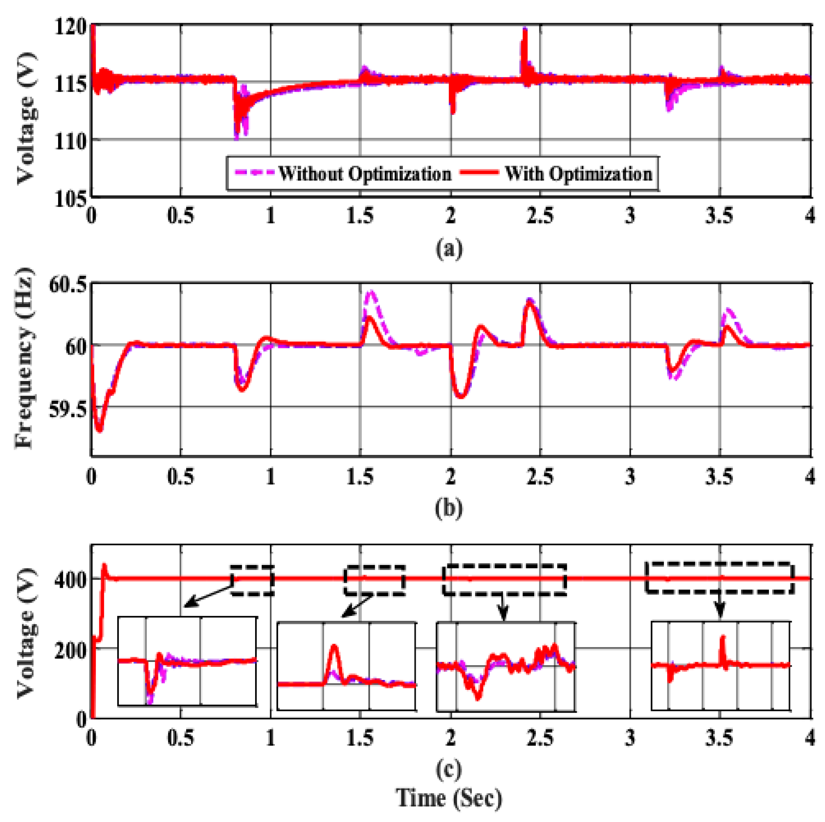
Figure 14, our controlling mechanism achieves stable and secure microgrid operation by acceptable variations of the frequency and voltage levels. Although voltage variations are a bit high, we emphasize that they remain within a safe and acceptable level of operation.
Figure 15c shows the DC side voltage level and is stable around the reference value of 400 V. As expected, variations of the generator output lead to fluctuations of frequency levels that exceed allowable and safe limits, which could trigger the operation of under- or over-frequency protection relays. However, these fluctuations are significantly reduced and managed following our proposed control mechanism based on optimized parameters using APOPSO. This shows the robustness and effectiveness of our proposed technique.
5. Conclusions
In this work, a metaheuristic-based vector-decoupled algorithm for hybrid microgrid energy control and management is proposed. The algorithm aims to ensure safe and stable power-sharing between the DC and AC parts of the microgrid considering variable renewable energy sources, EV charging structure, as well as severe operational condition such as in the case of forced islanding operation. The metaheuristic algorithm provides the interlinking converter with optimized parameters to manage the microgrid’s operation under various load and resources conditions. mechanism enables a smart and rapid. A hardware-in-the-loop implementation verifies and validates the proposed technique and offer stable and robust operation even during islanding situation. Furthermore, stable voltage and frequency levels are achieved and the power sharing between the two parts of the microgrid is accomplished. Specifically, we assumed a reduction at the power level of the DC side due to dense cloud in the time between 0.8s to 1.5s, as shown in
Figure 13a. Accordingly, the controller requests more energy discharge from the EVs during this period to compensate for this deficiency, as illustrated in
Figure 13b, while it allows for power sharing from the synchronous generator located at the AC side as shown in
Figure 15a to assist the deficiency in the DC side. This is pivotal in the balancing of the operation especially in the case of insufficient participation of the EVs to discharge their energy during the scenario of reduced PV output. It is noted from the results that this has been achieved in rapid and robust manner without impacting the load levels. It should be noted that the parameter optimization of the proposed hybrid algorithm allows more participation from the AC side. Since large variations in the generator output may lead to frequency fluctuations, optimization of the parameters is required in this work. This is achieved by optimizing those parameters using the proposed APOPSO algorithm. As can be shown in
Figure 14c, the optimized parameters reduced the fluctuations significantly in comparison with case of non-optimized parameters. Fluctuations in the non-optimization scenario may harm the operation of the hybrid microgrids and could trigger false operation of the over/under frequency protection relays. The success of the hybrid algorithm in reducing the fluctuations indicate its robustness and effectiveness in the hybrid microgrid energy management and control.
Future work is expected to incorporate algorithms that propose dynamic pricing structure to accurately reflect the real-time energy prices as result of control activities in hybrid microgrids. Soon, huge participation of EVs as well as privately owned small-scale PV systems is expected, and a fair pricing structure will be required to encourage more participation from consumers sides. The authors of this work propose a new pricing scheme that allocates special pricing tariff on electric vehicles that charge considering stochastic microgrids operation and energy management [
33]. Furthermore, the authors suggest that this area of research needs further investigation. Additionally, future work is also anticipated in regard with machine learning applications in smart control of power quality problems as a result of large adoption of EVs in hybrid microgrids. In such studies, smart control is integrated to enhance the voltage fluctuations and harmonics as result of stochastic large-scale integration of EVs activities on microgrids.


