Article

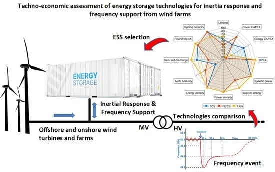
Techno-Economic Assessment of Energy Storage Technologies for Inertia Response and Frequency Support from Wind Farms

1
Department Industrial Systems Engineering and Design, Universitat Jaume I, Av. Sos Baynat s/n, E-12071 Castelló de la Plana, Spain
2
Department of Electronic and Electrical Engineering, University of Strathclyde, Glasgow G1 1XQ, UK
*
Author to whom correspondence should be addressed.
Energies 2020, 13(13), 3421; https://doi.org/10.3390/en13133421
Submission received: 17 May 2020 / Revised: 17 June 2020 / Accepted: 29 June 2020 / Published: 2 July 2020

Abstract

:
This paper provides the result of a techno-economic study of potential energy storage technologies deployable at wind farms to provide short-term ancillary services such as inertia response and frequency support. Two different scenarios are considered including a single energy storage system for the whole wind farm and individual energy storage for each wind turbine (located at either the dc or the ac side of its grid-side converter). Simulations are introduced to check the technical viability of the proposal with different control strategies. Power and energy capability requirements demanded by both specific services are defined for each studied case based on present and future grid code needs. Based on these requirements, the study compares a wide range of energy storage technologies in terms of present-day technical readiness and properties and identifies potential candidate solutions. These are flywheels, supercapacitors, and three chemistries out of the Li-ion battery family. Finally, the results of a techno-economic assessment (mainly based on weight, volume, lifetime, and industry-confirmed costings) detail the advantages and disadvantages of the proposed solutions for the different scenarios under consideration. The main conclusion is that none of the candidates are found to be clearly superior to the others over the whole range of scenarios. Commercially available solutions have to be tailored to the different requirements depending on the amount of inertia, maximum Rate of Change of Frequency and maximum frequency deviation to be allowed.

Graphical Abstract

1. Introduction

In recent years, the amount of converter-based power generation has increased steadily [1], while at the same time conventional synchronous-based power stations are being decommissioned [2]. In this context, wind power is one of the most successful generation technologies in the coming low-carbon power generation mix. In Europe, the total amount of installed wind capacity grew from 65 GW in 2008 to 205 GW in 2019, yielding 417 TWh of production that year, and supporting 15% of the EU’s electricity demand [1].
A high degree of penetration of converter-based power generation changes the standard power system operation, control, and protection [2,3]. One of the main consequences of this new scenario is the reduction of the total system inertia [4]. Clear examples of this tendency are small electrical systems like Ireland [5] or Great Britain [3] that have experienced a steady reduction of their systems’ inertia, a trend expected to continue during the following years. It is important to recall that inertia in power systems comes from the rotating mass of its synchronous machines, turbines, and generators. This rotating mass releases or absorbs energy in the case of a power imbalance event and slows the frequency change [6]. Some system operators believe that this reduction in system inertia will endanger their grid operation capability and, therefore, future converter-based systems are likely to be required to provide inertia response (IR) [7]. Some calculations have already been published on the minimum inertia requirements to cope with the union for the co-ordination of transmission of electricity (UCTE) limits and also the minimum synchronous generation to keep connected and assure the response [8]. Alternatives such as active dispatch [3] or synchronous condensers [9] have also been considered and in some cases combined. Ref. [10] introduces a Gaussian particle swarm optimization algorithm to simultaneously co-optimize the dispatch of synchronous generators and their frequency services, wind reserve, and synchronous condensers.
Another service that might need to be reshaped in a grid with high penetration of converter-based generators is the frequency support (FS) or primary frequency control [11]. Currently, synchronous-based power stations with a fast governor action, e.g., combined-cycle power stations, keep the power system balance by increasing or reducing the amount of power injected by the gas or steam turbine engine in the few seconds after a transient frequency event. As the relative capacity of synchronous machines decreases, in the system converter-based generation is also being studied for the potential to deliver FS [12]. Renewable energy sources and energy storage systems (ESS) have been recognized for the potential to provide a mixture of inertial and frequency support services. Ref. [13] identifies both as devices that the Australian Electricity Market Operator should pursue to deliver fast frequency response in a study that considered the benefits and requirements of inertial based frequency support.
The provision of IR and FS implies the converter must have access to a sufficient source of instantaneous energy. Many control strategies assume an infinite source at the DC link, often representing either a WT or a WT plus ESS [14,15,16]. This assumption is not appropriate as (1) using WT kinetic energy has been shown to increase vibrations at structural frequencies [17], (2) an existing converter designed for a WT could not accommodate its nominal power output plus the power required for inertial provision from an ESS [18], and (3) the control parameters can be affected if the DC link voltage stability is not granted [19]. It seems clear then that such a service will require the introduction of a well-defined ESS and, potentially, increasing the size of the wind turbine’s power converters [20]. In some cases, the installation of a new power converter might be even necessary [21]. ESS are becoming a solution for multiple grid (front-of-the-meter) and behind-the-meter applications around the world due to technological price reduction [22]. ESS are also supporting renewable integration by reducing the inherent production variability of technologies such as wind and solar. However, the selection of a specific ESS for IR and grid FS in wind farms is quite a specific topic that has not been explicitly answered in the open literature to date. This work intends to cover this gap by introducing a techno-economic discussion of the potential ESS technologies to be deployed at wind turbine or wind farm level to provide IR and FS. In this sense, the initial analysis on the power and energy capacity requirements to offer these services paves the way to the ESS selection and subsequent discussion.
The paper starts with a review of the current state of renewable energy sources interfaced with ESS and their provision of virtual inertia in Section 2 before describing the inertia response and frequency support services in Section 3. Section 4 presents the power and energy capacity requirements to provide these services, introduces some simulations on inertial responses provided by a WT integrating an ESS and, then, various candidate ESS technologies are identified according to the requirements and specifications. Section 5 focusses on the technical description of these candidates whereas in Section 6 a technical (weight, volume, and lifetime) and cost discussion and comparison among the solutions is provided. Finally, some concluding remarks are presented in Section 7.

2. Review of the Current State of Literature Regarding Renewable Energy Sources Interfaced with Energy Storage and Their Provision of Virtual Inertia

Different power converter control strategies are proposed in the literature to provide IR and FS. First approaches were suggested in [14,15]. Authors proposed the addition of two control loops to the standard vector control of the converter, one for the IR and another for the FS. They termed this strategy power voltage current control for inertia emulation (PVCCI) and it proved its potential to replace the inertia previously provided by synchronous machines during frequency events. PVCCI is a grid following approach that, despite being capable of emulating inertia, must synchronize with the grid frequency and appears as a current source. A different proposal implements the well-known frequency- and voltage-drooping mechanisms into the so-called virtual synchronous machine (VSM), utilizing low order mechanical and electrical models to represent the dynamic response of a synchronous generator [16]. VSM does not require grid synchronization after initialization and appears as a stiff voltage source so is considered to be grid forming. Ref. [23] proposes the integration of an improved governor in the controls to regulate the active output power of variable speed WTs during transient events; adapting the P-f droop coefficients in real time enables enhanced IR and FS capability. A similar approach is introduced in [24] that shifts the maximum power point tracking curve of the WT according to the grid frequency deviation and the droop control. Ultimately the active power output relies on the available inertial resources. The VSM converter offers an increasingly popular route for IR and FS [25]. VSM can utilize higher order models of the swing equation to mimic synchronous machines and provide IR while it uses a similar control scheme as traditional power converters for FS [26]. An extended VSM control strategy is proposed in [27] that adds a fast frequency response (FFR) droop block to the VSM power control. A VSM control technology based on Hamilton approach is introduced in [19] to support the frequency and enhance the suitability and robustness of the system. Ref. [28] compares grid forming and grid following approaches; the transient responses of a VSM and a PLL-based inertia emulation are analyzed showing the dependence on the synchronizing method. Finally, the authors present a comprehensive review of virtual inertia-based inverters in modern power systems in [29].
Beyond the inertia emulating strategies, the control must consider the specific operation of individual energy storage components and technologies and ensure their potential to respond to transient events. Ref. [30] discussed a comprehensive machine, storage, and grid side converter control configuration that enabled a WT with DC connected energy storage to continue VSM operation throughout levels of storage state-of-charge (SOC) and wind availability. Ref. [31] adopted a fuzzy logic control approach that considered the size of ESSs to enable wind farms to take part in short term FS. Ref. [21] introduced a focused control approach for hybrid ESS that allocated short and long term components of the FS to the ESSs with corresponding response capabilities. Ref. [32] developed a control strategy for batteries providing IR and FS that restricted charging to stable frequency periods to remove the impact of SOC on the frequency signal. An up-to-date review of the control of VSGs and appropriate ESSs is presented in [33], which highlights the need for further work to identify the optimal size and type of ESS for specific applications.
Techno-economic analysis of energy storage has been identified as a key tool to define optimal and grid-ready solutions for issues regarding the rising penetration of renewable energy sources. A hybrid ESS configuration was found to be the lowest cost balancing mechanism for variation of load profiles in otherwise low-flexibility networks in [34,35], analyzing the feasibility of storage options to minimize the effects of wind power variability on the Australian network. Ref. [36] identifies the most cost-effective configuration of photovoltaics and storage to supply an islanded grid. Ref. [37] optimizes the size of ESS configurations to maximize a revenue objective function via frequency services but does not compare an exhaustive list of technologies on the short dynamic scales that are pertinent to virtual inertia. Although studies are being carried out that compare the cost and performance of ESSs the benefit in their use comes when the analysis is focused for an exact application and environment and the list of technologies spans a wide range. Accordingly, to drive useful progression towards the deployment of ESSs with WTs for IR and FS, techno-economic analysis needs to be carried out for that specific application.
The analysis needs to consider a range of mature ESS technologies that are appropriate for IR and FS. Ref. [38] provides a review of ESSs that are applicable to support the intermittent generation of renewable energy sources. Ref. [39] delivers another review of the properties of these storage technologies with a focus on the methods for sizing the devices according to the function specifications. Such a comprehensive approach is necessary to enable the confident development of IR solutions. Ref. [40] carried out a techno-economic study of ESSs to balance power for VSMs in 2009 but the transformation of the storage industry and the virtual inertia field in the last decade demands a more up to date analysis. More recently, Ref. [18] identified the forerunners in storage technologies for inertia provision, while the authors of [41] covered the modelling and control of a frequency supporting energy storage device. Ref. [42] analyzes the control and cost of a BESS used in parallel to wind generation that is actively curtailed for frequency support. None of these studies confirmed the optimal ESS to support the frequency response of WTs.
The remainder of this study is carried out to clearly compare a wide range of ESSs in terms of present-day technical readiness and properties and industry-confirmed costings. The technologies are compared for the specific function of inertial provision and frequency support in conjunction with a wind farm and are considered at three locations relative to the farm that have rarely been considered in the literature.

3. Inertia Response and Frequency Support

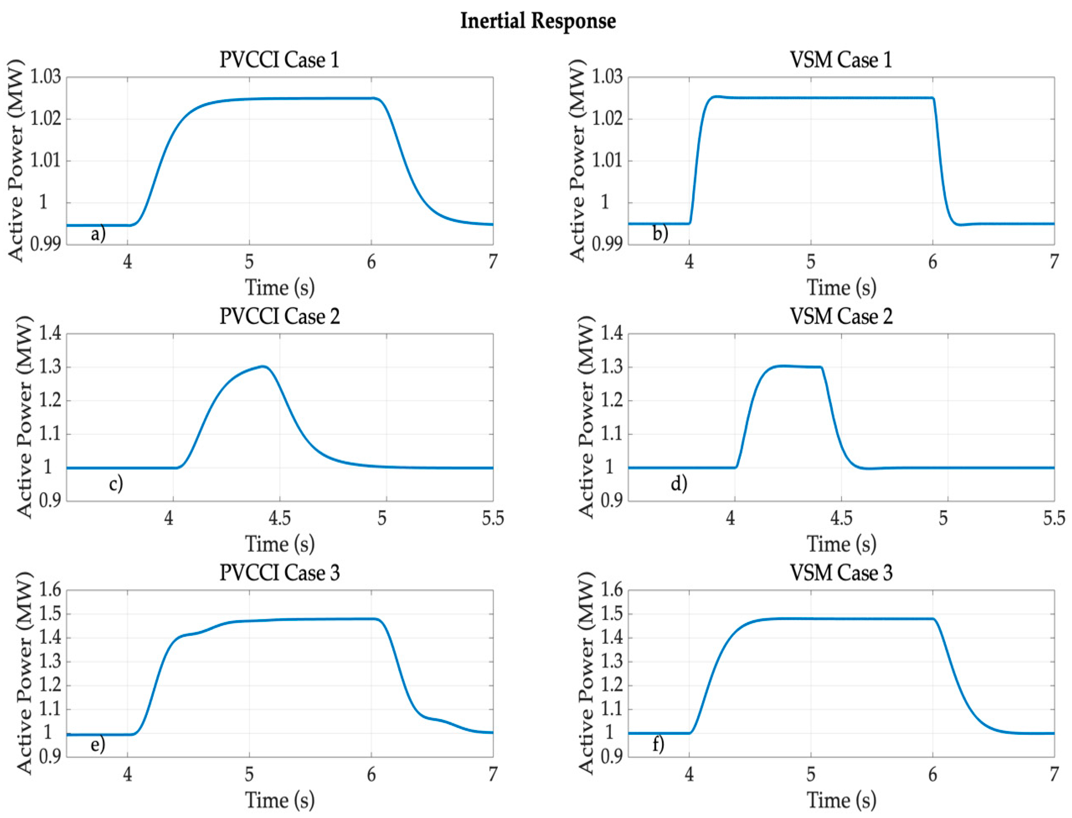
3.1. Inertia Response

Frequency is used as a balancing signal in electrical power networks. When a power deviation occurs in a system dominated by synchronous machines, the balance between generated and consumed power breaks, and the frequency of the system starts to divert from its nominal value. Initially, the huge rotary masses (with high inertia) of the synchronous machines maintain the stability of the system before the electrical governors can react in the following seconds. The rotating inertia slows down the frequency change by delivering or absorbing transient power from the system [6]. The dynamics of a synchronous machine are given by the Swing equation:
J · d 2 δ m d t 2 = P m P e ,
which, according to the definition of J [7], i.e., the rotor moment of inertia:
J = M ω s = 2 · H s · S r a t e d ω s ,
can be written as:
2 · H s · S r a t e d ω s · d 2 δ m d t 2 = P m P e ,
where M is the angular momentum, Hs is the synchronous machine inertia time constant (ratio of kinetic energy to power), measured in seconds, Srated is the synchronous machine rated power, ωs is the synchronous speed, in rad/s, and Pm and Pe are the synchronous machine mechanical and electrical powers, respectively.
Therefore, taking into account the Swing equation, one can understand the IR as the capability of the machine to provide active power and that it is proportional to the second derivative of the angle.

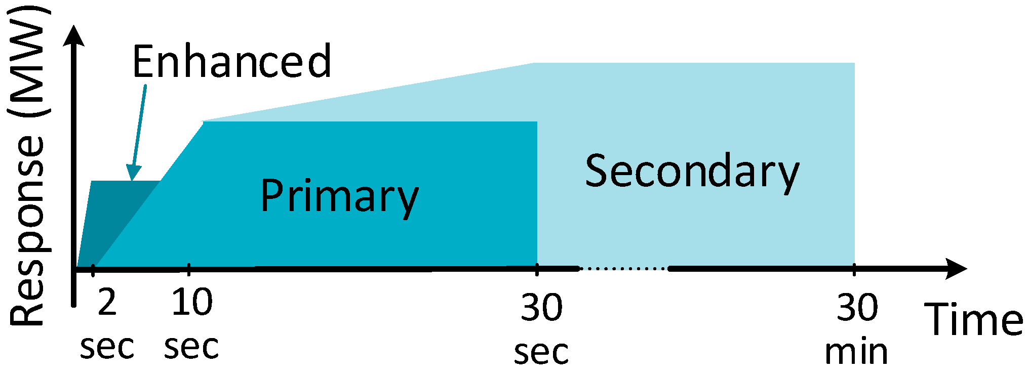
3.2. Frequency Support

When a frequency event occurs, the inertia slows down the Rate of Change of Frequency (RoCoF) and provides some time for the primary frequency control to react. This service has to be delivered by synchronous-based power stations with fast acting governors [6]. The FS is directly proportional to the frequency deviation as:
P F S = K F S · Δ ω ,
where KFS is the frequency controller gain and Δω is the steady state frequency deviation.
In the UK the services available in case of an under-frequency event can be seen in Figure 1 [3]. These are the enhanced frequency, the primary response, and the secondary response. The primary response and secondary response are classic services provided by synchronous-based power stations that respond to frequency deviations at different response and operation time horizons, starting at 2 and 10 s, respectively. On the contrary, the recently introduced enhanced frequency response provides, and requires, a faster response and targets mainly converter-based generation.

4. Energy Storage Requirements, Potential Placement, and Candidate Technologies

As discussed in the introduction, the presence of ESSs for different front-of-the-meter and behind-the-meter applications is increasing as prices for the different technological solutions decrease. However, the introduction and selection of specific ESSs for IR and FS in wind farms has not been analyzed in depth mainly because of insufficient grid code requirements [43]. Nonetheless, this is an increasingly important topic for an enhanced integration of wind farms and will certainly be a grid connection requirement in the future for systems with high wind penetration.

4.1. Energy Storage System Requirements

The first step to analyze the technical and economic viability of introducing an ESS to provide the IR and FS services at a given WT or wind farm is to determine the energy and power ratings these require. In this sense, the present work focuses on solutions for inertia and frequency support at a 501 MW onshore wind farm with 167 wind turbines with a rated power of 3 MW. Alternatives at both WT and farm level are analyzed. Then, the amount of power and energy required to provide an IR during a frequency event can be obtained by manipulating the Swing equation as:
P s t o r a g e = 2 · H · S n ω s · ω ˙ m a x ,
E s t o r a g e = 2 · H · S n ω s · Δ ω m a x .
In this sense, both magnitudes will mainly depend on four different factors:
  • Sn—rated power of the wind turbine or wind farm where IR is to be implemented (in MW).
  • H—equivalent inertia constant to be emulated (in seconds).
  • ω ˙ m a x —maximum RoCoF defined by the grid codes (in Hz/s).
  • Δ ω m a x —maximum frequency deviation accepted by the grid operation code (in Hz).
This work considers various combinations of these four factors. Table 1 and Table 2 introduce the resulting capacity requirements of the ESS to be installed at 16 different study cases at both a single 3-MW rated-power WT level or at a 501-MW rated-power wind farm level to provide both IR and FS. Note how the power and energy capacities required for providing FS are based on the rated power derived for the IR service, using the Swing equation, and on the amount of time that the generator would be supposed to offer FS service. In this sense, this work considers 10 s as the duration for FS in line with the enhanced frequency response requirements [44] (Figure 1). For each of the factors above (inertia, maximum frequency deviation, and RoCoF), two extreme values are taken into consideration. The minimum value of RoCoF and Δωmax are defined in accordance to the European grid codes [44] while the maximum values are inspired by an ENTSO-E document describing future grid needs [45]. The minimum and maximum inertia values are taken from traditional synchronous machine values [6].
The resulting required capacities range from 60 to 2400 kW in power, and between 0.03 and 6.67 kWh in energy at the WT level. At the wind farm level, the capacity ratings are between 10 and 400 MW in power and from 5.55 to 1111 kWh in energy. Therefore, results in Table 1 and Table 2 show that both services represent high-power and low-energy demanding applications.

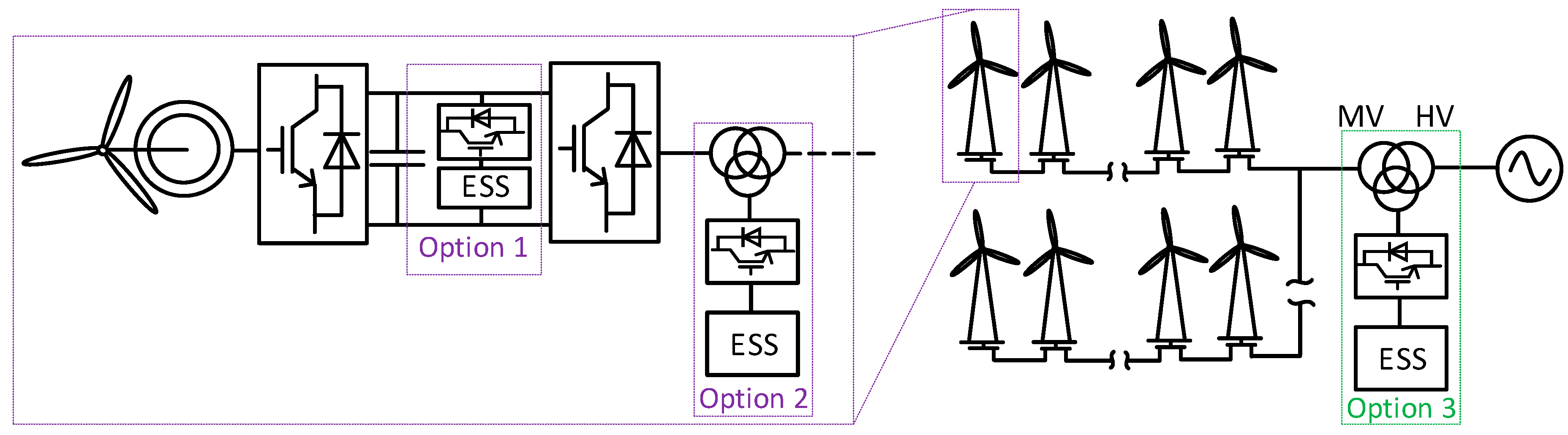
4.2. Potential ESS Placement

Apart from considering a generic introduction of ESS at wind farm or WT level, three potential placements are analyzed in this work and are shown in Figure 2. Two are considered at the WT level, i.e., at the DC link (Option 1) or at the AC side of the turbine grid converter (Option 2). From an energy perspective, there is no difference between Option 1 and Option 2. Conversely, one location is considered at wind farm level and refers to its point of common coupling with the grid (Option 3). Each of these options have already been suggested in the literature for different applications. Ref. [20] proposed a strategy to operate a DFIG for virtual inertia using a capacitor connected in the DC link of the partially rated converter. The author notes that placement here would require the rerating of the grid side converter. Ultimately, the grid side converter capacity is expected to constrain the operation of DC connected ESS as a WT approaches rated output. Alternatively, the connection of a battery energy storage system (BESS) on the AC side of the grid side converter was proposed by [19] for operation as a virtual synchronous generator. ESSs have also been suggested on the AC side on a larger scale, serving entire networks, to increase wind utilization where there is high penetration of renewable energy sources [46]. Beyond the control and inverter characteristic implications, further discussion on the pros/cons of the different placement options to shelter the different ESS under analysis are introduced in the coming sections.

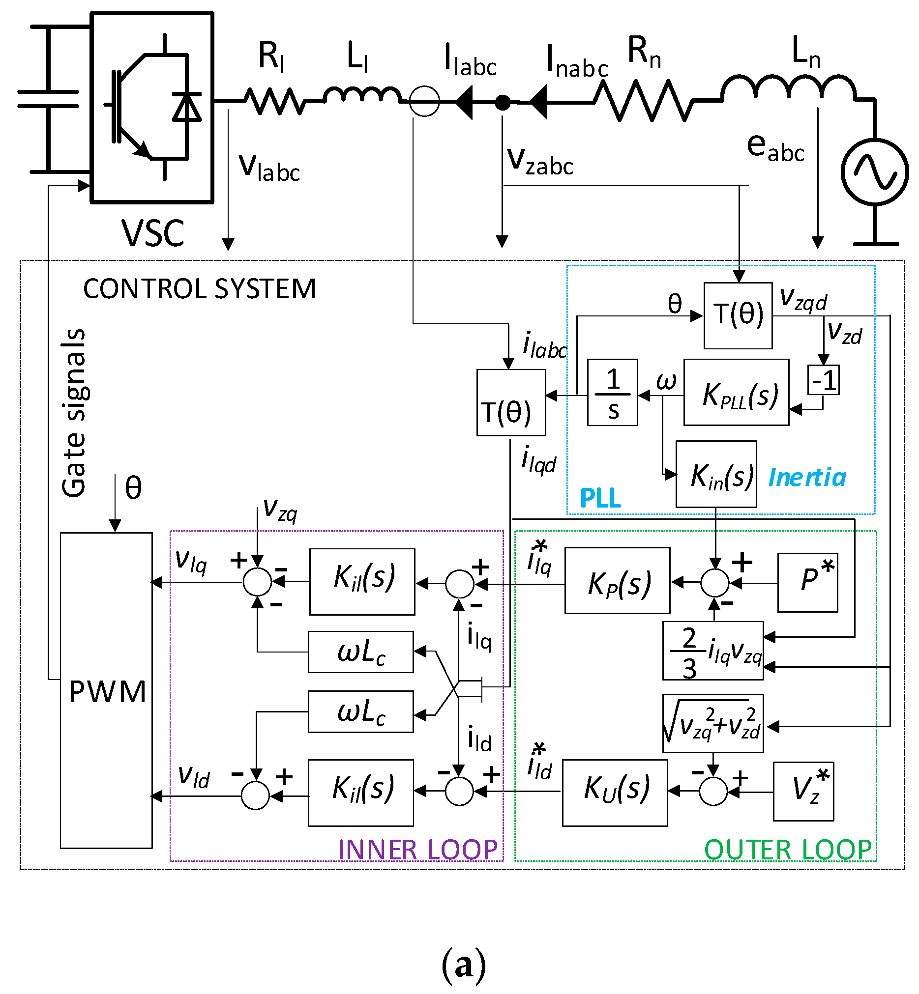
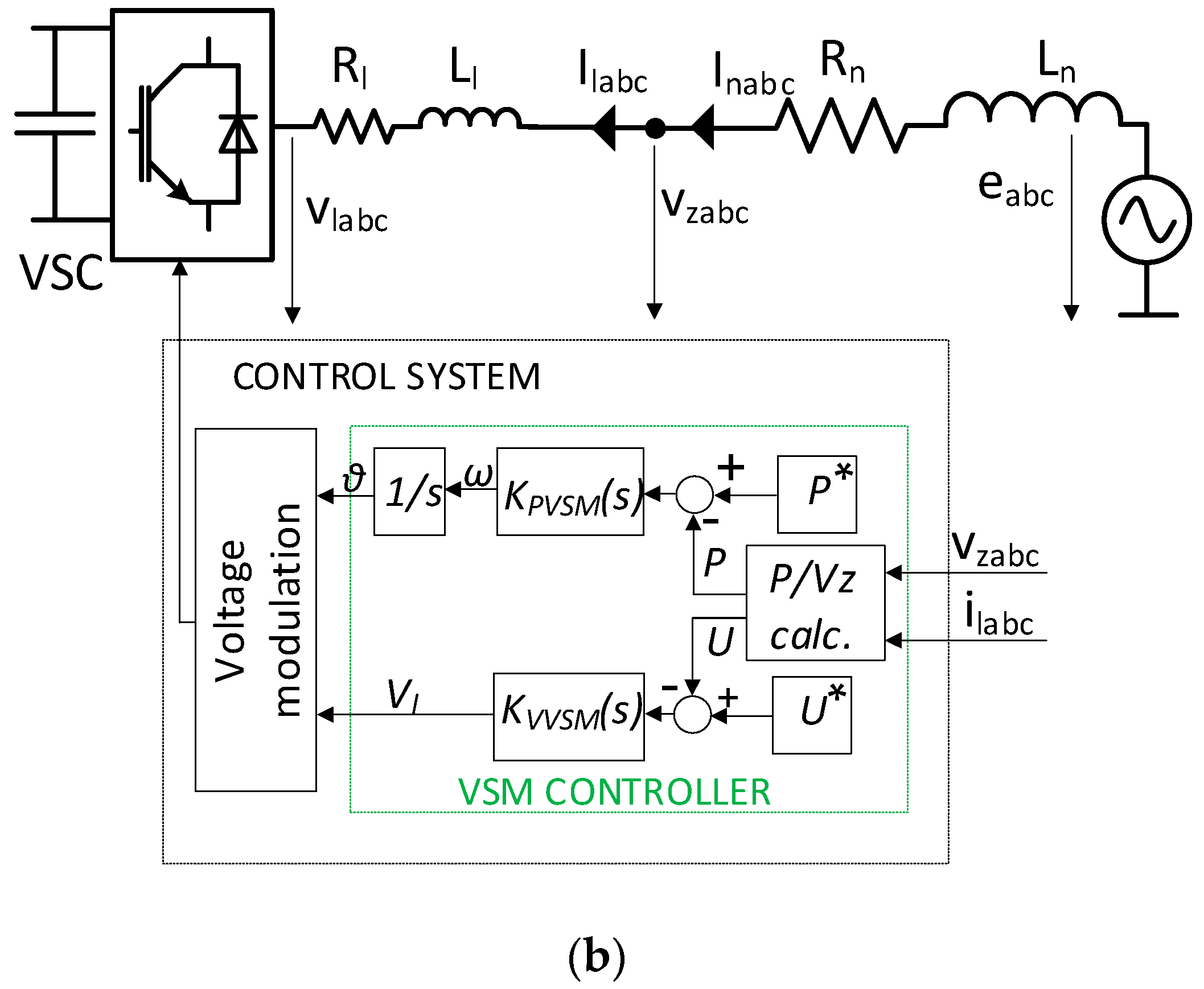
4.3. Potential Control Strategies

In order to analyze the energy response of a hybrid wind and energy storage system and confirm the values derived from the swing equation in Section 3.1, simulations were performed using Matlab®. These reproduce the response of the ESS converter when implemented in parallel to a grid connected wind power system and subject to two different control methodologies, one for a grid-following and another for a grid-forming converter configuration. These methodologies cover the two main trends defined trough the literature.
First, the PVCCI strategy from [14] is used for the grid-following case. In this solution, the conventional current control inner loop is unchanged, but a derivative term is added to the power channel in the outer loop. The derivative acts on the grid frequency, measured by the PLL, altering the power set point to include the inertial response. Since this study aims to compare the inertial response of a WT with storage system under different control strategies, the proportional branch proposed in [14] for subsequent frequency support is neglected. The resulting control strategy is pictured in Figure 3a.
Second, a VSM controller [16] is used for the grid forming case. This implements the swing equation within the power control channel, which sets the voltage angle according to variations in active power. A second channel sets the voltage magnitude according to changes in the grid voltage. This strategy is pictured in Figure 3b and exhibits a different approach to control a grid converter for inertia emulation.
Both the PVCCI and VSM strategies were tuned to provide the IR for Cases 1–3 in Table 1, which represent a grid with low or high inertia and varying RoCoF requirements. The maximum frequency deviation was kept at 1 Hz for this analysis. The grid was emulated by its Thevenin equivalent with the following parameter values:
R T H = 0.0012   Ω , X T H = 0.012   Ω , and V T H = 565   V
The PVCCI inertial controller equation is K i n = k i n k d N s s + N where k i n is the proportional inertial gain, k d is the derivative gain, and N is the filter coefficient. The VSM power controller equation is K P V S M = k p V S M s + k i V S M s where k p V S M is the proportional VSM gain and k i V S M is the integral gain. The parameters for each controller in each case are shown in Table 3.
Then, the grid frequency is set to change in the system from 50 Hz at t = 4 s to 49 Hz at either t = 4.4 s or t = 6 s, depending on the RoCoF to be emulated (2.5 or 0.5 Hz/s, respectively).
The inertial responses provided by the two controllers are compared in Figure 4. The ESS instantaneous power responses effectively evolve towards the power values defined in Table 1. The overall energy delivered during the frequency events is defined in Table 4. The energy values are in agreement with the requirements in Table 1. Finally, note that for each of the three cases simulated and represented in Figure 4 the VSM controller can be tuned to be less damped (to stabilize faster) whereas the PVCCI strategy is unstable for low damping so exhibits a slower response. However, both present very similar responses in terms of power and energy and agree with the expected values.

4.4. Selection of Candidate ESS Technologies

Several ESS technologies have been classified and analyzed by different authors for grid applications [47,48,49,50]. Figure 5 overlays the previously calculated and simulated ESS power and energy capacity requirements for IR and FS on a standard ESS “rated power vs. energy capacity” chart [51]. From this figure note the suitability of the technologies on the left hand side of the chart (low energy ESS), including supercapacitors (SCs), flywheels (FESS), and lithium-ion batteries (LiBs).
Other technologies could also be considered as candidates. These include the superconducting magnetic energy storage (SMES) and the small compressed-air energy storage (CAES) technologies. Additionally, the increasingly interesting hybrid ion capacitors (HIC), or even some very well-known and extensively commercialized types of batteries, such as lead-acid (LA) or Sodium-Sulphur (NaS) technologies, could be an option. Nonetheless, all of them are disregarded as candidate solutions for IR and FS for the following reasons. For instance, both SMES and small CAES are non-mature solutions still being tested at laboratory level [52,53,54,55,56]. HIC (both Li- and Na-based) face a similar issue [57] as CAES, and their electrical characteristics, in terms of energy density, are halfway between LiBs and SCs. Although some models have been commercialized (by companies such as LICAP, JM Energy, or Taiyo Yuden), their technological hybridization still requires further investigation to completely characterize them and make them competitive in terms of cost and reliability for high power applications. On the other hand, cheap LA battery technology has been long and widely used for over 200 years but presents important limitations with regard to specific power, specific energy, and cycling capability [58,59] when compared with the identified candidate technologies. Finally, although the NaS batteries developed and commercialized by NGK Insulators together with Tokyo Electric Power in 1987 could be considered, they require high internal temperatures to keep electrolytes in a molten state. Thus, they are not well suited for power applications despite their high energy density and efficiency, excellent cycle life, and low self-discharge.

5. Technical Discussion on ESS Candidates

According to the sizing specifications, the following discussions focus on the three highlighted technologies: SCs, FESSs, and LiBs.

5.1. Supercapacitors

This technology, also known as ultracapacitors (UC), is classified within the group of electromagnetic energy storage systems, since it stores energy in the form of an electric field within a power capacitor. The amount of energy stored by each SC depends on both its capacitance value (C, in Farads) and the voltage (V, in Volts), as expressed by:
E s t o r e d = 1 2 · C · V 2
When a SC exchanges energy with the network, its voltage varies and the amount of energy released/absorbed is determined by the value of C and the voltage change. Considering the operation requirement of the converters connected to the SC, the usual voltage operation range varies from 50% to nominal voltage, and thus, the amount of energy that a SC can exchange accounts for 75% of the total energy capacity.
Three main industrial contenders can be identified worldwide (Maxwell Technologies, Skeleton Technologies, and LS Mtron Ltd.) presenting similar SC solutions in their catalogues. In general, SCs are well adapted to applications that require very fast high-power responses (with C-rates beyond 100 C) but with low energy capacity requirements. They are also tolerant to frequent and rapid discharges and have easily trackable state of charge (SOC) and state of health (SOH). Finally, they present high round-trip efficiencies (ranging from 92% to 98%) although they register significant self-discharge ratios (around 15% per day). Based on these characteristics they are usually implemented in applications such as pitch control systems in wind turbines; UPS solutions; voltage restorer systems (VRS); break recovery systems in buses, trains, subways, lifts; bridge power for telecommunications, etc. Although SCs can be a solution for short-term quick response applications they present two main restrictions. Firstly, they are described as lasting for more than 500 k full cycles with a temperature operating range of −40 °C to 65 °C but they can suffer from accelerated calendar ageing at temperatures above 40 °C. Secondly, C values have been increasing in recent years but the voltage at the cell level is still very low (around 3 V per unit). This implies the need to series-connect a large number of SCs in order to achieve sufficient voltage to use in grid connected or high power applications. This decreases the operation security as a single SC failure can risk the whole string. Modularized structures reduce the severity of such a failure event.

5.2. Flywheels

Flywheel technology is based on transforming the electric power into kinetic energy, and vice versa, by accelerating and decelerating a revolving cylindrical mass [60]. The relation between the rotational energy stored, the angular mass of the flywheel (I) and its spinning speed (□) is given by:
E r o t a t i o n a l = 1 2 · I · ω 2
Therefore, apart from the electronics and the reversible electric power motor-generator used to interact with the grid, the core of the technology is the design of the flywheel rotor shape (providing moment of inertia around the axis of rotation) and material (providing mass). There are three different design concepts clearly identified within the flywheel industry [61]. These are the carbon fiber composite rotors by Beacon Power, Stornetic, and Powerthru, solid monolithic one-piece rotors made of steel by Canadian Temporal Power, German Piller, and Californians Amber Kinetics and Vycon Energy, and laminated-steel rotors by Gyrotricity from London. Note the importance of the rotor material and its associated weight since a heavier rotor implies lower rotational speed (ranging from a few thousand RPM for monolithic steel models up to 60,000 RPM for some carbon fiber lab designs), higher capacity bearings (taking into account that bearings are usually the life-limiting element of the system), and a heavier housing. Hence, weight is one of the main limitations of this technology for certain applications, i.e., a 100 kW/5 kW·h steel flywheel system measuring 1 m high and 0.5 m in diameter can weigh around 1 tonne.
The different types of flywheels are mainly proposed for applications that require a high number of daily cycles (e.g., over five per day), high power to energy ratios (5–200 C), high cycle and calendar lifetimes (over 20 years or even millions of cycles), high certainty in the SOH of the system, low maintenance and fast response. Services such as grid frequency regulation and uninterruptible power supply are a clear market niche for them. Flywheels are also proposed for thermally challenging applications. However, high temperatures present the need to cool the generator, usually by means of a simple water cooling system rejecting heat to ambient air. In fact, thermal management is a key factor in flywheel operation and, depending on the type of rotor implemented, different motor-generators are introduced (synchronous reluctance or permanent magnet machines are the preferred options) with varying cooling requirements. Finally, it is important to highlight that some kind of active magnetic bearings are used in most of the high-efficiency models currently available in the market. In this sense, round-trip efficiencies of 85–90% are typically achievable with well-designed motor-generators and power electronics [60].

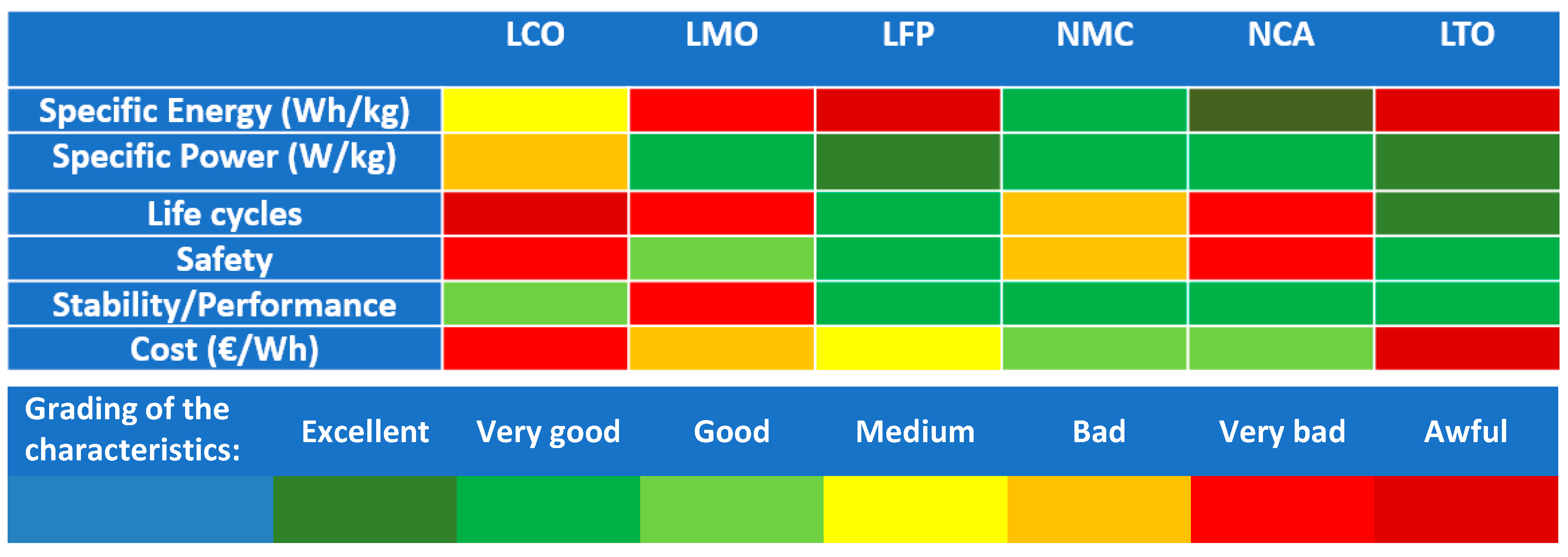
5.3. Lithium Ion Batteries

The label “Li-ion batteries” embraces a great set of different technologies, all including lithium in the form of ionic salt (Li+ rich) as conductive electrolyte, but with different combinations of electrode materials. Currently, up to six different Li-ion chemistries have been commercialized for various applications, as compared in Figure 6. These families, from oldest to newest, include:
  • Lithium Cobalt Oxide (LCO or LiCoO2) released in 1991 and commercialized since 1994 by companies such as Sony and Samsung;
  • Lithium Iron Phosphate (LFP or LiFePO4) commercialized since 1996 by companies such as SAFT and BYD;
  • Lithium Nickel Cobalt Aluminum Oxide (NCA or LiNiCoAlO2) commercialized since 1999 by companies such as Panasonic and SAFT;
  • Lithium Manganese Oxide (LMO or LiMn2O4) commercialized since 2002 by companies such as NEC, Samsung, and Hitachi);
  • Lithium Nickel Manganese Cobalt Oxide (NMC or LiNiMnCoO2) commercialized since 2001 by companies such as LG Chem, Kokam, Samsung, or Panasonic;
  • Lithium Titanate (LTO or Li4Ti5O12) commercialized since 2008 by Toshiba.
Note that the main structural difference among them is the material constituting the cathode, which gives the name to the specific family (where the first five chemistries generally have a graphite anode [62]). Only the LTO family associates its name to the anode’s material, in this case with a graphite cathode.
It can be seen from Figure 6 that NCA has the highest specific energy, though LFP and LTO are superior in terms of specific power and thermal stability, making them appropriate for intensive power demanding applications in which the weight or size of the battery system is not a big constraint. LTO also presents the best life span although it is the most expensive technology. On the contrary, LMO cells are cheaper and good for power applications, but present a very limited cycle life. NMC type is the intermediate wide range technology presenting average properties. Moreover, this chemistry is experiencing a huge evolution with successive generations of cells (NMC 111, NMC 532, NMC 622, NMC 811) being more and more competitive in terms of specific energy and power while reducing the presence of the limiting cobalt elements. NMC battery packs can be operated at high voltages and can be tailored for high power or high energy applications, which makes them the most flexible and used type of Li-ion cell.

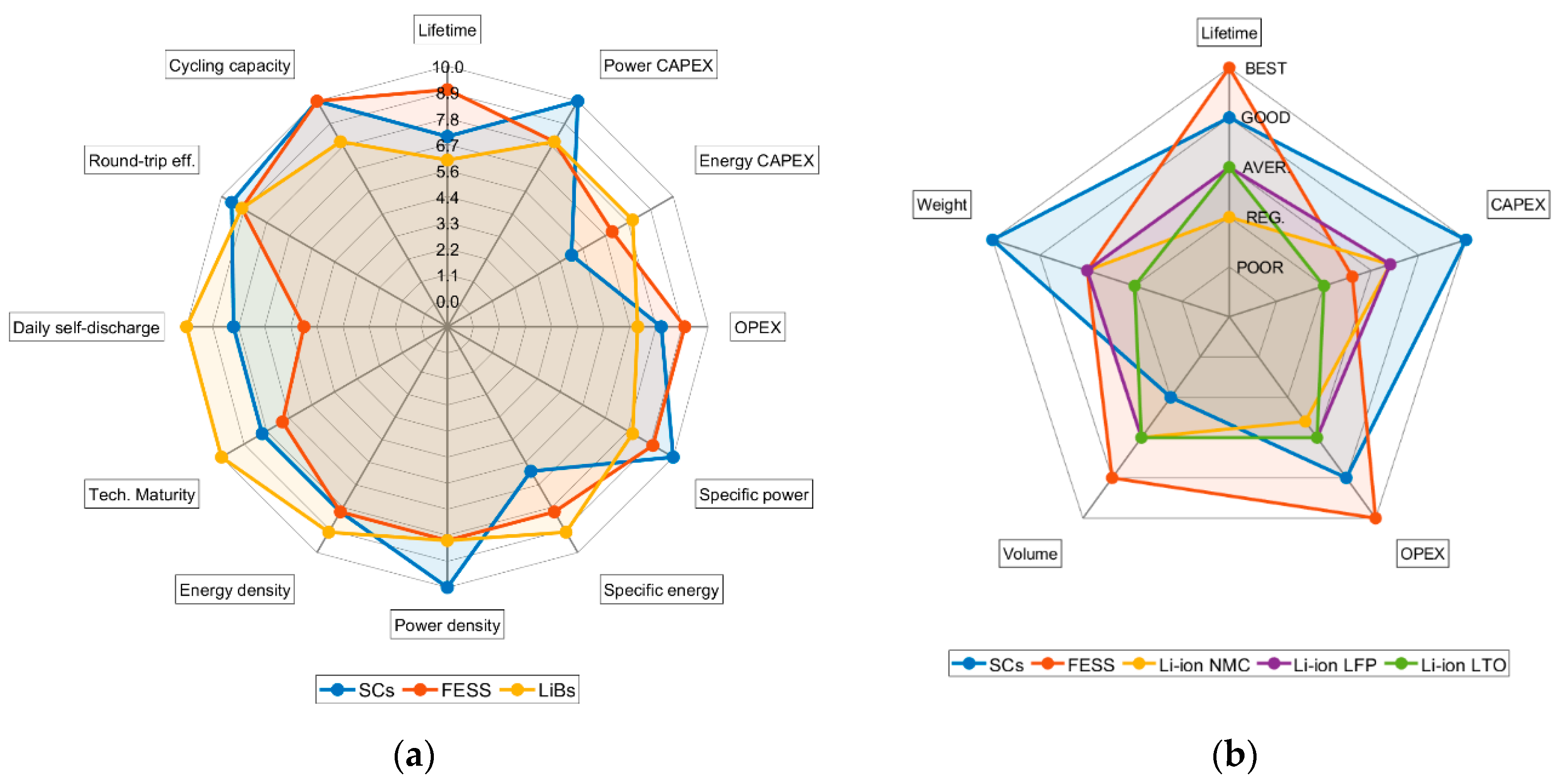
6. Comparison among ESS Alternatives

It is not always straightforward to compare different ES technologies. In this case, the analysis is performed taking into account certain restrictions associated with the given ESS application (wind turbines or wind farms with IR and FS services) that could tailor the election or somehow modify/enhance/minimize the merits of a given ESS solution. In this sense, three different parameters are analyzed: physical constraints (volume and weight), expected lifetime, and cost. In order to reinforce the comparison among ESS technologies in this multi-criteria assessment, Figure 7 is introduced. It represents on the one hand a comparative summary of the main techno-economic characteristics of the candidate technologies. On the other hand, it compares for a given case study (Case 2 in Table 1) the cited constraining or decision parameters/indicators that determine the ESS selection for the application introduced in this work.

6.1. Comparing Weight and Volume

With regard to the physical constraints, an ESS installed in an onshore wind farm can be located anywhere without volume/weight restriction. Usually, it would be placed at the medium-to-high voltage substation where free space should be available. However, for the case of offshore wind farms, volume and weight become an issue and both should be minimized. This is also the case for the analysis of the ESS to be installed in a WT (both on- and off-shore), especially if the nacelle is considered as the potential place to shelter the ESS. Taking Case 2 in Table 1 as reference for comparison, when analyzing commercial solutions of SCs and FESSs, the volume required is similar for the SCs from Maxwell Technologies (Electronic Shock Absorber (ESA), [63]), or FREQCOM (Ultracapacitor Grid Stabilizer (UGS), [64]) and the FESS from Gyrotricity [65]. All of them are, or could be, distributed within a 10-foot shipping container. Note that the FESS itself only occupies a volume of around 2 m3 but the rest of the container is required for the power electronics equipment, the protection devices, etc. Regarding the weight, although no specific data is provided in the datasheets, the FESS would be assumed to be much heavier than SC solutions. However, the Gyrotricity FESS model that would meet the requirements of Case 2 could weigh around 1–1.2 tonnes, which should not be critical at the WT nacelle where many more tonnes of equipment are already harbored. When LiBs are introduced in the comparison, the three selected chemistries for this application (LFP, LTO, and NMC) present quite different properties, as seen from Figure 6. While LFP and LTO present higher specific power, making them appropriate for intensive power demanding applications, they present very poor specific energy (around 120 and 80 Wh/kg, respectively). Conversely, NMC technology does not fit in terms of specific power but presents specific energy up to 200 Wh/kg. This makes NMC solution much lighter and more compact, which is an advantage if placed at the nacelle, though not so much at the wind farm level. In summary, a NMC LiB meeting the power and energy capacity requirements of Case 2 would also weigh, including all the equipment required (power electronics, protections, etc.), between 1 and 1.5 tonnes, with the battery pack size of around 2–2.5 m3 [66]. Solutions with LTO or LFP would therefore be 50% heavier and larger.

6.2. Comparing Lifetime

Regarding the second parameter, similarities can be found when comparing the expected lifetime for SCs and LiBs. For the latter, multiple models are provided in the literature to predict their life expectancy [68,69] using different approaches devoted to the various chemistries. Most models agree that there are temporal (calendar) ageing mechanisms and use (cycle) ageing mechanisms. More precisely, temperature and state-of-charge (SOC) drive the calendar degradation, when the battery is in stand-by mode. The number of cycles that the battery undergoes and the pattern these cycles present (depth of discharge and average SOC), together with the charge to discharge current ratio (C-rate) and temperature are the main factors driving the cycle degradation [70]. At present time, most LiBs are meant to work at around 20 °C, losing capacity at an accelerated pace when operated above 30 °C or below 10 °C. Most applications involving LiBs need active refrigeration type cooling/heating systems. This is also true for SCs that present an accelerated ageing due to temperature when operated above 35–40 °C (despite manufacturers stating an operational range of −45 °C to 60 °C) [69]. While the different types of LiBs are designed to withstand 4000–6000 full cycles (NMC models) or even 8000–10,000 full cycles (LFP or LTO) over a 10-year period, SCs do not present any limitation in terms of cycling. In fact, these are marketed with more than 500 k full cycles due to the physical mechanism they store and deliver the energy with. According to all these conditions, the estimated lifetime for LiBs is very dependent on the function and is usually defined between 5 and 15 years while it can be estimated to be around 10–15 years for SCs [71].
FESSs present a wide temperature operating range defined from −40 to 50 °C within which the systems do not require any external or environmental heating/cooling. Since they are robust throughout the temperature range, they do not suffer substantially from calendar ageing. Nonetheless, the motor-generator used with the flywheel should be water-cooled when power is extracted to ambient air at or above 45–50 °C. In any case, the power electronics are likely to be limited by temperature before the flywheel itself. As FESSs are not limited by cycles their estimated lifetime is around 15–20 years.

6.3. Comparing Cost

Prices regarding ES technologies are difficult to obtain. However, from the different reports [22] and reviews [72,73,74] published in the literature, a reference framework of prices is settled hereon.
FESS is the most difficult technology to quantify in terms of cost, given the low degree of commercial competitors in the market. Information obtained from manufactures indicates that these solutions present multiple expensive components that, beyond the flywheel materials themselves, push the initial CAPEX of the systems (including the interconnection power electronics) up to around 500 €/kW and 6000 €/kWh. This would lead to a 150 k€ FESS for the Case 2 defined requirements. On the other hand, the robustness of this technology makes it the lowest OPEX among the three alternatives.
According to manufacturers, the CAPEX for the different packs of SCs in rack configurations depends on how optimized and accurate the design of the system is, and the number of packs used. Hence, CAPEX can range from 57 to 200 €/kW in power and from 37 to 150 k€/kWh in energy. Thus, it is clearly a power dedicated solution that skyrockets in price when significant energy capacity is required. For the Case 2 under analysis, the overall cost of the SC-based solution could be around 35 k€, according to different commercial models (only considering the SCs) from some of the manufacturers. The OPEX of this technology is, depending on the source, slightly higher or lower than that of the FESS but is clearly lower than that of LiBs since fewer replacements are required during the service life of the system.
The cost of LiBs is widely monitored by different agencies and organizations [72] and has been reviewed and analyzed by different authors. In fact, the descending trend of the LiBs’ cost is the main driver for the increasing global interest on the ES industry. A sustained 21% reduction has been observed every time the global production was doubled [22,75]. As the CAPEX varies significantly among different chemistries so do the cost figures in the different reports that refer to different technologies (Figure 6). While NMC technology may be around 180–450 €/kWh, prices for LFP are around 350–550 €/kWh, and LTO ranges between 850 and 1200 €/kWh. However, since energy capacity requirements are normally prevalent over power capacity requirements in battery applications, limited information is available in terms of €/kW for the different chemistries. In this sense, a BESS mainly limits its power exchange capability through the interconnected power converter. Hence, installation costs range from 200 to 850 €/kW. These prices and the power requirements imply that the battery required to provide IR and FS to the wind turbine in Case 2 would present a CAPEX ranging from 60 k€ to around 250 k€.

6.4. Final Discussion

Attending the previous considerations and the representation introduced in Figure 7 for the case study, some conclusions are drawn. To begin with, the analysis of the physical properties returns similar volume constraints for each of the technology solutions in Case 2. Moreover, although FESS are heavier than SCs, LFP and LTO battery chemistries are the heaviest. Nonetheless, according to the deduced weights, it should not prevent any of them from being installed, even in the nacelle.
The lifetime comparison results vary to those in weight. FESSs have the longest lifespan and are robust to environmental conditions making them suitable for the application. On the contrary, both SCs and LiBs require cooling to avoid accelerated calendar ageing if installed in a nacelle. Cycle ageing is unlikely to affect LiBs for IR supposing this service remains rare. However, this may change in the coming years with the reduction of grid strength and increased penetration of non-dispatchable renewable power sources, as highlighted in [46] and Figure 8. This analysis projects the progressive increase of extreme frequency events as the degree of wind penetration increases in a weak system such as Ireland. Then, cycle ageing could gain importance in the coming future in this application as a consequence of the high C-rate expected to be experienced by the LiBs during the initial response of the system. Additionally, the very important stress factor for cycle ageing of LiBs associated with the depth-of-discharge of the cycles experienced due to the IR service but especially for the FS and primary frequency control services will be a factor to consider and analyze.
With regard to the cost of the different solutions, both CAPEX and OPEX need to be taken into account. LiBs, excluding LTO, are cheaper than FESS. However, LiBs will need to be replaced at regular intervals, probably two to four times in the standard 25 year expected life of a wind turbine. The additional battery costs over the life of the project can offset the higher initial cost of FESS, which have a significant advantage over the projected service life and offer rough parity when OPEX and CAPEX costs are considered. SCs do not require as many replacements as LiBs and have cheaper CAPEX but more expensive OPEX than FESSs. Thus, SCs are probably the cheapest solution if an optimized design can be achieved with standard commercial packs and only a small inertia (H, in seconds) is required. Large inertia requirements and the provision of primary frequency response by the ESS will drive the cost of SCs up meaning solutions with LiBs or FESSs should be considered.

7. Conclusions

After analyzing the power and energy capacity requirements for an ESS implemented at a wind turbine or at a wind farm level to provide IR and FS services, this paper reviewed and discussed the different technologies available in the industry that could comply with these requirements. As well as identifying prospective storage technologies, two control strategies were identified that are capable of providing the specific inertial response characteristics, but may require further adjustment depending on the final technology choice e.g., considering state-of-charge of the storage system. Out of the multiple ES technologies compelled in the literature and taking into account various constraints (location-dependence, maturity, technical characteristics), three are considered as potential candidates: flywheels, supercapacitors, and three chemistries out of the Li-ion battery family (NMC, LFP, and LTO). The three technologies are then described and evaluated from a technological and industrial point of view. Finally, they are compared in terms of physical constraints (volume and weight), expected lifetime, and cost. For such a specific application, none of them are found to be clearly superior to the others and commercial systems will have to be optimally adapted and tailored to the different requirements dependent on the amount of inertia, maximum RoCoF, and maximum frequency deviation to be allowed. It is also important to take into account if the energy storage system is only used for IR service or also for FS or even primary frequency control. In the first case, the high power intensive requirement indicates SC solutions to be the most suitable technology while, in the latter cases, both LiBs and FESSs are superior to SCs.

8. Future Work

The authors would like to discuss future research lines related to the work presented in this paper. In this sense, it is to point out the recent attention gained among researchers by hybrid wind and solar PV installations [77]. Complementary behaviors between wind and solar resources have been observed in different geographical locations, times of the day, and seasons [78]. This opens the door to the arising of hybrid renewable power stations with extended potential capabilities mainly due to a reduced resource intermittency and uncertainty. However, even though hybrid solutions will provide a more constant power output, these might still require the integration of some ESS whose size will vary from that required to complement solar PV or wind installations on their own. Additionally, although the power and energy capacity of the ES required to provide IR and FS will still be mainly depending on the market structure, the optimization of the operation of the hybrid power station while providing these services represents a very interesting research line.

Author Contributions

Conceptualization, A.E.-À., H.B. and L.X.; methodology, H.B., A.E.-À.; software, H.B. and S.H.; validation, H.B., A.E.-À., and S.H.; formal analysis, H.B., A.E.-À., and S.H.; investigation, H.B., A.E.-À., and S.H.; resources, H.B., A.E.-À., and S.H.; data curation, H.B., and S.H.; writing—original draft preparation, H.B. and S.H.; writing—review and editing, A.E.-À., H.B., S.H. and L.X.; visualization, S.H., and H.B.; supervision, H.B., A.E.-À. and L.X.; project administration, H.B., L.X. and A.E.À.; funding acquisition, H.B., L.X. and A.E.-À. All authors have read and agreed to the published version of the manuscript.

Funding

The authors would like to thank the Ministerio de Ciencia, Innovación y Universidades, financing this research by means of project DPI 2017-84503-R, and the Generalitat Valenciana for their financial support via the projects with codes GV-2019-087 and BEST/2018/152, respectively. This work has been also partially funded by the EPSRC grant EP/L016680/1.

Acknowledgments

We thank our colleagues Keith R. Pullen (City University of London) and Pádraig Daly (EirGrid) who provided insight and expertise that greatly assisted the research.

Conflicts of Interest

The authors declare no conflict of interest.

Abbreviations

EUEuropean Union
IRInertial response
UCTEUnion for the co-ordination of transmission of electricity
FSFrequency support
PVCCIPower voltage current control for inertia emulation
VSMVirtual synchronous machine
WTWind turbine
FFRFast frequency response
PLLPhase locked loop
ESSEnergy storage system
RoCoFRate of Change of Frequency
UKUnited Kingdom
ENTSO-EEuropean Network of Transmission System Operators
DCDirect current
ACAlternating current
DFIGDoubly-fed induction generator
BESSBattery energy storage system
SCSupercapacitor
FESS Flywheel energy storage system
LiBLithium-ion battery
SMESSuperconducting magnetic energy storage
CAES Compressed-air energy storage
HICHybrid ion capacitors
LALead-acid batteries
NaSSodium sulphur batteries
UCUltracapacitor
SOCState of charge
SOHState of health
UPSUninterruptible power supply
VRSVoltage restorer systems
LCOLithium cobalt oxide
LFP Lithium iron phosphate
NCALithium nickel cobalt aluminum oxide
LMOLithium manganese oxide
NMCLithium nickel manganese cobalt oxide
LTOLithium titanate
CAPEXCapital expenditure
OPEXOperational expenditure

References

  1. Wind Europe. Wind energy in Europe in 2018; Wind Europe: Brussels, Belgium, 2018. [Google Scholar]
  2. Milano, F.; Dörfler, F.; Hug, G.; Hill, D.J.; Verbič, G. Foundations and Challenges of Low-Inertia Systems (Invited Paper). In Proceedings of the 2018 Power Systems Computation Conference (PSCC), Dublin, ‎Ireland, 11 June 2018; pp. 1–25. [Google Scholar] [CrossRef] [Green Version]
  3. National Grid ESO. Operability Strategy Report; National Grid ESO: Warwick, UK, 2019. [Google Scholar]
  4. Teng, F.; Mu, Y.; Jia, H.; Wu, J.; Zeng, P.; Strbac, G. Challenges on primary frequency control and potential solution from EVs in the future GB electricity system. Appl. Energy 2017, 194, 353–362. [Google Scholar] [CrossRef]
  5. O’Sullivan, J.; Rogers, A.; Flynn, D.; Smith, P.; Mullane, A.; O’Malley, M. Studying the Maximum Instantaneous Non-Synchronous Generation in an Island System—Frequency Stability Challenges in Ireland. IEEE Trans. Power Syst. 2014, 29, 2943–2951. [Google Scholar] [CrossRef] [Green Version]
  6. Kundur, P. Power System Stability and Control; McGraw-Hill Education: New York, NY, USA, 1995. [Google Scholar]
  7. Kerdphol, T.; Rahman, F.S.; Mitani, Y. Virtual Inertia Control Application to Enhance Frequency Stability of Interconnected Power Systems with High Renewable Energy Penetration. Energies 2018, 11, 981. [Google Scholar] [CrossRef] [Green Version]
  8. García-Ruiz, M.; Cantos-Alcántara, G.J.; Martínez-Ramos, J.L.; Marano-Marcolini, A. Minimum Required Inertia for a Fully Renewable AC Interconnected System. In Proceedings of the International Conference on Smart Energy Systems and Technologies (SEST), Porto, Portugal, 9 September 2019. [Google Scholar]
  9. Nguyen, H.T.; Yang, G.; Nielsen, A.H.; Jensen, P.H. Frequency stability improvement of low inertia systems using synchronous condensers. In Proceedings of the 2016 IEEE International Conference Smart Grid Commun. SmartGridComm, Sydney, Australia, 6 November 2016; pp. 650–655. [Google Scholar] [CrossRef]
  10. Gu, H.; Yan, R.; Saha, T.K. Minimum Synchronous Inertia Requirement of Renewable Power Systems. IEEE Trans. Power Syst. 2018, 33, 1533–1543. [Google Scholar] [CrossRef] [Green Version]
  11. Dreidy, M.; Mokhlis, H.; Mekhilef, S. Inertia response and frequency control techniques for renewable energy sources: A review. Renew. Sustain. Energy Rev. 2017, 69, 144–155. [Google Scholar] [CrossRef]
  12. Guan, M.; Pan, W.; Zhang, J.; Hao, Q.; Cheng, J.; Zheng, X. Synchronous Generator Emulation Control Strategy for Voltage Source Converter (VSC) Stations. IEEE Trans. Power Syst. 2015, 30, 1–9. [Google Scholar] [CrossRef]
  13. Miller, N.; Lew, D.; Piwko, R. Technology capabilities for fast frequency response. GE Energy Consulting, Tech. Rep 3; Australian Energy Market Operator: Melbourne, Australia, 2017. [Google Scholar]
  14. Morren, J.; De Haan, S.; Kling, W.L.; Ferreira, J. Wind Turbines Emulating Inertia and Supporting Primary Frequency Control. IEEE Trans. Power Syst. 2006, 21, 433–434. [Google Scholar] [CrossRef]
  15. Morren, J.; Pierik, J.; De Haan, S.W. Inertial response of variable speed wind turbines. Electr. Power Syst. Res. 2006, 76, 980–987. [Google Scholar] [CrossRef]
  16. Zhong, Q.-C.; Weiss, G. Synchronverters: Inverters That Mimic Synchronous Generators. IEEE Trans. Ind. Electron. 2010, 58, 1259–1267. [Google Scholar] [CrossRef]
  17. Henderson, C.; Vozikis, D.; Holliday, D.; Bian, X.; Egea-Àlvarez, A. Assessment of Grid-Connected Wind Turbines with an Inertia Response by Considering Internal Dynamics. Energies 2020, 13, 1038. [Google Scholar] [CrossRef] [Green Version]
  18. Sun, C.; Ali, S.Q.; Joos, G.; Bouffard, F. Virtual Synchronous Machine Control for Low-Inertia Power System Considering Energy Storage Limitation. In Proceedings of the ECCE 2019. IEEE Energy Conversion Congress & Expo, Baltimore, MD, USA, 29 September–3 October 2019. [Google Scholar] [CrossRef]
  19. Ma, Y.; Lin, Z.; Yu, R.; Zhao, S. Research on Improved VSG Control Algorithm Based on Capacity-Limited Energy Storage System. Energies 2018, 11, 677. [Google Scholar] [CrossRef] [Green Version]
  20. Arani, M.F.M.; El-Saadany, E.F. Implementing Virtual Inertia in DFIG-Based Wind Power Generation. IEEE Trans. Power Syst. 2012, 28, 1373–1384. [Google Scholar] [CrossRef]
  21. Fang, J.; Tang, Y.; Li, H.; Li, X. A Battery/Ultracapacitor Hybrid Energy Storage System for Implementing the Power Management of Virtual Synchronous Generators. IEEE Trans. Power Electron. 2018, 33, 2820–2824. [Google Scholar] [CrossRef]
  22. Schmidt, O.; Hawkes, A.D.; Gambhir, A.; Staffell, I. The future cost of electrical energy storage based on experience rates. Nat. Energy 2017, 2, 17110. [Google Scholar] [CrossRef]
  23. Fu, Y.; Wang, Y.; Zhang, X. Integrated wind turbine controller with virtual inertia and primary frequency responses for grid dynamic frequency support. IET Renew. Power Gener. 2017, 11, 1129–1137. [Google Scholar] [CrossRef]
  24. Ochoa, D.; Martínez, S.; Ochoa, D. Fast-Frequency Response Provided by DFIG-Wind Turbines and its Impact on the Grid. IEEE Trans. Power Syst. 2017, 32, 4002–4011. [Google Scholar] [CrossRef]
  25. D’Arco, S.; Suul, J.A.; Fosso, O.B. A Virtual Synchronous Machine implementation for distributed control of power converters in SmartGrids. Electr. Power Syst. Res. 2015, 122, 180–197. [Google Scholar] [CrossRef]
  26. Alsiraji, H.A.; El-Shatshat, R. Comprehensive assessment of virtual synchronous machine based voltage source converter controllers. IET Gener. Transm. Distrib. 2017, 11, 1762–1769. [Google Scholar] [CrossRef]
  27. Heydari, R.; Savaghebi, M.; Blaabjerg, F. Fast Frequency Control of Low-Inertia Hybrid Grid Utilizing Extended Virtual Synchronous Machine. In Proceedings of the 2020 11th Power Electronics, Drive Systems, and Technologies Conference (PEDSTC), Tehran, Iran, 4 February 2020. [Google Scholar] [CrossRef]
  28. Asensio, A.P.; Gonzalez-Longatt, F.; Arnaltes, S.; Rodriguez-Amenedo, J.L. Analysis of the Converter Synchronizing Method for the Contribution of Battery Energy Storage Systems to Inertia Emulation. Energies 2020, 13, 1478. [Google Scholar] [CrossRef] [Green Version]
  29. Yap, K.Y.; Sarimuthu, C.R.; Lim, J.M.-Y. Virtual Inertia-Based Inverters for Mitigating Frequency Instability in Grid-Connected Renewable Energy System: A Review. Appl. Sci. 2019, 9, 5300. [Google Scholar] [CrossRef] [Green Version]
  30. Ma, Y.; Cao, W.; Yang, L.; Wang, F.F.; Tolbert, L.M. Virtual Synchronous Generator Control of Full Converter Wind Turbines With Short-Term Energy Storage. IEEE Trans. Ind. Electron. 2017, 64, 8821–8831. [Google Scholar] [CrossRef]
  31. Liu, J.; Wen, J.; Long, Y.; Yao, W. Solution to short-term frequency response of wind farms by using energy storage systems. IET Renew. Power Gener. 2016, 10, 669–678. [Google Scholar] [CrossRef]
  32. Datta, U.; Kalam, A.; Shi, J. Battery Energy Storage System for Aggregated Inertia-Droop Control and a Novel Frequency Dependent State-of-Charge Recovery. Energies 2020, 13, 2003. [Google Scholar] [CrossRef] [Green Version]
  33. Othman, M.H.; Mokhlis, H.; Mubin, M.; Talpur, S.; Ab Aziz, N.F.; Dradi, M.; Mohamad, H. Progress in control and coordination of energy storage system-based VSG: A review. IET Renew. Power Gener. 2020, 14, 177–187. [Google Scholar] [CrossRef]
  34. Tamura, S. Economic Analysis of Hybrid Battery Energy Storage Systems Applied to Frequency Control in Power System. Electr. Eng. Jpn. 2015, 195, 24–31. [Google Scholar] [CrossRef]
  35. Atherton, J.; Sharma, R.; Salgado, J. Techno-economic analysis of energy storage systems for application in wind farms. Energy 2017, 135, 540–552. [Google Scholar] [CrossRef] [Green Version]
  36. Li, C. Techno-economic study of off-grid hybrid photovoltaic/battery and photovoltaic/battery/fuel cell power systems in Kunming, China. Energy Sources Part A Recover. Util. Environ. Eff. 2018, 41, 1588–1604. [Google Scholar] [CrossRef]
  37. Vaca, S.M.; Patsios, C.; Taylor, P. Enhancing frequency response of wind farms using hybrid energy storage systems. In Proceedings of the 2016 IEEE International Conference on Renewable Energy Research and Applications (ICRERA), Birmingham, Germany, 20 November 2016; pp. 325–329. [Google Scholar] [CrossRef] [Green Version]
  38. Chong, L.W.; Wong, Y.W.; Rajkumar, R.K.; Rajkumar, R.K.; Isa, D. Hybrid energy storage systems and control strategies for stand-alone renewable energy power systems. Renew. Sustain. Energy Rev. 2016, 66, 174–189. [Google Scholar] [CrossRef]
  39. Hajiaghasi, S.; Salemnia, A.; Hamzeh, M. Hybrid energy storage system for microgrids applications: A review. J. Energy Storage 2019, 21, 543–570. [Google Scholar] [CrossRef]
  40. Albu, M.; Visscher, K.; Creanga, D.; Nechifor, A.; Golovanov, N. Storage selection for DG applications containing Virtual Synchronous Generators. In Proceedings of the IEEE Bucharest Power Tech Conference, Bucharest, Romania, 28 June 2009. [Google Scholar]
  41. Akram, U.; Nadarajah, M.; Shah, R.; Milano, F. A review on rapid responsive energy storage technologies for frequency regulation in modern power systems. Renew. Sustain. Energy Rev. 2020, 120, 109626. [Google Scholar] [CrossRef]
  42. Li, J.; Ma, Y.; Mu, G.; Feng, X.; Yan, G.; Guo, G.; Zhang, T. Optimal Configuration of Energy Storage System Coordinating Wind Turbine to Participate Power System Primary Frequency Regulation. Energies 2018, 11, 1396. [Google Scholar] [CrossRef] [Green Version]
  43. Tsili, M.; Papathanassiou, S. A review of grid code technical requirements for wind farms. IET Renew. Power Gener. 2009, 3, 308. [Google Scholar] [CrossRef]
  44. National Grid Electricity System Operator. Available online: https://www.nationalgrideso.com/codes/grid-code (accessed on 31 August 2019).
  45. ENTSO-E. Rate of Change of Frequency (RoCoF) withstand Capability, ENTSO-E Guidance Document for National Implementation for Network Codes on Grid Connection; ENTSO-E: Brussels, Belgium, 2018. [Google Scholar]
  46. Ghofrani, M.; Arabali, A.; Etezadi-Amoli, M.; Fadali, M.S. A Framework for Optimal Placement of Energy Storage Units Within a Power System with High Wind Penetration. IEEE Trans. Sustain. Energy 2013, 4, 434–442. [Google Scholar] [CrossRef]
  47. Styczynski, Z.A. Electric Energy Storage and its tasks in the integration of wide-scale renewable resources. In Proceedings of the Integration of Wide-Scale Renewable Resources into the Power Delivery System, 2009 CIGRE/IEEE PES Joint Symposium, Calgary, AB, Canada, 29 July 2009; pp. 1–11. [Google Scholar]
  48. Hadjipaschalis, I.; Poullikkas, A.; Efthimiou, V. Overview of current and future energy storage technologies for electric power applications. Renew. Sustain. Energy Rev. 2009, 13, 1513–1522. [Google Scholar] [CrossRef]
  49. Hill, C.A.; Such, M.C.; Grady, W.M.; Chen, N.; Gonzalez, J. Battery Energy Storage for Enabling Integration of Distributed Solar Power Generation. IEEE Trans. Smart Grid 2012, 3, 850–857. [Google Scholar] [CrossRef]
  50. Nikolaidis, P.; Poullikkas, A. Cost metrics of electrical energy storage technologies in potential power system operations. Sustain. Energy Technol. Assessments 2018, 25, 43–59. [Google Scholar] [CrossRef]
  51. Luo, X.; Wang, J.; Dooner, M.; Clarke, J. Overview of current development in electrical energy storage technologies and the application potential in power system operation. Appl. Energy 2015, 137, 511–536. [Google Scholar] [CrossRef] [Green Version]
  52. Ali, M.H.; Wu, B.; Dougal, R.A. An Overview of SMES Applications in Power and Energy Systems. IEEE Trans. Sustain. Energy 2010, 1, 38–47. [Google Scholar] [CrossRef]
  53. Ngamroo, I.; Supriyadi, A.C.; Dechanupaprittha, S.; Mitani, Y. Power oscillation suppression by robust SMES in power system with large wind power penetration. Phys. C Supercond. 2009, 469, 44–51. [Google Scholar] [CrossRef]
  54. Lee, S.-S.; Kim, Y.-M.; Park, J.-K.; Moon, S.-I.; Yoon, Y.-T. Compressed Air Energy Storage Units for Power Generation and DSM in Korea. In Proceedings of the Power Engineering Society General Meeting, Tampa, FL, USA, 24 June 2007. [Google Scholar] [CrossRef]
  55. Swider, D.J. Compressed Air Energy Storage in an Electricity System With Significant Wind Power Generation. IEEE Trans. Energy Convers. 2007, 22, 95–102. [Google Scholar] [CrossRef]
  56. Abdon, A.; Zhang, X.; Parra, D.; Patel, M.K.; Bauer, C.; Worlitschek, J. Techno-economic and environmental assessment of stationary electricity storage technologies for different time scales. Energy 2017, 139, 1173–1187. [Google Scholar] [CrossRef]
  57. Ding, J.; Hu, W.; Paek, E.; Mitlin, D. Review of Hybrid Ion Capacitors: From Aqueous to Lithium to Sodium. Chem. Rev. 2018, 118, 6457–6498. [Google Scholar] [CrossRef] [PubMed]
  58. Roberts, B.P. Sodium-Sulfur (NaS) batteries for utility energy storage applications. In Proceedings of the Power and Energy Society General Meeting-Conversion and Delivery of Electrical Energy in the 21st Century, Pittsburgh, PA, USA, 20 July 2008. [Google Scholar] [CrossRef]
  59. Nichols, D.K.; Eckroad, S. Utility-scale application of sodium sulfur battery. In Proceedings of the IEEE International Stationary Battery Conference (Battcon’03), Marco Island, FL, USA, April 2003. [Google Scholar]
  60. Pullen, K. The Status and Future of Flywheel Energy Storage. Joule 2019, 3, 1394–1399. [Google Scholar] [CrossRef]
  61. Amiryar, M.; Pullen, K. A Review of Flywheel Energy Storage System Technologies and Their Applications. Appl. Sci. 2017, 7, 286. [Google Scholar] [CrossRef] [Green Version]
  62. Schneider, D. Silicon anodes will give lithiumion batteries a boost. IEEE Spectr. 2018, 56, 48–49. [Google Scholar] [CrossRef]
  63. Schneuwly, A. Maxwell Technologies White Paper-High Reliability Power Backup with Advanced Energy Storage; Maxwell Technologies, Inc.: San Diego, CA, USA, 2009. [Google Scholar]
  64. FREQCON GmbH. Ultracapacitor Grid Stabilizer. 2018. Available online: https://www.freqcon.com/wp-content/uploads/FREQCON-datasheet-grid-storage-ultracapacitor-grid-stabilizer.pdf (accessed on 7 September 2019).
  65. Pullen, K. Low Cost Flywheel Energy Storage: Supporting the Transformation to Renewables; Energy Institute-London and Home Counties Branch: London, UK, 2017; pp. 1–15. [Google Scholar]
  66. Chem, L.G. Global Catalog 2018. Available online: http://m.lgchem.com/upload/file/product/LGChem_Catalog_Global_2018.pdf (accessed on 7 September 2019).
  67. Moses 2020. Spider_Plot. Available online: https://www.github.com/NewGuy012/spider_plot (accessed on 13 June 2020).
  68. Barré, A.; Deguilhem, B.; Grolleau, S.; Gerard, M.; Suard, F.; Riu, D. A review on lithium-ion battery ageing mechanisms and estimations for automotive applications. J. Power Sources 2013, 241, 680–689. [Google Scholar] [CrossRef] [Green Version]
  69. Berecibar, M.; Gandiaga, I.; Villarreal, I.; Omar, N.; Van Mierlo, J.; Bossche, P.V.D. Critical review of state of health estimation methods of Li-ion batteries for real applications. Renew. Sustain. Energy Rev. 2016, 56, 572–587. [Google Scholar] [CrossRef]
  70. Beltran, H.; Garcia, I.T.; Alfonso-Gil, J.C.; Pérez, E.; Alfonso, J.C. Levelized Cost of Storage for Li-Ion Batteries Used in PV Power Plants for Ramp-Rate Control. IEEE Trans. Energy Convers. 2019, 34, 554–561. [Google Scholar] [CrossRef]
  71. El Brouji, E.-H.; Briat, O.; Vinassa, J.-M.; Bertrand, N.; Woirgard, E. Impact of Calendar Life and Cycling Ageing on Supercapacitor Performance. IEEE Trans. Veh. Technol. 2009, 58, 3917–3929. [Google Scholar] [CrossRef]
  72. D’Aprile, P.; Newman, J.; Pinner, D. The New Economics of Energy Storage; McKinsey & Co.: New York, NY, USA, 2016. [Google Scholar]
  73. International Renewable Energy Agency (IRENA). Electricity Storage And Renewables: Costs And Markets to 2030; International Renewable Energy Agency (IRENA): Abu Dhabi, UAE, 2017. [Google Scholar]
  74. Schmidt, O.; Melchior, S.; Hawkes, A.; Staffell, I. Projecting the future levelized cost of electricity storage technologies. Joule 2019, 3, 81–100. [Google Scholar] [CrossRef] [Green Version]
  75. Liebreich, M. Keynote-Bloomberg New Energy Finance Summit 2016; Bloomberg New Energy Finance: London, UK, 2016. [Google Scholar]
  76. Daly, P. Power System Inertia: Challenges & Solutions; Engineers Ireland: Dublin, Ireland, 2016. [Google Scholar]
  77. Jurasz, J.; Canales, F.A.; Kies, A.; Guezgouz, M.; Beluco, A. A review on the complementarity of renewable energy sources: Concept, metrics, application and future research directions. Solar Energy 2020, 195, 703–724. [Google Scholar] [CrossRef]
  78. Gallardo, R.P.; Ríos, A.M.; Ramírez, J.S. Analysis of the solar and wind energetic complementarity in Mexico. J. Clean. Prod. 2020, 268. [Google Scholar] [CrossRef]
Figure 1. Frequency regulation services and markets according to the System Operability Framework 2016 from National Grid when the frequency is below nominal [3].
Energies 13 03421 g001
Figure 2. Considered locations for the EES at wind turbine (purple) and wind farm (green) level.
Energies 13 03421 g002
Figure 3. Control schemes for the (a) PVCCI strategy and (b) VSM control strategy.
Energies 13 03421 g003aEnergies 13 03421 g003b
Figure 4. Inertial responses of the two control types. (a,c and e) show the PVCCI-controlled response and (b,d and f) show the VSM controlled responses for study Cases 1–3 respectively.
Energies 13 03421 g004
Figure 5. Superposition of power and energy requirements at turbine (blue) and wind farm level (green) for IR over power and rated energy capacity for ESS technologies [51].
Energies 13 03421 g005
Figure 6. Technical comparison of the main characteristics among the six commercial lithium ion chemistries.
Energies 13 03421 g006
Figure 7. Spider plot comparison of the (a) potential characteristics of the candidate ESS technologies and (b) constraining indicators that determine the ESS selection for IR and FS in Case 2 (Table 1). Represented with [67].
Energies 13 03421 g007
Figure 8. Estimated impact of lower inertia on system frequency response for Ireland [76].
Energies 13 03421 g008
Table 1. Power and energy requirements at a wind turbine level.
Sn (MW)H (s)RoCoF (Hz/s)Maximum Frequency Deviation (Hz)Inertia Response Required Power (kW)Inertia Response Required Energy (kWh)Frequency Support for 10 s (kWh)
Case 1310.51600.030.17
Case 2312.513000.030.83
Case 3380.514800.271.33
Case 4382.5124000.276.67
Case 5310.55600.170.17
Case 6312.553000.170.83
Case 7380.554801.331.33
Case 8382.5524001.336.67
Table 2. Power and energy requirements at a wind farm level.
Sn (MW)H (s)RoCoF (Hz/s)Maximum Frequency Deviation (Hz)Inertia Response Required Power (MW)Inertia Response Required Energy (kWh)Frequency Support for 10 s (kWh)
Case 950110.51105.5527.78
Case 1050112.51505.55138.89
Case 1150180.518044.44222.22
Case 1250182.5140044.441111.1
Case 1350110.551027.7727.78
Case 1450112.555027.77138.89
Case 1550180.5580222.22222.22
Case 1650182.55400222.221111.1
Table 3. Inertial requirements and controller parameters for Cases 1–3.
H (s)Pstorage (kW) k i n k d N k p V S M k i V S M
Case 116019,3051166.66 3.564 · 10 6 5.224 · 10 5
Case 2130020,2701166.66 2.192 · 10 6   1.047 · 10 5
Case 38480154,6441166.66 1.371 · 10 6 6.547 · 10 6
Table 4. Energy delivered for inertial response (kWh).
P V C C I V S M
Case 10.03310.0334
Case 20.03480.0334
Case 30.26430.2666

