Article

The Two-Phase Conical Swirl Atomizers: Spray Characteristics

by
Marek Ochowiak
1,*,
Andżelika Krupińska
1,
Sylwia Włodarczak
1,
Magdalena Matuszak
1,
Małgorzata Markowska
1,
Marcin Janczarek
1 and
Tomasz Szulc
2
1
Department of Chemical Engineering and Equipment, Poznan University of Technology, 60-965 Poznan, Poland
2
Industrial Institute of Agricultural Engineering, Łukasiewicz Research Network, 60-963 Poznan, Poland
*
Author to whom correspondence should be addressed.
Energies 2020, 13(13), 3416; https://doi.org/10.3390/en13133416
Submission received: 20 April 2020 / Revised: 15 June 2020 / Accepted: 28 June 2020 / Published: 2 July 2020

Abstract

:
This paper presents the results of experimental studies on two-phase conical swirl atomizers. The impact of various atomizer geometries and different operational parameters of the atomization process on the spray characteristics was investigated. The influence of the mixing chamber height HS to diameter DS ratio and the volumetric flow rates of liquid and gas on the discharge coefficient values, spray angle, droplet size expressed by Sauter mean diameter D32, volumetric and radial distributions of droplet diameters in the spray stream were determined. The analysis of results showed that the discharge coefficient values depend on the Reynolds number for liquid and gas and the atomizer geometry. The spray angle increases as the flow rate of liquid and gas increases depending on the applied atomizer construction. The Sauter mean diameter value is correlated with the geometric dimensions of the atomizer swirl chamber. The rapid increase in D32 occurs after exceeding the value HS/DS 3. The Sauter mean diameter also depends on the operating parameters. A central area of stream is filled with smaller sized droplets as the gas flow rate increases.

1. Introduction

The atomization of liquids is an important and interesting large-scale process used in many industries [1,2]. Its application concerns, among others, fields of the economy such as agrotechnics, energy engineering, machine industry, transport and communication, chemical engineering and environmental protection. This process involves a stream of liquid transformation into small droplets, which increases the surface to volume ratio. Atomization is mainly applied to increase the liquid surface and intensify the heat and mass exchange processes between the liquid and gas phases [3]. This process requires the use of external energy to overcome surface tension forces, which can be performed in various ways: using gas energy or ultrasound, mechanically or electrically [4,5,6,7]. A particularly interesting case is atomization carried out in two-phase atomizers with a swirled flow [8]. For proper usage of atomized liquid, its movement has to be done intentionally. It is expected that the formed atomized liquid will be characterized by droplets with desired diameters, a uniform droplet distribution and a defined range and spray angle [7]. Agricultural atomizing involves the aspect of plant care and protection. It is one of the key stages determining the possibility of obtaining abundant crops of satisfactory quality [9,10]. It is particularly important to focus the treatment on a specific goal and reduce the losses of the applied agents. Liquid chemical application should be carried out in accordance with the precise techniques of plant protection, keeping the standards of high-performance pesticide technology, which means providing the active substance in the right place, in sufficient quantity and in the right form [11]. Obtaining a spray with specific characteristics is necessary to achieve the intended efficiency, while maintaining ecological and economic considerations. One of the most important problems encountered when applying plant protection products is the issue of spray drift due to the wind. In order to limit this negative phenomenon, a number of guidelines have been introduced to allow specific procedures to be carried out under given atmospheric conditions. In addition, there are efforts to reduce the number of droplets with the smallest size (called satellite droplets). This effect can be obtained by modifying the composition of the solution to be atomized and by choosing the appropriate atomizers and their work regimes [12,13]. Another important issue is the equability of the applied spraying, and consequently the coverage of objects being sprayed [14].
Two-phase atomizers with a swirled flow are characterized by high efficiency and reliability, while maintaining a simple construction. They can obtain a spray with smaller size droplets and better spray quality in comparison to classic single-phase atomizers. They also show a low sensitivity to atomized liquid rheological properties and a change in the range of process parameters. This allows for a wider application field, while maintaining the economic aspect. An additional second gas phase makes the atomization of a liquid possible in a controlled and effective way [7,15,16]. All these features allow their use in the agriculture sector, dealing with horticulture, grapevine and vegetable cultivation.
The basic parameters describing the spray stream are, among others, pressure drop at the atomizer, the liquid discharge coefficient, the spray angle, distribution of droplet diameters and the mean droplet diameters.
The discharge coefficient can be defined as the ratio of actual mass flow rate to the ideal mass flow rate through the atomizer orifice [17,18]. This is an important performance parameter describing the flow of liquid, that is crucial when designing atomizers [19,20]. The values of discharge coefficient can be determined from the formula
C D = w L · ρ L ( 2 ρ L · P ) 0.5
where wL—flow velocity of liquid through the atomizer; ρL—density of liquid; ∆P—pressure drop measured at the inlet.
In the literature, there are many empirical and semi-empirical correlation equations describing a value of discharge coefficient, such as those proposed by Jedelsky and Jicha [21], Lee and co-workers [22] or Ochowiak [23]. The developed dependence by Jedelsky and Jicha [21] was based on previous literature reports and on experimental tests carried out for over 30 atomizers. It can predict and estimate the discharge coefficient with an accuracy of no less than ±10%. The presented formula considers the influence of liquid and gas properties, atomizer geometry and operating parameters on the value of discharge coefficient [21]. This correlation was presented as
C D = 0.62 ( η L η w a t e r ) 0.04 ( σ L σ w a t e r ) 0.02 ( l 0 d 0 sin ( 2 β ) 0.5 ) 0.11 · M L ˙ A 0 ( 2 ρ L P ) 0.5 1 ( 1 + G L R )
The value of discharge coefficient depends on the pressure losses occurring in an atomizer [24]. Most often, the value of discharge coefficient is given as a function of the dimensionless Reynolds number defined for Newtonian fluids as [25]
R e = w · d 0 · ρ η
where d0—characteristic dimension (diameter of the atomizer orifice), η—viscosity of fluid (L–liquid, G—gas).
Another characteristic dimensionless module used to describe the two-phase atomization process is the ratio of the gas mass flow rate to the liquid mass flow rate, which is shown by the following equation:
G L R = M G ˙ M L ˙
The term ‘spray angle’ is to be understood as the angle formed between two straight lines along the stream flowing out from the atomizer. It is an important performance parameter in the atomization process that determines the total surface coverage with a spray [22]. Broniarz-Press et al. [26] and Ochowiak et al. [27] showed that the spray angle depends on the atomizer dimensions, the properties of liquid, the density of the medium in which atomization occurs and the operating conditions of the atomizer. Gavaises et al. [28] showed that the liquid film thickness and its mean axial and swirl velocity components are very important for CFD predicting parameters of gasoline sprays. Arcoumanis and Gavaises [29] predicted the flow development inside the discharge hole of a pressure-swirl atomizer connected to a common-rail-based fuel injection system for DISI engines. The authors [29] showed the mechanism of liquid film formation inside the injection hole and spray cone angle vs. the swirling motion and geometry of the atomizer.
The mean droplet diameter is an equivalent value, characterizing a collection of homogeneous droplets in place of the actual atomization spectrum. This can evaluate the quality of atomization and determine the droplet properties. One of the main and characteristic diameters is the mean droplet diameter, called the Sauter diameter [2,30]. The Sauter mean diameter is, by definition, the ratio of the third to the second moment of the probability density function [31]
D 32 = d m i n d m a x d 3 p ( d ) d d d m i n d m a x d 2 p ( d ) d d
or for any size distribution of discrete entities
D 32 = i = 1 i = n N i d i 3 i = 1 i = n N i d i 2
The Sauter diameter is very often applied because it allows for the characterization of many important processes, including determining the efficiency and rate of heat and mass transfer [2]. There are equations in the literature for swirl atomizers that can predict the mean droplet diameter. They consider the influence of liquid properties and atomization process conditions [7,32,33,34].
Atomization process characteristics also include the analysis of the internal structure of spray, defined by the distribution of liquid in a spray. This is particularly important due to the selection of the proper atomizer type for a specific application [2,35]. Liu et al. [35] have studied the constructions applicable to the fuel atomization. They showed the necessity of the obtained stream uniformity in order to reach a high combustion efficiency, low emission of pollutants and uniform temperature distribution after leaving the combustion chamber [35]. In the paper by Dumouchel et al. [36], a numerical analysis was carried out of the velocity field throughout a swirl spray atomizer and, more specially, at the orifice. After an examination of the parameters involved in the problem, it was found that the characteristics of the conical liquid sheet produced at the atomizer’s orifice are mainly functions of the geometry of the atomizer. This finding agrees well with a wide range of experimental investigations [37,38,39,40,41].
The atomizer structure itself influences the resulting spray. Rashad et al. [42] conducted the series of experimental studies to demonstrate the effect of atomizer geometry on the spray individual parameters. Twelve atomizers with different geometric configurations were tested, divided by the dimensional variation in the mixing chamber and the orifice. The results showed that the appropriate ratio of the atomizer characteristic dimensions allowed the production a stream with possibly the lowest values of mean droplet diameters and spray angle [42]. Rezaeimoghaddam et al. [37] studied the extensive numerical simulation the effects of changes in the ratio of length to diameter in orifice, and increases in orifice diameter, swirl chamber angle, needle head cone angle and needle lift on the injector performance. The authors showed that the swirl chamber convergence angle has the opposite effect on performance parameters. With an increase in convergence angle, the charge coefficient increase and the spray cone angle decreases. Arcoumanis et al. [38] studied the effect of various atomizer operating arid design parameters, such as the injection and back pressure, the needle lift and the radius of curvature of the discharge hole both at its inlet and exit, on the development of the liquid film and the droplet parcel location. These observations are consistent with the data from the works [39,40,41] and can be helpful, e.g., in the design of agricultural sprayers.
The purpose of this paper is to propose and discuss a modified design solution for atomizers using swirl movement in relation to their potential application primarily in agriculture. The influences of atomizer geometry and operating parameters on the atomization process were also determined. The analyzed variables are the value of the discharge coefficient, spray angle, volumetric and radial distribution of droplet diameters and Sauter mean diameters.

2. Materials and Methods

Figure 1 presents a simplified scheme of the experimental set-up, which consisted of two-phase atomizers using the phenomenon of swirl movement, stainless steel tank, Krohne Messtechnik VA 40 rotameters (Krohne Polska Sp. z o.o., Gdansk, Poland), CHI 2–30 pump from Grunfos Poland (Grunfos Pompy Sp. z o.o., Przezmierowo, Poland), Center 309 digital thermometer (Nokeval, Nokia, Finland), Metabo Mega 350–100D compressor (Metabo Polska Sp. z.o.o., Stargard, Poland), Spraytec analyzer from Malvern Instruments and a computer with SOP software (Standard Operating Procedure Software by Malvern Instruments; Malvern, United Kingdom). The experimental set-up has been specially adapted for the needs of experimental studies. The tested atomizers were placed on a crane traveling along a designated running track of la = 0.842 m, with a constant speed of wa = 0.0495 m/s. The distance between the atomizer orifice and the measuring point was ha = 0.520 m. This solution allowed to examine the nature of the stream and to determine the spray angle.
During the experiments, the tank was filled with water, which was transferred to the liquid rotameter by the pump. The air compressed with the compressor was directed to gas rotameters. The air and water from the rotameters flowed to the atomizer. The swirl atomizers with two inlet ports, with a diameter of dp = 0.0025 m, a length of lp = 0.0055 m, at an angle β = 30° and an orifice with diameter d0 = 0.0025 m, were used (Figure 2). The modification of the design mainly concerned the change in the position of the inlet ports supplying both media. The inlet ports are located tangentially here relative to the swirl chamber, which has the shape of a cone. The diameter of the swirl chamber DS was 0.02 and 0.04 m, and its height HS was equal to 0.02, 0.04, 0.06, 0.07 and 0.08 mm, respectively. The dimensions of the individual atomizers are summarized in Table 1.
The experiments were carried out in the range of gas flow rates from 2.92 × 10⁻⁵ to 6.94 × 10⁻⁴ m3/s and liquids from 1.39 × 10⁻⁶ do 6.94 × 10⁻⁵ m3/s, which equals a value of GLR from 0.0005 to 0.6, in real time, with a linear displacement of 50 mm. The temperature during the experiments was T = 20 ± 1 °C.

3. Results

3.1. Flow Characteristics

To describe the internal flow, the characteristic values of dimensionless Reynolds numbers and the GLR ratio were determined, as shown in Figure 3. For two-phase atomizers, the GLR value is most often given, however, this value can be identical for two different flow regimes (e.g., GLR = 0.1 for mass flow rate of gas M G ˙ = 1 kg/s and liquid M L ˙ = 10 kg/s, but also for M G ˙ = 10 kg/s liquid M L ˙ = 100 kg/s). The existence of the mixing chamber makes pressure differentials between gas and liquid small enough to be neglected. Thus, operating pressure p represents the gauge pressure of the mixing chamber. Since the pressure differential between water and air results in different mass flow rates of two phases at a given p, GLR is used to represent the effect of such a pressure differential between liquid and gas routes. The proposed construction solution generates a swirled internal flow of both media. The tangential introduction of both media simplifies the design aspect of the atomizer, and also allows for different swirl formations within the swirl chamber. A swirl number can be used to describe the swirl motion. The paper uses the equation proposed in monograph [43] in the form
S t p = 0 R G ρ G u G w G r 2 d r + R G R ρ L u L w L r 2 d r R ( 0 R G ρ G u G 2 r d r + R G R ρ L u L 2 r d r )
This correlation was found out basing on the gas–liquid two-phase flow model shown in Ochowiak [44], combined with the definition of the single-phase swirl number
S = ρ u w r d A R ρ u 2 d A
Selected dependence between swirl number and conditions of flow (defined by GLR) for SA1 atomizer is shown in Figure 4. It was observed that, with an increase in swirl chamber diameter, higher swirl number values were obtained. An increase in swirl chamber height, with the same diameter, resulted in lower Stp. A small increase in the height of the swirl chamber is useful for the atomization process, while a large increase induces more frictional losses which impede the quality of spray [42]. This can be explained by the increase in energy loss with a further increase in the height of the swirl chamber (after exceeding the optimal value). Energy losses arise due to the large interaction between liquid elements and the wall of the swirl chamber, which ultimately reduces the angular momentum of the liquid. As a result, the diameter of the air core decreases and the liquid layer thickness inside the swirl chamber increases, due to which D32 increases [42].

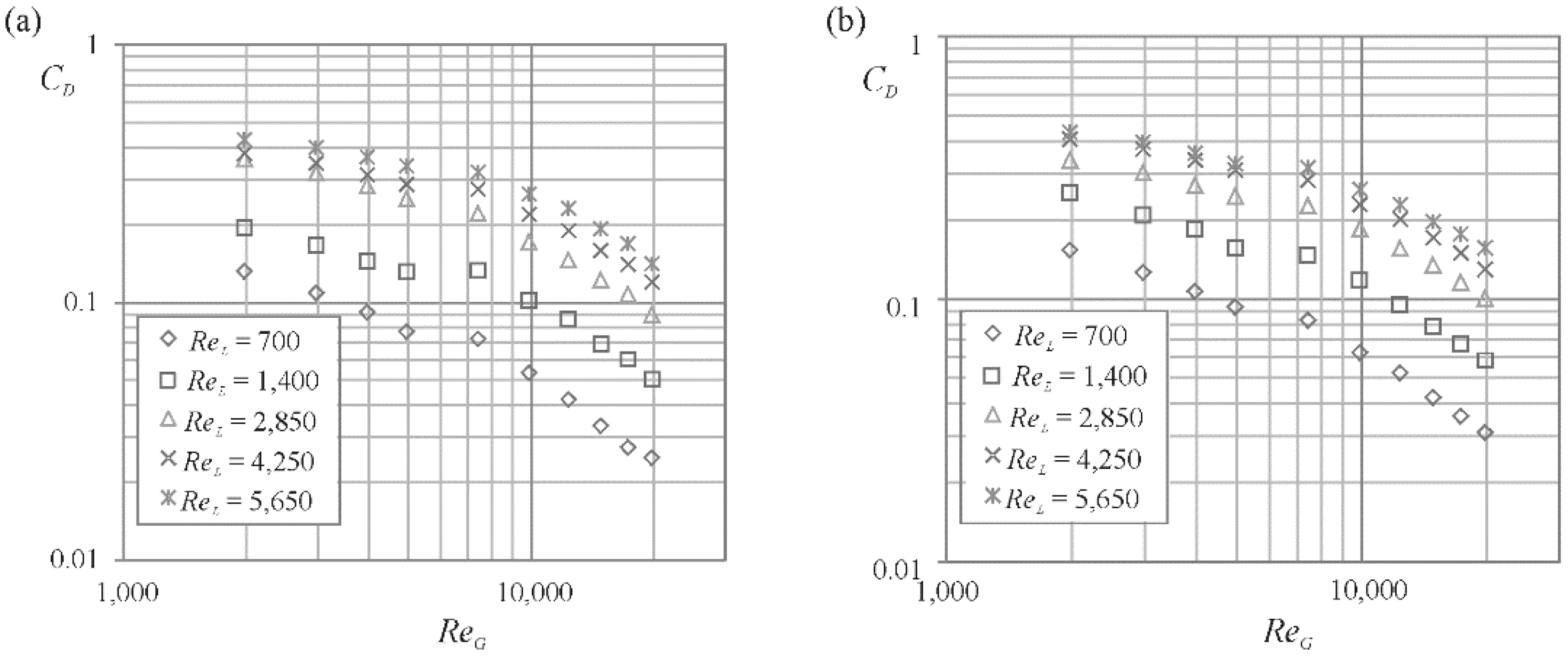
3.2. Discharge Coefficient

Figure 5 presents an exemplary dependence of the discharge coefficient on the Reynolds numbers for gas and liquid. It can be noted that the discharge coefficient value increases with the increase in the ReL value, whereas, with the increase in the ReG value, it decreases. The flow resistances depend on the geometry of the atomizer, which was confirmed, among others, by Broniarz-Press et al. [45] as well as Haddadi and Rahimpour [46]. Data analysis also showed that the value of the discharge coefficient increases with increasing chamber height HS.
Determination of the discharge coefficient value is possible due to the correlation modified for the tested atomizers proposed in the paper [23], which in this case takes the form
C D = 0.0822 · C D ,   t u r G L R 0.53
In this equation, CD,tur is the value of the liquid discharge coefficient during single-phase turbulent flow and takes into account the shape and orifice dimension. The equation is valid for GLR from 0.003 to 0.504. The divergences between the experimental values and the values obtained from the Equation (9) do not exceed ±15%.
Figure 6 presents the discharge coefficient values as a function of gas Reynolds number. The data on the chart were obtained experimentally, determined from the proposed correlation, and calculated on the basis of models describing two-phase flow. The values derived from the proposed equation show smaller deviations from the observed values than the compared models from the paper [19,21]. The equation developed by Chen and Lefebvre [19] does not take into account the influence of the atomizer geometry on the obtained flow coefficient values.

3.3. Spray Angle

The spray angle was estimated from trigonometric relationships. Knowing the motion speed of the grip which the atomizer and the time after which the last point was registered, it is possible to determine one of the triangle sides. The other one is the distance between the atomizer orifice and a measuring point (ha). These side lengths’ ratio is equal to the tangent of half the spray angle.
Based on the conducted experiments, it was observed that the value of the spray angle depends on the operating parameters (gas and liquid flow rates) and geometric dimensions of the atomizer. Figure 7 shows the dependence of the spray angle under the same operating conditions (ReL = 4230, ReG = 6605) as a function of the used atomizer geometry. It has been shown that, along with the increase in HS/DS ratio, the value of the spray angle decreased. A particularly significant change was observed when the ratio of the geometric invariant considered was within the range < 3 ; 4 > . Rashad et al. [42], during the measurements of spray cones’ angle, identified the optimal value 3.75 of the ratio HS/DS. They observed that the increase in HS/DS from 1.25 to 3.75 did not significantly alter the spray cone angle. However, a further increase in this ratio from 3.75 to 5.0 considerably influenced the spray cone angles.
Figure 8 shows the dependence of the spray angle values as a Reynolds number function for liquid and gas obtained for the SA1 atomizer. As the variables increased, an increase in the spray angle was observed.
Using dimension analysis, a dimensionless criterion relation describing the spray angle was determined for the tested type of atomizers in the form
t g θ 2 = A · ( H S D S ) B · R e L C · R e G D · ( H S d 0 ) E ± 12 %
Detailed exponent values were determined using the Statistica program and are presented in Table 2. The critical value was the ratio HS/DS = 3 and, on this basis, two groups of atomizers were determined. The proposed correlation is valid for H S D S ( 0.5 ; 4 ) , R e L ( 1400 ; 5650 ) , R e G ( 2800 ; 9500 ) and H S d 0 ( 8 ; 32 ) . The value of R equals 0.859 for atomizers with HS/DS < 0.5 ;   2 > and 0.970 for atomizers with HS/DS < 3 ;   4 > .

3.4. Volume Distributions of the Size of Spraydroplets

In Figure 9 and Figure 10, the volume frequency (frequency; UV; bars) and cumulative volume (V; line) of droplets are presented. Figure 9 presents the exemplary distributions of spray droplet size obtained for the SA3 atomizer with variable ReL value and constant ReG. Based on the results obtained, it can be observed that, for a higher Reynolds number of liquid, more droplets with large diameters are formed, with a smaller share of medium-size droplets. Several different drop formation mechanisms have been proposed in the literature [47]. In our study, two mechanisms of breakup occur simultaneously—one that results in large drops and another that results in small drops. The bimodal drop size distributions can be observed. The atomizer geometrical dimensions, which influence the volume distribution of droplet diameters, were shown in Figure 10. For the same ReL and ReG values, as well as for the higher HS/DS ratio, fewer droplets with larger diameters were obtained.

3.5. Radial Distributions of the Size of Spray Droplets

Figure 11 and Figure 12 show the exemplary radial distributions of droplet size. It can be seen that the atomizer’s geometry affects the nature of radial distribution, which is particularly evident in the central spray area. The profile of D32 showed a typical hollow cone spray, as the peaks of the drop size met at the spray periphery, which were accelerated even more by the swirl momentum [48]. The results obtained are consistent with the observations. With the increase in ReG, droplets with smaller diameters are formed, and a more uniform distribution of droplet diameters in the stream central area is obtained. The experimental results are in agreement with the results of previous studies of Arcoumanis et al. [38], performed for four inlet pressure-swirl atomizers with a needle.

3.6. Sauter Mean Diameter

Figure 13 shows the exemplary dependence of the obtained mean droplet diameters on the geometric dimensions of the atomizer, expressed as the HS/DS ratio, with the same operating parameters (ReL = 2820, ReG = 6605). Based on the results, it can be noted that the value of the HS/DS ratio significantly affects the value of D32 only after exceeding a specific value. The obtained experimental correlations are referred to in the literature data: according to them, droplet diameter significantly increases after exceeding HS/DS = 2.75 value [49]. Rashad et al. [42] showed that the optimal value is 3.75. In the case of the considered atomizers, the smallest value of D32 was obtained for the construction with HS/DS = 3. This can be explained by the increase in energy loss, with a further increase in the height of the swirl chamber described in Section 3.1.
Figure 14 shows the dependence of the Sauter mean diameter as a function of the gas Reynolds number at the constant liquid Reynolds number. Increasing ReG causes the formation of droplets with smaller diameter. It can also be observed that, with the increase in ReG, the value of D32 decreases.
Based on the obtained data, the following relationship was derived that allows estimating the Sauter mean diameter value for the analyzed atomizers
S M D = D 32 = A · ( H S D S ) B · R e L C · R e G D · ( D S d 0 ) E ± 15 %
The proposed correlation is valid for H S D S ( 0.5 ; 4 ) , R e L ( 1400 ; 5650 ) , R e G ( 2800 ; 9500 ) and D S d 0 ( 8 ; 16 ) . The critical value was the ratio HS/DS = 3 and, on this basis, two groups of atomizers were determined. Detailed exponent values were determined using the Statistica program and are presented in Table 3. The value of R equals 0.966 for atomizers with HS/DS < 0.5 ;   2 > and 0.950 for atomizers with HS/DS < 3 ;   4 > .
Figure 15 shows the convergence of the measured Sauter mean diameters’ values and the values of this parameter, calculated in accordance with the proposed formula.

4. Summary and Conclusions

In this work, the influence of the atomizer geometrical dimensions and its operating parameters on the discharge coefficient, spray angle, volume and radial distribution of droplets in the spray stream, as well as average drop diameter, were analyzed.
The value of the discharge coefficient increases with the increase in ReL value, whereas, with the increase in ReG value, it decreases. In addition, the value of CD depends on the atomizer geometry. As the height of the swirl chamber increases while maintaining its constant diameter, a decrease in the value of the transition cone angle is observed. This results in a smaller stream contraction, which translates into a decrease in the angular momentum and an increase in the CD value.
The spray angle depends on the atomizer’s operating parameters as well as its geometry. As HS/DS ratio increases, the spray angle decreases. As the height of the swirl chamber increases, the additional friction resistance increases, which causes a decrease in the momentum (the quantity of motion). Increasing the Reynolds number of gas and liquid results in a higher spray angle.
It has been shown that the increase in ReG causes the central stream area filling with droplets of smaller diameters and decreasing the mean droplet diameter. On the basis of the obtained volume distributions, it has been shown that, with the increase in liquid Reynolds number, a larger number of droplets with larger diameters is formed. The increase in HS/DS ratio resulted in a smaller number of droplets with larger diameters. Analysis of forming droplets diameters showed that the Sauter mean diameter depends on the HS/DS value. It should be noted that the rapid increase in D32 is above an HS/DS value of around 3.0. This value can be taken as a specific guideline for the design of swirl atomizers for their application.
Atomizers with the proposed design can be an interesting alternative to the commonly used agricultural pressure-swirl atomizers. They allow for the production of optimum droplet size, depending on current weather conditions, without having to replace the atomizer. This allows for a significant drift effect reduction by eliminating the finest droplets of the spray. Obtaining the spray with a narrow spectrum of droplet sizes can maintain the appropriate effectiveness of the treatment, ensuring good droplet penetration, which is particularly important at the early stage of weed control. The presented atomizers allow for better control of the droplets’ diameter and their trajectories compared to conventional solutions, thanks to the possibility of changing the supplied air pressure. This allows for significant savings in the preparation without compromising performance. In addition, it is also possible to spray plants with small doses of atomizing liquid, which reduces water consumption.
The obtained results can increase the knowledge of the phenomenon of two-phase atomization and the principles of pressure-swirl atomizers’ operation, which may contribute to a more precise selection of atomizers and a broadening of their application spectrum.

Author Contributions

Conceptualization, M.O.; S.W. and A.K.; methodology, M.O.; S.W. and T.S.; software, T.S.; A.K. and M.M. (Magdalena Matuszak); validation, A.K.; M.M. (Magdalena Matuszak); M.J. and M.M. (Małgorzata Markowska); formal analysis, M.O. and S.W.; investigation, M.O.; A.K.; S.W.; M.M. (Małgorzata Markowska) and T.S.; writing—original draft preparation, M.O.; A.K.; S.W. and M.J.; writing—review and editing, M.O.; A.K.; S.W. and M.J.; visualization, A.K.; M.M. (Magdalena Matuszak) and M.M. (Małgorzata Markowska); supervision, M.O.; project administration, M.O.; funding acquisition, M.O., S.W. and A.K. All authors have read and agreed to the published version of the manuscript.

Funding

This research was funded by Ministerstwo Nauki i Szkolnictwa Wyższego, grant number PUT 0912/SBAD/0902.

Acknowledgments

The study was supported by the Ministry of Science and Higher Education of Poland through grant No. PUT 0912/SBAD/0902.

Conflicts of Interest

The authors declare no conflict of interest.

References

  1. Lefebvre, A.H.; Ballal, D.R. Gas Turbine Combustion. Alternative Fuels and Emissions; CRC Press: New York, NY, USA, 2010. [Google Scholar]
  2. Orzechowski, Z.; Prywer, J. Spraying Liquid; WNT: Warsaw, Poland, 1991. (In Polish) [Google Scholar]
  3. Koch, R.; Noworyta, A. Mechanical Processes in Chemical Engineering; WNT: Warsaw, Poland, 1998. (In Polish) [Google Scholar]
  4. Bayvel, L.; Orzechowski, Z. Liquid Atomization; Taylor & Francis Inc.: London, UK, 1993. [Google Scholar]
  5. Jedelsky, J. Some Aspects of Effervescent Atomization: Experimental Study Short Version of Habilitation Thesis. D.Sc. Thesis, Brno University of Technology, Brno, Czech Republic, 2013. [Google Scholar]
  6. Liu, H. Science and Engineering of Droplets—Fundamentals and Applications; William Andrew Publishing: New York, NY, USA, 2000. [Google Scholar]
  7. Orzechowski, Z.; Prywer, J. Production and Use of; WNT: Warsaw, Poland, 2008. (In Polish) [Google Scholar]
  8. Ochowiak, M.; Krupińska, A.; Włodarczak, S.; Matuszak, M.; Szulc, T. Analysis of spatial distribution of the size of droplets generated by two-phase atomizers with swirl flow. Chem. Eng. Equip. 2018, 57, 34–35. [Google Scholar]
  9. Grausz, T.W. Chemistry for Farmers BHP. National Labor Inspectorate; Main Labor Inspectorate: Warsaw, Poland, 2015. (In Polish) [Google Scholar]
  10. Li, J.; Huang, Q.; Liu, B. A pest control model with birth pulse and residual and delay effects of pesticides. Adv. Differ. Equ. 2019, 117, 1–16. [Google Scholar] [CrossRef] [Green Version]
  11. Zhang, L.; Song, S.R.; Sun, D.Z.; Xue, X.Y.; Dai, Q.F.; Li, Z. Effects of Liquid Viscosity on Agricultural Nozzle Droplet Parameters. Agric. Sci. 2019, 10, 1217–1239. [Google Scholar] [CrossRef] [Green Version]
  12. Harrison, G.M.; Mun, R.; Cooper, G.; Boger, D.V. A note on the effect of polymer rigidity and concentration on spray atomisation. J. Non-Newton. Fluid Mech. 1999, 85, 93–104. [Google Scholar] [CrossRef]
  13. Mun, R. The effects of polymer concetration and molecular weight on the brakup of laminar capillary jets. J. Non-Newton. Fluid Mech. 1998, 74, 285–297. [Google Scholar] [CrossRef]
  14. Szewczyk, A.; Łuczycka, D.; Owsiak, Z.; Cieniawska, B. Effect of droplet size on coverage of sprayed objects. Prog. Plant Prot. 2013, 53, 822–828. [Google Scholar]
  15. Ramamurthi, K.; Sarkar, U.K.; Raghunandan, B.N. Performance characteristics of effervescent atomizer in different flow regimes. At. Sprays 2009, 19, 41–56. [Google Scholar] [CrossRef]
  16. Wimmer, E.; Brenn, G. Viscous flow through the swirl chamber of a pressure-swirl atomizer. Int. J. Multiph. Flow 2013, 53, 100–113. [Google Scholar] [CrossRef]
  17. Alexiou, A.; Hills, N.J.; Long, C.A.; Turner, A.B.; Wong, L.S.; Millward, J.A. Discharge coefficients for flow through holes normal to a rotating shaft. Int. J. Heat Fluid Flow 2000, 21, 701–709. [Google Scholar] [CrossRef]
  18. Ishibashi, M.; Takamoto, M. Theoretical discharge coefficient of a critical circular-arc nozzle with laminar boundary layer and its verification by measurements using super-accurate nozzles. Flow Meas. Instrum. 2000, 11, 305–313. [Google Scholar] [CrossRef]
  19. Chen, S.K.; Lefebvre, A.H. Discharge coefficients for plain-orifice effervescent atomizers. At. Sprays 1994, 4, 275–290. [Google Scholar]
  20. Lefebvre, A.H. Atomization and Sprays; Hemisphere Publishing Corporation: New York, NY, USA, 1989. [Google Scholar]
  21. Jedelsky, J.; Jicha, M. Prediction of discharge coefficient of internally-mixed twin-fluid atomizers. In Proceedings of the 24th European Conference on Liquid Atomization and Spray Systems ILASS-Europe, Lisbon/Estoril, Portugal, 5–7 September 2011. [Google Scholar]
  22. Lee, E.J.; Oh, S.Y.; Kim, H.Y.; James, S.C.; Yoon, S.S. Measuring air core characteristics of a pressure-swirl atomizer via a transparent acrylic nozzle at various Reynolds numbers. Exp. Therm. Fluid Sci. 2010, 34, 1475–1483. [Google Scholar] [CrossRef]
  23. Ochowiak, M. The Analysis of Liquid Atomization in Effervescent and Effervescent-Swirl Atomizers. Habilitation Thesis, Rozprawy Nr 519, Wydawnictwo Politechniki Poznańskiej, Poznań, Poland, 2014. (In Polish). [Google Scholar]
  24. Ochowiak, M.; Broniarz-Press, L.; Różański, J. The discharge coefficient of effervescent atomizers. Exp. Therm. Fluid Sci. 2010, 34, 1316–1323. [Google Scholar] [CrossRef]
  25. Chinn, J.J. The Numeric of the Swirl Atomizer. In Proceedings of the 22th European Conference on Liquid Atomization and Spray Systems ILASS-Europe, Como Lake, Italy, 8–10 September 2008. [Google Scholar]
  26. Broniarz-Press, L.; Ochowiak, M.; Włodarczak, S.; Matuszak, M.; Maciejewska, A. Analysis of spray angle in pressure-swirl atomizers. Chem. Eng. Equip. 2014, 53, 227–228. [Google Scholar]
  27. Ochowiak, M.; Broniarz-Press, L.; Różańska, S.; Matuszak, M.; Włodarczak, S. Characteristics of spray angle for effervescent-swirl atomizers. Chem. Eng. Process. Process Intensif. 2015, 98, 52–59. [Google Scholar] [CrossRef]
  28. Gavaises, M.; Abo-Serie, E.; Arcoumanis, C. Nozzle hole film formation and its link to spray characteristics in swirl-pressure atomizers for direct injection gasoline engines. Trans. J. Engines 2002, 111, 1942–1954. [Google Scholar]
  29. Arcoumanis, C.; Gavaises, M. Pressure-swirl atomizers for DISI engines: Further modelling and experiments. Trans. J. Engines 2000, 109, 1225–1241. [Google Scholar]
  30. Schick, R.J. Spray Technology Reference Guide: Understanding Drop Size; Spraying Systems Co.: Wheaton, IL, USA, 2008. [Google Scholar]
  31. Pacek, A.W.; Man, C.C.; Nienow, A.W. On the Sauter mean diameter and size distributions in turbulent liquid/liquid dispersions in a stirred vessel. Chem. Eng. Sci. 1998, 53, 2005–2011. [Google Scholar] [CrossRef]
  32. Dafsari, R.A.; Lee, H.J.; Han, J.; Park, D.C.; Lee, J. Viscosity effect on the pressure swirl atomization of an alternative aviation fuel. Fuel 2019, 240, 179–191. [Google Scholar] [CrossRef]
  33. Jasuja, A.K. Atomization of crude and residual fuel oils. ASME J. Eng. Power 1979, 101, 250–258. [Google Scholar] [CrossRef]
  34. Wang, X.F.; Lefebvre, A.H. Mean drop sizes from pressure-swirl nozzles. AIAA J. Propuls. Power 1987, 3, 11–18. [Google Scholar] [CrossRef]
  35. Liu, C.; Liu, F.; Yang, J.; Mu, Y.; Hu, C.; Xu, G. Experimental investigations of spray generated by a pressure swirl atomizer. J. Energy Inst. 2019, 92, 210–221. [Google Scholar] [CrossRef]
  36. Dumouchel, C.; Bloor, M.I.G.; Dombrowski, N.; Ingham, D.B.; Ledoux, M. Viscous flow in a swirl atomizer. Chem. Eng. Sci. 1993, 48, 81–87. [Google Scholar] [CrossRef]
  37. Rezaeimoghaddam, M.; Moin, H.; Modarres Razavi, M.R.; Pasandideh-Fard, M.; Elahi, R. Optimization of a high pressure swirl injector by using volume-of-fluid (VOF) method. In Proceedings of the ASME 2010 10th Biennial Conference on Engineering Systems Design and Analysis ESDA2010, Istanbul, Turkey, 12–14 July 2010; ESDA2010-24614. pp. 435–445. [Google Scholar]
  38. Arcoumanis, C.; Gavaises, M.; Argueyrolles, B.; Galzin, F. Modelling of pressure-swirl atomisers for GDI engines. Trans. J. Engines 1999, 108, 516–532. [Google Scholar]
  39. Le Coz, J.F.; Hermant, L. Visualisation of sprays generated by direct injection gasoline injectors. In Proceedings of the 14th Annual Conference on Liquid Atomization and Spray Systems ILASS-Europe, Toulouse, France, 5–7 July 1999. [Google Scholar]
  40. Gavaises, M.; Arcoumanis, C. Modelling of sprays from high-pressure swirl atomisers. Int. J. Engine Res. 2001, 2, 95–117. [Google Scholar] [CrossRef]
  41. Cousin, J.; Ren, W.M.; Nally, S. Transient flows in high pressure swirl injectors. SAE Tech. Pap. 1998, 980499. [Google Scholar]
  42. Rashad, M.; Yong, H.; Zekun, Z. Effect of geometric parameters on spray characteristics of pressure swirl atomizers. Int. J. Hydrog. Energy 2016, 41, 15790–15799. [Google Scholar] [CrossRef]
  43. Liu, W.; Bai, B. Swirl decay in the gas–liquid two-phase swirling flow inside a circular straight pipe. Exp. Therm. Fluid Sci. 2015, 68, 187–195. [Google Scholar] [CrossRef]
  44. Ochowiak, M. The experimental study on the viscosity effect on the discharge coefficient for effervescent atomizers. Exp. Therm. Fluid Sci. 2013, 50, 187–192. [Google Scholar] [CrossRef]
  45. Broniarz-Press, L.; Ochowiak, M.; Włodarczak, S.; Markuszewska, M. Analysis of the liquid outflow coefficient for swirl atomizers with different shapes of the outlet orifice. Chem. Eng. Equip. 2013, 52, 403–404. [Google Scholar]
  46. Haddadi, H.; Rahimpour, M. A discharge coefficient for a trapezoidal broad-crested side weir in subcritical flow. Flow Meas. Instrum. 2012, 26, 63–67. [Google Scholar] [CrossRef]
  47. Dhivyaraja, K.; Gaddes, D.; Freeman, E.; Tadigadapa, S.; Panchagnula, M.V. Dynamical similarity and universality of drop size and velocity spectra in sprays. J. Fluid Mech. 2019, 860, 510–543. [Google Scholar] [CrossRef]
  48. Dafsari, R.A.; Lee, H.J.; Han, J.; Lee, J. Evaluation of the atomization characteristics of aviation fuels with different viscosities using a pressure swirl atomizer. Int. J. Heat Mass Transf. 2019, 145, 118704. [Google Scholar] [CrossRef]
  49. Elkotb, M.M.; Rafat, N.M.; Hanna, M.A. The influence of swirl atomizer geometry on the atomization performance. In Proceedings of the 1st International Conference on Liquid Atomization and Spray Systems, Tokyo, Japan, 27–31 August 1978; pp. 109–115. [Google Scholar]
Figure 1. Scheme of experimental set-up: 1—compressor, 2—gas rotameter, 3—liquid rotameter, 4—gantry crane, 5—atomizer, 6—Spraytec analyzer, 7—liquid tank, 8—pump, 9—computer.
Energies 13 03416 g001
Figure 2. Atomizers used in the experiments.
Energies 13 03416 g002
Figure 3. The characteristic values of GLR ratio vs. dimensionless Reynolds numbers.
Energies 13 03416 g003
Figure 4. The dependence of swirl number on GLR ratio for SA1 atomizer.
Energies 13 03416 g004
Figure 5. Exemplary dependence of the discharge coefficient value as a function of the Re number of gas and liquid: (a) SA2 atomizer (HS/DS = 2); (b) SA5 atomizer (HS/DS = 4).
Energies 13 03416 g005
Figure 6. Comparison of obtained discharge coefficients with model ones for SA1: (a) ReL = 700; (b) ReL = 1410.
Energies 13 03416 g006
Figure 7. The dependence of the spray angle on the construction geometry.
Energies 13 03416 g007
Figure 8. The dependence of the spray angle on the Reynolds number of gas and liquid.
Energies 13 03416 g008
Figure 9. Exemplary volume distributions of the size of spray droplets for SA3 atomizer and the Reynolds number of gas ReG = 9435: (a) ReL = 2820, (b) ReL = 5640.
Energies 13 03416 g009
Figure 10. Exemplary volume distributions of the size of spray droplets obtained for two different atomizers: (a) SA3 (HS/DS = 3), (b) SA7 (HS/DS = 1).
Energies 13 03416 g010
Figure 11. Exemplary radial distribution of the mean diameters of droplets in liquid stream ReL = 2820 and ReG = 6605 (r—distance from the spray axis).
Energies 13 03416 g011
Figure 12. Radial distribution of the mean diameters of spray droplets obtained for SA1 atomizer and the Reynolds number of liquid ReL = 4230.
Energies 13 03416 g012
Figure 13. Dependence of the mean Sauter diameter on the geometric dimensions of atomizer.
Energies 13 03416 g013
Figure 14. Dependence of the mean Sauter diameter on the Reynolds number of gas, with the liquid Reynolds number ReL = 2820.
Energies 13 03416 g014
Figure 15. The measured values of the Sauter mean diameters and the values calculated from Equation (11).
Energies 13 03416 g015
Table 1. The dimensions of the atomizers.
AtomizerDiameter of Chamber
DS [mm]
Height of Chamber
HS [mm]
SA-120 ± 0.120 ± 0.1
SA-220 ± 0.140 ± 0.1
SA-320 ± 0.160 ± 0.1
SA-420 ± 0.170 ± 0.1
SA-520 ± 0.180 ± 0.1
SA-640 ± 0.120 ± 0.1
SA-740 ± 0.140 ± 0.1
SA-840 ± 0.160 ± 0.1
SA-940 ± 0.180 ± 0.1
Table 2. The values of fitting parameters from the Equation (10).
ATOMIZERS   H S D S < 0.5 ; 2 >  
value
A0.050
B−0.007
C0.062
D0.110
E0.106
ATOMIZERS   H S D S < 3 ; 4 >
value
A0.186
B−1.735
C0.020
D0.040
E0.529
Table 3. The values of fitting parameters from the Equation (11).
ATOMIZERS   H S D S < 0.5 ; 2 >
value
A0.504
B0.083
C0.026
D−0.915
E0.038
ATOMIZERS   H S D S < 3 ; 4 >
value
A0.246
B0.834
C0.017
D−1.011
E0.427

