Article

Potential for CO2 Reduction by Dynamic Wireless Power Transfer for Passenger Vehicles in Japan

Graduate School of Frontier Science, The University of Tokyo, Chiba 2778561, Japan
*
Author to whom correspondence should be addressed.
These authors contributed equally to this work.
Energies 2020, 13(13), 3342; https://doi.org/10.3390/en13133342
Submission received: 2 June 2020 / Revised: 23 June 2020 / Accepted: 27 June 2020 / Published: 30 June 2020
(This article belongs to the Section E: Electric Vehicles)

Abstract

:
In this study, a novel system named the third-generation wireless in-wheel motor (WIWM-3), which has a dynamic wireless power transfer (DWPT) system, is developed. It can extend the cruise range, which is one of the key specifications of electric vehicles. DWPT also reduces CO2 emission as the driving resistance is reduced due to light weight of the batteries. In this study, CO2 emission by an internal combustion vehicle, a long range drivable electric vehicle with the same cruise range, and an electric vehicle with WIWM-3 equipped with the DWPT system are analyzed using actual measurement data and calculated data based on actual measurement or specification data. A WPT system with WIWM-3 achieves 92.5% DC-to-DC efficiency as indicated by an actual measurement at the nominal position. Thus, the electric vehicle with DWPT can reduce up to 62% of CO2 emission in internal combustion vehicles, and the long-range drivable vehicle emits 17% more CO2 than the electric vehicle with DWPT. Moreover, it is expected that by 2050, electric vehicles with DWPT will reduce CO2 emissions from internal combustion vehicles by 95% in Japan. DWPT systems make electric vehicles more sustainable and, hence, more acceptable for consumers.

1. Background

Reduction of CO 2 emission is one of the most pressing issues in the world today, and Japan was ranked fifth in the world with respect to CO 2 emissions in 2017 [1]. Transportation is responsible for 17.9% of CO 2 emission in Japan, and includes passenger vehicles, trucks, buses, bikes, trains, airplanes and ships [2]. In addition, passenger vehicles form the largest fraction of CO 2 emission per mass when compared to trucks, trains, airplanes, and ships [3]. Therefore, CO 2 emission reduction for passenger vehicles is an effective strategy to attain such environmental goals.
The conventional approach for extending the cruise range of electric vehicle, that is, increasing the number of batteries on the vehicles, is not suitable for realizing a sustainable vehicle. Electric vehicles have, thus, been developed to mitigate CO 2 emissions. They are not in much demand yet. Since electric vehicles do not have sufficient cruise range, their cost is higher than that of internal combustion vehicles. A simple solution to extend the cruise range involves increasing the number of batteries on the vehicles. However, this makes electric vehicles expensive, heavy, and inefficient. Though electric vehicles do not emit any CO 2 , thermal power plants emit CO 2 during power generation. In 2018 (fiscal year), electricity from thermal power plants forms the largest percentage in Japan, i.e., 81%, of the total electric production. Excluding a few, almost all countries use thermal power plants. Therefore, to improve the efficiency of electric vehicles, it is necessary to realize a sustainable vehicle. Moreover, there is a risk of depletion of manganese in the battery [4].
On the other hand, there is a novel technology named dynamic power transfer to extend the cruise range. Dynamic power transfer can be of two methods. One is dynamic direct charging [5], and the other is a dynamic wireless power transfer. DWPT is safer than direct charging due to the non-dynamic electric connection. The direct dynamic charging terminals are worn out by the friction between moving terminals. This wear causes sparking and may even lead to fires.
However, the conventional electromagnetic induction WPT is not efficient with large coil gaps or misalignment between the transmitting coil and the receiving coil, and it is suitable only for stationary applications. To solve these problems, WPT with magnetic resonance coupling was proposed in 2007 [6]. Therefore, some DWPT projects for passenger vehicles adopt magnetic resonance coupling for DWPT systems [7,8,9,10,11,12]. A DWPT system that may be adopted for both passenger vehicles and trucks [13] has been proposed. Moreover, DWPT is also studied as a potential charging system for some transportation applications, which are a transportation robot [14], a train [15], or a garbage collection truck [16]. Not only the system, but also the control [17] or circuit topologies [18], have been actively researched. A DWPT system with capacitive coupling, [19,20] has been also proposed. Capacitive coupling uses the capacitance between the transmitter and receiver. The strong point of capacitive coupling is its high efficiency and simple structure. However, when it is raining, and water penetrates between the transmitter and receiver, electric field coupling cannot be used easily due to a change in capacitance between the transmitting side and the receiving side. Therefore, the DWPT system with electric field coupling cannot be used on public roads. Stationary charging may, however, lead to another problem. For example, while autonomous vehicles do not require humans to drive, human intervention is still necessary to charge the vehicles. Naturally, the next step would be to eliminate human intervention.
This paper aims to provide a procedure of calculation for CO 2 emission by vehicles, and reveal the benefit of DWPT for reduction of CO 2 quantitatively.

2. CO2 Emission by Electric Vehicle

2.1. CO2 Emission Procedure by Electric Vehicle

Well-to-wheel CO 2 emission is an important evaluation function for electric vehicles. It includes CO 2 emission by the generation loss, loss of grid, loss of charging and driving. Thus, the well-to-wheel CO 2 emission E C O 2 ele by electric vehicles is as described below.
E C O 2 ele = E F ele E C v .
Here, E F ele is the emission factor, and E C v is the energy consumption of the electric vehicle. Then, there are two ways to reduce CO 2 by vehicles. One is the reduction of CO 2 at the generation stage itself by using renewable energy or building more efficient power plants, and the other is improving the driving efficiency.

2.2. Analysis for Energy Consumption of Electric Vehicle

First, the energy consumption of an electric vehicle is analyzed based on the specifications as well as the actual measurement data. The analyzed vehicle is a commercialized sedan-type electric vehicle. The specification of the target vehicle is displayed in Table 1.
The energy required for driving can be calculated using vehicle mass, vehicle speed, driving resistance, and driving efficiency. Vehicle mass, electricity consumption, and cruise range are mentioned in the specification sheet of the target vehicle [21]. The road resistance and air resistance coefficients are measured values obtained in a coasting-down test. This analysis is based on the Worldwide Harmonized Light Vehicles Test Procedure (WLTP), which is an international test regulation for new vehicles. The vehicle speed is given, and the slope of the road is not considered. The driving resistance of the vehicle is described in the expression below:
F resist = μ r ( m v + m p + m b ) + μ Aa v 2 .
Here, F resist is the driving resistance and v is the vehicle speed. The driving force is obtained as shown below:
F drive = F resist + m v α v ,
where α v is the acceleration or deceleration of the vehicle. Then, the battery output or input by driving is described by the following equation:
P drive = F drive D drive η drive ( F drive > 0 ) F drive D drive η drive ( otherwise )
Here, η drive is the driving efficiency, which includes the efficiency of the driving components and charging efficiency from grid to battery, and D drive is the driving distance with F drive . The energy while driving is described below:
E drive = η chg 0 t P drive ( t ) dt .
Here, η chg is the charging efficiency and t is the driving mode duration. η chg is calculated using the cruise range and energy consumption as shown in below. This charging efficiency includes not only the efficiency of the charger but also loss of charging circuit in the vehicle and the battery loss.
η chg = R c C bat E C spec
E C spec includes the driving efficiency and charging efficiency. Thus, the calculated energy consumption with the cruise range and battery capacity is different from the energy consumption described in the specification sheet. In this analysis, average driving efficiency η dave is used, because the detail of driving efficiency is not published. η dave is given by the following equation:
η dave = 3.6 E spec D mode 0 t F drive ( t ) v ( t ) dt .
Here D mode is driving distance of mode driving and 3.6 is a coefficient for unit conversion. Thus, analyzed driving power P mdrive is calculated by this equation:
P mdrive = F drive D drive η dave ( F drive > 0 ) F drive D drive η dave ( otherwise )
Then, the driving energy of the mode drive E mdrive is described as below:
E mdrive = η chg η dave 0 t F drive ( t ) v ( x ) dt
Finally, the calculated electric coefficient of mode drive E C ana is described as this equation:
E C ana = E mdrive D mode .
As the result, the charging efficiency of the target electric vehicle is 84%, and the average driving efficiency is 88.6% calculated using the parameters in Table 1. The result of the loss analysis shown in Figure 1. E C ana is set to be the same as E C spec in this analysis.
The air resistance accounts for 52.1% of the total loss. The rolling resistance is 37.9%, and the driving efficiency loss is 18.8% of the total loss. Vehicle mass is only one parameter that affects both the rolling resistance and driving efficiency, and the total is approximately half of the driving loss. Especially, without the extra high-speed mode, which is one of the categories of Worldwide harmonized Light duty Test Cycle (WLTC) which is regulated in WLTP, the rolling resistance loss and driving efficiency loss are 62.1% of the total loss. Though the vehicle speed extra high mode is more than 120 km/h, there is only 80 km of highway where the speed limit is 120 km/h in Japan. Thus, weight reduction is the most effective way to decrease energy requirements.

3. CO2 Reduction by DWPT System

3.1. Wireless In-Wheel Motor

We have developed a novel driving system named the wireless in-wheel motor (WIWM). It integrates the driving system and dynamic charging system, which include motor, inverter, rectifier, control unit, cooling system, and receiving coil in the unsprung area. The latest one, named the third generation of wireless in-wheel motor (WIWM-3), is shown in Figure 2.
The uniqueness of WIWM is the position of the receiver coil. There is a regulation for minimum under clearance of body side parts to avoid obstacles. However, the parts set into the unsprung area are not regulated, because they move with the tire due to its unsprung setting, and it can avoid road obstacles with the tire itself. Therefore, the air gap with the transmitter coil is kept constant even when the suspension is displaced and the air gap can be minimized. Moreover, the receivable energy can be chosen by a number of the receiver coils and it can adjust a lot of variations of vehicles.
WIWM adopts magnetic resonance coupling, and thus, minimizing the air gap is effective in improving the WPT efficiency. Moreover, the air gap affects parametric optimization to maximize the efficiency of the system, and the constant air gap is suitable for efficient control. This DWPT system has a series–series (SS) type WPT system. SS type can realize high efficiency with robust control [22]. The equivalent circuit of SS type WPT system is displayed in Figure 3. The equivalent load R L η max when WPT system transmits with maximum efficiency is described as below:
R L η max = R 2 ( ω 0 L m ) 2 R 1 + R 2 .
Here, R is resistance, L is inductance, and ω 0 is the frequency of transmitter current. The index number 1 is the transmitter side, and 2 is the receiver side. L m is mutual inductance between the transmitter coil and the receiver coil. Then, the equivalent load R L with voltage load like battery is described as below:
R L = R 1 R 2 + ( ω 0 L m ) 2 R 1 + R 2 V 2 ω 0 L m V 1 R 2 V 2 .
Here, V is voltage, and I is current. When the voltage of the transmitter side V 1 and circuit parameters are given, the equivalent load is given by the voltage of the receiver side alone. System configuration of WIWM-3 is shown in Figure 4. There is an up-converter between the battery and WIWM-3, and the equivalent load can be controlled to R L η max .
WIWM-3 has six states of DWPT. Received energy from the transmitting coil can be used for driving directly or charging the battery or for both these operations. They are decided by the battery state and balance of driving output P drive and output energy from WPT P wpt .
(a)
Driving with Energy of Battery and WPT
When P drive is bigger than P wpt , driving output is supplied by both battery and WPT receiving energy.
(b)
Driving with only Energy of WPT
When P drive and P wpt are same, driving output is supplied by only WPT receiving energy. WIWM-3 has an active rectifier, thus P wpt can be controlled by pulse width control of power device. Even though P wpt is much bigger than the received energy, it can be controlled just as P drive . Therefore, when the battery cannot be charged, for example, when the battery state of charge (SOC) is high enough, driving output is also supplied by the WPT receiving energy alone.
(c)
Driving with only battery power
When there is no transmitter coil, WIWM-3 drives only with battery power.
(d)
Driving and Charging using WPT energy
When P drive is smaller than P wpt and the battery is chargeable, the received energy from WPT may be applied to both driving and battery charging.
(e)
Charging with Energy of Regeneration and WPT
When the motor is regenerating, and the battery is chargeable, both regenerating energy and WPT energy are used for charging the battery.
(f)
Charging with Energy of WPT
When P drive is zero, the vehicle is stopping or coasting down, WPT energy supplies to only the battery.
(g)
Not Driving or Charging
When the battery is not rechargeable, power devices of the active rectifier short circuit with the receiver coil and stop charging.
All the states are displayed in Figure 5.

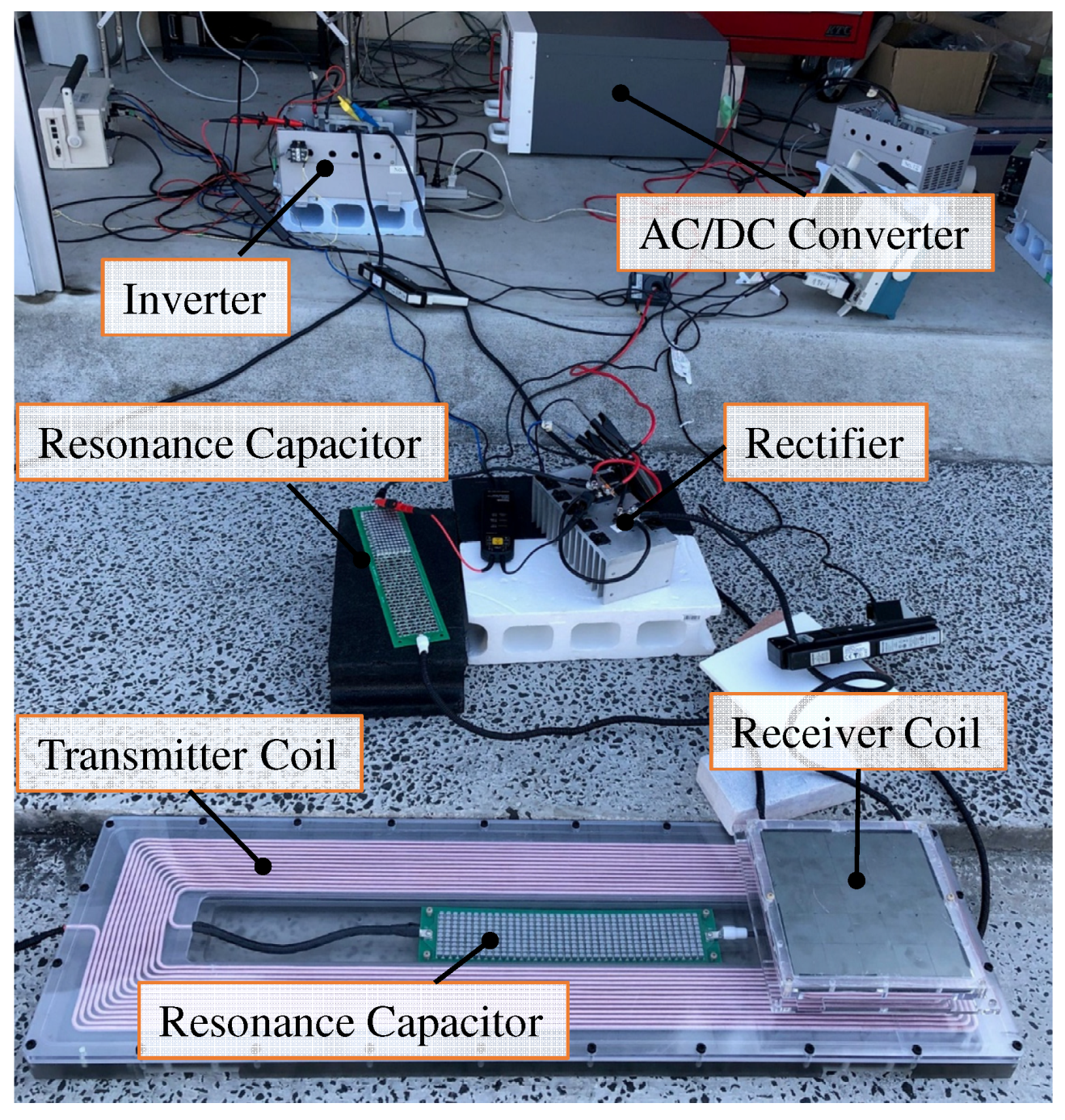
3.2. Efficiency of WPT

In this study, the parameters of the WPT system are based on WIWM-3. The specification of the WTP system is shown in Table 2. V bat is the voltage of battery output. These parameters are the measured values set at a nominal position of 85 kHz, which is in the regulated frequency range of SAE J2954. SAE J2954 is a standard of stationary WPT system for electric vehicles. Coil size consists of the wire, coil case, and ferrite blocks. The transmitter coil and receiver coil are displayed in Figure 6. The maximum voltage of the resonant capacitor of the transmitter side will be 7 kV, then the board of resonance capacitors is set into the center of the coil to decrease line voltage outside of the transmitter coil case. Charging energy of DWPT is decided by the WPT power, vehicle speed, and the receivable area. Then the transmitter coil is bigger than the receiver coil due to the increase in the received energy. The effective voltage of WPT V 2 in the form of a rectangular wave, and the minimum V 2 is the fundamental wave of the battery DC voltage V bat . Transmit efficiency is evaluated in the WPT bench displayed in Figure 7. The output of AC/DC converter which is supplied AC voltage from the distribution board is connected to both transmitter side and receiver side. Then, V 1 and V 2 are the same during evaluation and are not optimized to maximum efficiency. The inverter of the transmitter consists of an SiC power device due to high-frequency switching. The specification of SiC power device of the transmitter is in Table 3 [23]. The rectifier can be used for synchronous rectification. The test result at 85 kHz is shown in Figure 8. DC Voltage supply is 499.3 V, and thus, V 1 and V 2 are in the range of the specification. DC-to-DC efficiency which includes the inverter loss, copper loss, iron loss, and rectifier loss reached 92.5% with 20 kW output.
Reduction of theoretical maximum efficiency caused by lateral misalignment, which is calculated with equation described below, is also evaluated.
k = L m L 1 L 2
Q i = ω 0 L i R i ( i = 1 or 2 )
η max = k 2 Q 1 Q 2 ( 1 + 1 + k 2 Q 1 Q 2 )
Here, k is the coupling factor, and Q is the quality factor of the coils. The result of theoretical maximum efficiency change by misalignment is displayed in Figure 9. With 60 mm lateral misalignment, there is 0.6% reduction of theoretical efficiency.

4. CO2 Reduction by DWPT System

4.1. Precondition of Comparison

Electric vehicles can reduce battery storage to 5 kWh with DWPT for urban use in Japan [24]. However, in the feasibility study, this research sets the battery storage of electric vehicles with DWPT 15 kWh. From the specifications of the two types of vehicles that have the same body frame, but different battery storage [21]. The energy density of the battery can be calculated as 137.6 Wh/kg by the difference of mass of the two types of vehicle and difference of battery capacity of the two vehicles. Then change of vehicle mass m b by changing battery capacity is calculated as below:
m b = c b d b .
Here, c b is change of battery capacity, and d b is energy density of battery. Therefore, the mass reduction of the battery for the target vehicle is 341 kg. The mass of the receiver coil must be added to the vehicle. In this study, there are two coils of mass 5 kg each on the vehicle. We assume that the mass of the additional circuit is the same as the mass of the conventional onboard charger which is removed from the DWPT vehicles. Thus, the total mass reduction for the target vehicle is 331 kg.
Next, the comparative electric vehicle specification is considered. The target electric vehicle does not have sufficient cruise range, and therefore, we estimate the vehicle mass of the target vehicle which has the same cruise range as the internal combustion vehicle. The specifications of the internal combustion vehicle for comparison in the passenger vehicle C segment are listed in Table 4. Then, the target cruise range of the electric vehicle is set to 730 km. The specifications of the electric vehicle with the DWPT system compared with the long-range drivable electric vehicle are shown in Table 4. Parameters in the Table 5 are calculated with the same driving efficiency and charging efficiency of the target vehicle. The long-range drivable electric vehicle is much heavier than the DWPT electric vehicle due to a large number of batteries. The efficiency of the DWPT system set at 92.5% is the same as WIWM-3. Therefore, emission factors are listed in Table 6 [25,26,27].

4.2. Comparison of CO2 Emission

Emission of a DWPT electric vehicle is compared with the internal combustion vehicle and the long-range drivable electric vehicle. Evaluation is based on the WLTC mode. CO 2 emission of the internal combustion vehicle E C O 2 gas is described using this equation.
E C O 2 gas = F C gas ( E F tank C V gas + E F gas )
F C gas E F tank C V gas is well-to-tank emission, and F C gas E F gas is tank-to-wheel emission. CO 2 emission of the long-range drivable electric vehicle is calculated by Equations (1) and (10). CO 2 emission of the DWPT electric vehicle is also calculated by Equations (1) and (10); however, the driving energy of mode drive E mdrive is changed due to WPT efficiency. Considering the WPT efficiency, E mdrive is described as shown below in this study.
E mdrive = η dchg η chg η dave 0 t F drive ( x ) v ( x ) dx
Then, the simulation result of CO 2 emission with the values in Table 4, Table 5 and Table 6 is shown in Figure 10. The long-range drivable electric vehicle can reduce CO 2 emission of the internal combustion vehicle by 57.4%. Moreover, the lightweight electric vehicle with the DWPT system can reduce CO 2 emission of the internal combustion vehicle by 63.1%. Thus, the long-range drivable electric vehicle will emit 16% more than the electric vehicle with DWPT. In 2050, the Japanese target for CO 2 emission reduction during generation is to 12% of the values in 2019 [28]. Therefore, DWPT has the potential to decrease CO 2 emission in an internal combustion vehicle by 95% in 2050.
The loss of the long-range drivable electric vehicle and the electric vehicle with DWPT is also analyzed. The result of the loss analysis is displayed in Figure 11. The air resistance loss is not changed, because the vehicle mass does not affect the air resistance. The rolling resistance loss of the electric vehicle with DWPT decreases by 38% compared with the long-range drivable electric vehicle. Moreover, the driving efficiency loss of the electric vehicle with DWPT also decreases to 22% of the long-range drivable electric vehicle. The basic loss is 7.5% of charging energy due to 92.5% WPT efficiency.

4.3. Sensitivity Analysis for Parameters

The sensitivity of the parameters is also analyzed. Some parameters adopt estimated values or are based on one study. Hence, there is uncertainty in the assumptions adopted for simulation remain. Therefore analyzed parameters relate the strong point of the DWPT system. A strong point of DWPT is the reduction for the mass of batteries. Then, the analyzed parameters which have relation for the mass of battery are energy density of the battery, the capacity of battery loading the electric vehicle with DWPT. Charging loss of DWPT is also analyzed. Each sensitivity analysis is with ±20% parameter change. The evaluation function is the difference of CO 2 emission between the long-range drivable electric vehicle and the electric vehicle with DWPT.
The result of sensitivity analysis is shown in Figure 12. Even though these three parameters are 20% worse at the same time, the benefit of CO 2 reduction by DWPT remains 5.8 g-CO 2 /km.
The most effective parameter is the energy density of the battery. The benefit of CO 2 emission by the electric vehicles with DWPT decreases 35% by increasing 20% energy density of the battery. The benefit of DWPT decreases, however increasing the energy density of the battery is a welcome advance, because it benefits both the long-range drivable electric vehicle and the electric vehicle with DWPT.
The second is the mass of battery for the electric vehicle with DWPT. The benefit of CO 2 emission by the electric vehicles with DWPT decreases 10% by increasing 20% mass of battery for the electric vehicle with DWPT. Mass of battery for the electric vehicle with DWPT depends on the number of the transmitter coils [24]. The initial and maintenance cost of transmitter coils also depends on the number of the transmitter coils. Hence the balance of the total cost for transmitter coil and benefit of CO 2 reduction will be an economic problem.
The least effective parameter is the loss of DWPT. The benefit of CO 2 emission by the electric vehicles with DWPT decreases 4% by increasing 20% loss of DWPT. DWPT efficiency is reduced by misalignment or production error. Hence, autonomous driving or drive assist system which helps accurate drive will be able to give customers more benefit. In the same way, it is important to improve robustness to changes in the coupling factor due to misalignment through control [29] or circuit configuration [30].

5. Discussion

The plans for future work are the following:
(1)
Improve efficiency
WPT efficiency can be improved by controlling the DC voltage of the receiver side or active rectifier. That includes robustness for frequency change or misalignment.
(2)
Evaluation of durability and reliability
The reliability or durability test of the system has not been conducted, and there may be unexpected problems.
It is necessary not only to decrease the energy of driving but also to decrease the emission factor. Therefore, we will also have to discuss a concrete solution for achieving the target emission factor in 2050.
Since the DWPT system is fairly large-sized, commercializing the DWPT system for electric vehicles may lead to problems related to social implementation, pertaining to regulations, services, or construction of DWPT roads. Compatibility with the conventional WPT system which has the receiver coil on the board will be a problem. Therefore, we will cooperate with ministries and companies, and act multi-directionally. However, this is not enough, since electric vehicles must be designed for the international market. The DWPT system also has to be designed to be acceptable for international consumers and society and studied with such a situation in mind.

6. Conclusions

This study has proposed a novel DWPT system named WIWM-3 and analyzed the CO 2 emission for three representative vehicle types, the internal combustion vehicle, the long-range drivable electric vehicle and the electric vehicle with DWPT. WIWM-3 is evaluated with actual measurement and it achieves high efficiency and output enough to be adopted as a DWPT system for passenger vehicles. By analysis, it is revealed that decreasing the mass of the vehicle is the most effective strategy for the reduction of CO 2 emission. The authors also revealed that long-range drivable electric vehicles are not sustainable now due to their heavy batteries and DWPT has a high potential for reduction of CO 2 by electric vehicles.

Author Contributions

Formal analysis, O.S.; investigation, O.S.; project administration, H.F.; resources, S.N. and T.F.; supervision, H.F.; writing—original draft, O.S.; writing—review and editing, S.N., T.F. and H.F. All authors have read and agreed to the published version of the manuscript.

Funding

This work was funded by JSPS KAKENHI Grant Number 18H03768 and JST-Mirai Program Grant Number JP-MJMI17EM, and the EIG CONCERT-Japan 4th Call under the Strategic international Research cooperative Program of JST, Japan.

Acknowledgments

This work was partly supported by JSPS KAKENHI Grant Number 18H03768 and JST-Mirai Program Grant Number JP-MJMI17EM, and the EIG CONCERT-Japan 4th Call under the Strategic international Research cooperative Program of JST, Japan.

Conflicts of Interest

The authors declare no conflict of interest.

References

  1. International Energy Agency Home Page. Available online: https://www.iea.org/data-and-statistics/data-tables?country=JAPAN&energy=Balances&year=2017 (accessed on 27 April 2019).
  2. Ministry of Land, Infrastructure, Transport and Tourism Japan Home Page. Available online: https://www.mlit.go.jp/sogoseisaku/environment/sosei_environment_tk_000007.html (accessed on 27 April 2019).
  3. National Greenhouse Gas Inventory Report of JAPAN. Available online: http://www-gio.nies.go.jp/aboutghg/nir/2020/NIR-JPN-2020-v3.0_GIOweb.pdf (accessed on 27 April 2019).
  4. Oliveira, L.; Messagie, M.; Rangarajum, S.; Sanfelix, J.; Hernandez, M.; Joeri, R.; Mierlo, V. Key issues of lithium-ion batteries—From resource depletion to environmental performance indicators. J. Clean. Prod. 2015, 108, 354–362. [Google Scholar] [CrossRef]
  5. Tajima, T.; Noguchi, W.; Aruga, T. Study of a Dynamic Charging System for Achievement of Unlimited Cruising Range in EV; SAE Technical Paper 2015-01-1686; SAE International: Warrendale, PA, USA, 2015. [Google Scholar] [CrossRef]
  6. Kurs, A.; Karalis, A.; Moffatt, R.; Joannopoulos, J.D.; Fisher, P.; Soljacic, M. Wireless power transfer via strongly coupled magnetic resonances. Science 2007, 317, 83–86. [Google Scholar] [CrossRef] [PubMed] [Green Version]
  7. Fujita, T.; Yasuda, T.; Akagi, H. A Dynamic Wireless Power Transfer System Applicable to a Stationary System. IEEE Trans. Ind. Appl. 2017, 53, 3748–3757. [Google Scholar] [CrossRef]
  8. Zaheer, A.; Neath, M.; Beh, H.Z.Z.; Covic, G.A. A Dynamic EV Charging System for Slow Moving Traffic Applications. IEEE Trans. Transp. Electrif. 2017, 3, 354–369. [Google Scholar] [CrossRef]
  9. Patil, D.; McDonough, M.K.; Miller, J.M.; Fahimi, B.; Balsara, P.T. Wireless Power Transfer for Vehicular Applications: Overview and Challenges. IEEE Trans. Transp. Electrif. 2018, 4, 3–37. [Google Scholar] [CrossRef]
  10. Jiang, C.; Sun, Y.; Wang, Z.; Tang, C. Multi-Load Mode Analysis for Electric Vehicle Wireless Supply System. Energies 2018, 11, 1925. [Google Scholar] [CrossRef] [Green Version]
  11. Choi, S.Y.; Gu, W.B.; Jeong, S.Y.; Rim, C.T. Advances in Wireless Power Transfer Systems for Roadway-Powered Electric Vehicles. IEEE J. Emerg. Sel. Top. Power Electron. 2015, 3, 18–36. [Google Scholar] [CrossRef]
  12. Mi, C.C.; Buja, G.; Choi, S.Y.; Rim, C.T. Modern Advances in Wireless Power Transfer Systems for Roadway Powered Electric Vehicles. IEEE Trans. Ind. Electron. 2016, 63, 6533–6545. [Google Scholar] [CrossRef]
  13. Tan, L.; Zhao, W.; Ju, M.; Liu, H.; Huang, X. Research on an EV Dynamic Wireless Charging Control Method Adapting to Speed Change. Energies 2019, 12, 2214. [Google Scholar] [CrossRef] [Green Version]
  14. Tampubolon, M.; Pamungkas, L.; Chiu, H.-J.; Liu, Y.-C.; Hsieh, Y.-C. Dynamic Wireless Power Transfer for Logistic Robots. Energies 2018, 11, 527. [Google Scholar] [CrossRef] [Green Version]
  15. Pugi, L.; Reatti, A.; Corti, F. Application of Wireless Power Transfer to Railway Parking Functionality: Preliminary Design Considerations with Series-Series and LCC Topologies. J. Adv. Transp. 2018, 2018, 8103140. [Google Scholar] [CrossRef] [Green Version]
  16. Reatt, A.; Corti, F.; Pugi, L.; Berzi, L.; Barbieri, R.; Delogu, M.; Pierini, M. Application of induction power recharge to garbage collection service. In Proceedings of the 2017 IEEE 3rd International Forum on Research and Technologies for Society and Industry (RTSI), Modena, Italy, 11–13 September 2017; pp. 1–5. [Google Scholar] [CrossRef]
  17. Hata, K.; Imura, T.; Hori, Y. Primary-side Efficiency Control of Wireless Power Transfer Systems Based on Secondary-side Power Control with Half Active Rectifier. IEE J. Trans. Ind. Appl. 2018, 138, 22–29. [Google Scholar] [CrossRef] [Green Version]
  18. Zhang, W.; Mi, C.C. Compensation Topologies of High-Power Wireless Power Transfer Systems. IEEE Trans. Veh. Technol. 2016, 65, 4768–4778. [Google Scholar] [CrossRef]
  19. Lu, F.; Zhang, H.; Hofmann, H.; Mi, C. A Double-Sided LCLC-Compensated Capacitive Power Transfer System for Electric Vehicle Charging. IEEE Trans. Power Electron. 2015, 30, 6011–6014. [Google Scholar] [CrossRef]
  20. Yi, K. Capacitive Coupling Wireless Power Transfer with Quasi-LLC Resonant Converter Using Electric Vehicles Windows. Electronics 2020, 9, 676. [Google Scholar] [CrossRef] [Green Version]
  21. Nissan Home Page Specification Sheet. Available online: https://www3.nissan.co.jp/content/dam/Nissan/jp/vehicles/leaf/1912/pdf/leaf_1912_specsheet.pdf (accessed on 15 June 2020).
  22. Song, K.; Li, Z.; Jiang, J.; Zhu, C. Constant Current/Voltage Charging Operation for Series-Series and Series-Parallel Compensated Wireless Power Transfer Systems Employing Primary-Side Controller. IEEE Trans. Power Electron. 2018, 33, 8065–8080. [Google Scholar] [CrossRef]
  23. Rohm Home Page Specification Sheet of SiC Power Module. Available online: https://fscdn.rohm.com/en/products/databook/datasheet/discrete/sic/power_module/bsm120d12p2c005-e.pdf (accessed on 15 June 2020).
  24. Gunji, D.; Hata, K.; Shimizu, O.; Imura, T.; Fujimoto, H. Feasibility Study on In-motion Wireless Power Transfer System Before Traffic Lights Section. In Proceedings of the 2019 IEEE PELS Workshop on Emerging Technologies: Wireless Power Transfer (WoW), London, UK, 18–21 June 2019; pp. 302–307. [Google Scholar] [CrossRef]
  25. Report of the Analysis for GHG Emission and Total Efficiencyt. Available online: http://www.jari.or.jp/Portals/0/jhfc/data/report/2010/pdf/result.pdf (accessed on 15 June 2020).
  26. Ministerial Ordinance by Ministry of the Environment Japan. Available online: https://elaws.e-gov.go.jp/search/elawsSearch/elaws_search/lsg0500/detail?lawId=418M60001400003 (accessed on 15 June 2020).
  27. Emission Coefficient of Major Power Plant. Available online: https://ghg-santeikohyo.env.go.jp/files/calc/itiran2019.pdf (accessed on 15 June 2020).
  28. Hamagata, S.; Nagai, Y.; Inamura, T.; Asano, K.; Tagashira, N. Research Report “Quantitative Analysis of Economy, Demand and Supply of Energy for Achieving 80% Reduction of CO2 Emission”; Central Research Institute of Electric Power Industry: Tokyo, Japan, 2019. [Google Scholar]
  29. Kobayashi, D.; Imura, T.; Hori, Y. Real-time Maximum Efficiency Control in Dynamic Wireless Power Transfer System. IEEJ Trans. Ind. Appl. 2016, 136, 425–432. [Google Scholar] [CrossRef]
  30. Zhu, Q.; Wang, L.; Guo, Y.; Liao, C.; Li, F. Applying LCC Compensation Network to Dynamic Wireless EV Charging System. IEEE Trans. Ind. Electron. 2016, 63, 6557–6567. [Google Scholar] [CrossRef]
Figure 1. Loss analysis of the target vehicle in Worldwide harmonized Light duty Test Cycle (WLTC) mode driving.
Energies 13 03342 g001
Figure 2. Overview of third-generation wireless in-wheel motor (WIWM-3): it has a dynamic wireless power transfer (DWPT) system in the unsprung area.
Energies 13 03342 g002
Figure 3. System Configuration of WIWM3: it has DWPT system in unsprung area.
Energies 13 03342 g003
Figure 4. System Configuration of WIWM3: it has DWPT system in unsprung area.
Energies 13 03342 g004
Figure 5. DWPT state of IWM-3. (a) Driving with Energy of Battery and WPT; (b) driving with only energy of WPT; (c) driving and charging with energy of WPT; (d) driving with energy of the battery; (e) charging with energy of regenerating and WPT; (f) charging with energy of WPT; (g) not driving or charging.
Energies 13 03342 g005
Figure 6. Overview of WPT coils of IWM-3.
Energies 13 03342 g006
Figure 7. Equipments of WPT test bench.
Energies 13 03342 g007
Figure 8. WPT test result.
Energies 13 03342 g008
Figure 9. Efficiency change by lateral misalignment.
Energies 13 03342 g009
Figure 10. Comparison of CO 2 emission.
Energies 13 03342 g010
Figure 11. Comparison of driving loss.
Energies 13 03342 g011
Figure 12. Difference of CO 2 emission between the long drivable electric vehicle and the electric vehicle with DWPT.
Energies 13 03342 g012
Table 1. Specification of analyzed vehicle.
SymbolParameterValue
m v Vehicle Mass (kg)1670
m max Maximum Vehicle Mass (kg)1945
μ r Road Resistance Coefficient (N/kg)0.0094
μ Aa Air Resistance Coefficient ( N / ( m / s ) 2 )0.495
E C spec Electric Consumption (Wh/km)161
R c Cruise Range (km)570
C bat Battery Capacity (Wh)62,000
m p Passenger and Baggage Mass (kg)100
m b Additional Baggage Mass (kg)26.25
Table 2. Specification of WIWM-3.
SymbolParameterValue
-Transmitter Coil Size (mm)L1086 × W318 × H45
R 1 Resistance of Transmitter Coil (m Ω )98.5
L 1 Self-inductance of Transmitter Coil ( μ H)247
-Receiver Coil Size (mm)L230 × W230 × H26.5
R 2 Resistance of Receiver Coil (m Ω )28.1
L 2 Self-inductance of Receiver Coil ( μ H)101
L m Mutual Inductance ( μ H)23.5
V 1 Voltage of Transmitter (V)0–630
V 2 Voltage of Receiver (V) 2 V bat 2 π − 658
-Mass of Receiver Coil (kg)5
-Type of Litz WireAWG44 × 6250
Table 3. Specification of SiC for Transmitter.
ParameterValue
Drain-source Voltage (V)1200
Drain Current (A)134
Isolation Voltage (V)2500
Gate Resistance(25 C) ( Ω )1.8
Junction-to-Case Thermal Resistance ( C/W)0.16
Case-to-heat sink Thermal resistance ( C/W)0.035
Table 4. Specifications of internal combustion vehicle for comparison.
SymbolParameterValue
F C gas Fuel Consumption (L/km)0.0685
-Capacity of Fuel Tank (L)50
-Cruise Range (km)730
Table 5. Specifications of electric vehicles for comparison.
SymbolParameterValue
DWPTLong Range Drivable
-Cruise Range (km)Theoretically Infinity730
m v Vehicle Mass (kg)13382252
-Capacity of Battery (Wh)15,000142,000
μ r Road Resistance Coefficient (N/kg)0.0094
μ Aa Air Resistance Coefficient ( N / ( m / s ) 2 )0.495
m p Passenger and Baggage Mass (kg)100
m b Additional Baggage Mass (kg)26.25
η mdrive Driving Efficiency (%)88.6
η chg Charging Efficiency (%)84
η dchg DWPT Efficiency (%)92.5
Table 6. Emission factors.
SymbolParameterValue
E F tank Emission Factor of Well to Tank (g-CO 2 /MJ)16.6
C V gas Calorific Value of Gasoline (MJ/L)33.7
E F gas Emission Factor to Combust Gasoline (g-CO 2 /L)2322
E F ele Emission Factor of Electricity (g-CO 2 /Wh)0.462

