Abstract
Zero-voltage ride through (ZVRT) is the extreme case of low-voltage ride through (LVRT), which represents the optimal grid-connection capability of wind turbines (WTs). Enforcing ZVRT will improve the dynamic performance of WTs and therefore significantly enhance the resiliency of renewable-rich grids. A control scheme that includes a pitch system is an essential control aspect of WTs riding through voltage dips; however, the existing control scheme with a pitch system for LVRT cannot distinguish between a ZVRT status and a power-loss condition, and, consequently, does not meet the ZVRT requirements. A system-level control scheme with a pitch system for ZVRT that includes pitch system modeling, control logic, control circuits, and overspeed protection control (OPC) is proposed in this paper for the first time in ZVRT research. Additionally, the field data are shared, a fault analysis of an overspeed accident caused by a voltage dip that describes the operating status at the WT-collapse moment is presented, and some existing WT design flaws are revealed and corrected by the fault analysis. Finally, the pitching performance during a ZVRT, which significantly affects the ZVRT performance of the WT, is obtained from laboratory and field tests. The results validate the effectiveness of the proposed holistic control scheme.
1. Introduction
Currently, low-voltage ride through (LVRT) capability is necessary for grid-connected wind turbines (WTs) in most countries and regions. This capability is intended to maintain a WT connection to the grid for between several hundred milliseconds to a few seconds when the voltage at the point of common coupling (PCC) dips, thereby large numbers of WTs from disconnecting from the grid due to frequent voltage fluctuations in weak-grid areas. The extreme case of LVRT, termed zero-voltage ride through (ZVRT), is defined by the voltage at the PCC falling to 0%, which represents the optimal grid-connection capability of WTs. The standard grid code curves for LVRT and ZVRT are illustrated in Figure A1.
The control scheme for a WT during a fault ride through (FRT) mainly consists of control strategies for the converter and a control scheme with a pitch system. Zhu and Zhang et al. introduced control strategies of the rotor-side converter (RSC) for LVRT in [1,2,3,4]. Liu and Yang provided useful and simplified models of the grid-side converter (GSC) for LVRT in [4,5], although GSC control during a ZVRT seems ineffective because the zero-voltage (ZV) dip causes the GSC to be essentially short-circuited. Some important equations for the transient analysis of the DFIG during a LVRT are given in [6,7,8]. Cheng adds more details regarding the transient analysis in [9] and even describes each step of the transient analysis procedure in various conditions. The equations to analyze rotor current during a crowbar action are necessary to evaluate the performance of a DFIG during a FRT. Most of the equations for the transient analysis of the DFIG in [6,7,8,9] were provided by Ouyang and Xiong in the book [10]. Some additional parameters, such as the electromagnetic torque as well as the d-axis and q-axis rotor currents, were collected from laboratory tests in [1,11] and are useful for reference.
Until now, however, few papers and results have been published regarding ZVRT. The only advances in ZVRT research are presented in [12,13,14,15]. References [12,13] provided a comprehensive control strategy under rapid pitch angle control, multiple levels of protection circuit response and an improved excitation control strategy during ZVRT. Reference [14] focused on the issue of reactive current injection during ZVRT. The models in [12,13,14] can be refined into one or more models that possess increased sophistication and complexity, and the lack of data from field tests could also be improved. Overall, the availability of published papers and results regarding ZVRT is still limited.
Zhang, Dou, and Burton et al. introduced the general physical structure of a variable-speed pitch system for large-scale WTs [16,17,18]. Although the transmission and converter of every type of large-scale WT have different physical structures, the variable-speed pitch systems in the WTs have similar physical structures and control principles. However, there have been improvements to these general physical structures in recent years. For example, the cabinet layout in every pitch subsystem has changed from a 7-cabinet style to a 3-cabinet style, making the physical structure of the pitch system more compact and reasonable.
Zhang presented a torque control modeling method for WTs [19]. Reference [17] presented a linearized-modeling method of the aerodynamic system for WTs. These modeling methods provide a premise for simulating a pitch system. The model must include the blades, a pitch angle control strategy, pitch actuators, and the transmission of WTs in order to validate a control scheme for a pitch system. In [20], a pitch angle control strategy based on fuzzy logic for variable-speed WTs was proposed. The pitch angle control strategy, including the pitch servo system, can be referenced and cited to model a pitch system. Reference [21] designed optimal output feedback controllers for a linear model of a WT at different operating points optimized by a genetic algorithm. The process of comparing these proposed controllers with a well-tuned proportional integral (PI) controller is interesting, but the practicability and feasibility of such a replacement for operating WTs still need to be proven. Chen presented a robust controller that adopts adaptive dynamic programming based on reinforcement learning and system state data in [22]. The pitch variation commands from this controller are relatively gradual, which reduces the energy consumption of the pitch actuator. Tang proposed an active power control strategy that integrated rotor speed and pitch angle regulation; this approach avoids the need for frequent pitch actuator actions while sustaining dispatched active power [23]. However, in practice, the reason given in [22,23] for reducing pitch actuator consumption may not be recommended. Timely pitching is the main requirement for WTs because that aspect is a basic safety rule; in contrast, the consumption of the pitch system is not a pressing issue for WT designers. Considering the action delay of mechanical devices in a pitch system after a controller outputs pitching commands, it is strongly suggested that the variations in the command effect timings should closely mirror the actual conditions.
A limited-angle torque electromechanical actuator for low-speed micro wind turbines used for overspeed protection is presented in [24]. The approach of improving overspeed protection control (OPC) performance by adding hardware devices is widely used in this field. The design idea in this article can be found in the OPC design of WTs. References [25,26] introduced the application of OPC in nuclear power plants. In [25], different OPC strategies can be obtained by switching the trigger signals or by selectively controlling the valves. The OPC system of WTs is not excessively complicated, so the designs can be simplified. Thus, the OPC program in [26] can be partially applied to the OPC design of WTs. In [27], a dynamic governor system model with a deflector control based on a pelton turbine, whose role is similar to that of thermal power overspeed protection, is developed. The purpose of this technology was to govern speeds but was not intended as a safety design. The controller based on the Proportional-Integral-Derivative (PID) governor model might be utilizable in WT converters. Mellal et al. addressed the availability and cost of an overspeed protection system for a gas power plant [28]. OPC availability is quantified, and an availability and cost curve is presented in this article. This issue is very interesting, and various types of power plants will have similar needs.
The method of testing OPC for thermal turbines was proposed by IEEE [29]. The suggested field test method for LVRT, along with data processing formulas and some technical details regarding field tests, is provided by IEC and IEEE [30,31]. However, to be usable for ZVRT, the test equipment needs to be improved and imbued with this capability. The mobile equipment in Standard [30] cannot satisfy the test requirements. Stationary equipment may be more applicable to ZVRT field tests. Standards [32,33] in Australia provide a reasonable and sufficiently strict ride-through time, which is very important for ZVRT field tests.
According to the literature review, the existing results have a disadvantage that can be summarized as follows: no control scheme with a variable-speed pitch system exists for WTs in ZVRT research. However, a control scheme that includes a pitch system is very necessary. No type of variable-speed-pitch WT could ride-through a ZV dip without a control scheme for a pitch system. Furthermore, the control scheme with a variable-speed pitch system for LVRT does not satisfy the ZVRT requirements because, when a WT detects that the voltage at the PCC has dipped to 0%, the WT controller will identify the WT as having lost its power supply. Then, an emergent fault status will be triggered, and the pitch system will continue pitching towards a feather in this emergent mode until the WT stops and self-locks. Obviously, a WT using this scheme cannot ride-through the ZV dip condition.
Therefore, the paper proposes a holistic control scheme with a pitch system for WTs during a ZVRT that can satisfy the ZVRT requirements to improve the grid-connection capability of WTs.
The contributions of this paper are as follows:
(1) proposal of a system-level control scheme with an electric variable-speed pitch system for ZVRT in WTs that includes pitch system modeling, control logic, control circuits, and OPC, which is first in ZVRT research;
(2) presentation of a fault analysis of an overspeed accident caused by a voltage dip that describes the operating status at the moment of WT collapse along with presentation of the associated field data;
(3) correction of design flaws in the existing control scheme for LVRT that improves the fault response performance of a pitch system;
(4) completion of a ZVRT field test based on an operating WT to verify the effectiveness of the holistic control scheme with the variable-speed pitch system.
The remainder of the paper is organized as follows: Section 2 shows the physical structure of the variable-speed pitch system. Section 3 explains the modeling method of a pitch system including the pitch angle control strategy. Section 4 introduces the control logic and control circuits for LVRT and ZVRT. Section 5 designs a new OPC system for ZVRT in WTs. Section 6 presents the results of the simulation, the laboratory test, and the field test to validate the effectiveness of the holistic control scheme. Finally, Section 7 concludes and discusses future work.
2. Physical Structure of a Variable-Speed Pitch System
Although every type of WT has a different physical structure, the variable-speed pitch systems of WTs have a similar physical structure. Figure 1a,b show that the pitchable blades absorb wind energy and drive the hub and the shaft (and, ultimately, the generator) around the longitudinal axis. A pitch system in a WT is composed of several separated subsystems. Each pitch subsystem, which is installed in the hub and corresponds to a blade, has the same structure (shown in Figure 1c) and function. A pitch subsystem has a servo motor and a reducer to drive the driving pinion that engages with the inner ring of the pitch bearing. The pitch bearing at the joint of the blade root and the hub implement adjust the pitch angle of the blade, which is essential in controlling the power of WTs [16].
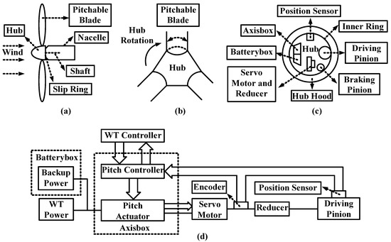
Figure 1.
Physical structure of the variable-speed pitch system: (a) side view of the hub; (b) front view of the hub; (c) perspective view of the hub; (d) schematic diagram of a pitch system.
Figure 1d introduces the overall structure of a pitch subsystem. Both the WT power and the batteries (or capacitors, as the backup power) provide direct current (DC) power and actuate the servo motor through a pitch actuator. The WT power can actuate to pitch both towards feather and fine, but the backup power can actuate to pitch towards feather only. The WT controller controls every pitch controller and exchanges data with them. The pitch controller, actuator, servo motor, and encoder form a control loop. The position sensor provides a correction for the encoder in the control.
3. Modeling and Variable-Speed Pitch Control
Theoretically, pitch control with a variable-speed pitch system for WTs is the process that adjusts the pitch angles of the blades. As shown in Figure 1d, the WT controller sends the reference pitch angles to the pitch controllers. To simulate the process, a WT model that includes both the aerodynamic components and the pitch control strategy is necessary. The modeling parameters are shown in Table 1.

Table 1.
Modeling parameters.
3.1. Wind Turbine Modeling
For an actual torque, the rotor speed can be maintained in proportion to the wind speed, which means that the optimum tip speed ratio is maintained, and the power coefficient is a maximum. The power coefficient indicates the fraction of the potential power in the wind, which can be converted by the WT. It has a theoretical maximum value of 59.3% (the Betz limit). In practice, perfectly tracking the optimum is always a target for the control performance of the pitch system. The aerodynamic model can be expressed as (1) and (2) [19]:
where P is the output power, is the aerodynamic torque, is the air density, R is the radius of a blade, is the wind speed, is the pitch angle, and is the tip speed ratio.
The dynamic response of can be expressed as (5) [17]:
where , , and denote the rotational inertia of the rotor, the accelerated speed of the rotor, the torque of the main shaft, and the damping coefficient of the rotor, respectively.
According to (2) and (6), the WT model is nonlinear. A linearized model is necessary for the pitch controller. At the optimum point, the Taylor series expansion of (6) can be expressed as (7) [17]. The subscript op denotes at the optimum point:
where .
Supposing and , (10) can be obtained and s is the Laplace operator. Then, (11) is deduced by (10) as a linearized model according to the Laplace transform [17]:
Supposing ,
3.2. Pitch Servo System
Figure 2 illustrates a typical pitch control system, including the PI controller, pitch servo, and a nonlinear turbine model [20]. The pitch servo system consists of the actuator and motor shown in Figure 1d. The pitch actuator is a nonlinear servo that generally rotates all of the blades or a part of them. In the closed loop, the pitch servo can be modeled as an integrator or a first-order delay system with a time constant . Equation (12) provides the dynamic behavior of this system [20]:
where , , and the subscripts min, max, and ref denote the minimum, maximum, and reference values, respectively.
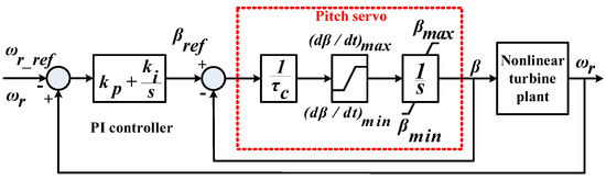
Figure 2.
Block diagram of a typical pitch control system.
3.3. Pitch Angle Control Strategy
Figure 3 illustrates the pitch control system with a linearized turbine model. The PI controller receives the reference and measured turbine rotational speed, that is, and , respectively, calculate the control error and generate the pitch angle reference signal . The pitch servo is also a closed-loop system that can rotate the pitch angle to track the reference signal. The adjusted pitch angle will move the turbine rotational speed to the reference value, and therefore eliminate the control error.

Figure 3.
Block diagram of the pitch angle control strategy.
For stability, the components of the terms in the transfer function need to be positive. If the optimum point is changed, the PI controller gains should be redesigned to maintain the dynamic response and stability of the system.
4. Control Scheme for ZVRT
By definition, the voltage dip at the PCC is a fault for WTs. However, the ride-through process requires WTs to not disconnect from the grid, based on the premise that the WTs are running safely. Therefore, the control scheme during a ZVRT or an LVRT for a WT is actually a safety control scheme in the fault status.
4.1. Design of Control Logic during an FRT
There are three control modes in the WT controller: normal, fast, and emergent modes; the latter two of which are used to deal with faults. In fast mode, the pitch system pitches towards feather. In emergent mode, the WT controller outputs an emergency feather command (EFC). The pitch system will not only feather to the limit but also ignore other commands until the WT stops and selflocks.
Many fault indicators are defined in the WT controller to reflect the operating status of the WT. Any high-level output from the indicators triggers the fault status, and the WT controller switches fast or emergent mode. The logic is shown in Figure 4. In particular, a turn-off delayer (TOF) is added after the OR logic operation, which contributes to maintaining the input of the TOF for 4 s. The sampling period in the WT controller is 20 ms. A total time of 4 s or 200 periods aims to ensure that there is sufficient time for communication, signal processing, and device action when the OR logic operation outputs a high level.
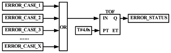
Figure 4.
The control logic of triggering the fault(error) status for WTs.
Different from other fault indicators, the 18 error variables shown in Table 2 indicate that the WT has been operated in an emergency and must be stopped and checked as soon as possible. As shown in Figure 5, the variables (from V1 to V18) control the nodes (from K1 to K18) of a safe loop. Any output variation of the variables indicates the breakup of a node, which would lead to an interruption of the loop and the emergent mode in the WT controller. The threshold values of the variables are shown in Table 3.
Table 2.
Error variables to interrupt the safe loop.
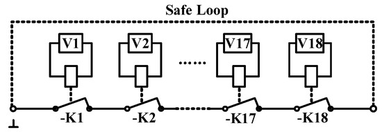
Figure 5.
Schematic diagram of the safe loop.
Table 3.
Threshold values of the fault variables.
For the pitch system, the three modes in a WT controller correspond to three feather methods (normal-feathering, fast-feathering, and emergent-feathering), which can be distinguished by the pitching (towards feather) speeds (4.0, 5.5 and 7.0 deg/s) and the feather limit (pitch angles: 89°, 89° and 91°). The normal-feathering method is used for a WT in normal operation. When the WT switches the fault status, the pitch system will adopt the fast-feathering method. The pitch system receives the control commands from the WT controller periodically in the normal-feathering and fast-feathering methods and adjusts the pitching actions immediately according to the commands. However, once the emergent mode is confirmed by the WT controller, the pitch system ignores all the commands, continues pitching towards feather until the pitch angle reaches 91°, and can only be unlocked manually, which means that the WT may have critical failures and should be analyzed carefully.
There are two types of power supplies for the pitch controllers of the WT power: DC 24 V and an uninterrupted power supply (UPS, DC 24 V). In normal mode, the pitch controller uses the WT power: DC 24 V, and the pitch actuator including the servo motor uses the WT power. In emergent mode, the pitch controller uses the UPS, and the pitch actuator uses the backup power. In fast mode, the pitch system generally uses the WT power unless the voltage of the WT power is lower than a threshold value. However, this fault will trigger more WT faults.
As mentioned previously, the control process by the control logic for LVRT (the existing design) can be described as follows. Once a low-voltage (LV) dip at the PCC is detected, the WT controller outputs an LVRT-starting signal, and the pitch system executes the fast-feathering method. During the LVRT, if the PCC voltage returns to normal, the WT controller outputs an LVRT-ending signal and a pitch angle based on Section 3.3; then, the pitch system pitches in normal mode. In this period, the pitch system generally runs on the WT power, the voltage of which is detected periodically.
However, the existing design will not work for the ZVRT condition. Once a ZV dip occurs, the WT controller does not recognize it as a clear LV dip, but cannot determine if it is a power-loss case, and thus, the safe loop is interrupted almost simultaneously.
Therefore, to ride through, the control scheme during a ZV dip has been improved. First, the voltage dips at the PCC are differentiated. Voltages at the PCC between 5% p.u. and 90% p.u. are regarded as an LV dip. When a ZV dip (the voltage at PCC is between 0% p.u. and 5% p.u.) is detected, the pitch system still acts by the fast-feathering method as with an LVRT within a certain time. The time is set to 1000 ms because the model in Article [12] theoretically simulates the maximum time of a ZVRT as nearly 950 ms. After this time, the uncleared ZV dip is regarded as a power-loss case, and the WT controller outputs an EFC. Second, to avoid the power-loss risk, the UPS and backup power are enabled as power supplies for the pitch controller and pitch actuator during a ZVRT. Third, the OPC system of WTs is redesigned to avoid the overspeed error in the rotor caused by untimely pitching.
4.2. Design of Control Circuit during an FRT
The control circuit is designed to execute the control logic in Section 4.1, which involves the WT controller, pitch controller, pitch actuator, and pitch power in Figure 1. For the pitch system, a major function of the control circuit is switching or selecting the power for the pitch actuator.
4.2.1. Control Circuit for LVRT
The LVRT control circuit is shown in Figure 6. Figure 6a introduces the control structure of a DC contactor. Contacts 1–4 are the main contacts. Contacts 11, 12, and 14 are auxiliary contacts. Contact 11 is a common port. Contact 12 is a normally closed (NC) contact. Contact 14 is a normally open (NO) contact. When Coils A1 and A2 operate, Contacts 1–4, 11, and 14 are synchronized to operate. Contact 12 executes a reverse action. Elements 6K3 and 5K1 in Figure 6b are DC contactors. 304S1 is a manual switch. Module KL2134 is a 4-channel digital output terminal for electrical isolation, which provides binary control signals [34]. KL2134 will output a high level when a combination of the following conditions is true. (1) The pitch angle reaches 91°. (2) The pitch actuator is fault-free. (3) The WT controller outputs a reset command. KL2134 and 304S1 together provide a bypass circuit. Figure 6c is the power-switching circuit of the pitch actuator (including the servo motor).
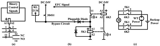
Figure 6.
Control circuit for LVRT. (a) schematic diagram of DC contactor; (b) control circuit for LVRT; (c) power switching circuit.
The control process can be described as follows. In normal mode, the EFC signal continuously outputs a high level. Contacts 11 and 12 of 6K3 operate. The A1 side of 5K1 receives the high level and Contacts 1–4 of 5K1 operate. At the same time, Contacts 11 and 12 of 5K1 release, which keeps A1, A2, and Contacts 1–4 of 6K3 released. The WT power is enabled for the pitch actuator.
When the safe loop is interrupted, the EFC signal outputs a low level. However, at the moment of interruption, Contacts 11 and 12 of 6K3 keep operating, which triggers A1 and A2 of 5K1 release. Then, Contacts 11 and 12 of 5K1 operate, and Contacts 1–4 of 5K1 release. Next, A1, A2, and Contacts 1–4 of 6K3 operate, and Contacts 11 and 12 of 5K1 release. Finally, the backup power is enabled, and the pitch system starts to feather in emergent mode. Using this design, 5K1 and 6K3 implement a mutex in the control logic.
As mentioned above, a safe loop interruption can only be restored manually. After the WT stops, the backup power will be enabled. When the fault is cleared, the WT power needs to be enabled for pitching towards fine. The bypass circuit in Figure 6b is designed for this power switching requirement, which aims to temporarily span the EFC signal. When 304S1 is closed, the bypass circuit outputs a high level to make A1 and A2 of 5K1 operate and finally enable the WT power (A1 and A2 of 5K1 operating causes Contacts 11 and 12 of 5K1 to release and Contacts 1–4 of 5K1 to operate. Then, A1 and A2 and Contacts 1–4 of 6K3 release.). KL2134 is actually a redundancy design for the bypass circuit. If it is verified that there is no fault for the WT and the emergent mode is triggered just because an EFC signal outputs incorrectly, KL2134 provides a remote-restoring method for the WT by resetting the WT controller. Conditions (1) and (2) for KL2134 outputting a high level particularly limit the scope of application of KL2134, which means that KL2134 outputs a high level only if the blade has reached a feather limit and there are no faults in the pitch system.
4.2.2. Flaw Analysis of Control Circuit for LVRT
A WT operating in Liaoning, China, collapsed on 6 May 2017, due to an LV dip. The cause analysis indicates conclusively that there were design flaws in the LVRT control circuit. The analysis process can be described as follows.
Figure 7 demonstrates the operating status of the WT at the moment of collapse based on data in the emergent record of the WT. The pitch angle of Blade 1 and the A-phase grid voltage are presented as examples of the pitch angles (of three blades) and 3-phase grid voltages. For convenience, all the actual values are converted to the p.u. values.
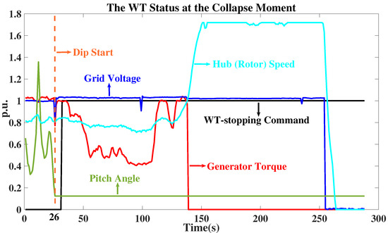
Figure 7.
The operating status of the WT at the moment of collapse. The p.u. values of the rotor speed, generator torque, pitch position, and grid voltage are 20.35 rpm, 100 N·m, 10°, and 380 V, respectively.
As shown in Figure 7, the grid voltage decreased to 0.8 p.u. at the 26th second, which triggered an LVRT starting signal. The dip also caused a voltage fluctuation of the WT power (The emergent record showed that the WT power fluctuated between 182.39 V and 400 V). According to the LVRT control logic, the threshold value triggering the pitch system to switch to backup power during an LVRT was set as 115 V. Therefore, the backup power was not enabled for the voltage fault of the WT power during the collapse.
Then, the WT controller outputted the pitch communication error in Table 2. After the safe loop was interrupted, the WT-stopping command outputted a high level. However, the pitch position revealed that the pitch system did not act, and the WT converter decreased the reference electromagnetic torque of the DFIG in a timely manner. Next, the rotor speed increased to more than 1.7 times the upper limit, and the WT controller output the overspeed error, grid disconnection error, high temperature of the winding in the generator, and high temperature of the bearing of the generator in this order. Finally, the transmission system of the WT disintegrated, the blades broke, and the WT went offline from the monitoring system. The collapse process lasted 250 s (after 250 s, most of the curves returned to zero, which meant that the WT had already collapsed), and the largest rotor speed of the generator was over 3500 rpm.
The immediate cause of the accident was the overspeed error in the rotor. The model in Section 3.1 is used to simulate an extreme case. Suppose that Blade 2 and Blade 3 cannot pitch due to faults. The results in Figure 8 indicate that the rotor speed would be held at a safety level even if there was only one blade that could be feathered. Then, it could be concluded that any one of the feathered blades would effectively decrease the rotor speed, which means the pitching load is reasonable.
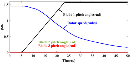
Figure 8.
Simulation results of the extreme case of the WT in an accident. The p.u. values of the pitch angle and rotor speed are 58.20° and 9.3 rad/s, respectively.
To further analyze this example, all the wrecked devices of the pitch system in this accident were detected carefully. The key point occurred when KL2134 continuously outputted a high level because the inner signal channel short-circuited. As shown in Figure 6, if KL2134 outputs a high level incorrectly and continuously, A1, A2, and Contacts 1–4 of 5K1 continue operating, which prevents Contacts 1–4 of 6K3 from operating, and the backup power cannot be enabled. When the WT power could not provide the power for pitching during the LV dip, the pitch system thoroughly lost power for pitching and could not feather.
4.2.3. Improved Control Circuit for ZVRT
It is probable that inner damage occurred to all modules. Thus, the flaw is not a faulty KL2134 module that should be replaced but a design flaw in which the control circuit lacks safety redundancy.
The control circuit in Figure 6b is redesigned for the bypass circuit and the (signal) input part. As shown in the red box in Figure 9, DC contactors 1K1 and 2k3 are added in the bypass circuit, and their structures are shown in Figure 6a. Contacts 1–4 are the main contacts of 1K1. Module KL1104 is a 4-channel digital input terminal for electrical isolation, which detects the input level periodically as a monitor [35]. The conditions of KL2134-1 outputting a high level are identical with those of KL2134 in Figure 6b. However, the condition of KL2134-2 outputting a high level is that the WT controller provides a ZVRT-ending command. 208F9 is an air switch to isolate the UPS from the contacts.
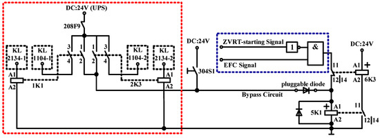
Figure 9.
Improved control circuit for ZVRT.
When KL2134-1 outputs a high level according to the WT power command, A1, A2, and Contacts1–4 of 1K1 operate, and the bypass circuit outputs a high level from DC:24V (UPS). When KL2134-1 outputs a high level incorrectly and continuously, KL1104 will continuously detect the high level from DC:24V (UPS). To emphasize this point, both the WT controller command and fault will make KL2134-1 output a high level, but the reset command from the WT controller will be maintained for 4 s, which has the same design as that shown in Figure 4. KL1104 only detects a high level if the time is longer than 4 s, and it would output a high level for the WT controller, which means that KL2134-1 has been damaged.
KL2134-2 is added for the ZVRT-starting signal in the blue box in Figure 9. When the ZVRT-starting signal outputs a high level, the backup power will be enabled. However, when the ZVRT status ends, the WT power needs to be enabled for pitching towards fine. The WT controller outputs a ZVRT-ending signal that lasts for 4 s for KL2134-2, and KL2134-2 outputs a high level. 2K3 and KL1104-2 act in the same way as 1K1 and KL1104-1.
5. Overspeed Protection Control (OPC)
Section 4.1 indicates the importance of overspeed protection during a ZVRT. The overspeed protection during a ZVRT provides a necessary safety redundancy for WTs to respond to power-loss risks and not-pitching failures. The pitch system is exactly the executor of OPC.
The existing OPC scheme is shown in Figure 10. Sensors are installed in different locations in the nacelle and measure different types of rotor speeds, such as the shaft speed and the rotor speed in the generator. The OPC1 module is installed in the WT controller cabinet and receives the rotor speed data from the sensors. If any rotor speed is beyond the threshold value, the OPC1 module will send an overspeed signal to the WT controller. Then, the WT controller will interrupt the safe loop and output an EFC to the pitch controller. The EFC signal will output a low level to enable the backup power (explained in Figure 6) because the NC contact K1 turns to open. However, the OPC devices in the existing scheme are far away from the pitch system in the structure, which produces a substantial amount of long-distance signal transmission. Section 4.2.2 and Appendix B confirm that there may be some failures in the long-distance signal transmission, which will eventually lead to not-pitching failures. Furthermore, in the control logic during a ZVRT, the pitch system will pitch by the fast-feathering method in the first 1000 ms. If the ZV dip is exactly a power-loss situation, the pitch system might lose communication and power supply after 1000 ms, resulting in an overspeed risk.
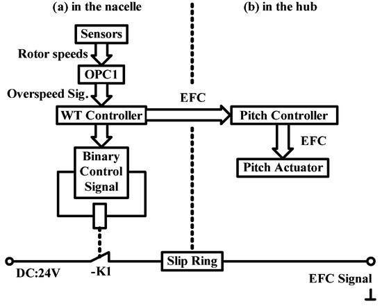
Figure 10.
The existing OPC scheme.
Therefore, an improved OPC scheme is proposed, as shown in Figure 11. For the improved scheme, three sensors are installed in the hub to measure one type of rotor speed, the hub speed. A new OPC module (OPC2) separated from the WT controller is designed and installed in the pitch controller cabinet in the hub, which is directly connected with the pitch controller. The OPC2 module receives the rotor speed data from the three sensors. Once it outputs an overspeed signal, the pitch controller will interrupt the safe loop immediately, although the overspeed signal has been sent to the WT controller at the same time. The OPC2 module provides an additional protection for WTs, compared with the existing OPC scheme. The pitch controller in the improved scheme has a greater control authority, and the control process based on the OPC2 module will occur in the hub only, which can effectively reduce failures.
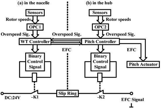
Figure 11.
The improved OPC scheme.
The three photoelectric sensors (proximity switches) and corresponding limit irons used to locate the sensors need to be embedded in the hub. They are 120° apart from each other. The installation diagram is shown in Figure 12, and Figure 13 shows the installation of the OPC2 module in the pitch controller cabinet.
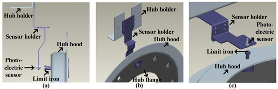
Figure 12.
Installation diagram of sensors and mechanical devices. (a) is the lateral view, (b) is the front view, and (c) is a perspective drawing.
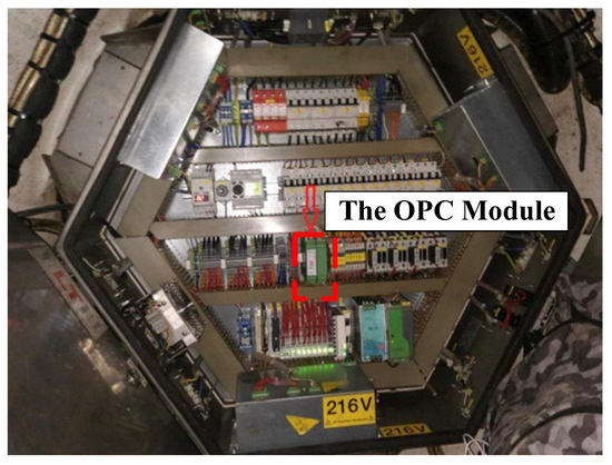
Figure 13.
Installation diagram of the OPC2 module in the pitch controller cabinet.
The control logic of the OPC2 module is shown in Figure 14. Every sensor provides a speed and a state, which indicates whether or not it is working normally in a sampling period. Three speeds will be transferred as three overspeed states as the inputs in Figure 15 [26].
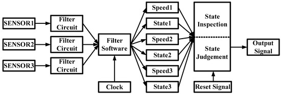
Figure 14.
The control logic of the OPC2 module.
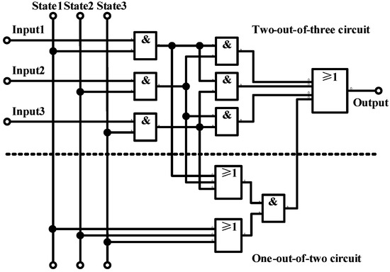
Figure 15.
The improved 2-out-of-3 circuit.
An improved 2-out-of-3 circuit is used in the state judgement in Figure 14. If two high levels of the three overspeed states are detected, the module will output a high level (overspeed signal). Furthermore, a 1-out-of-2 circuit is added in the 2-out-of-3 circuit, the control logic of which is if one of the three incorrectly working sensors, and one high level in the two remaining overspeed states will trigger a high level of the module output. If two sensors work incorrectly, the OPC2 will send an overspeed signal directly.
6. Validation and Test Results
The effectiveness validation of the holistic control scheme is based on laboratory tests and field tests. The laboratory tests are used to test the OPC function in Section 5 and validate the effectiveness of the control circuit in Section 4.2.3. The pitching performance of a WT is evaluated during a ZVRT (simulating an overspeed condition on an operating WT is definitely forbidden). The field tests are used to validate the effectiveness of the control logic in Section 4.1 during a ZVRT.
First, a set of rotor speeds is inputted into the OPC2 module. As shown in Figure 16, the rotor speeds continue increasing linearly until reaching 20.35 rpm (1.17 p.u.) in the first 11.5 s, remain unchanged for the next 10 s, and then decrease linearly to 0. The EFC-triggering curve in Figure 16 illustrates that the module can output a correct command (an overspeed signal), interrupt the safe loop in time, and hold the command even if the rotor speeds decrease in the last 11.5 s, which means that the module could execute a required OPC function.
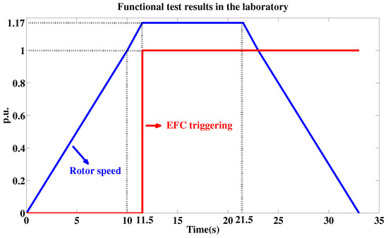
Figure 16.
Functional test results of the new OPC module in the laboratory. On the y-axis, a value of 1 for the EFC triggering indicates the high level, and the p.u. value of the rotor speed is 17.4 rpm.
Second, a laboratory test, as shown in Figure 17, is conducted. The laboratory test could simulate the power-loss condition (the three-phase voltages at PCC dip to 0%, approximately). The dragging motor is to simulate the condition (torque) of pitching one blade. The pitch actuator is installed under the pitch controller in the axisbox. The model, which runs on a computer (not shown in Figure 17), simulates the WT controller using the pitch angle control strategy in Section 3.3, and the control logic in Section 4.1.
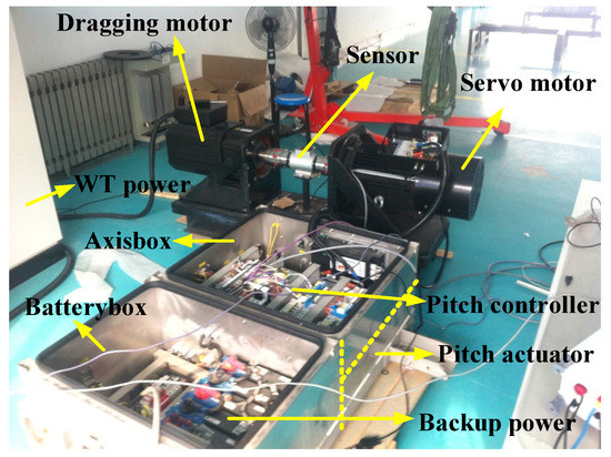
Figure 17.
Schematic diagram of the laboratory test.
The test also selects a set of field data (such as the wind speed curve in Figure 18). To meet the field conditions, the threshold value of triggering an overspeed signal in OPC2 module is temporarily reset to 15 rpm. Therefore, a wind speed reaching 0.5 p.u. will trigger an EFC at the moment of 0 s in Figure 18. All pitch angles for the three blades reach 91° in 10 s, proving the effectiveness of the control circuit in Section 4.2.3 and the OPC system. The following performance of the three pitch subsystems is even beyond the design requirement. The reference pitch angle rises from 0° to 72° in the 10 s, which means that the reference pitching speed is nearly 7 deg/s. However, the actual pitching speed can reach nearly 9 deg/s because any pitching speed greater than 7 deg/s will be encouraged in the emergent mode. The WT controller will output a fault only for a value less than 7 deg/s.
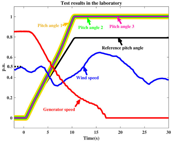
Figure 18.
Test results in the laboratory. The p.u. values of the pitch angle, generator speed and wind speed are 91°, 1750 rpm and 11 m/s, respectively.
Finally, an operating WT in Hebei, China, is transformed with the holistic control scheme, and then a field test of ZVRT is conducted according to the test method suggested by IEC [30] (the ZV conditions are simulated according to Figure 19). The ride-through period is defined as 430 ms according to the South Australian standard [32], which is the strictest in the world [12]. The active power of the WT shown in Figure 20 indicates that the WT has ridden through a ZV dip successfully and not triggered the emergent mode during ZVRT. The pitch angle in Figure 20 verifies that the pitch system does execute a feather command at the start of the ZV dip and a fine command at the end of the ZV dip successfully according to the control logic in Section 4.1.
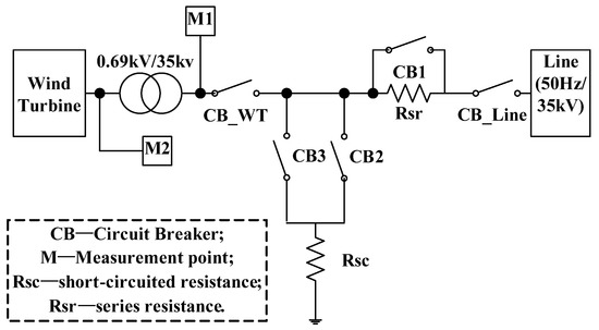
Figure 19.
The method of the ZVRT field test.
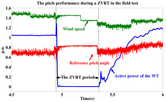
Figure 20.
Results of the field test. The p.u. values of the reference pitch angle, active power, and wind speed are 10°, 2 MW and 10 m/s, respectively. The fault condition is a three-phase (symmetrical) voltage dip.
The results of the laboratory and field tests demonstrate the effectiveness of the holistic control scheme and that it satisfies the ZVRT requirements for a WT. The control scheme also has the advantage of contributing to improving the grid-connection capability of WTs, as described in Section 1.
7. Conclusions and Future Work
The early work for this study confirmed that the control scheme with the variable-speed pitch system for WTs during a LVRT cannot satisfy the ZVRT requirements because the WT controllers using this scheme cannot distinguish a ZVRT status from a power-loss condition.
This paper first proposes a holistic control scheme for the pitch system during a ZVRT that mainly includes the control logic programmed into the WT and pitch controllers, some control circuits, and the OPC system. According to the test results, the proposed control scheme perfects the fault response technology and improves the grid-connection performance for WTs. The following additional conclusions can be made:
(1) It is highly important to model the mechanical devices in the aerodynamic and pitch systems to simulate the pitching process. The aerodynamic parameters in Table 1 are used to calculate the torque of pitching the blade, which is the basis of simulating the pitching process. The parameters of the pitch driver (servo motor) in Table 1 should match the torque.
(2) If the blade in Table 1 was replaced with a larger one (the aerodynamic parameters were changed), the pitching torque would be increased. It would be hard for the pitch driver in Table 1 to pitch the larger blade. The pitching speed in test results would be decreased and the pitching time would be longer, which meant a worse pitching performance. Conversely, the pitching speed would be increased in a certain extent and the pitching time would be shorter, which meant a better pitching performance.
(3) Monitoring and protective devices are critical for the primary control circuits in WTs. Control device damage is unavoidable during operation, but incorrect outputs of the primary control circuits can lead to emergencies. Therefore, the stability of the control device should be reconsidered when WTs are operating (or are about to operate) in extreme environments (high-temperature, high-humidity, high-dust, etc).
Some limitations of this study and future work are summarized as follows:
(1) Further observation and research on the adaptability and robustness of the control scheme, supported by more data from long-running systems under various external environments and grid conditions would be useful. It is suggested that several WTs be equipped with the proposed scheme in an environment to suppress occasional interference.
(2) The emergent-feathering performance of WTs should be tested periodically using the control scheme with a pitch system. An improved test method is provided in the Appendix B.
Author Contributions
Conceptualization, E.C.; methodology, E.C. and Y.Y.; software, E.C.; validation, E.C.; writing—original draft preparation, E.C.; writing—review and editing, L.D. and X.L. All authors have read and agreed to the published version of the manuscript.
Funding
This research received no external funding.
Conflicts of Interest
The authors declare no conflict of interest.
Abbreviations
The following abbreviations are used in this manuscript:
| ZVRT | Zero-voltage ride through |
| LVRT | Low-voltage ride through |
| FRT | Fault ride through |
| WT | Wind turbine |
| OPC | Overspeed protection control |
| PCC | Point of common coupling |
| ZV | Zero-voltage |
| LV | Low-voltage |
| RSC | Rotor-side converter |
| GSC | Grid-side converter |
| DC | Direct current |
| PI | Proportional integral |
| PID | Proportional-Integral-Derivative |
| EFC | Emergency feather command |
| TOF | Turn-off delayer |
| UPS | Uninterrupted power supply |
| NC | Normally closed |
| NO | Normally open |
| IEC | International Electrotechnical Commission |
| IEEE | Institute of Electrical and Electronics Engineers |
Appendix A. Standard Grid Codes for LVRT and ZVRT

Figure A1.
Standard curves in grid codes for LVRT and ZVRT. The LVRT and ZVRT curves shown using the grid codes for China and South Australia [32,36].

Appendix B. Regular Test Method of Emergent-Feathering
It is stipulated in the WT design documents that the emergent-feathering performance must be tested regularly. The period is usually three months or half a year. The common method is to interrupt the safe loop intentionally to simulate an emergency and then to observe the pitch performance.
On 25 December 2018, a 3 MW WT operating in Hebei, China, could not feather during the test until the UPS in the WT controller was cut off in the emergency. After analysis, the accident might be correlated with the design flaws in Section 4.2. The accident process can be summarized as follows. First, two signal slides, the EFC signal in Figure 6 and 24 V UPS, were connected in the slip ring (the slip ring of a WT has limited space but a complicated wiring design and is a mechanical rotating device, and thus breakover errors are typically unavoidable). Then, when the safe loop was interrupted, the WT disconnected from the grid, which meant that the WT lost electromagnetic torque. Finally, driven by the mechanical torque, the aerodynamic system of the WT rotated with an overspeed, and the operating status is shown in Figure A2.

Figure A2.
The operating status of the WT at the fault moment. The p.u. values of the electromagnetic torque, generator speed, rotor(hub) speed, and wind speed are 4300 N*m, 1200 rpm, 12.9 rpm, and 10 m/s, respectively.

Figure A2 also shows that the rotor speed will double in approximately 70 s for the conditions of losing the electromagnetic torque and not-pitching, even if the wind speed is very low (nearly 4 m/s).
Overall, the improved test method is suggested as follows on the condition that the wind speed is less than 6 m/s and there is no rain.
(1) Stop the WT, lock the hub with bolts, check the pressure of the hydraulic pressure station, and pitch just one blade towards fine to 0° manually using the WT power.
(2) Press the EFC button in the WT controller cabinet, which also enables the backup power for the pitch system.
(3) Measure the capacitor voltages or battery impedances in the backup power.
(4) Repeat the above steps two times, and draw three feather curves in one plot for three blades (the x-axis represents the feather time, and the y-axis records the pitch angle, such as Figure 18).
The qualified performances can be defined as follows.
(1) Three pitch angles have finally reached 91°.
(2) The entire feather time is less than 15 s. It will be also acceptable that the feather times in two tests are both less than 17 s, and all pitch angles reach 91°. When the air temperature is below −20 °C, the limit of 17 s can be broadened to 21 s, but the capacitor voltages or battery impedances should meet the requirements.
(3) The feather curves should be smooth, and the following performance should satisfy the requirement that the differences among the pitch angles should be less than 10° at any moment.
References
- Zhu, D.; Zou, X.; Deng, L.; Huang, Q.; Zhou, S.; Kang, Y. Inductance-emulating control for DFIG-based wind turbine to ride-through grid faults. IEEE Trans. Power Electron. 2017, 32, 8514–8525. [Google Scholar] [CrossRef]
- Chang, Y.; Hu, J.; Tang, W.; Song, G. Fault Current Analysis of Type-3 WTs Considering Sequential Switching of Internal Control and Protection Circuits in Multi Time Scales During LVRT. IEEE Trans. Power Syst. 2018, 33, 6894–6903. [Google Scholar] [CrossRef]
- Zhang, Y.; Melin, A.; Djouadi, S.; Olama, M.M.; Tomsovic, K. Provision for Guaranteed Inertial Response in Diesel-Wind Systems via Model Reference Control. IEEE Trans. Power Syst. 2018, 33, 6557–6568. [Google Scholar] [CrossRef]
- Liu, R.; Yao, J.; Wang, X.; Sun, P.; Pei, J.; Hu, J. Dynamic Stability Analysis and Improved LVRT Schemes of DFIG-Based Wind Turbines During a Symmetrical Fault in a Weak Grid. IEEE Trans. Power Electron. 2020, 35, 303–318. [Google Scholar] [CrossRef]
- Yang, L.; Xu, Z.; Østergaard, J.; Dong, Z.Y.; Wong, K.P. Advanced control strategy of DFIG wind turbines for power system fault ride through. IEEE Trans. Power Syst. 2012, 27, 713–722. [Google Scholar] [CrossRef]
- Shen, Y.; Ke, D.; Qiao, W.; Sun, Y.Z.; Kirschen, D.S.; Wei, C. Transient Reconfiguration and Coordinated Control for Power Converters to Enhance the LVRT of a DFIG Wind Turbine With an Energy Storage Device. IEEE Trans. Energy Convers. 2015, 30, 1679–1690. [Google Scholar] [CrossRef]
- Yang, S.; Zhou, T.; Chang, L.; Xie, Z.; Zhang, X. Analytical method for DFIG transients during voltage dips. IEEE Trans. Power Electron. 2017, 32, 6863–6881. [Google Scholar] [CrossRef]
- Guo, W.; Xiao, L.; Dai, S.; Li, Y.; Xu, X.; Zhou, W.; Li, L. LVRT Capability Enhancement of DFIG With Switch-Type Fault Current Limiter. IEEE Trans. Ind. Electron. 2015, 62, 332–342. [Google Scholar] [CrossRef]
- Cheng, M. Research on the Key Technologies of Low Voltage Ride through for Doubly-Fed Wind Power Generation System. Ph.D. Thesis, Shanghai Jiao Tong University, Shanghai, China, 2012. [Google Scholar]
- Ouyang, J.; Xiong, X. Electro-Magnetic Transient Analysis in Doubly-Fed Wind Generation Systems, 1st ed.; Science Press: Beijing, China, 2018. [Google Scholar]
- Zhu, D.; Zou, X.; Zhou, S.; Dong, W.; Kang, Y.; Hu, J. Feedforward current references control for DFIG-based wind turbine to improve transient control performance during grid faults. IEEE Trans. Energy Convers. 2018, 33, 670–681. [Google Scholar] [CrossRef]
- Zhao, H. The Research of Zero Voltage Ride Through Strategy of DFIG. In Proceedings of the IET International Conference on Renewable Power Generation (RPG 2016), London, UK, 21–23 September 2016. [Google Scholar]
- Zhao, H.; Tang, H.; Zhang, W.; Wen, W.L. Transient Characteristics Research and Integrated Control Strategy of DFIG for Zero Voltage Ride Through. Power Syst. Technol. 2016, 40, 1422–1430. [Google Scholar]
- Tang, H.; Chang, Y.; Chi, Y.; Wang, B.; Li, Y.; Hu, J. Analysis and Control of Doubly Fed Induction Generator for Zero Voltage Ride Through. In Proceedings of the 19th International Conference on Electrical Machines and Systems (ICEMS), Chiba, Japan, 13–16 November 2016. [Google Scholar]
- Cai, E.; Jiao, C.; Wang, D.; Jing, J.; Huang, F.; Pan, F. Test scheme of zero voltage ride through capability for DFIG-based wind turbines. Autom. Electr. Power Syst. 2016, 40, 137–142. [Google Scholar]
- Zhang, C. Research on Individual Variable Pitch Control Strategies of Large-Scale Wind Turbine. Ph.D. Thesis, Shenyang University of Technology, Shenyang, China, 2011. [Google Scholar]
- Dou, Z. Research on Individual Pitch Control for Large-Scale Wind Turbine. Ph.D. Thesis, Shanghai Jiao Tong University, Shanghai, China, 2013. [Google Scholar]
- Burton, T.; Jenkins, N.; Sharpe, D.; Bossanyi, E. Wind Energy Handbook, 2nd ed.; John Wiley & Sons: Chichester, UK, 2011. [Google Scholar]
- Zhang, Y.; Melin, A.; Djouadi, S.; Olama, M. Performance guaranteed inertia emulation for diesel-wind system feed microgrid via model reference control. In Proceedings of the 2017 IEEE Power&Energy Society Innovative Smart Grid Technologies Conference(IGST), Washington, DC, USA, 23–26 April 2017. [Google Scholar]
- Van, T.; Nguyen, T.; Lee, D. Advanced pitch angle control based on fuzzy logic for variable-speed wind turbine systems. IEEE Trans. Energy Convers. 2015, 30, 579–587. [Google Scholar] [CrossRef]
- Jafamejadsani, H.; Pieper, J. Gain-Scheduled ℓ1-Optimal Control of Variable-Speed-Variable-Pitch Wind Turbines. IEEE Trans. Contr. Syst. Technol. 2015, 23, 372–379. [Google Scholar] [CrossRef]
- Chen, P.; Han, D.; Tan, F.; Wang, J. Reinforcement-Based Robust Variable Pitch Control of Wind Turbines. IEEE Access 2020, 8, 20493–20502. [Google Scholar] [CrossRef]
- Tang, X.; Yin, M.; Shen, C.; Xu, Y.; Dong, Z.Y.; Zou, Y. Active Power Control of Wind Turbine Generators via Coordinated Rotor Speed and Pitch Angle Regulation. IEEE Trans. Sustain. Energy 2019, 10, 822–832. [Google Scholar] [CrossRef]
- Chirca, M.; Dranca, M.; Teodosescu, P.; Breban, S. Limited-Angle Electromechanical Actuator for Micro Wind Turbines Overspeed Protection. In Proceedings of the 2019 11th International Symposium on Advanced Topics in Electrical Engineering (ATEE), Bucharest, Romania, 28–30 March 2019. [Google Scholar]
- Wen, L.; Sheng, W.; Xu, Z. Research on overspeed protection control strategies of PWR nuclear power units. In Proceedings of the 2019 IEEE Innovative Smart Grid Technologies-Asia (ISGT Asia), Chengdu, China, 21–24 May 2019. [Google Scholar]
- Ji, J. On Fail-safety Control Technology of 1000 MW Steam Turbine for Nuclear Power Plants and its Application. Master’s Thesis, Shanghai Jiao Tong University, Shanghai, China, 2018. [Google Scholar]
- Wang, L.; Zhao, J.; Liu, D.; Wang, J.; Chen, G.; Sun, W.; Qi, X. Governor tuning and digital deflector control of Pelton turbine with multiple needles for power system studies. IET Gener. Transm. Distrib. 2017, 11, 3278–3286. [Google Scholar] [CrossRef]
- Mellal, M.; Chebouba, B. Cost and Availability optimization of Overspeed Protection System in a Power plant. In Proceedings of the 2019 International Conference on Advanced Electrical Engineering (ICAEE), Algiers, Algeria, 19–21 November 2019. [Google Scholar]
- IEEE 1865.1-2019. IEEE Standard Specifications for Maintenance and Test of Distributed Control Systems in Thermal Power Stations: Maintenance and Testing; IEEE: Piscataway Township, NJ, USA, 2019. [Google Scholar]
- IEC 61400-21-1:2019. Wind Energy Generation Systems—Part 21-1: Measurement and Assessment of Electrical Characteristics—Wind Turbines; IEC: Geneva, Switzerland, 2019. [Google Scholar]
- IEEE 1159-2019. IEEE Recommended Practice for Monitoring Electric Power Quality; IEEE: Piscataway Township, NJ, USA, 2019. [Google Scholar]
- South Australian Minister. National Electricity Rules, Version 142; AEMC: Sydney, Australia, 2020.
- Northern Territory Minister. National Electricity Rules as in Force in the Northern Territory, Version 52; AEMC: Sydney, Australia, 2020.
- Module Introduction–KL2134. Available online: https://www.beckhoff.com/english/bus_terminal/kl2134.htm (accessed on 19 July 2017).
- Module Introduction–KL1104. Available online: https://www.beckhoff.com/english/bus_terminal/kl1104.htm (accessed on 19 July 2017).
- GB/T 19963. Technical Rule for Connecting Wind Farm to Power System; SAC: Beijing, China, 2016. [Google Scholar]


© 2020 by the authors. Licensee MDPI, Basel, Switzerland. This article is an open access article distributed under the terms and conditions of the Creative Commons Attribution (CC BY) license (http://creativecommons.org/licenses/by/4.0/).