Abstract
In this study, we investigate a numerical-modeling method uniquely performing analyses of 50 different metal hydrides to find the optimized thermal effect. This paper presents a metal-hydride thermal energy conversion method, which offers an alternative approach to the traditional vapor-compression heat pump associated with conventional heating, ventilation, and air conditioning (HVAC). The authors have developed an innovative heat pump applicable to non-vapor compression-based systems, which are in compliance with low-temperature heat source requirements for operation. The new heat pump has a high-energy savings potential for both heating and cooling that featured two different metal-hydrides, that are distributed inside parallel channels filled with porous media. Thermal energy conversion is developed as a set of successive thermal waves. The numerical-modeling results present the enhanced thermal effect, which is attained in a synchronous motion of the thermal waves and the heat source (or sink) inside paired porous media channels, which accompanies the phase transition in the succession of unit metal-hydride heat pumps. The results present in a form convenient for the prediction of thermal energy efficiency based on the proposed thermal-conversion method in real devices that were experimentally verified in previous work. The non-vapor technologies will be operational with low energy input, which makes it possible to utilize waste heat or low-level heat often found in the environment such as solar radiation, exhaust gas from a heat engine, or high-temperature fuel cell system.
Keywords:
metal-hydride; heat pump; porous media; thermal wave; temperature; HVAC; non-vapor compression 1. Introduction
The increasing daily environmental issues on earth have encouraged us to develop environmentally-friendly technologies in the broad fields of science and industrial areas. Particularly, chlorofluorocarbons (CFCs) emitting from a vapor compression type of heating, ventilation, and air conditioning (HVAC) system or a refrigerator, cause problems not only in the local environment but also in the global environment. It has been gradually restricted in its applications to 38 industrialized nations since the Montreal Protocol was established in 1987 by the United Nations Environment Programme [1,2]. Thus, it is not necessary to emphasize the research and development (R&D) efforts, which preceded finding a new activation fluid and developing a cooling mechanism without using CFCs such as the non-vapor-compression systems. However, the conventional HVAC systems still heavily rely on the principle of the vapor-compression, which has shown some critical environmental and cost issues. Thus, more affordable and practical non-vapor compression technologies have been determined as necessary in the energy and HVAC area. This is because, according to a DOE report, none of the non-vapor priority technologies seem to satisfy most of the desired requirements and ultimate directions set by DOE, including cost-effectiveness, system complexity, reliability issue, and technical maturity [3].
The non-vapor technologies should be operational with low energy input, which makes it possible to utilize waste heat or low-level heat often found in the environment. Examples of this type of heat can come from several sources, such as solar radiation or possibly exhaust gas from a heat engine or from a high-temperature fuel cell system. Most importantly, these non-vapor technologies should be applicable to both space heating and cooling.
There is a need to develop a new system that may provide not only the environmentally friendly advantage of avoiding CFC consumption but also effective usage of thermal energy. The reaction enthalpy of metal hydrides in the range of 30 to 80 kJ/mol·H2 is reasonably higher than the phase transition energy of H2O (40 kJ/mol) or CFCs (6 kJ/mol). The thermodynamic cycle of a metal hydride heat pump (MHHP) system was developed by Argonne National Laboratory in 1979 and became popular worldwide [4]. The MHHP keeps the typical advantages of a sorption-type chemical-heat pump while avoiding their disadvantages, such as system complexity and a limited temperature ranges due to the material characteristics of reaction agent (i.e., water and LiBr or NH3). In addition, the R&D protocol of the metal hydride system offers a wider prospect of hydrogen energetics. Controlling the metal hydride pairs makes the system possible to determine the hydrogen storage capacity, operating temperature, and pressure. This type of control also provides good reversibility that allows the heat pump system to operate under various input heat sources/sink temperatures. However, it still has some critical issues in practical applications due to the irreversible heat loss caused by the bulky metal reactor and metal hydride powder itself, which has a very low thermal conductivity level of glass or ceramic material but with significantly high hydrogen reaction rate [5].
To avoid the critical challenges of the metal hydride system as defined thus far, several researchers have proposed a metal hydride thermal conversion system that employs a heat exchange between the metal hydride reactor and a thermal wave, which propagates into an adiabatic porous media with a highly developed surface area [6,7]. In this study, we investigate the numerical-modeling method to find an optimized pair of metal hydrides for the suggested system using synchronous motions of the thermal waves in the heat source and heat sink inside paired porous media channels. Uniquely we perform numerical analyses on the thermodynamic cycle performance of the metal hydride thermal energy conversion system elaborating the superadiabatic condition composed by 122 combinations of metal hydride pairs using 50 different metal hydrides. This paper also presents the prediction of the thermal effectiveness of the proposed thermal-conversion method in a laboratory setup that has been experimentally verified in previous research efforts.
2. Mathematical Model
2.1. Thermodynamic Characteristics of a Metal Hydride
Metal hydrides are a unique type of alloys, which can absorb and desorb hydrogen reversibly, while releasing and absorbing thermal energy, respectively. Absorbing and desorbing hydrogen is the fundamental working principle presented in this article. Many metals and alloys react reversibly with hydrogen to form metal hydrides according to the following reaction:
where Me is a metal, solid solution, or intermetallic compound. MeHx is the respective hydride, and x is the ratio of a hydrogen atom to metal, Q is the quantity of heat (kJ).
Since the entropy of the hydride is lowered in comparison to the metal and the gaseous hydrogen phase at ambient and elevated temperatures, the hydride formation is exothermic, while the reverse reaction of hydrogen release is accordingly endothermic [8]. The reaction equilibrium can be described by the van’t Hoff expression:
where is equilibrium pressure of hydrogen (atm); is the atmospheric pressure (1 atm); R is the ideal gas constant (J/(mol·K)); T is temperature (K); is the enthalpy (J/ mol·H2), and is the entropy of the metal hydride (J/mol·H2·K).
We collected thermodynamic equilibrium properties of 50 well-defined metal hydrides from various publications (see references in Table 1). Those properties helped us to apply the alloys and metals in a performance prediction of the thermal energy conversion system, and its thermodynamic properties are represented in Table 1. The table shows the enthalpy and the entropy changes that measured when a metal hydride in the desorption process. The number of each metal hydrides and its order in Table 1 are based on its integration values, as noted in Equation (2) among temperatures ranging from −100 °C to 400 °C, in order to select an appropriate metal hydride in the specific temperature and pressure range.

Table 1.
Thermodynamic equilibrium properties of metal hydrides reported in various peer-reviewed journal articles. is reaction enthalpy, and is reaction entropy measured in the desorption process.
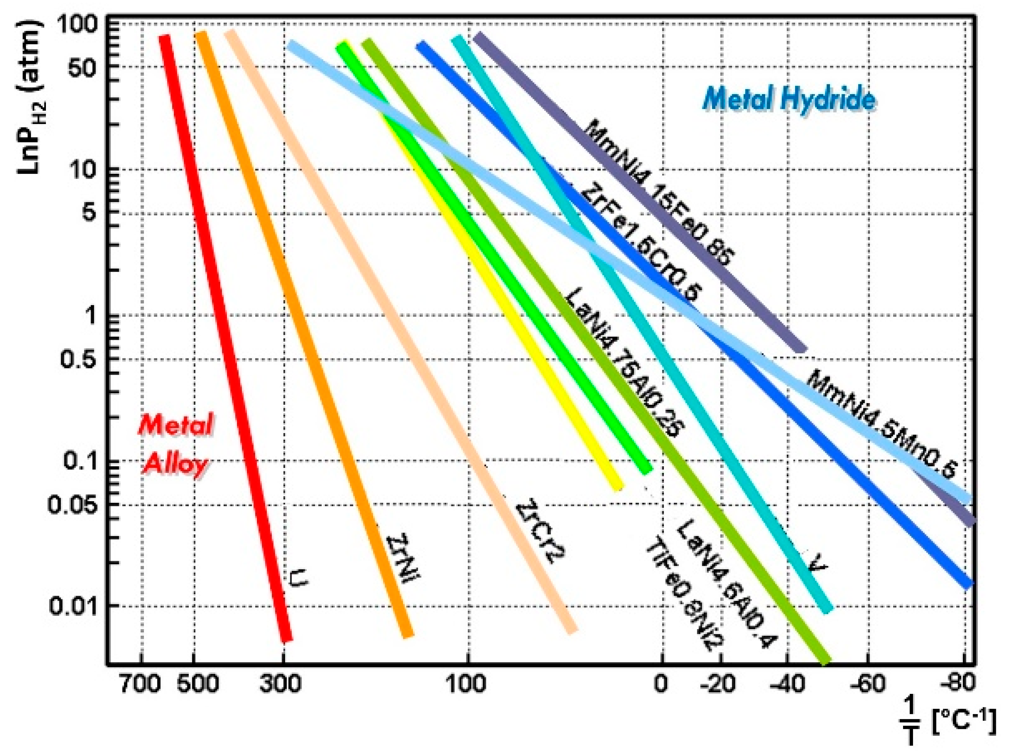
Figure 1 shows some examples of the van’t Hoff plot, which presents a relationship between the equilibrium hydrogen pressure and the temperature of each metal hydride alloy as the relationship relates to a scale, according to Equation (2) and Table 1. For different metal hydrides, the reaction enthalpy, and the reaction entropy, are represented by the slope and intercept, respectively. In the estimation of the van’t Hoff plot, the metal and hydrogen keep in dissociated status in the lower-left condition while it forms a metal hydride status in the upper-right condition for each metal hydride as shown in Figure 1.

Figure 1.
Metal hydride materials with their equilibrium temperature and pressure on the van’t Hoff plot demonstrates a wide range of temperature selections for an application of the metal hydride thermal energy conversion system.
2.2. Thermodynamic Cycle of a Metal Hydride Heat Pump (MHHP)
According to the plot in Figure 1, various metal hydrides are distributed in a wide range of temperatures. It indicates that the system can operate flexibly in three distinct thermodynamic cycles: cooling, heat pump, and conversion of low-grade heat to high-grade heat (heat upgrade cycle), based on metal/hydrogen interaction characteristics and choice of a metal hydride alloy pair having different thermodynamic properties of the reaction enthalpy and entropy. The system can be modified for varying input waste-heat temperature sources by adjusting the metal hydride pairs. The performance of the system does not require any environmentally harmful chemicals or materials.
To operate the MHHP cycle based on the equilibrium thermodynamic characteristics of the metal hydride, at least one pair of metal hydride alloys with different equilibrium temperatures at a given pressure has to be selected. One with higher equilibrium temperature is referred to as “HT” and the other to “LT” of the subscript letter in this paper (Figure 1, Figure 2, Figure 3 and Figure 4). Figure 2 (left) shows the actual metal hydride reactor pair used in the experimental setup in the MHHP system illustrated in Figure 4 [7]. The two reactors filled with different metal hydride alloys, and that allow cyclical hydrogen exchange through the tube fittings between the reactor pair. The vertical part of the tube fitting with a valve is prepared to charge hydrogen initially. Figure 2 (right) is the thermodynamic cycle diagram of an MHHP system illustrated in the van’t Hoff plot [4]. cycles between temperatures and with corresponding equilibrium pressures of hydrogen at States 1 and 2. cycles between temperatures and where its corresponding equilibrium pressures of hydrogen are at States 3 and 4, respectively.
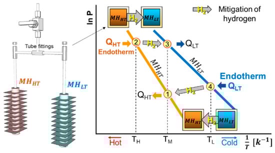
Figure 2.
The actual metal hydride reactor pair used in the experimental setup shown in Figure 4 (left); The thermodynamic cycle diagram of an MHHP system illustrated on the van’t Hoff plot for an arbitrary metal hydride pair (right). The numbers in the red circle indicate each state. The arrows connecting States 2–3 and States 4–1 indicate the hydrogen migration between the reactors with relevant endotherm and exotherm.

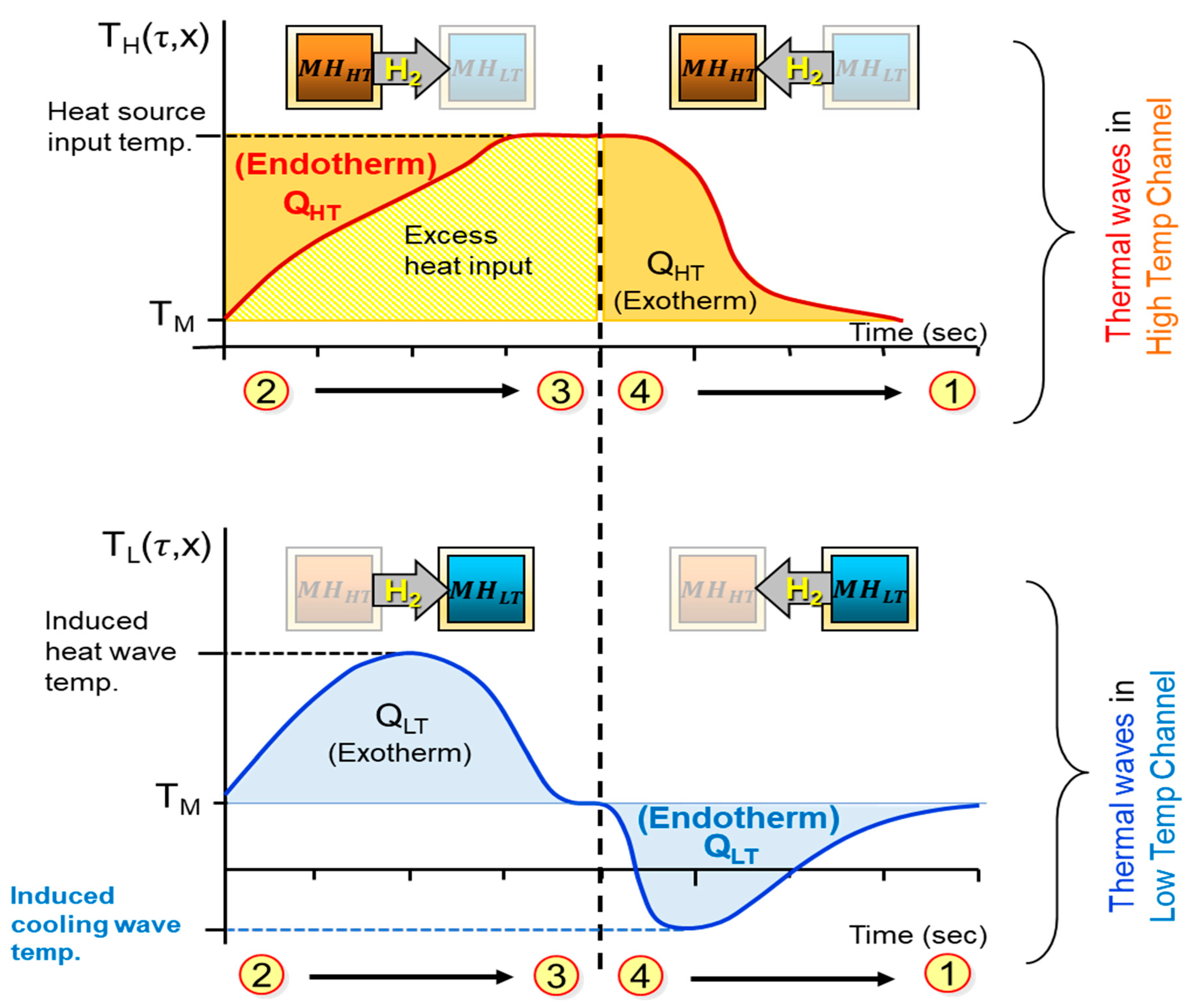
Figure 3.
An illustration of thermal energy conversion wave (TECW) formation: TECW in red is from reactor (top); and TECW in blue is from reactor (bottom). The endotherm is the objective cooling load in the cooling system.
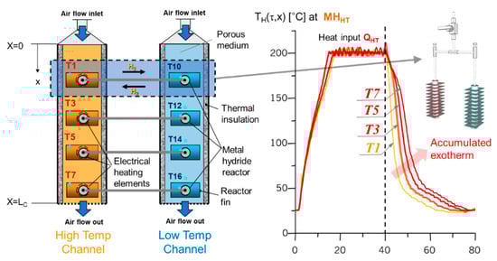
Figure 4.
Metal hydride thermal energy conversion system with an arrayed dual metal hydride heat pump (MHHP) reactor pair units (left); the laboratory setup configuration is for the verification test of the system inducing superadiabatic TECW (right). Experimental results of the superadiabatic TECW is induced by deploying arrayed dual metal hydride reactor pairs in an adiabatic porous media. The temperature profiles, T1–T7, show the temperature variation over time in each location of the high-temperature channel (left), demonstrating the effectiveness of the configuration on the formation of TECW accumulating-induced heat.
The MHHP cycle is driven by heat input to at the high-temperature , thereby desorbing hydrogen. Hydrogen flows to which absorbs it and releasing the absorption exotherm at the medium temperature level (first half cycle). In the second half cycle, there is the heat input to at a low-temperature , which is the cooling load. The endotherm QHT is the most important in the cooling system. This heat is upgraded to a higher temperature level by desorption at . Then hydrogen flows to , where it is absorbed, releasing absorption exotherm QHT at TM.
The ideal coefficient of performance, , of the cycle can be described by the relationship between the reaction enthalpy of the metal hydride pair as follows:
where is the reaction enthalpy of the , and is the reaction enthalpy of the .
However, in the actual performance of the cycle, each quantity of heat, , and is distributed to the metal hydride alloy bulk and reactor. Thus, the possible quantity of heat charged by each metal hydride alloy bulk is:
and:
where is a mass, and is the heat capacity of metal hydride alloy bulk. Furthermore, the charged heat from reactors should be considered. The possible quantity of heat charged by each reactor can be expressed as:
and:
where is mass, and is heat capacity of a reactor; therefore, the overall quantity of heat during the cycle operation can be expressed as follows:
and:
where is the amount of hydrogen gas that interacts with the metal hydride alloy bulk during the cycle operation (mole). Accordingly, the actual COP of cooling () should be defined as follows considering the metal hydride alloy bulk and reactors:
2.3. A Metal Hydride Thermal Conversion System with Superadiabatic Thermal Energy Conversion Waves (TECWs)
The metal hydride thermal conversion system is theoretically a highly efficient system. Compared to other heat pump systems, high productivity and efficacy in space cooling and heating of buildings can be achieved by using a waste heat source/sink and without the introduction of harmful materials used in conventional sorption systems [56]. In addition, the dual (or binary) metal hydride system can be modified to accept various temperatures of heat sources and sinks by properly selecting metal hydride pairs. However, there are two critical challenges of the MHHP system in actual practice; the first problem is caused by a comparably high reaction rate between metal hydride alloy and hydrogen but with very low heat conductivity. The second problem is oriented irreversible loss of reaction heat potential due to thermal mass, as shown in Equations (4)–(7), which involves heat exchange between the metal hydride system and heat carrier. These critical challenges delay the heat exchange between the metal hydrides and heat carrier. Accordingly, desorption heat offers a reasonably high cooling effect up to −100 °C [57]. However, it is also possible to gain a low-grade cooling effect that operates at only 10–30 °C below the mean temperature level. Research efforts have been made to tackle the drawback by advancing the MHHP reactor design and configuration [58,59,60,61]. Nonetheless, the prevention of thermal energy dissipation into the ambient environment is still challenging; thus, the overall useful amount of produced thermal effect is always lower than the theoretical expectations stated in Equation (3). The challenge is to transfer the released heat/cold as fast as possible with small gradients to a desired heat transfer fluid [59]. Managing the thermal effect is the key to efficient hydrogen storage [61]; thus, knowledge of transient heat and mass transfer in a deformable metal hydride bed is essential.
To address the challenges, Fateev and Rabinovich introduced the heat exchange mechanism based on an adiabatic porous medium where the reaction exotherm and endotherm are collected in the form of thermal wave and propagated by the stream of heat carrier [62]. In this mechanism, the amplitude of the thermal wave is increased by accumulation of reaction exotherm and endotherm when the MHHP reactors (shown in Figure 2 left) are arrayed along the length of the porous media channel as shown in Figure 4 and react subsequently by the propagation of the thermal wave. As shown in Figure 3 (bottom), it is important to keep a certain distance between the leading exotherm wave and the following endotherm wave to maximize the accumulation of the thermal effects leading a superadiabatic condition and to avoid an offset interference of the waves.
To properly realize the TECW mechanism, experimental tests were performed deploying a series of MHHP (as shown in Figure 2 left) units arrayed in an adiabatic porous media channel to ultimately induce superadiabatic conditions shown in Figure 4 (left) [7]. An air-blower is applied to provide the air stream as a heat carrier with specific flow rates. The multiple metal hydride reactors with MHHT located in the high-temperature channel equipped with an independent electrical heating element to provide heat input . Several thermocouples are installed inside of the porous media channels and on the surface of reactors’ fin to measure temperature profiles of TECW. Some other thermocouples are placed inside of the reactor to measure the equilibrium temperature of metal hydride alloy bulk.
The porous media channel is expected to form a superadiabatic TECW. In particular, thermal energy becomes accumulated inside the channel, which makes it possible to overcome the heat loss to ambient conditions. Figure 4 (right) shows the effect of superadiabatic conditions that are producing efficiently induced heat (in the right part of red and yellow-orange thermal waves in the figure) by heat source input.
The figure illustrates a testing configuration for synthetic superadiabatic conditions (i.e., high-temperature airflow using an electrical heating element in the high-temperature channel and ambient temperature airflow moving through the low-temperature channel in the same direction while exchanging thermal energy induced by hydrogen migration.
Figure 5 shows the most important results that demonstrate the formation of induced heating and objective cooling effects (targeted temperature) by a pair of AB2 type metal hydrides of Zr0.9Ti0.1Cr1.0Fe1.0–Zr0.9Ti0.1Cr0.6Fe1.4. The former is used for and the latter for . The system was successfully able to produce both the 60 °C of heating and −15 °C of cooling in the low-temperature channel by use of heat input at 200 °C in the high-temperature channel.
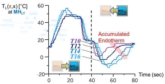
Figure 5.
Experimental results of induced exotherm and endotherm by the reactors in the low-temperature channel (right channel). The result verified the formation of leading heat and following objective cooling effect by use of the original heat source input at high-temperature channel shown in Figure 4 right. The accumulated endotherm by arrayed reactors of metal hydride heat pump with superadibatic condition.
2.4. Heat Transfer Model for Parametric Study
Kim [6] developed theoretical heat transfer models of the superadiabatic TECW propagation in a thermally activated porous media. This paper describes the thermodynamic relationship between the adiabatic temperatures of high- and low-temperature channels and the heat transfer between the reaction heat of unit metal hydride heat pumps and the gas flow as a heat carrier in adiabatic porous media. The numerical-modeling method applied in this study is based on a one-dimensional quasi-steady-state thermodynamic model. The thermal inertia in porous media is not considered in the model. A heat transfer modeling for the superadiabatic thermal wave propagation in the thermally activated porous media applied in the thermodynamic model is:
and:
where, are velocity (m/sec), density (kg/m3) and specific heat (W/m3∙°C) respectively, T is heat carrier gas temperature, x is coordinate from the channel entrance (m), is time (sec), is thermal conductivity (W/m∙°C), w is internal heat source (W/m3) originated to the metal hydride reaction enthalpy when the subscript letter p denotes for porous media, g for heat carrier gas, HT for the high-temperature channel where the reactors are arrayed, and LT for the low-temperature channel where the reactors are arrayed.
The internal heat source , and are modeled as following equations by introducing ranging between 0 and 1 as a hydrogenation degree of metal hydride contained inside of arrayed reactors in the low-temperature channel. is also representing a preparation degree of the dual MHHP reactor pair unit, and it comes to 1 when it is situated at State 4 after it passes the first-half cycle and about to start the second-half cycle in Figure 2 according to the working principle of the metal hydride thermodynamic cycle. The hydrogenation degree of metal hydride in the high-temperature channel is assumed :
and:
where, is the volumetric heat transfer coefficient between metal hydride alloy and porous media, is temperature of metal hydride alloy bulk based on the equilibrium temperature defined in van’t Hoff equation (see Equation (2)). The adiabatic temperature used in Equations (13) and (14) is implicating the idea specified by Equations (8) and (9) and modeled as follows:
where, is a number of the dual MHHP units arrayed in the channel, is the amount of hydrogen associated with metal hydride alloy bulk (mole), is reaction enthalpy of metal hydride (kJ/mol·H2), m is mass (kg), c is specific heat (W/m3∙°C) when the subscript m denotes for metal hydride alloy bulk, r for reactor and p for porous media. The relationship between the adiabatic temperatures of high- and low-temperature channels, according to Equation (15) is:
and according to the Equations (13)–(16):
The temperature of metal hydride alloy bulk , and are derived by Equation (2):
and:
where, the quasi-steady-state assumption that the equilibrium hydrogen pressure inside of both high- and low-temperature reactors are assumed to be the same at each finitely divided time fragments () is applied. The velocity of the superadiabatic thermal wave propagating into the porous media channel is referred to the free thermal wave velocity defined by following expressions:
The induced cooling effect is a form of a thermal wave that is collected at the outlet of the porous media channel; therefore, its specific cooling power per unit area of the channel cross-section and COP must be estimated by the range of desired temperature level. Therefore, the cumulative amount of induced cooling effect is evaluated with an integrated quantity of endotherm for cooling in a range between the heat carrier gas temperature of induced cooling at the end of the channel as shown in Figure 4 (right), and the ambient mean temperature , which is expressed as:
where x is the location inside the channel from 0 to (m), is the gas velocity (m/sec); ρ is the density (kg/m3), c is the specific heat (J/(kgK)); is the time when the becomes lower than the objective cooling temperature , and is the time when it becomes higher than . Based on this study, the specific cooling power and the final considering a superadiabatic TECW propagation and thermally activated porous media of the system, we can determine the specific cooling power (12) and final (13) as:
and:
where is a time duration of heat input in the high-temperature channel.
3. Numerical Calculation Results and Discussion
3.1. Selecting the Hydride Pair
The setting up of the operating temperature range for the system is established with a specific temperature: the 20 °C of the ambient mean temperature () and the 320 °C of heat source gas temperature (). These make up the porous media, and the high temperature represents the requirement of the unit heat pumps of the high-temperature channel in a thermally activated status; moreover, the −50 °C temperature that is set to be a maximum achievable temperature and is down 70 °C from the . It is necessary to select the proper metal hydride pair as they must satisfy the following two conditions: (1) They must provide an efficient reaction with hydrogen at a temperature range from 20 °C to 320 °C in the high-temperature channel and from −50 to 20 °C in the low-temperature channel; (2) they must prove proper of the the reactor at 320 °C, which must be higher than the reactor at 20 °C, and the equilibrium hydrogen pressures of the reactor at −50 °C must be higher than the the reactor at 20 °C, according to the principle of the thermodynamic cycle of the MHHP (as shown in Figure 2).
The arbitrary selection of the is made among the list of metal hydrides that interact with hydrogen in the comparatively higher temperature range for the parametric study such as the No. 37, No. 38, No. 40, No. 41, and No. 42 metal hydrides from Table 1. The selection of an to match the must be according to their van’t Hoff plot criteria of a geometrical consideration. This narrows the options to a number between No. 3 and No. 25 for the No. 37. For the No. 38, the options are between No. 2 and No. 26. For the No. 40 and No. 41, the options are between No. 3 and No. 28. For No. 42, the options are between No. 7 and No. 28. The van’t Hoff plot indicates 122 possible pairs of metal hydrides to organize a heat pump/cooling cycle in the selected temperature range of the system operation.
To choose optimized hydride pair among the selected possible hydride pairs, the computer code based on the mathematical model is performed. Those hydride pairs are selected with the efficient cooling effect up to −50°C with a higher than others. For the calculation of the metal hydride pairs, initial input parameters are shown in Table 2 from the previous study [9], which was performed by the LaNi4.5Al0.5-MmNi4.15Fe0.85 pair.
Table 2.
The design and operation parameters.
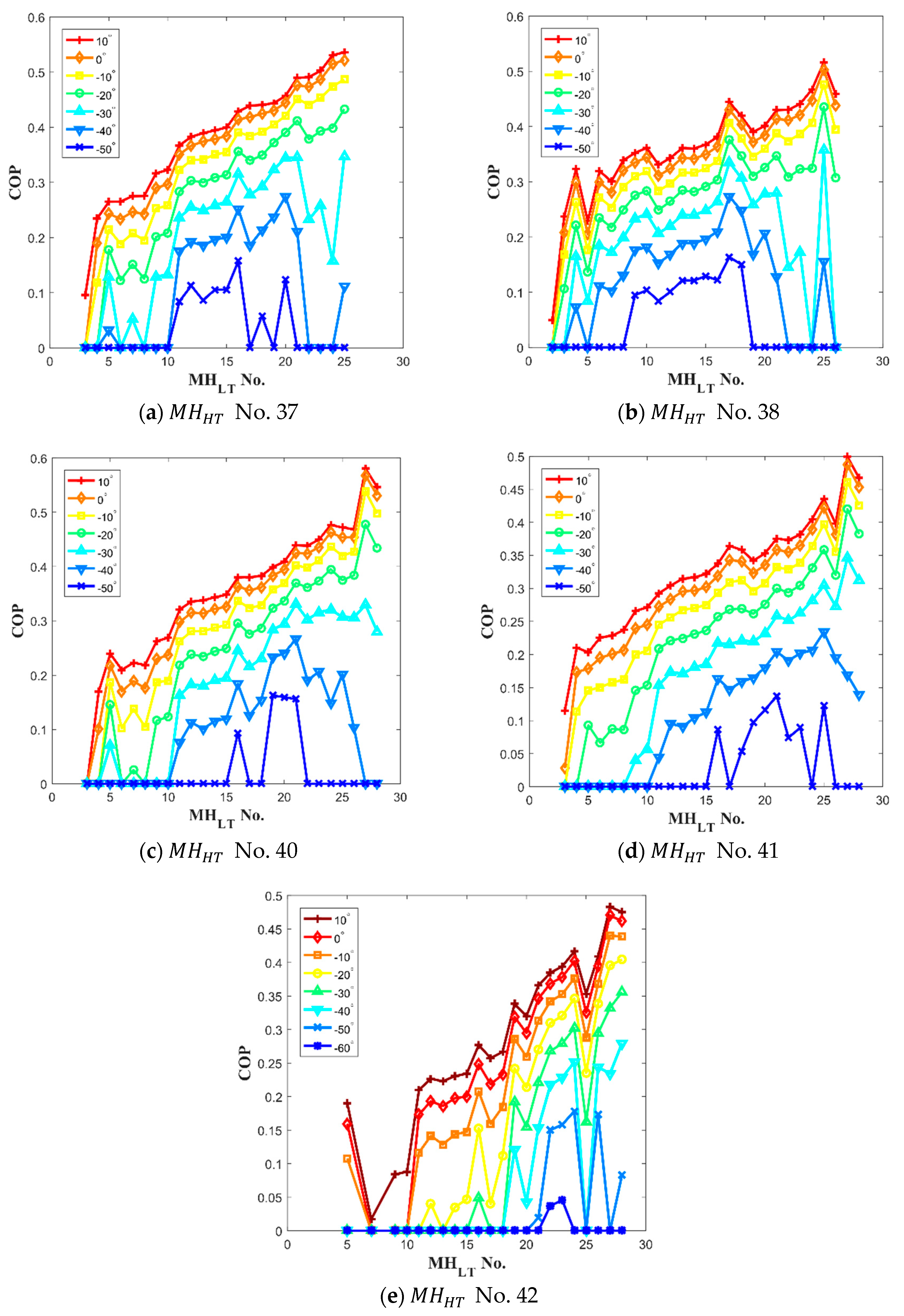
The results of the numerical calculation from Equation (24) provide the based on the induced heat of cooling in a range between objective cooling temperature () and ambient mean temperature () for each hydride pair as show in Figure 6. At −50 °C of the cooling temperature, a few reactors showed a high value. The high values at the lowest temperature indicate that the system using the optimized pairs can operate at the lowest cooling temperature. For example, only No. 11 to No. 16 for No. 37 can generate the lowest temperature shown in Figure 6a. In addition, among those , No. 16 shows the highest value as shown in Figure 6a. The results in Figure 6a–e clearly show specific optimized pairs having the highest value at −50 °C of the cooling temperature.
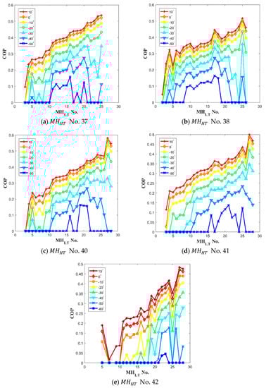
Figure 6.
The calculation result of with each hydride paired to of (a) No. 37; (b) No. 38; (c) No. 40; (d) No. 41; and (e) No. 42. The results provide a base to select the best hydride pairs to the various objective cooling temperatures.
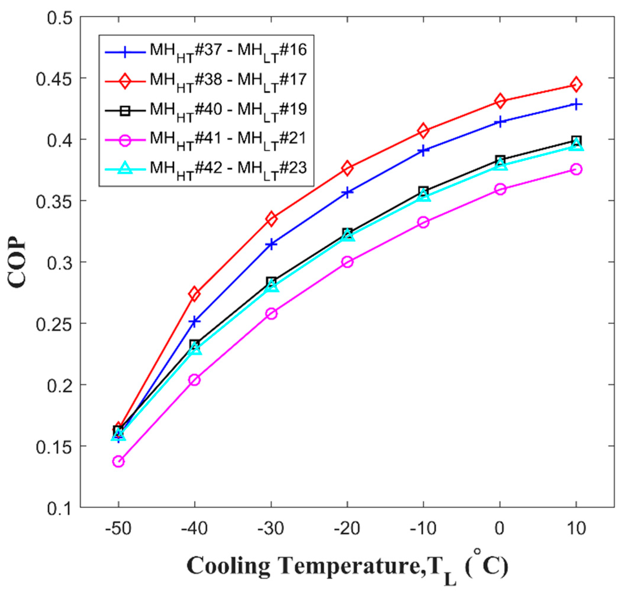
Each optimized hydrogen pair for and are No. 37-No. 16, No. 38-No. 17, No. 40-No. 19, No. 41-No. 21, and No. 42-No. 23. Notably, No. 5 shows exceptionally high value with No. 42 as shown in Figure 6e while the value of No. 5 are low with other . It is because the value affected by not only enthalpy but also entropy that chanced by specific .The calculated from Equation (24) of each high hydrogen pair at the various objective cooling temperatures, is presented in Figure 7. According to the results, the hydrogen pair of No. 38-No. 17 provides the highest at the most of the desired cooling temperatures, and the hydrogen pair of No. 42 and No. 23 presents the lowest cooling temperature of up to −60 °C. Thus, among the parametric study results, the hydrogen pair of No. 38-No. 16 show the best performance.
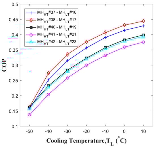
Figure 7.
of the optimized pairs. Each optimized hydride pair shows a different performance with a different objective cooling temperature, .
3.2. Design and Operation Parameters of the Thermal Conversion System
The effect of the channel length and the gas velocity in both channels are presented to review the performance of the proposed metal hydride thermal conversion system. For the analysis, the hydrogen () pair, No. 38-No. 15 (LaNi4Al-TiV0.62Mn1.5) are selected among high results with initial input parameters shown in Table 2.
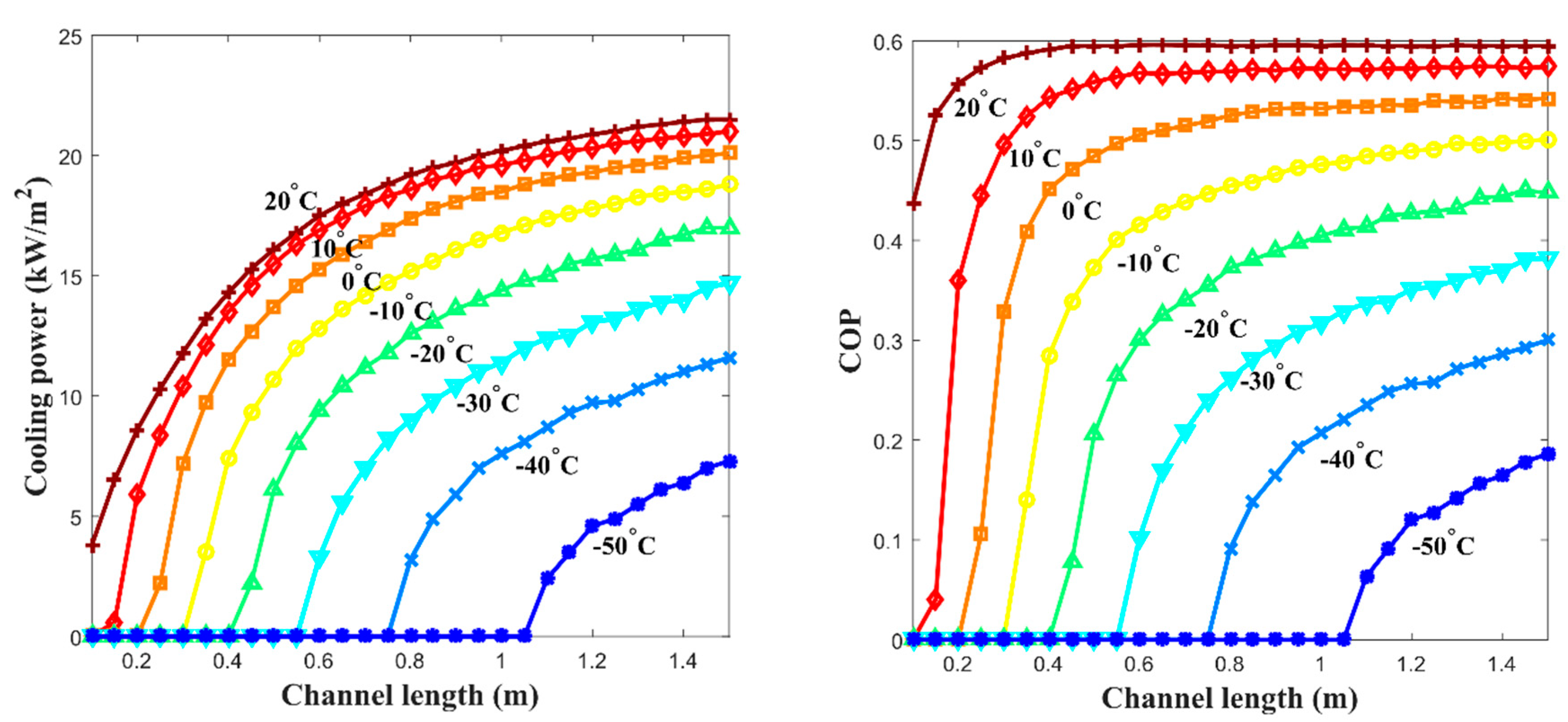
The and the specific cooling power with various channel lengths were calculated and obtained with the results shown in Figure 8 when the free thermal wave velocity of 10 cm/min that is in linear proportion to the gas velocity is applied. 30 °C of the is applied in the calculation of Equations (23) and (24). There is a certain elevated temperature of thermal wave propagation formed by the exotherm of the absorption process from the reactor channel (a leading elevated temperature wave) before the propagation of the induced effective thermal wave of cooling in the low-temperature channel. Therefore, it is important to design the channel length to keep the proper distance between the leading elevated temperature wave and the following low-temperature wave. For instance, when the channel length is too short, the following low-temperature wave goes just behind the leading elevated temperature wave, and both waves get into reciprocal action during their propagation into the low-temperature channel, which drives the operation results into the reduction of the wave amplitudes at the end of the channel where the cooling effect has to be gathered. On the contrary, when the channel length is too long, there are no certain positive gains to the or the specific cooling power since its cycle frequency is made longer, which eventually drives the net power of the system into a lower level. According to the calculations, it is estimated that 0.9~1 m of the channel length provides the optimized output of the system, as shown in F.
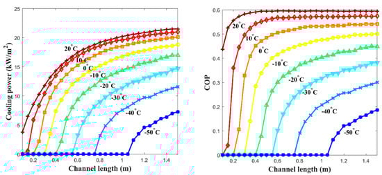
Figure 8.
Performance of the proposed metal hydride thermal conversion system is shown based on the effect of channel length: (left) the at various channel lengths; and (right) the specific cooling power at various channel lengths. Both plots directly indicate that channel length affects the performance of the system.
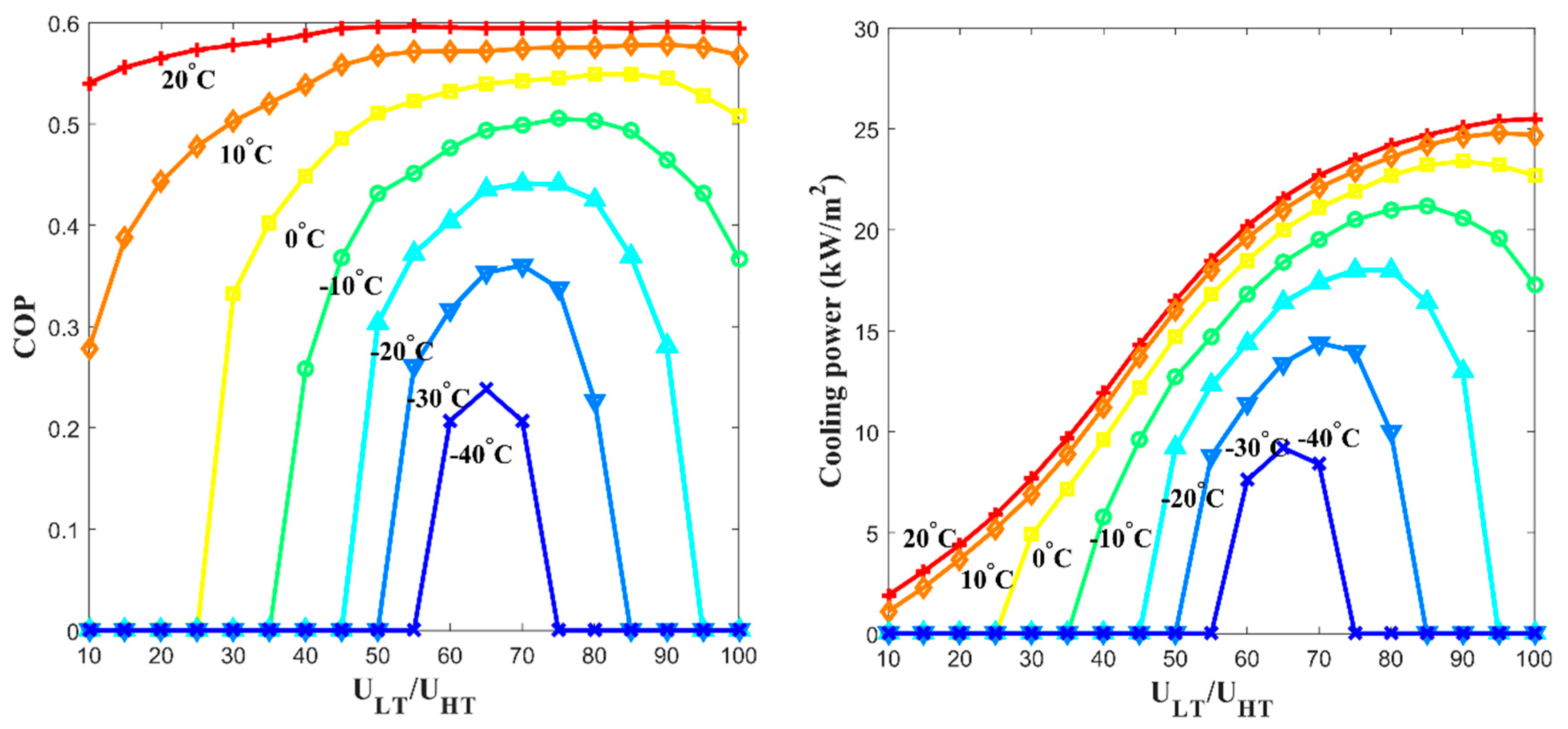
Figure 9 presents the calculation results of the and specific cooling power when the system varies the ratio of the free thermal wave velocity in the low-temperature channel to the one in the high-temperature channel (/). When the velocity in the low-temperature channel was 65% of the velocity in the high-temperature channel, the best and specific cooling power were obtained among most of the cooling temperature range.
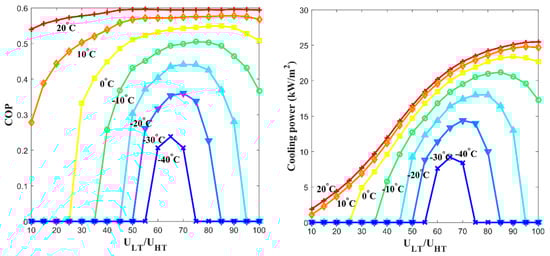
Figure 9.
Performance of the proposed metal hydride thermal conversion system affected the ratio of the free thermal wave velocity in the low-temperature channel to the corresponding velocity in the high-temperature channel (/), which affected the (left) ; and (right) specific cooling power at various ratios between free thermal wave velocities.
Notably, reached to 0.6 of (=∆hL/∆hH) for the selected hydride pair when the cooling effect, is −10 °C. Our experimental results indicate that the critical problem of the traditional metal hydride thermal conversion system caused by the irreversible heat loss was overcome by the proposed system.
4. Conclusions
The presented study mainly focuses on a numerical study to estimate the thermodynamic cycle performance of the metal hydride thermal energy conversion system elaborating the superadiabatic condition composed by 122 combination of metal hydride pairs using 50 different metal hydrides. The authors’ new metal hydride thermal energy conversion system is applied by using the heat exchange between the arrayed MHHP reactor pair units and the thermal wave propagation in a porous media in order to enhance the thermal conversion effectiveness by avoiding the irreversible heat loss. The thermal energy conversion system presented in this paper is using a novel heat transfer mechanism that operates a superadiabatic thermal wave with hydrogen gas as the working fluid to generate reaction exotherm and endotherm. The achievements are noted in the following conclusion.
- The chosen hydride pair of LaNi4Al [10] and TiV0.62Mn1.5 [11], provided the highest cycle performance among the other pairs, achieving the cooling effect by high-temperature gas input at 320 °C and the ambient mean temperature of 30 °C according to the calculation results.
- The specific cooling power; 16.4 kW/m2 at −20 °C, 9.2 kW/m2 at −40 °C was achieved by parametric study results when the channel length is 1 m, the free thermal wave velocity at the high-temperature channel is 10 cm/min, and the free thermal wave velocity at the low-temperature channel is 6.5 cm/min. If the cross-sectional area of the channel is 0.04 m2 (=20 cm × 20 cm), each calculated power is 656 W and 368 W. It was shown that the proposed system’s amount of specific cooling power could be beneficial in an actual application.
- In the case of 10 °C and −20 °C of the cooling effect () from the ambient mean temperature at 30 °C, each of the proposed system was 0.59 and 0.57, which is similar to the ideal of the selected pair. It seemed that the heat exchange between the arrayed MHHP units and the propagation of the thermal wave contributes to the improvement of the metal hydride thermal conversion performance.
The system suggests a new possibility of its application as an air conditioning and refrigeration mechanism, which offers not only the environmentally friendly advantage of avoiding CFC consumption but also the advantage of effective thermal energy usage, since the mechanism can be operated by the waste thermal energy from homes, industries or automobiles. Therefore, the thermal energy conversion system presented in this paper for a novel heat pump system leveraging metal hydride thermochemistry has a high potential to meet a non-vapor compression system’s performance requirements.
Author Contributions
S.K. studied numerical simulation results, S.H. studied numerical simulation, analyzed the collected, and improved the manuscript draft, and K.-J.K. designed and supervised the study, reviewed and improved the manuscript draft. All authors have read and agreed to the published version of the manuscript.
Funding
This research received no external funding
Conflicts of Interest
The authors declare no conflict of interest.
References
- Sarma, K.M.; Bankobeza, G.M.; Mulumba, M.A. The Montreal Protocol on Substances that Deplete the Ozone Layer United; Ozone Secretariat: Nairobi, Kenya, 1990. [Google Scholar]
- Yang, L.; Jiang, W.; Ji, W.; Mahian, O.; Bazri, S.; Sadri, R.; Badruddin, I.A.; Wongwises, S. A review of heating/cooling processes using nanomaterials suspended in refrigerants and lubricants. Int. J. Heat Mass Transf. 2020, 153, 119611. [Google Scholar] [CrossRef]
- Goetzler, W.; Zogg, R.; Burgos, J.; Hiraiwa, H.; Young, J. Energy Savings Potential and RD & D Opportunities for Commercial Building HVAC Systems. 2017. Available online: https://www.energy.gov/sites/prod/files/2017/12/f46/bto-DOE-Comm-HVAC-Report-12-21-17.pdf (accessed on 5 May 2020).
- Sheft, I.; Gruen, D.M.; Lamich, G.J. HYCSOS Chemical Heat Pump and Energy Conversion System Based on Metal. Hydrides; Argonne National Lab: Lemont, IL, USA, 1979.
- Lototskyy, M.; Sekhar, B.S.; Muthukumar, P.; Linkov, V.; Pollet, B.G. Niche applications of metal hydrides and related thermal management issues. J. Alloy. Compd. 2015, 645, S117–S122. [Google Scholar] [CrossRef]
- Kim, K. Propagation of Waves of Metal-Hydride Thermal Conversion in Blown-Through Porous Media. J. Eng. Phys. 1998, 71, 1–11. [Google Scholar] [CrossRef]
- Fateev, G.A.; Silenkov, M.A.; Kim, K. Experimental Investigation of The Propagation of Heat Waves of Energy Conversion in Blown-through Porous Media. J. Eng. Phys. 2000, 73, 1069–1081. [Google Scholar]
- Dornheim, M. Thermodynamics of Metal Hydrides: Tailoring Reaction Enthalpies of Hydrogen Storage Materials. In Thermodynamic Properties of Metal Hydrides. Thermodynamics—Interaction Studies—Solids, Liquids and Gases; InTech: London, UK, 2011. [Google Scholar]
- Johnson, J.R.; Reilly, J.J.; Reidinger, F.; Corliss, L.M.; Hastings, J.M. On the Existence of F.C.C. TiCr1.8H5.3. J. Less Common Met. 1982, 88, 107–114. [Google Scholar] [CrossRef]
- Vogt, T.; Reilly, J.J.; Johnson, J.R.; Adzic, G.D.; McBreen, J. Crystal Structure of NonstoichiometricLa(Ni,Sn)5+x Alloys and Their Properties as Metal Hydride Electrodes. Electrochem. Solid State Lett. 1999, 2, 111–114. [Google Scholar] [CrossRef]
- Klyamkin, S.N.; Verbetsky, V.N.; Karih, A.A. Thermodynamic particularities of some CeNi5-based metal hydride systems with high dissociation pressure. J. Alloy. Compd. 1995, 231, 479–482. [Google Scholar] [CrossRef]
- Libowitz, G.G.; Maeland, A.J. Hydride Formation by B.C.C. Solid Solution Alloys. Mater. Sci. Forum 1988, 31, 177–196. [Google Scholar] [CrossRef]
- Liu, J.; Huston, E.L. RNi5 Hydrogen Storage Compounds (R = Rare Earth). J. Less Common Met. 1983, 90, 11–20. [Google Scholar] [CrossRef]
- Gao, X.; Song, D.; Zhang, Y.; Zhou, Z.; Zhang, W.; Wang, M.; Shen, P. Electrochemical and surface properties of the Zr(V0.2Mn0.2Ni0.6)2.4 alloy electrode. J. Alloy. Compd. 1995, 299, 268–273. [Google Scholar] [CrossRef]
- Uchida, H.; Tada, M.; Huang, Y.C. The Influence of Cerium, Praseodymium, Neodymium and Samarium on Hydrogen Absorption in LaNi5 Alloys. J. Less Common Met. 1982, 88, 81–87. [Google Scholar] [CrossRef]
- Noh, H.; Clewley, J.D.; Flanagan, T.B.; Craft, A.P. Hydrogen-induced phase separation in Pd-Rh alloys. J. Alloy. Compd. 1996, 240, 7–16. [Google Scholar] [CrossRef]
- Mishima, R.; Miyamura, H.; Sakai, T.; Kuriyama, N.; Ishikawa, H.; Uehara, I. Hydrogen storage alloys rapidly solidified by the melt-spinning method and their characteristics as metal hydride electrodes. J. Alloy. Compd. 1993, 192, 176–178. [Google Scholar] [CrossRef]
- Ron, M. A Hydride Heat Pump as a Bus Air Conditioner. J. Less Common Met. 1984, 104, 259–278. [Google Scholar] [CrossRef]
- Tsugita, Y.; Okajima, Y.; Sakai, T.; Miyamura, H.; Kuriyama, N.; Ishikawa, H.; Uehara, I. Hydrogen storage alloy powder produced by reduction-diffusion process and their electrode properties. J. Alloy. Compd. 1993, 192, 167–169. [Google Scholar]
- Sandrock, G.D. Development of Low Cost Nickel-Rare Earth Hydrides for Hydrogen Storage. In Hydrogen Energy System; Vezeroglu, T.N., Seifritz, W., Eds.; Pergamon Press: Oxford, UK, 1987; pp. 1625–1656. [Google Scholar]
- Lundin, C.E.; Lynch, F.E. Modification of Hydriding Properties of AB5 Type Hexagonal Alloys through Manganese Substitution. Int. Conf. Altern. Energy Sources 1978, 8, 3803–3805. [Google Scholar]
- Matsumoto, T.; Matsushita, A. Hydrides in the PrNi5-H2 System. J. Less Common Met. 1987, 132, 115–121. [Google Scholar] [CrossRef]
- Latroche, M.; Percheron-Guegan, A.; Chabre, Y.; Bouet, J.; Pannetier, J.; Ressouche, E. Intrinsic behavior analysis of substituted LaNi5-type electrodes by means of in-situ neutron diffraction. J. Alloy. Compd. 1995, 231, 537–545. [Google Scholar] [CrossRef]
- Pan, Y.Y.; Nash, P. The Ni-Pr (Nickel-Praesodymium) system. Bull. Alloy. Phase Diagr. 1989, 10, 253–257. [Google Scholar] [CrossRef]
- Sakai, T.; Yoshinaga, H.; Miyamura, H.; Kuriyama, N.; Ishikawa, H. Rechargeable hydrogen batteries using rare-earth-based hydrogen storage alloys. J. Alloy. Compd. 1992, 180, 37–54. [Google Scholar] [CrossRef]
- Gamo, T.; Moriwaki, Y.; Yanagihara, N.; Iwaki, T. Life properties of ti-mn alloy hydrides and their hydrogen purification effect. J. Less Common Met. 1983, 89, 495–504. [Google Scholar] [CrossRef]
- Bershadsky, E.; Klyuch, A.; Ron, M. Hydrogen Absorption and Desorption Kinetics of TiFe0.8Ni0.2. Int. J. Hydrogen Energy 1995, 20, 29–33. [Google Scholar] [CrossRef]
- Ivey, D.G.; Northwood, D.O. Hydriding Properties of Zr(FexCr1−x)2 Intermetallic Compounds. Int. J. Hydrogen Energy 1986, 11, 583–591. [Google Scholar] [CrossRef]
- Nobile, A.; Walters, R.T.; Mosley, W.C. Effects of radiolytic tritium decay on the thermodynamic behavior of LaNi4.25Al0.75 tritides. J. Less Common Met. 1991, 172, 1352–1362. [Google Scholar] [CrossRef]
- Ortman, M.S.; Heung, L.K.; Nobile, A.; Rabun, R.L. Tritium processing at the savannah river site: Present and Future. J. Vac. Sci. Technol. 1990, 8, 2881–2889. [Google Scholar] [CrossRef]
- Percheron-Guegan, A.; Lartigue, C.; Achard, J.C. Correlations between the structural Properties, the Stability and the Hydrogen Content of Substituted LaNi5 Compounds. J. Less Common Met. 1985, 109, 287–309. [Google Scholar] [CrossRef]
- Huston, E.L.; Sandrock, G.D. Engineering properties of metal hydrides. J. Less Common Met. 1980, 74, 435–443. [Google Scholar] [CrossRef]
- Osumi, Y.; Suzuki, H.; Kato, A.; Oguro, K.; Sugioka, T.; Fujita, T. Hydrogen storage properties of Ti1+xCr2−yMny alloys. J. Less Common Met. 1983, 89, 257–262. [Google Scholar] [CrossRef]
- Bernauer, O.; Ziegler, K. Hydrogen storage alloy. J. Res. Phi. Chem. Chem. 1984, 4, 891. [Google Scholar]
- Perevesenzew, A.; Lanzel, E.; Elder, O.J.; Tuscher, E.; Weinzierl, P. Thermodynamics and Kinetics of Hydrogen Absorption in the Intermetallic Compounds Zr(Cr1−xVx)2. J. Less Common Met. 1988, 143, 39–47. [Google Scholar] [CrossRef]
- Sandrock, G.D.; Goodell, P.D. Cyclic life of metal hydrides with impure hydrogen: Overview and engineering considerations. J. Less Common Met. 1984, 104, 159–173. [Google Scholar] [CrossRef]
- Lasocka, M. Binary Alloy. Phase Diagrams; ASM International: Novelty, OH, USA, 1990; Volume 3. [Google Scholar]
- Willems, J.J.G.; Buschow, K.H.J. From permanent magnets to rechargeable hydride electrodes. J. Less Common Met. 1987, 129, 13–30. [Google Scholar] [CrossRef]
- Subramanian, P.R.; Laughlin, D.E. Binary Alloy. Phase Diagrams, 2nd ed.; ASM International: Novelty, OH, USA, 1990; Volume 2. [Google Scholar]
- Osumi, Y.; Suzuki, H.; Kato, A.; Nakane, M.; Miyake, Y. Absorption-desorption characteristics of hydrogen for mischmetal-nickel-cobalt alloys. J. Soc. Chem. Ind. Jpn. 1979, 6, 722–726. [Google Scholar]
- Karakaya, I.; Thompson, W.T. Binary Alloy. Phase Diagrams, 2nd ed.; ASM International: Novelty, OH, USA, 1990; Volume 1. [Google Scholar]
- Park, J.-M.; Lee, J.-Y. Thermodynamic Properties of the Zr0.8Ti0.2(MnxCr1−x)Fe-H2 System. J. Less Common Met. 1991, 167, 245–253. [Google Scholar]
- Eisenberg, F.G.; Goodell, P.D. Cycling response of reversible hydriding alloys in hydrogen containing carbon monoxide. J. Less Common Met. 1983, 89, 55–62. [Google Scholar] [CrossRef]
- Buschow, K.H.; van Mal, H.H. Phase relations and hydrogen absorption in the lanthanum-nickel system. J. Less Common Met. 1972, 29, 203–210. [Google Scholar] [CrossRef]
- Groll, M.; Isselhorst, A.; Wierse, M. Metal hydride devices for environmentally clean energy technology. Int. J. Hydrogen Energy 1994, 19, 507–515. [Google Scholar] [CrossRef]
- Lewis, D. Metal. Hydride Heat-Pump Development at Studsvik, the Heat-Upgrading Experiment, GE; Studsvik Energiteknik: Nyköping, Sweden, 1984. [Google Scholar]
- Nakamura, K.; Hoshi, T. Supply and recovery of hydrogen isotopes in high vacuum systems using ZrNi hydride getter pumps. J. Vac. Sci. Technol. 1985, 3, 34–38. [Google Scholar] [CrossRef]
- Bawa, M.S.; Ziem, a.E.A. Long Term Testing and Stability of CaNi5 Alloy for a Hydrogen Storage Application. Int. J. Hydrogen Energy 1982, 7, 775–781. [Google Scholar] [CrossRef]
- Akiba, E.; Hayakowa, H.; Ishido, Y.; Nomura, K. Mg-Zn-Ni hydrogen storage alloys. J. Less Common Met. 1991, 172, 1071–1075. [Google Scholar] [CrossRef]
- Luo, S.; Luo, W.; Clewley, J.D.; Flanagan, T.B.; Bowman, J.R.C. Thermodynamic and Degredation Studies of LaNi4.8Sn0.2-H using Isotherms and Calorimetry. J. Alloy. Compd. 1995, 231, 473–478. [Google Scholar] [CrossRef]
- Rapkin, E.; Steele, G.; Schavey, R. Modern tritium handling in the synthesis laboratory. Am. Lab. 1995, 27, 31–38. [Google Scholar]
- Willers, E.; Groll, M. Evaluation of metal hydride machines for heat pumping and cooling applications. Int. J. Refrig. 1999, 22, 47–58. [Google Scholar] [CrossRef]
- Warren, D.E.; Faughnan, K.A.; Fellows, R.A.; Godden, J.W.; Seck, B.M. Aircraft thermal detection utilizing metal hydrides. J. Less Common Met. 1984, 104, 375–383. [Google Scholar] [CrossRef]
- Marmaro, R.W.; Lynch, F.E. Investigation of Long Term Stability, in Metal. Hydrides; Hydrogen Consultants, Inc.: Littleton, CO, USA, 1991. [Google Scholar]
- Beck, R.L.; Mueller, W.A. Zirconium Hydrides and Hafnium Hydrides. In Metal Hydrides; Mueller, W.M., Blackledge, J.P., Libowitz, G.G., Eds.; Academic Press: New York, NY, USA, 1968; pp. 241–335. [Google Scholar]
- Ally, M.R.; Rebello, W.J.; Rosso, M.J., Jr. Metal hydride chemical heat pumps for industrial use. In Proceedings of the Sixth Annual Industrial Energy Technology Conference, Houston, TX, USA, 15–18 April 1984; Volume II, pp. 686–693. [Google Scholar]
- Domschke, T.; Nietsch, T.; Schütt, E. The temperature-dependence of hydrogen sorption in metal hydrides. Int. J. Hydrogen Energy 1991, 16, 255–263. [Google Scholar] [CrossRef]
- Meng, X.; Wu, Z.; Bao, Z.; Yang, F.; Zhang, Z. Performance simulation and experimental confirmation of a mini-channel metal hydrides reactor. Int. J. Hydrogen Energy 2013, 38, 15242–15253. [Google Scholar] [CrossRef]
- Weckerle, C.; Bürger, I.; Linder, M. Novel reactor design for metal hydride cooling systems. Int. J. Hydrogen Energy 2017, 42, 8063–8074. [Google Scholar] [CrossRef]
- Silin, N.; Melnichuk, M. A case study of a hydride container performance applying non dimensional parameters. Int. J. Hydrogen Energy 2014, 39, 21060–21067. [Google Scholar] [CrossRef]
- Mellouli, S.; Askri, F.; Dhaou, H.; Jemni, A.; Nasrallah, S.B. A study of the thermal behavior of a deformable metal-hydride bed. Int. J. Hydrogen Energy 2016, 41, 1711–1724. [Google Scholar] [CrossRef]
- Fateev, G.A.; Rabinovich, O.S. Metal hydride heat conversion on the basis of superadiabatic combustion waves in porous media. Int. J. Hydrogen Energy 1997, 22, 915–924. [Google Scholar] [CrossRef]


© 2020 by the authors. Licensee MDPI, Basel, Switzerland. This article is an open access article distributed under the terms and conditions of the Creative Commons Attribution (CC BY) license (http://creativecommons.org/licenses/by/4.0/).