Article

10 kV Silicon Carbide PiN Diodes—From Design to Packaged Component Characterization

1
SuperGrid Institute, 23 rue Cyprian CS 50289, 69628 Villeurbanne CEDEX, France
2
Univ Lyon, ECL, INSA Lyon, Univ. Claude Bernard, F-69621 CNRS, France
*
Author to whom correspondence should be addressed.
Energies 2019, 12(23), 4566; https://doi.org/10.3390/en12234566
Submission received: 29 October 2019 / Revised: 26 November 2019 / Accepted: 27 November 2019 / Published: 29 November 2019
(This article belongs to the Special Issue Advanced Materials/Devices for Power Electronics)

Abstract

:
This paper presents the design, fabrication and characterization results obtained on the last generation (third run) of SiC 10 kV PiN diodes from SuperGrid Institute. In forward bias, the 59 mm2 diodes were tested up to 100 A. These devices withstand voltages up to 12 kV on wafer (before dicing, packaging) and show a low forward voltage drop at 80 A. The influence of the temperature from 25 °C to 125 °C has been assessed and shows that resistivity modulation occurs in the whole temperature range. Leakage current at 3 kV increases with temperature, while being three orders of magnitude lower than those of equivalent Si diodes. Double-pulse switching tests reveal the 10 kV SiC PiN diode’s outstanding performance. Turn-on dV/dt and di/dt are −32 V/ns and 311 A/µs, respectively, whereas turn-off dV/dt and di/dt are 474 V/ns and −4.2 A/ns.

1. Introduction

Marketing of SiC devices has expanded during the past decade; transistors and diodes are now available at lower cost. Although some high-voltage devices have been produced [1,2,3,4,5,6,7], the ones industrially available are mostly metal-oxide semiconductor field-effect transistors (MOSFET) and junction-barrier Schottky (JBS) diodes up to 1700 V [8]. Despite the fact that reliability studies have yet to be carried out, unipolar devices seem to be suitable for this voltage range and show state-of-the-art characteristics both at conduction and switching. For medium-voltage direct current (MVDC) and high-voltage direct current (HVDC) grid applications, it is interesting to work with bipolar devices [9] of higher breakdown voltages [10], such as 10 kV or more. At these voltages, most of the device’s resistivity is due to their epitaxial layer, which is the thick and lightly-doped zone that withstands the electrical field. As a consequence, unipolar devices can be resistive. Plus, when operating at high temperature, the charge carrier mobility is reduced, which is even more detrimental to the on-state resistance of unipolar devices that make use of the field-effect conduction. For bipolar devices this effect is of lesser importance as they can benefit from resistivity modulation due to the possible high-level injection of carriers [11]. If the carrier lifetimes are high enough, the on-state resistance can be greatly reduced in high-injection operation mode. When the lifetime is extremely low, dynamic characteristics are similar to those of unipolar devices. The field-assisted current conduction mechanism is reinforced by the diffusion mechanism, which is less sensitive to temperature and produces a lower increase of the on-state resistance with temperature in bipolar devices. For all these reasons, SuperGrid Institute decided to design and fabricate SiC 10 kV PiN diodes. This paper reports on the design, fabrication, packaging and characterization of the SiC 10 kV–50 A PiN diodes.

2. High-Voltage PiN Diode Design

Finite-element simulations using SentaurusTM TCAD commercial software (vO-2018.06-SP2, Synopsys, Mountain View, CA, USA) [12] have been performed to determine the drift region parameters for capability to withstand 10 kV. A trade-off between breakdown voltage and on-state forward voltage has to be chosen. A 4 in commercial epitaxial wafer from Cree has been chosen, which consists of a stack of P++ (5·1019 cm−3, 0.5 µm)/P+ (2·1017 cm−3, 1 µm)/N (7·1014 cm−3, 110 µm) epilayers grown from top to bottom on a heavily-doped N+-type buffer layer and substrate. The theoretical breakdown voltage of an infinite plane-parallel junction of this wafer would be 13.2 kV, according to ionization coefficients given in [13].
The TCAD tool used in this paper is “sdevice” from SynopsysTM (Mountain View, CA, USA) [12]. This finite-element software (vO-2018.06-SP2, Synopsys, Mountain View, CA, USA) solves Poisson’s equation coupled with both continuity equations for electrons and holes. The discretization of the structure is performed through a triangular mesh. Semi-automatic directives allow for controlling the length of the mesh. P–N junctions and interfaces have small length while the non-critical zone have longer length of the mesh. The main parameters concerning 4H–SiC material used for the simulation were already described [14,15], and for the ionization coefficients [13].
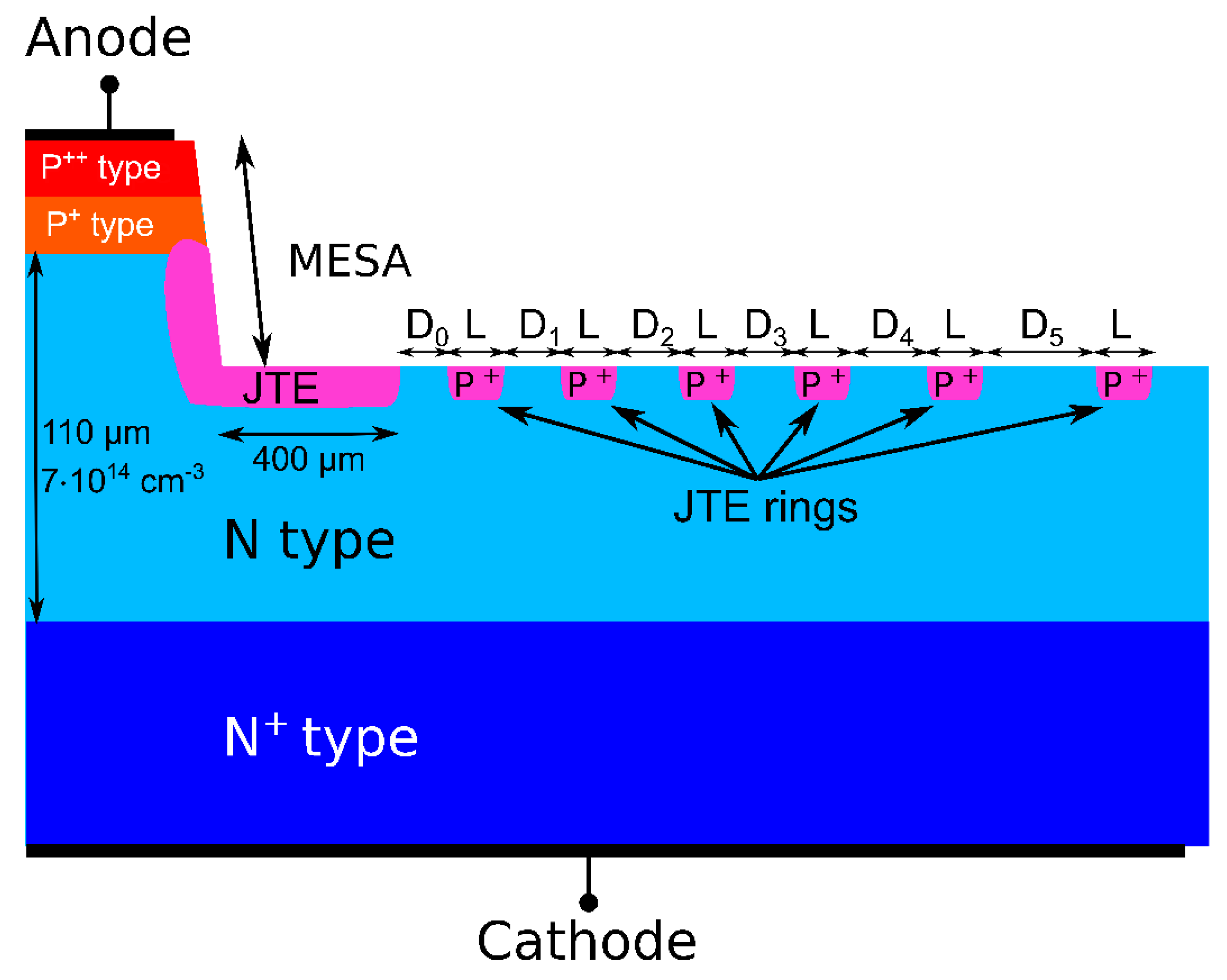
In order to sustain the high voltage, the junction termination has to be designed to spread the electric field that naturally occurs at the edge of the termination. A plethora of papers present in the literature report on techniques that fulfill this task with a relatively high efficiency (>80%) [16,17,18,19,20,21,22,23,24,25,26,27,28,29,30,31,32,33,34,35]. Another study on high-voltage bipolar diodes from SuperGrid has shown that an efficient peripheral protection is achieved by a mesa structure with a combination of junction termination extension (JTE) with JTE rings. In order to implement such a solution, the first step is to determine the JTE length. The efficiency of the peripheral protection has been evaluated through two dimensional (2D) TCAD simulations. As shown in Figure 1a, the edge termination efficiency has a strong dependence on the JTE dose. The efficiency is defined as the ratio between the breakdown voltage and the theoretical blocking voltage (13.2 kV). Increasing the JTE length above 400 µm does not improve further the breakdown voltage. For the sake of spatial optimization of the device (lowest material consumption), the optimal JTE length has been fixed to 400 µm and the computed JTE dose has been kept at 8.5 1012 cm−2. A smaller JTE length would result in a very small radius of curvature and produces a field crouding at the edges of the rectangular devices. Two-dimensional simulations do not take into account the radius of curvature and give a wrong impression on the JTE efficiency [28,36].
The next step is to compute the number of useful JTE rings. As shown in Figure 1b, the simulation of a JTE length of 400 µm with an increasing number of rings increases the efficiency of the peripheral protection. As a consequence, the JTE dose can be pushed further while the peripheral efficiency keeps increasing above 80%. Since the higher number of rings increases the dose tolerance, six rings were chosen with optimized width and increasing distance between them. Three-dimensional simulations could have been carried out to show the necessity of 400 µm JTE and six rings, but would require a long computing time [28].

3. Device Processing

Seven-level set masks have been designed to fabricate 10 kV–50 A silicon carbide bipolar diodes. Two sizes of diodes were fabricated. The active area was 59 mm2 for the bigger diodes and 9 mm2 for the smaller ones. The large diodes were optimized for the nominal current (50 A). This study focused on the large-size devices only.
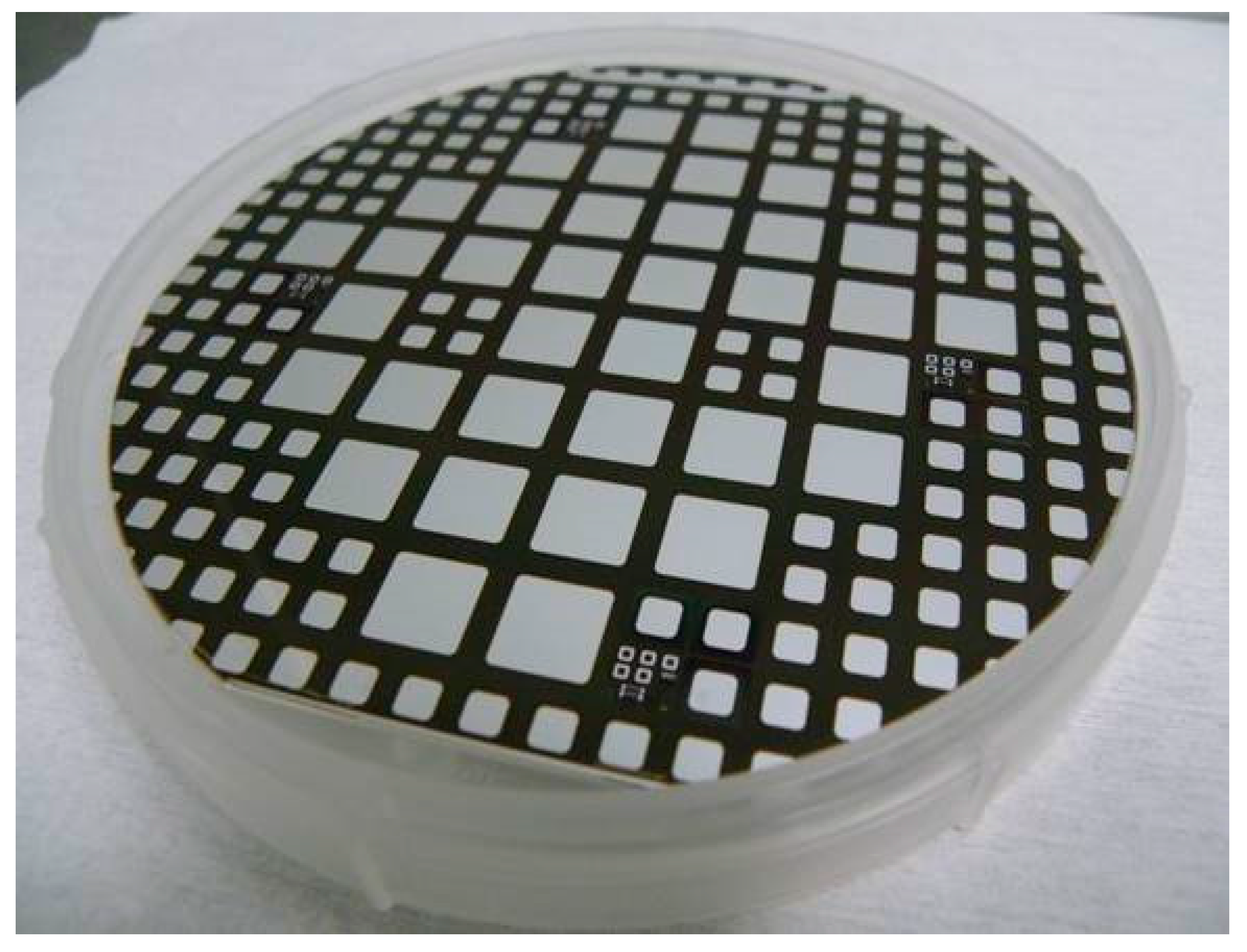
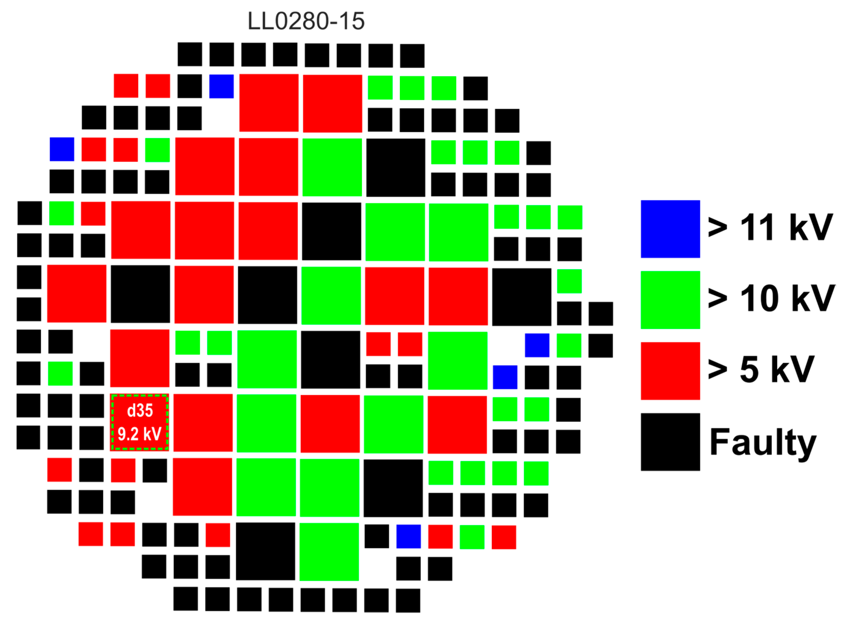
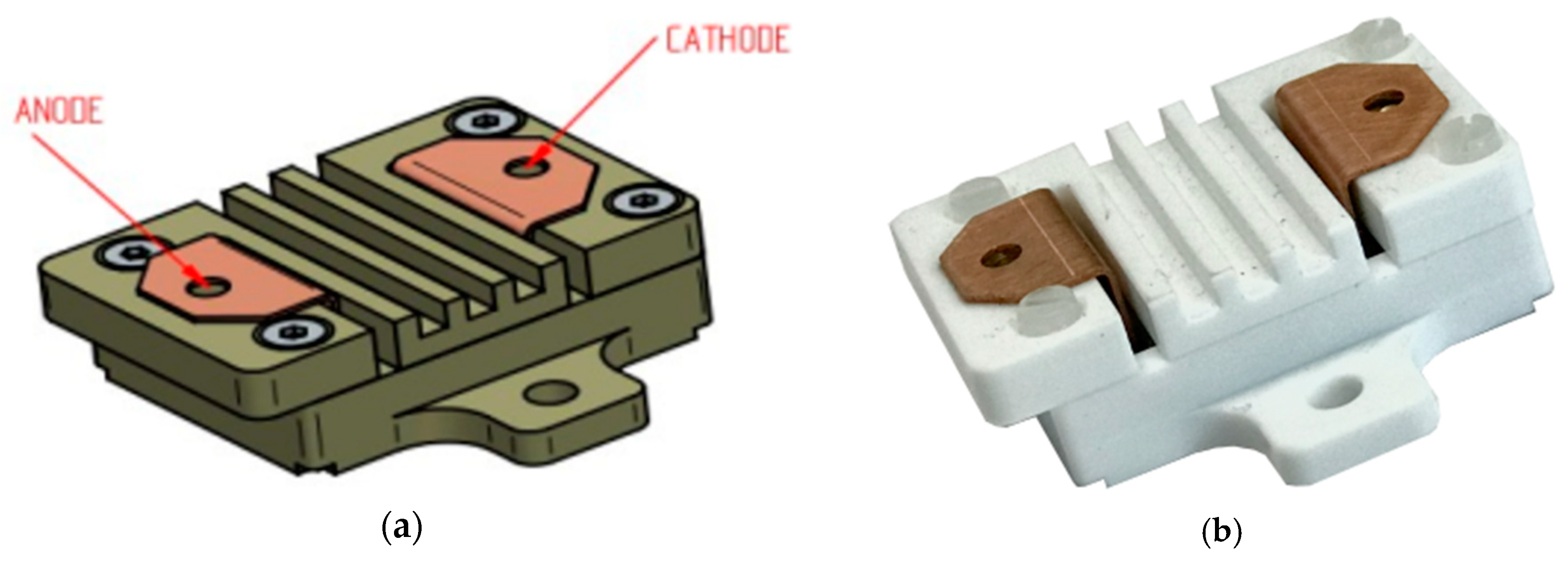
A cross-section of the device is shown in Figure 2. As described in the previous section, the edge termination of the PiN diodes is made of a mesa and 400 µm long junction termination extension (JTE) assisted by six JTE-rings with varying spacing between them (Di). The diode is square shaped with rounded edges. Each side has a length of 7.7 mm (0.6 cm2) and the radius of curvature of the corners fixed to 600 µm. The processed wafer, the breakdown voltage mapping and the packaging of the device are shown in Figure 3, Figure 4 and Figure 5, respectively.

4. Static and Dynamic Characterizations

Some devices have been packaged for high current and switching characterizations. Figure 6 shows the reverse-bias-static characterization results of large diodes. Static electrical characterizations were performed at SuperGrid Institute with a Keysight B1505A power device (B1505A, Keysight, Santa Rosa, CA, USA) analyzer equipped with a 10 kV module for high-voltage measurements and a Keysight B1506 (B1506, Keysight, Santa Rosa, CA, USA) (another power device analyzer) for repetitive measurements on components. Twelve large diode dies were packaged and measured as shown in Table 1. The packaged diodes were fixed on a hot plate and the specified temperature is the case temperature. To avoid any self-heating or temperature variation, pulsed-mode characterization was performed with 50 µs pulse duration. As can be seen in Table 1, forward voltage at 50 A (VF (50 A)) and 80 A (VF (80 A)), reverse leakage current at 1 kV (IR (1 kV)) and 3 kV (IR (3 kV)), the junction capacitance at 0 V (CJ (0 V)), 60 V (CJ (60 V)) and 3 kV (CJ (3 kV)) are in a tight distribution. This reveals the maturity of the fabrication process of the 10 kV SiC PiN diodes.

4.1. Forward Characteristics

Figure 6 shows the forward static characteristic for different temperatures. Standard behavior for a bipolar diode is observed with a voltage drop reduction (Figure 6a). The logarithmic scale clearly shows the reduction of the building potential at low current values (Figure 6b). At 10 A, a typical VF = 3.5 V and on-state resistance lower than 25 mΩ is obtained through a metallization process enhancement. The measured resistance is lower than the unipolar limit, proving that the device performs in high-injection operation mode and benefits from resistivity modulation.
Particularly, Figure 7 shows the decrease of the drop voltage at 80 A with increasing temperature. This is a well-known characteristic of bipolar devices. For low temperature, probably the serial resistance that increases with the temperature compensates the phenomenon.

4.2. Reverse Blocking Characteristics

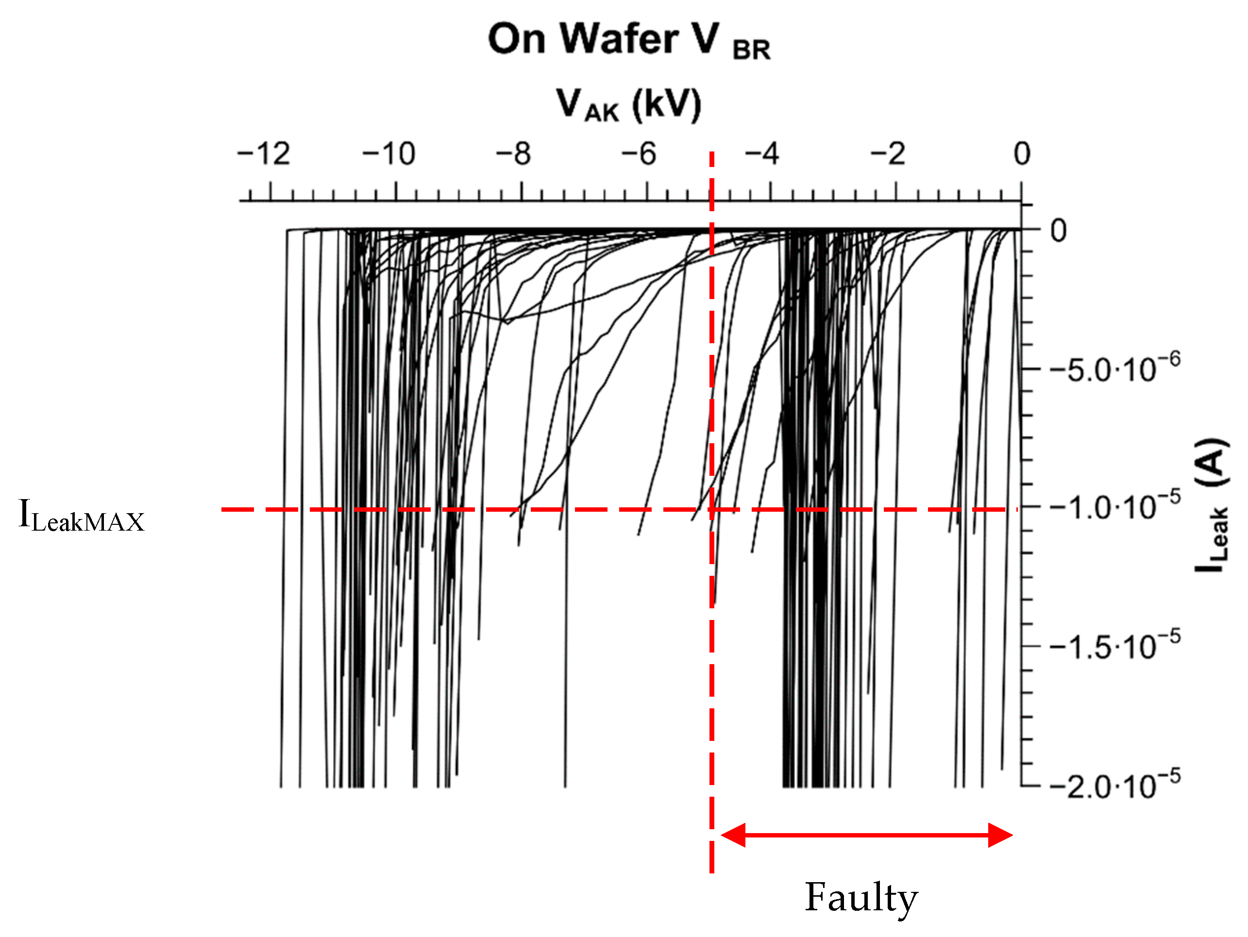
As shown in Figure 5, the breakdown voltage of the wafer LL0280-15 is very good with 38 diodes (big and small included) withstanding more than 10 kV and more than 60% of the wafer surface withstanding 5 kV. All the breakdown voltage curves are shown in Figure 8. The reason behind the breakdown voltage failure is related to the material quality, which is guaranteed at <5 defects/cm−2.
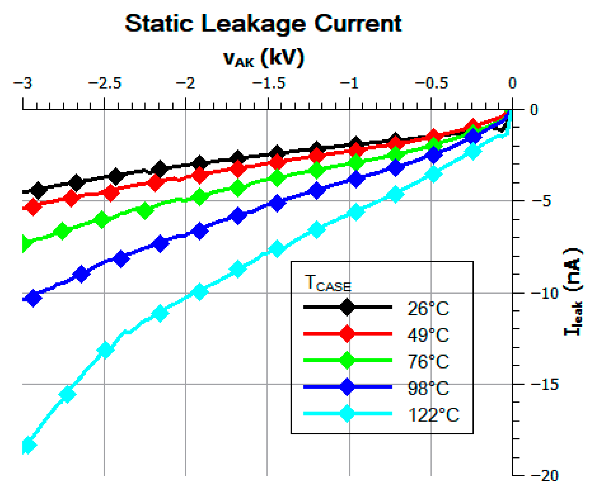
Concerning the reverse characteristic, Figure 9 shows the classical increase of the leakage current with the applied reverse voltage and the temperature.
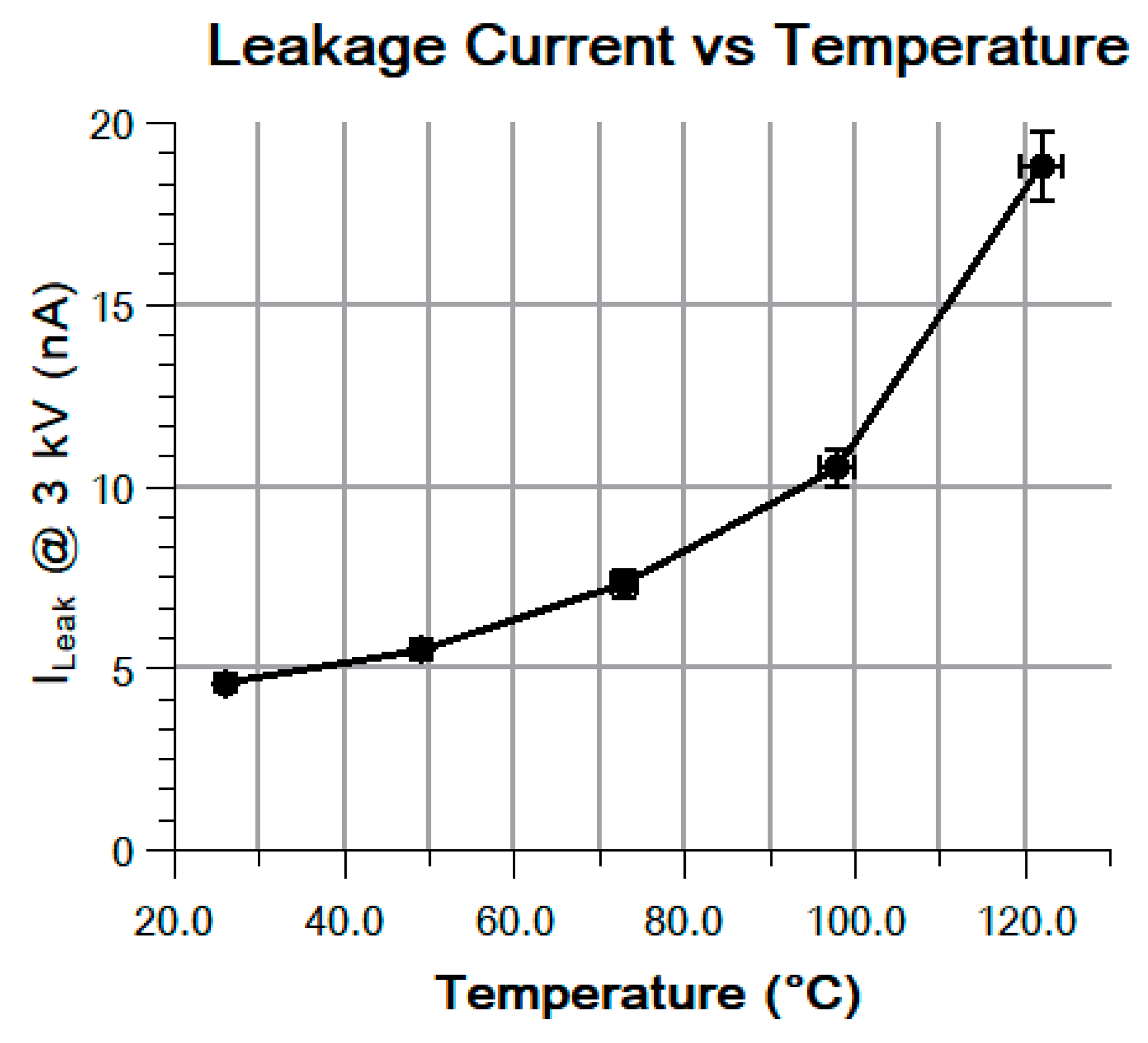
Particularly, Figure 10 shows the increase of the leakage current vs. the temperature at 3 kV. It shows a very small leakage current density, about one thousand times lower than equivalent silicon diodes or even SiC JBS diodes [37].

4.3. Junction Capacitance

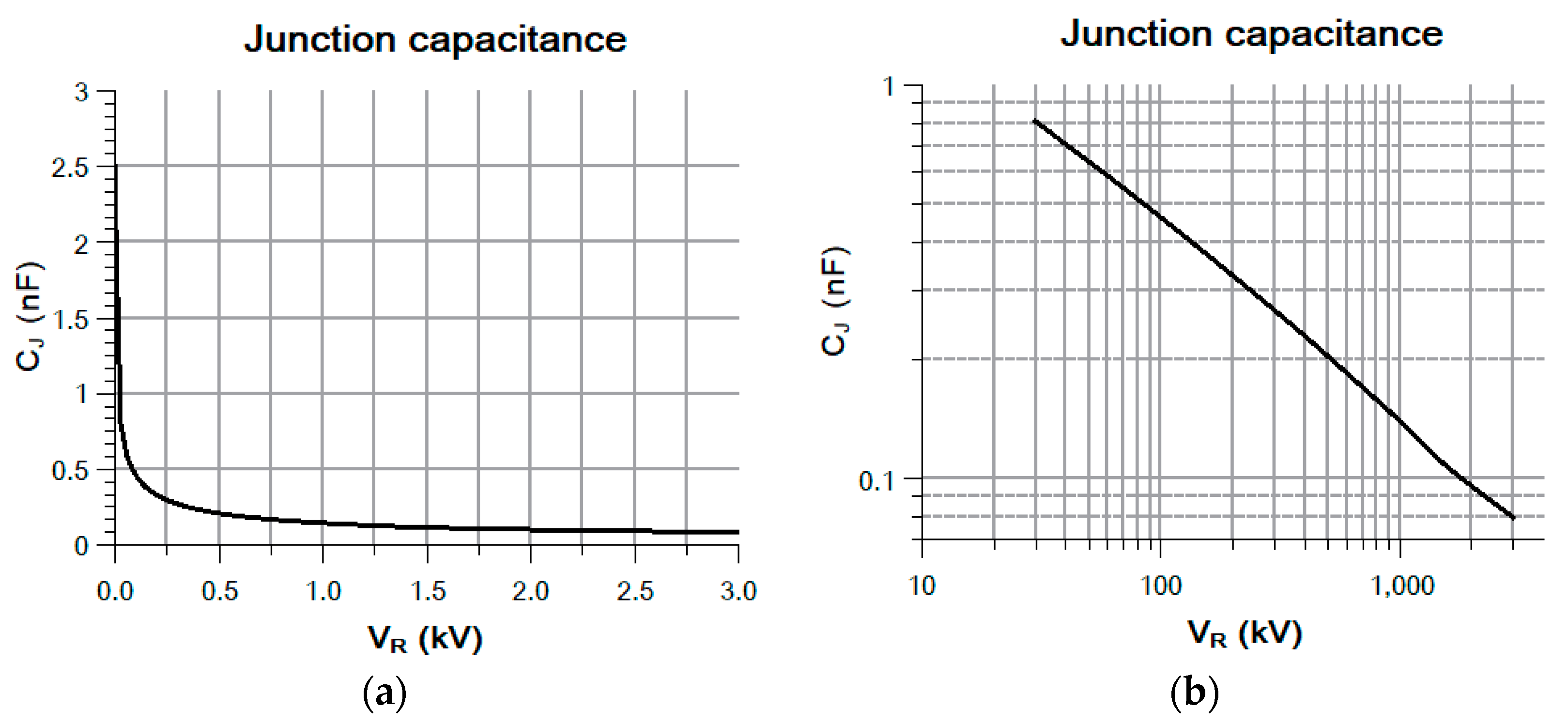
Figure 11a shows the junction capacitance with a very standard behavior for a bipolar junction. Moreover, Figure 11b shows the same curve in a log-log scale with an approximately constant slope of 0.52. The theoretical slope is 0.5 because the capacitance of a plane junction decreases with the square root of reverse voltage [38] (p. 87).

5. Switching Characteristics

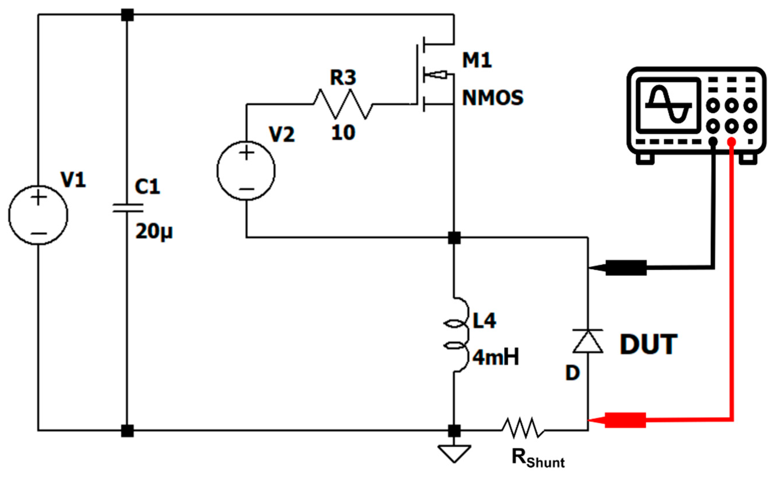
The switching performance of the manufactured devices was tested by means of clamped load inductive switching, commonly referred to as a double pulse test. The test circuit schematics are illustrated in Figure 12. All the parasitic elements were omitted even though they greatly degrade the operation of the device under test (DUT). The high-side MOSFET switch is made of a series association of six C2M0045170P 1.7 kV SiC MOSFETs. The unipolar nature of the switch renders it fast enough not to affect the switching performance of the freewheeling diode. No further details will be given on the switch as this paper focuses on the behavior of the 10 kV PiN diode only.
Measurements were carried out at room temperature on a DPO 5054B oscilloscope from Tektronix. A 25 mΩ current viewer resistor from T&M Research was placed in series with the PiN diode in order to accurately measure the current flowing through it. The signal was fed into the scope using a 50 Ω coaxial cable. The VKA voltage was measured with a high-voltage P6015A probe.
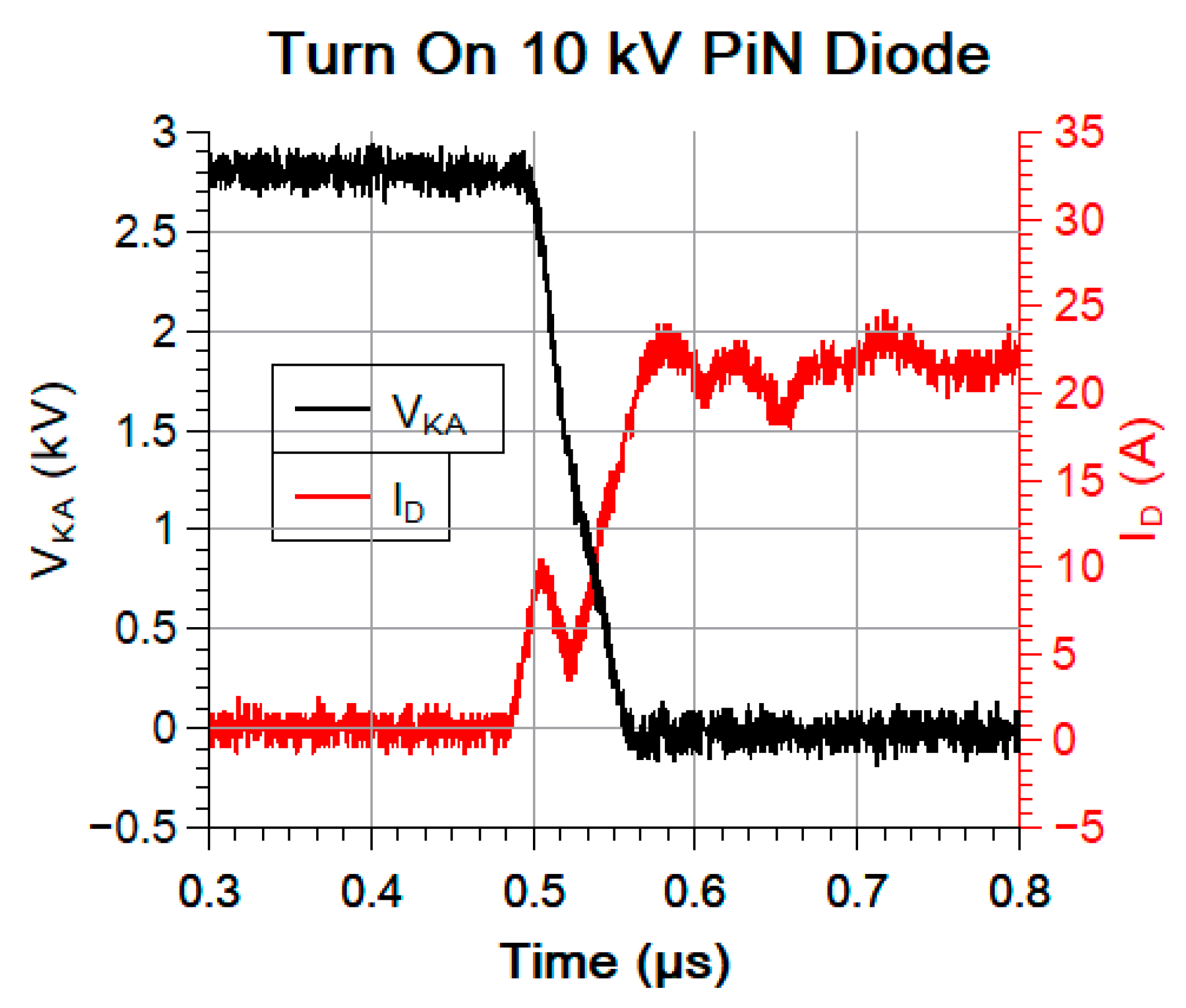
The recorded waveforms of the turn-on and turn-off behavior are shown in Figure 13 and Figure 14, respectively. The outstanding performance of the SiC PiN diode is plagued by the parasitic elements of the test circuit. Nevertheless, hard turn-on waveforms for a bus voltage of 2750 V and a current of 18.5 A show a very fast switching with low losses. The SiC PiN diode turns on in less than 100 ns for a di/dt = 311 A/µs and a dV/dt = −32 V/ns. The resulting turn-on energy is very low (EON = 0.53 mJ).
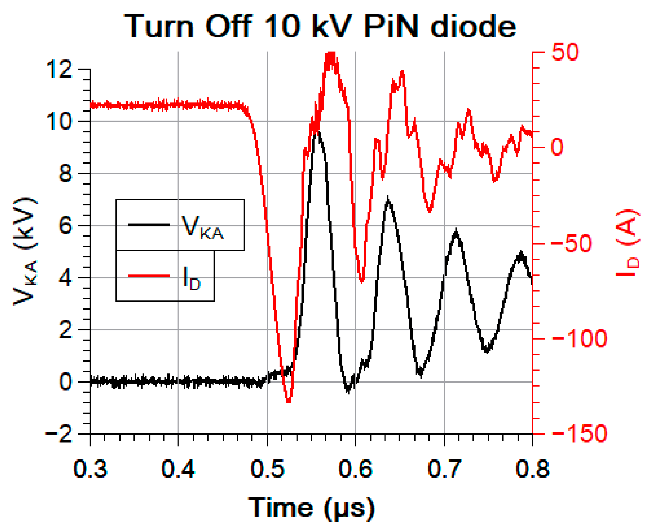
It is true that for turn-on operation there is room left for the bus voltage to be increased, but that would be too much risk to take since the most demanding conditions are met at a turn-off. As a matter of fact, due to parasitic inductances, an important overvoltage appears at a turn-off. As can be seen in Figure 14, the actual overvoltage is very important and almost undamped oscillations are observed. This is certainly due to the non-optimized layout of the test circuit because of the targeted 10 kV applied voltage. During these oscillations, the current in the diode becomes positive several times, which indicates a great contribution of the capacitive current. This situation can be very dangerous for the switch, as the high dV/dt and di/dt may induce EMC issues in the gate driver or/and high overvoltage on the switch side and lead to catastrophic failure. Nevertheless, the 10 kV SiC PiN diode handles the high dV/dt = 474 V/ns and high di/dt = −4.2 A/ns without apparent impact. Turn-off time can be estimated to less than 300 ns in these conditions. The turn-off energy is evaluated to EOFF = 6.1 mJ whereas the reverse recovery charge is calculated to be QRR = 4.1 µC. The current devices outrun the previous generation devices, both in terms of static and switching characteristics [39].

6. Conclusions

To the knowledge of the authors, this is the first time that high voltage and high current switching of a 10 kV 50 A SiC PiN device is reported. The switching performance of the device is proven to be outstanding, both from the static- and the dynamic/switching point of view. The design has been optimized and the fabrication has been matured. Static performance shows that the device makes use of the resistivity modulation from room temperature to 125 °C. Switching during the high-injection mode operation is carried out so fast that the parasitic elements of the test circuit become a limiting factor.
In the future, improvements to test circuit layout may allow for higher bus voltage and higher current operation of the device. Stress tests have to be carried out both in and out of the safe operating area (SOA) to assess the robustness and the reliability of the 10 kV PiN SiC diodes. Bipolar degradation tests have to be carried out.

Author Contributions

Conceptualization, D.P., H.M. and B.A.; TCAD simulation, L.V.P.; static and dynamic characterization, H.M.; switching tests, B.A.; coordination, D.P.

Funding

This work was supported by a grant overseen by the French National Research Agency (ANR) as part of the Investments for the Future programs (ANE-ITE-002-01).

Acknowledgments

The authors wish to acknowledge CALY Technologies for their help with the design and fabrication. Acknowledgments are addressed to DeepConcept also for their help with packaging.

Conflicts of Interest

The authors declare no conflict of interest. The funders had no role in the design of the study; in the collection, analyses or interpretation of data; in the writing of the manuscript, or in the decision to publish the results.

References

  1. Hull, B.A.; Sumakeris, J.J.; O’Loughlin, M.J.; Zhang, J.; Richmond, J.; Powell, A.R.; Paisley, M.J.; Tsvetkov, V.F.; Hefner, A.; Rivera, A. Development of Large Area (up to 1.5 cm2) 4H-SiC 10 kV Junction Barrier Schottky Rectifiers. Mater. Sci. Forum. 2009, 600–603, 931–934. [Google Scholar] [CrossRef]
  2. Kaji, N.; Niwa, H.; Suda, J.; Kimoto, T. Ultrahigh-voltage SiC p-i-n diodes with improved forward characteristics. IEEE Trans. Electron. Devices 2015, 62, 374–381. [Google Scholar] [CrossRef]
  3. Palmour, J.W.; Cheng, L.; Pala, V.; Brunt, E.V.; Lichtenwalner, D.J.; Wang, G.Y.; Richmond, J.; O’Loughlin, M.; Ryu, S.; Allen, S.T.; et al. Silicon carbide power MOSFETs: Breakthrough performance from 900 v up to 15 kV. In Proceedings of the International Symposium on Power Semiconductor Devices and ICs, Waikoloa, HI, USA, 15–19 June 2014; IEEE: Piscataway, NJ, USA, 2014; pp. 79–82. [Google Scholar] [CrossRef]
  4. Veliadis, V.; Stewart, E.J.; Hearne, H.; McNutt, T.; Chang, W.; Snook, M.; Lelis, A.J.; Scozzie, C. Design and Yield of 9 kV Unipolar Normally-ON Vertical-Channel SiC JFETs. Mater. Sci. Forum 2011, 679–680, 617–620. [Google Scholar] [CrossRef]
  5. Brunt, E.V.; Cheng, L.; O’Loughlin, M.J.; Richmond, J.; Pala, V.; Palmour, J. 27 kV, 20 A 4H-SiC n-IGBTs. Mater. Sci. Forum 2015, 821–823, 847–850. [Google Scholar] [CrossRef]
  6. Mojab, A.; Mazumder, S.K.; Cheng, L.; Agarwal, A.K.; Scozzie, C.J. 15-kV single-bias all-optical ETO thyristor. In Proceedings of the 2014 IEEE 26th International Symposium on Power Semiconductor Devices & IC’s (ISPSD), Waikoloa, HI, USA, 15–19 June 2014; IEEE: Piscataway, NJ, USA, 2014; pp. 313–316. [Google Scholar] [CrossRef]
  7. Marzoughi, A.; Romero, A.; Burgos, R.; Boroyevich, D. Comparing the State-of-the-Art SiC MOSFETs: Test results reveal characteristics of four major manufacturers? 900-V and 1.2-kV SiC devices. IEEE Power Electron. Mag. 2017, 4, 36–45. [Google Scholar] [CrossRef]
  8. Sundaresan, S.; Marripelly, M.; Arshavsky, S.; Singh, R. 15 kV SiC PiN diodes achieve 95% of avalanche limit and stable long-term operation. In Proceedings of the 2013 25th International Symposium on Power Semiconductor Devices & IC’s (ISPSD), Kanazawa, Japan, 26–30 May 2013; pp. 175–177. [Google Scholar] [CrossRef]
  9. Johannesson, D.; Nawaz, M.; Jacobs, K.; Norrga, S.; Nee, H.P. Potential of ultra-high voltage silicon carbide semiconductor devices. In Proceedings of the WiPDA 2016—4th IEEE Workshop on Wide Bandgap Power Devices and Applications, Fayetteville, AR, USA, 7–9 November 2016; pp. 253–258. [Google Scholar] [CrossRef]
  10. Yonezawa, Y.; Mizushima, T.; Takenaka, K.; Fujisawa, H.; Kato, T.; Harada, S.; Tanaka, Y.; Okamoto, M.; Sometani, M.; Okamoto, D.; et al. Low Vf and highly reliable 16 kV ultrahigh voltage SiC flip-type n-channel implantation and epitaxial IGBT. In Proceedings of the 2013 IEEE International Electron Devices Meeting, Washington, DC, USA, 9–11 December 2013; pp. 6.6.1–6.6.4. [Google Scholar] [CrossRef]
  11. Berthou, M.; Godignon, P.; Calvo, J.; Mihaila, A.; Bianda, E.; Nistor, I. Comparison of 5kV SiC JBS and PiN Diodes. Mater. Sci. Forum 2014, 778–780, 867–870. [Google Scholar] [CrossRef]
  12. Sentaurus TCAD simulation tool by Synopsis Inc. 2018. Available online: https://www.synopsys.com/content/dam/synopsys/silicon/datasheets/sentaurus_ds.pdf. (accessed on 29 November 2019).
  13. Konstantinov, A.O.; Wahab, Q.; Nordell, N.; Lindefelt, U. Ionization rates and critical fields in 4H silicon carbide. Appl. Phys. Lett. 1997, 71, 90–92. [Google Scholar] [CrossRef]
  14. Raynaud, C.; Tournier, D.; Morel, H.; Planson, D. Comparison of high voltage and high temperature performances of wide bandgap semiconductors for vertical power devices. Diam. Relat. Mater. 2010, 19, 1–6. [Google Scholar] [CrossRef]
  15. Planson, D.; Locatelli, M.; Lanois, F.; Chante, J. Design of a 600 V silicon carbide vertical power MOSFET. Mater. Sci. Eng. B 1999, 61–62, 497–501. [Google Scholar] [CrossRef]
  16. Pâques, G.; Dheilly, N.; Planson, D.; De Doncker, R.W.; Scharnholz, S. Graded Etched Junction Termination for SiC Thyristors. Mater. Sci. Forum 2011, 679–680, 457–460. [Google Scholar] [CrossRef]
  17. PEREZ, R. Optimisation of junction termination extension for the development of a 2000 V planar 4H-SiC diode. Diam. Relat. Mater. 2003, 12, 1231–1235. [Google Scholar] [CrossRef]
  18. Bolotnikov, A.V.; Muzykov, P.G.; Zhang, Q.; Agarwal, A.K.; Sudarshan, T.S. Junction termination extension implementing drive-in diffusion of boron for high-voltage SiC devices. IEEE Trans. Electron. Devices 2010, 57, 1930–1935. [Google Scholar] [CrossRef]
  19. Perez, R.; Tournier, D.; Perez-Tomas, A.; Godignon, P.; Mestres, N.; Millan, J. Planar Edge Termination Design and Technology Considerations for 1.7-kV 4H-SiC PiN Diodes. IEEE Trans. Electron. Devices 2005, 52, 2309–2316. [Google Scholar] [CrossRef]
  20. Sung, W.; Baliga, B.J. A Near Ideal Edge Termination Technique for 4500V 4H-SiC Devices: The Hybrid Junction Termination Extension. IEEE Electron. Device Lett. 2016, 37, 1609–1612. [Google Scholar] [CrossRef]
  21. Sung, W.; Huang, A.Q.; Baliga, B.J. Bevel Junction Termination Extension—A New Edge Termination Technique for 4H-SiC High-Voltage Devices. IEEE Electron. Device Lett. 2015, 36, 594–596. [Google Scholar] [CrossRef]
  22. Li, X.Q.; Tone, K.; Cao, L.H.; Alexandrov, P.; Fursin, L.; Zhao, J.H. Theoretical and Experimental Study of 4H-SiC Junction Edge Termination. Mater. Sci. Forum 2000, 338–342, 1375–1378. [Google Scholar] [CrossRef]
  23. Li, X.; Tone, K.; Fursin, L.; Zhao, J.H.; Burke, T.; Alexandrov, P.; Pan, M.; Weiner, M. Multistep junction termination extension for SiC power devices. Electron. Lett. 2001, 37, 392. [Google Scholar] [CrossRef]
  24. Sheridan, D.C.; Niu, G.; Cressler, J.D. Design of single and multiple zone junction termination extension structures for SiC power devices. Solid State Electron. 2001, 45, 1659–1664. [Google Scholar] [CrossRef]
  25. Ghandi, R.; Buono, B.; Domeij, M.; Malm, G.; Zetterling, C.-M.; Ostling, M. High-Voltage 4H-SiC PiN Diodes With Etched Junction Termination Extension. IEEE Electron. Device Lett. 2009, 30, 1170–1172. [Google Scholar] [CrossRef]
  26. Sung, W.; Van Brunt, E.; Baliga, B.J.; Huang, A.Q. A New Edge Termination Technique for High-Voltage Devices in 4H-SiC–Multiple-Floating-Zone Junction Termination Extension. IEEE Electron. Device Lett. 2011, 32, 880–882. [Google Scholar] [CrossRef]
  27. Niwa, H.; Suda, J.; Kimoto, T. 21.7 kV 4H-SiC PiN Diode with a Space-Modulated Junction Termination Extension. Appl. Phys. Express 2012, 5. [Google Scholar] [CrossRef]
  28. Phung, L.V.; Planson, D.; Brosselard, P.; Tournier, D.; Brylinski, C. 3D TCAD Simulations for More Efficient SiC Power Devices Design. ECS Trans. 2013, 58, 331–339. [Google Scholar] [CrossRef]
  29. Brosselard, P.; Planson, D.; Scharnholz, S.; Raynaud, C.; Zorngiebel, V.; Lazar, M.; Chante, J.-P.; Spahn, E. Edge termination strategies for a 4kV 4H–SiC thyristor. Solid State Electron. 2006, 50, 1183–1188. [Google Scholar] [CrossRef]
  30. Mahajan, A.; Skromme, B.J. Design and optimization of junction termination extension (JTE) for 4H–SiC high voltage Schottky diodes. Solid State Electron. 2005, 49, 945–955. [Google Scholar] [CrossRef]
  31. Feng, G.; Suda, J.; Kimoto, T. Space-Modulated Junction Termination Extension for Ultrahigh-Voltage p-i-n Diodes in 4H-SiC. IEEE Trans. Electron. Devices 2012, 59, 414–418. [Google Scholar] [CrossRef]
  32. Paques, G.; Scharnholz, S.; Dheilly, N.; Planson, D.; De Doncker, R.W. High-Voltage 4H-SiC Thyristors With a Graded Etched Junction Termination Extension. IEEE Electron. Device Lett. 2011, 32, 1421–1423. [Google Scholar] [CrossRef]
  33. Thion, F.; Isoird, K.; Planson, D.; Locatelli, M.-L.; Ding, H. Simulation and design of junction termination structures for diamond Schottky diodes. Diam. Relat. Mater. 2011, 20, 729–732. [Google Scholar] [CrossRef] [Green Version]
  34. Nguyen, T.T.H.; Lazar, M.; Augé, J.L.; Morel, H.; Phung, L.V.; Planson, D. Vertical Termination Filled with Adequate Dielectric for SiC Devices in HVDC Applications. Mater. Sci. Forum 2016, 858, 982–985. [Google Scholar] [CrossRef] [Green Version]
  35. Bolotnikov, A.; Losee, P.; Deeb, P.; Wang, M.; Dunne, G.; Kretchmer, J.; Arthur, S.; Stevanovic, L. Design of area-efficient, robust and reliable junction termination extension in SiC devices. Mater. Sci. Forum 2016, 858, 737–740. [Google Scholar] [CrossRef]
  36. Nguyen, D.M.; Huang, R.; Phung, L.V.; Planson, D.; Berthou, M.; Godignon, P.; Vergne, B.; Brosselard, P. Edge Termination Design Improvements for 10 kV 4H-SiC Bipolar Diodes. Mater. Sci. Forum 2013, 740–742, 609–612. [Google Scholar] [CrossRef]
  37. Hull, B.A.; Sumakeris, J.J.; O’Loughlin, M.J.; Zhang, Q.; Richmond, J.; Powell, A.R.; Imhoff, E.A.; Hobart, K.D.; Rivera-Lopez, A.; Hefner, A.R. Performance and Stability of Large-Area 4H-SiC 10-kV Junction Barrier Schottky Rectifiers. IEEE Trans. Electron. Devices 2008, 55, 1864–1870. [Google Scholar] [CrossRef]
  38. Sze, S.M.; Ng, K.K. Physics of Semiconductor Devices; John Wiley & Sons, Inc.: Hoboken, NJ, USA, 2006; Volume 2006, ISBN 9780470068328. [Google Scholar] [CrossRef] [Green Version]
  39. Asllani, B.; Planson, D.; Bevilacqua, P.; Fonder, J.B.; Choucoutou, B.; Morel, H.; Phung, L.V. Advanced Electrical Characterisation of High Voltage 4H-SiC PiN Diodes. Mater. Sci. Forum 2019, 963, 567–571. [Google Scholar] [CrossRef] [Green Version]
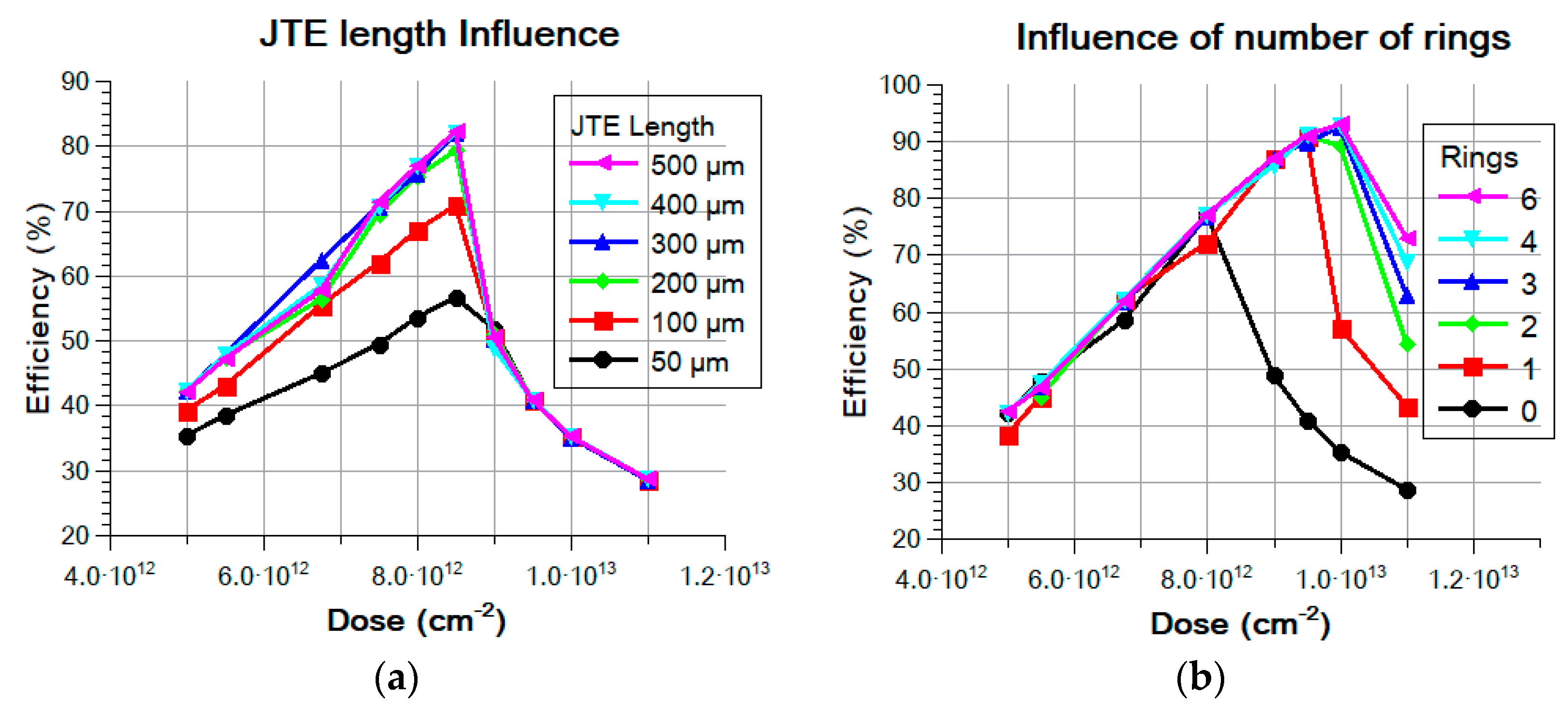
Figure 1. Simulated results showing the efficiency of the JTE dose for different JTE length (a) and the efficiency of the JTE dose for a different number of rings with a 400 µm JTE length (b). The mesa depth is 2.5 µm for both cases.
Energies 12 04566 g001
Figure 2. Schematic cross-section of the fabricated PiN diode with its high-voltage peripheral protection. Di is the spacing between rings and L is the length of the ring.
Energies 12 04566 g002
Figure 3. Example of realized PiN diodes on a 4” SiC wafer with 50 A–10 kV bipolar diodes.
Energies 12 04566 g003
Figure 4. Breakdown voltage mapping of the wafer LL0280-15. Some devices withstand more than 11 kV and more than 60% (>5 kV) of the wafer surface yields exploitable devices. Device d35 is shown in dashed square.
Energies 12 04566 g004
Figure 5. 3D rendering (a) and the packaged device (b) after processing and wafer dicing.
Energies 12 04566 g005
Figure 6. Forward characteristics of a packaged diode (d35) for different ambient temperatures: (a) linear scale and (b) semi-logarithmic scale.
Energies 12 04566 g006
Figure 7. Voltage drop at 80 A versus the temperature (Device d35).
Energies 12 04566 g007
Figure 8. Leakage current vs. the applied voltage for all the devices on wafer LL0280-15. The dashed line defines the breakdown voltage.
Energies 12 04566 g008
Figure 9. Leakage current vs. the applied voltage for different temperatures (Device d35).
Energies 12 04566 g009
Figure 10. Leakage current vs. the temperature at 3 kV (Device d35).
Energies 12 04566 g010
Figure 11. Junction capacitance vs. the reverse applied voltage at 26 °C (Device d35). Linear scale and log-log scale are shown on (a) and on (b) respectively.
Energies 12 04566 g011
Figure 12. Clamped load inductive switching circuit schematic without the parasitic elements.
Energies 12 04566 g012
Figure 13. Room temperature turn-on of the PiN diode happens faster than 100 ns with very low energy loss. Turn-on energy is only 0.53 mJ for a bus voltage of 2750 V at 18.5 A (Device d35).
Energies 12 04566 g013
Figure 14. Room temperature turn-off of the PiN diode happens faster than 200 ns with low energy loss. Turn-on energy is only 6.1 mJ for a bus voltage of 2750 V at 21 A (Device d35).
Energies 12 04566 g014
Table 1. Statistics on twelve characterized devices.
Device FeatureVF (50 A)VF (80 A)IR (1 kV)IR (3 kV)CJ (0 V)CJ (60 V)CJ (3 kV)
unitVVnAnApFpFpF
average4.985.6815.2193.2255759482.2
min4.595.191.994.57248056779.1
max5.366.2232.7359264062285.1
σ0.200.299.79137.1250.3017.072.44