Article

A Novel Hybrid Converter Proposed for Multi-MW Wind Generator for Offshore Applications

1
Key Laboratory of Control of Power Transmission and Conversion (Ministry of Education), Shanghai Jiao Tong University, Shanghai 200240, China
2
Department of Electrical Engineering, School of Electronic Information and Electrical Engineering Shanghai Jiao Tong University, Shanghai 200240, China
*
Author to whom correspondence should be addressed.
Energies 2019, 12(21), 4167; https://doi.org/10.3390/en12214167
Submission received: 6 October 2019 / Revised: 22 October 2019 / Accepted: 24 October 2019 / Published: 1 November 2019
(This article belongs to the Special Issue Power Electronics Applications in Renewable Energy Systems)

Abstract

:
Modern multi-MW wind generators have used multi-level converter structures as well as parallel configuration of a back to back three-level neutral point clamped (3L-NPC) converters to reduce the voltage and current stress on the semiconductor devices. These configurations of converters for offshore wind energy conversion applications results in high cost, low power density, and complex control circuitry. Moreover, a large number of power devices being used by former topologies results in an expensive and inefficient system. In this paper, a novel bi-directional three-phase hybrid converter that is based on a parallel combination of 3L-NPC and ‘n’ number of Vienna rectifiers have been proposed for multi-MW offshore wind generator applications. In this novel configuration, total power equally distributes by sharing of total reference current in each parallel-connected generator side power converter, which ensures the lower current stress on the semiconductor devices. Newly proposed topology has less number of power devices compared to the conventional configuration of parallel 3L-NPC converters, which results in cost-effective, compact in size, simple control circuitry, and good performance of the system. Three-phase electric grid is considered as a generator source for implementation of a proposed converter. The control scheme for a directly connected three-phase source with a novel configuration of a hybrid converter has been applied to ratify the equal power distribution in each parallel-connected module with good power factor and low current distortion. A parallel combination of a 3L-NPC and 3L-Vienna rectifier with a three-phase electric grid source has been simulated while using MATLAB and then implemented it on hardware. The simulation and experimental results ratify the performance and effectiveness of the proposed system.

1. Introduction

From the last few decades, power sectors are considering accommodating clean and sustainable energy sources to minimize the adverse effect of non-sustainable energy. Among the sustainable energy sources, wind energy has become a globally more attractive solution for high power electricity production [1]. According to a report, the State of Alaska Legislature has committed to supplying 50% of its energy from renewable sources by 2025 [2]. Meanwhile, China has also set her target to rise supply from renewable energy up to 20% in the national energy consumption by 2030 [3]. Therefore, with the passage of time, the demand for high power generator in manufacturing and installing industries is also growing for high power production.
Wind energy conversion systems (WECSs) have been installed in 80 countries and their total expected capacity will reached 800 GW by 2021 [4,5]. Nowadays, the most commonly deployed high capacity wind energy conversion systems occurs in the form of onshore and offshore wind farms. Such a developing tendency in wind energy area attracts the manufacturing companies to build individual high power wind turbine generator. Therefore, from the last few years’, generator designing industries are manufacturing high power generators up to 10 MW, which will become double after few years [6,7].
For the wind energy conversion system, a power electronics converter plays an important role as a machine side frond-end converter [8,9]. Generated alternating energy from the wind needs to be converted into stable direct current for appropriate use in numerous applications, such as standalone and grid-connected systems [10,11]. Therefore, generator side converters are considered the most accountable part for efficiency, power density, control circuitry, and cost of the entire wind energy conversion system.
Among power electronics converters, there are various sorts of rectifiers that have used for generator side energy conversion, such as, passive, active, and hybrid rectifier, as reviewed in [12,13]. Among the family of passive rectifiers, diode full-bridge rectifier remained more common in the past as a front end rectifier with harmonics and power factor problems, but these issues lower the efficiency of the whole system. Therefore, to overcome the aforementioned problems, another two-level six switch active rectifier, as shown in Figure 1a, became more popular as a front end rectifier whereas both discussed types of rectifiers were best designed for low power applications up to KVs [13]. Thus, for medium or high power applications, multilevel converter as well as parallel configuration of neutral point clamped (NPC) converter, as shown in Figure 1b, became more attractive in wind energy conversion systems (WECSs) to reduce the voltage and current stress on the semiconductor devices [14,15,16].
Nowadays, a three-level NPC converter as a front end rectifier is commonly used with a few hundreds of KW wind generator. While, in multi-MW wind generator, parallel arrangement of 3L-NPC converters, as shown in Figure 2, became a more attractive solution for reducing the current stress on power devices by equal sharing of total current in all parallel-connected converters. Otherwise, high rated semiconductor devices would be required that can bear thousands of amperes and KVolt, which are expensive and not common in markets. Besides, the parallel configuration of NPC converters also increases the complexity in aspects of a large number of active switches and control circuitry, which affects cost and efficiency. Therefore, another type of active rectifier, known as the Vienna rectifier analogous to a t-type inverter, as shown in Figure 1c, has been considered as a generator side unidirectional rectifier that is based on numerous advantages, as mentioned in [17].
In the aspects of power flow direction, NPC has bi-directional, whereas the Vienna rectifier has unidirectional power flow options. In the case of wind energy integration with the electric grid, occasionally voltage sag occurs because of rapid change in rotor speed, which demands stabilizing power operation. In addition, it also sometimes requires a little power for field excitation of the wind generator. Accordingly, a full-scale bi-directional power flow converter helps to deal with such problems [18,19,20,21].
A new bi-directional configuration of converter has been proposed for high power offshore WEC applications by keeping in view the above-mentioned issues for bidirectional power flow in multi-MW WECS. In this fresh topology, a single module of three-phase/three-level NPC converter connected in parallel with ‘n’ number of three-phase Vienna rectifiers has been designed. In this configuration of converters, NPC works as a bi-directional power flow, while Vienna rectifiers work as a unidirectional active-rectifier having a lower number of active switches and lower cost as compared to 3L-NPC [22]. The functioning of a deliberated parallel-connected converters ratifies for a higher range of wind generator applications by dropping current stress on power devices in each parallel converters [23,24]. Hence, the overall proposed hybrid configuration uses less number of switches with high power density as compared to existing parallel-connected three-level neutral point clamped converters. The major advantages of the considered system and its control scheme are:
  • reduction of switching loss;
  • reduction in number of switches;
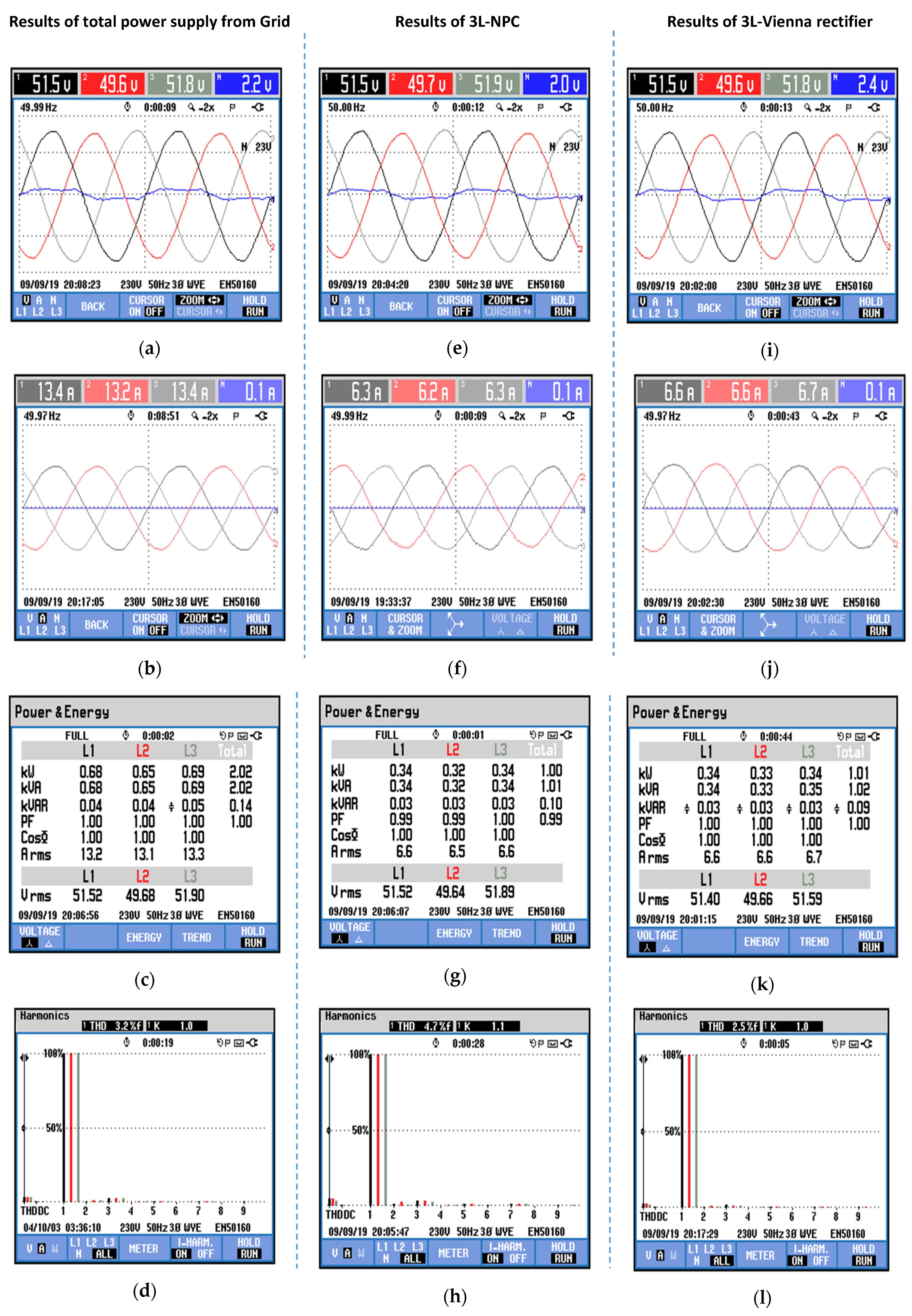
  • works with unity PF and less THD;
  • cost-effective bi-directional converter;
  • reduction of current rating power devices; and,
  • improved the converter handling power capacity up to multi-MW.
Different configurations of machine side converters for wind energy transformation are discussed in Section 2; the proposed bi-directional hybrid converter scheme is presented in Section 3; the control scheme and working of the proposed system are discussed in Section 4; and, the MATLAB based simulation results of suggested hybrid converter are shown in Section 5. In Section 6, the DSP based experimental results are presented. Finally, in Section 7, the conclusion is discussed.

2. Front End Active Rectifiers for WECS

In this section, the most commonly used active rectifiers and number of devices used by them have been studied. Due to the inefficient and low power applications of passive rectifiers, they are not considered as a good option in WEC applications.
Therefore, active rectifiers that are based on control switches became more captivating for efficient energy conversion in WECSs [13,25]. Among the family of active rectifiers, the two-level converter was most commonly used as a front end rectifier in energy conversion progression. On the other hand, such a low power application rectifier has higher harmonics and EMI. Although, in the case of medium or high power wind generators up to 10 MW or more, it cannot endure the voltage and current stress, because of the low power handling capability of the power devices [15,24]. Hence, predefined multilevel or parallel configuration of converters was considered as a vigorous solution, as discussed in Section 1, to overcome these issues. From the last few years, a three-level back-to-back neutral point diode clamped (NPC) converters are extensively using as a front end rectifier as a machine side converter. This type of dual-mode converter can work as an inverter as well as a rectifier mode, which mainly depends on its modulation signal. Additionally, a three-level NPC converter or its parallel configuration also handle more power with low power handling devices [26,27,28,29].
The rest of NPC circuit, there is another three-level unidirectional rectifier having less number of active switches and easy to implement as a machine side rectifier that is called a Vienna rectifier. It also has a boosting and continuous input current ability. According to the efficiency point of view, a comparative analysis of all three topologies of Vienna rectifier has been discussed in [30], which shows that three-phase Vienna with a t-type inverter shape with six control switches, as shown in Figure 1c, has more efficiency than all other topologies. This simplest three-phase power circuit shows less number of power switches, easy to control, and cost-effective circuit. It has several advantages, such as high efficiency, operation at high power factor, and being reliable to implement with high power density [22,30].
Table 1 mentions the number of devices used by all discussed circuits.
Based on a comparative study of devices used by discussed converters, as mentioned in Table 1 and aforementioned problems of converters, two parallel combinations of 3L-NPC converters use almost twice the number of power devices as compared to two parallel-connected Vienna rectifiers. Therefore, a parallel configuration of two 3L-NPC will make the circuit complex, expensive, and with low power density. Thus, a new hybrid bi-directional converter for high power applications with high power density and cost-effective is recommended, as shown in the next section.

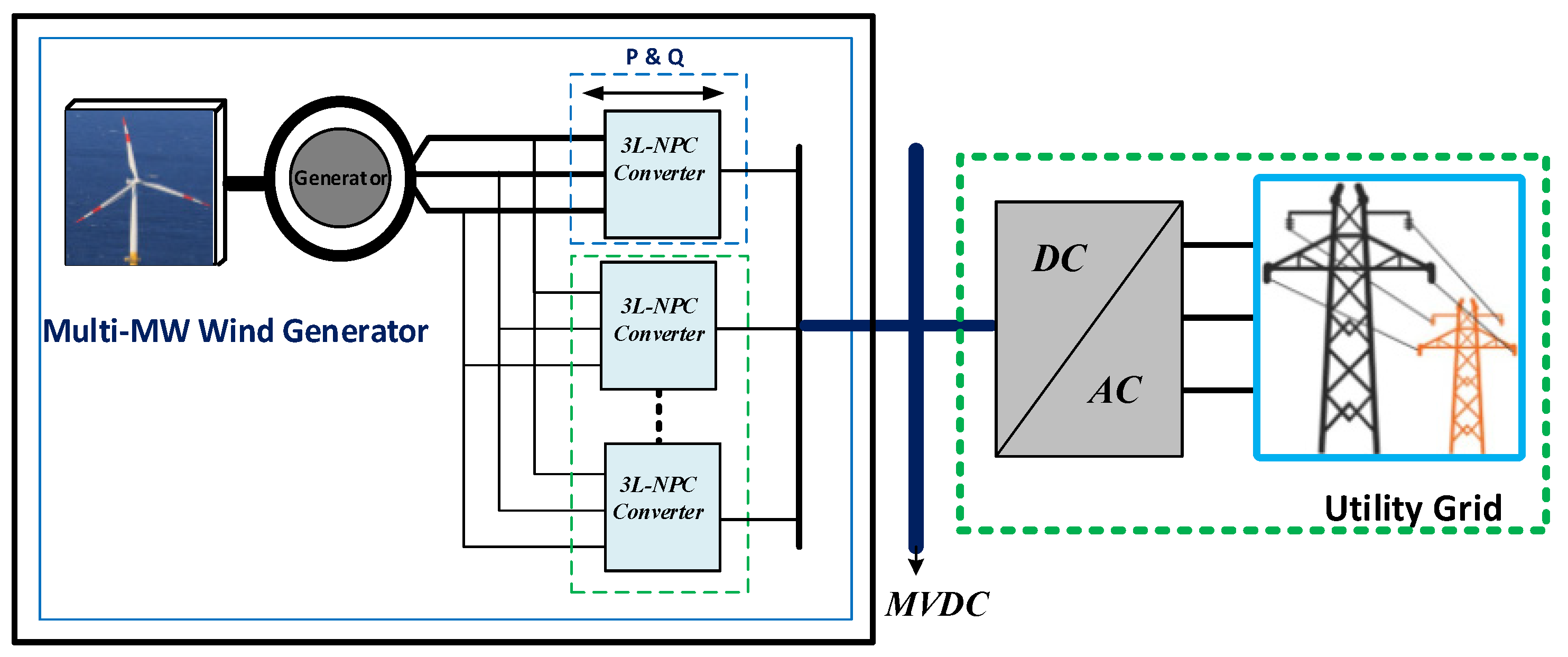
3. Proposed Converter Configuration

Figure 3 shows a new hybrid converter directly connected with multi-MW wind generator. In this arrangement, 3L-NPC works as a bi-directional converter for motoring as well as generating action, intended for electrically field excitation to produce starting torque. In the case of electrical field excitation in the generator, 3L-NPC works as an inverter mode, on the other hand, it works as a rectifier mode, just like all interleaved unidirectional Vienna rectifiers operation, as mentioned in the proposed scheme. Out of (n + 1) parallel-connected power converters, the projected system only uses a single unit of three-phase 3L-NPC converter and ‘n’ number of Vienna rectifiers, as shown in Figure 3. A deliberated system, in fact, is a parallel operation of circuits, as mentioned in Figure 2b,c, which results in low THD and good power factor. The total power equally distributes in each power electronics building block of the deliberated system by 1/(n + 1), which helps to select the lower power rating semiconductor devices. Hence, the intended power converter interface best fit for multi-MW generators. A recommended bidirectional power flow system is specially designed for high power wind generators, which are often used as directly connected offshore wind turbines in wind energy conversion solicitations [22,31].

Parallel Operation of Converters

A balanced three-phase electric grid has been considered as a generated supply for the validation of the proposed converter operation. Mathematical form of voltages in a three-phase system can be written as:
U g a = E S i n ( w t )
U g b = E S i n ( w t 120 )
U g c = E S i n ( w t + 120 )  
where Uga, Ugb, and Ugc are the phase voltages of the deliberated electric grid, while ‘E’ and ‘w’ represent the peak voltage and angular frequency of the input source.
In the proposed configuration, NPC works as a full-scale converter for the considered three-phase power feedback system, while others interleaved Vienna rectifiers work as a unidirectional power flow from generator to the DC link. In the planned system, the total output power of the generator divided by a factor of 1/(n + 1) for each converter. Where ‘1’ in the denominator represent to the NPC, while ‘n’ represent the number of other parallel connected Vienna rectifiers.
The uppermost NPC converter, as depicted in Figure 3, have dual nature of operation (rectifier & inverter) while all other parallel-connected circuits only work as a unidirectional rectifier mode of operation. Phase voltages of NPC converter as a rectifier mode are mentioned in Table 2 while assuming ideal power switches with their following switching states:
d x = { 1   S x 1 + ,   S x 2 +   : O N S x 1 ,   S x 2 : O F F 0   S x 1 ,   S x 2 +   : O N S x 1 + ,   S x 2 : O F F 1   S x 1 ,   S x 2   : O N S x 1 + ,   S x 2 + : O F F
Whereas, x = a, b, c for three-phase system. There are three kinds of switching states for a single leg 3L-NPC. Therefore, overall states for three-phase converter are ‘33 =27’, which can be expressed as:
U g x 0 = { V 1   i f d x = 1 0 i f d x = 0 V 2 i f d x = 1
Moreover, for ‘n’ number of parallel-connected unidirectional Vienna rectifiers, the most efficient topology, like t-type inverter with six active switches, has been used. Assuming the balanced grid supply voltage at the input of three-phase Vienna rectifier the terminal voltages with switching states and polarity of the phase current can be expressed as:
U g A 0 = V d c 2 s g n ( i s a 2 n ) ( 1 S a )
    U g B 0 = V d c 2 s g n ( i s b 2 n ) ( 1 S b )    
    U g C 0 = V d c 2 s g n ( i s c 2 n ) ( 1 S c )    
where S a , S b , and S c are the switching states that switched between 1 and 0. Table 3 mentions eight different switching conditions [32,33,34].
Vienna rectifiers have boosting ability with the inductive filter at the input side of the circuit, which can be calculated while using Equation (5) [35].
L i = V bus 8 F s w Δ I p p   max  
where Li is the input inductor, Vbus is a dc bus voltage, FSW is the value of switching frequency, and ∆Ippmax is a maximum ripple current value.
Finally, the output of the rectifier terminals has connected with the common dc-link capacitors to obtain the regulated suppressed ripple content and for power flow control problems. The dc-link consists of two equally sized capacitors that were also used to provide a low inductive path for the turned-off current. The dc-link capacitance can be calculated by Equation (6).
C D C = 2 τ S N V D C 2  
where S N is a nominal apparent power of the converter, τ is the time constant that usually considered as less than 5 ms, and V D C is the total dc-link voltage [36]. Equation (7) determines the individual capacitor sizes.
1 C D C = 1 C D C 1 + 1 C D C 2
having the same magnitude of current. Moreover, the dc-link voltage is to be kept constant for the input variations due to wind or load side dynamics. The overall control strategy of the proposed structure is demonstrated in the next section.

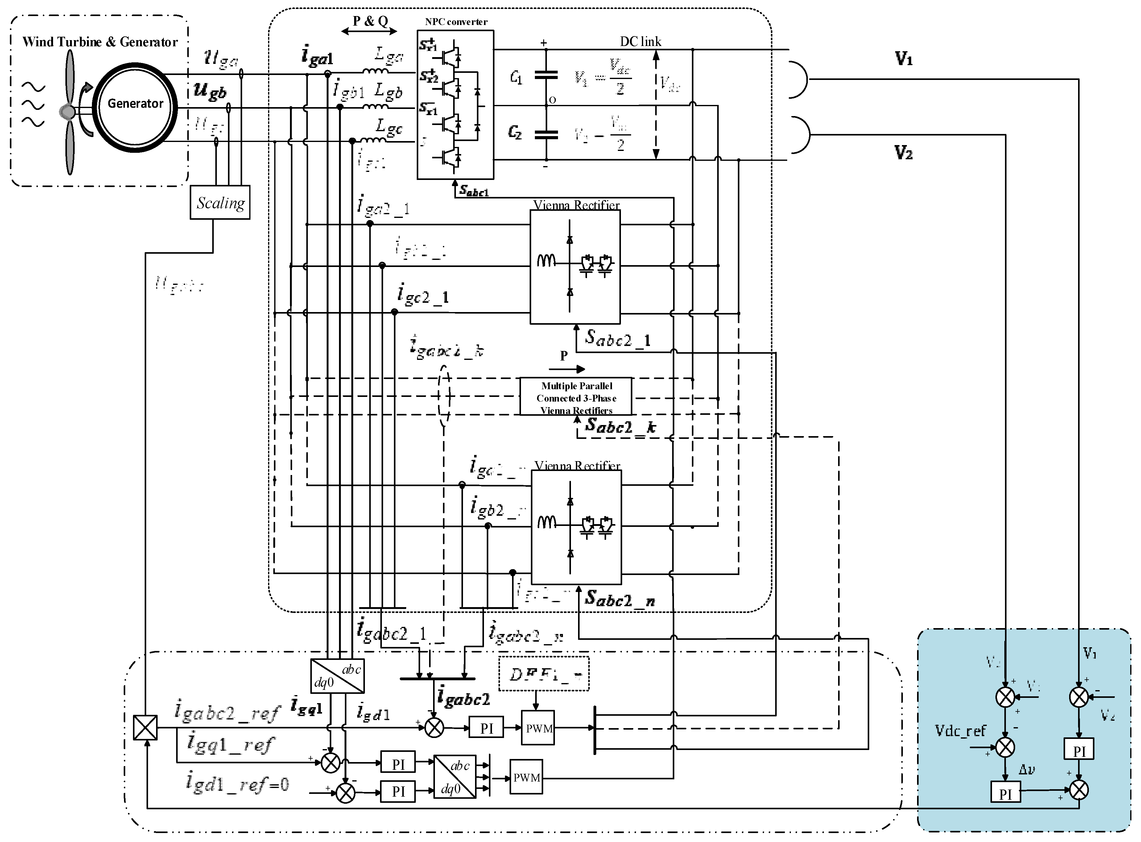
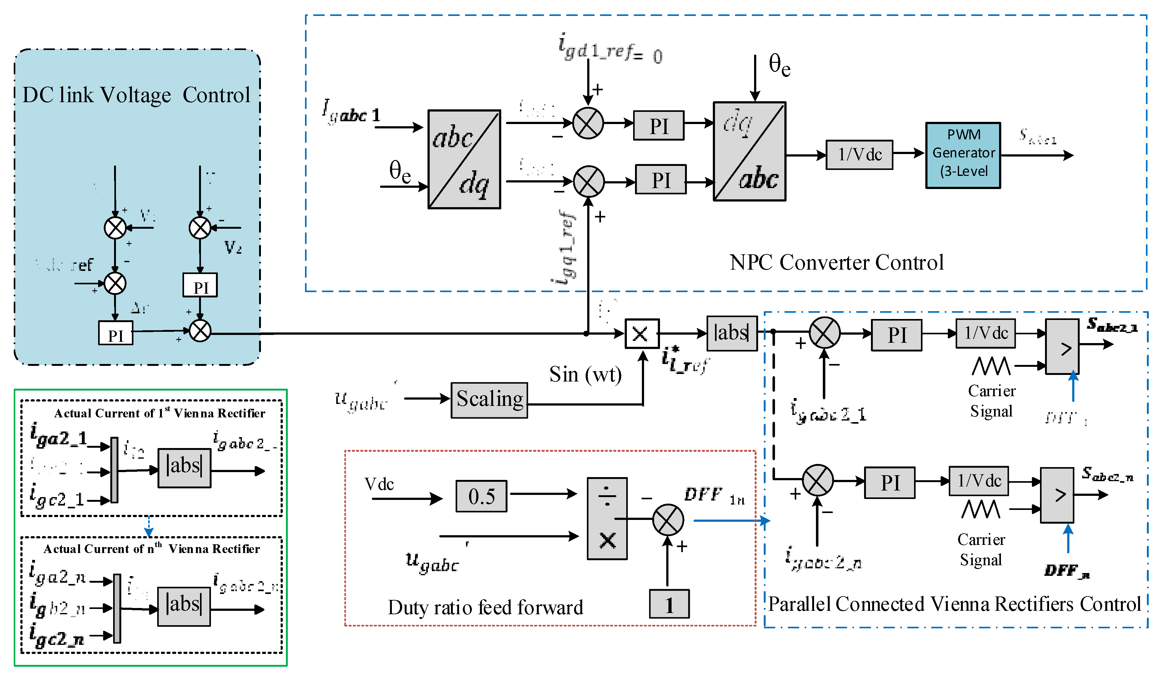
4. Control Strategy for the Proposed Converter

Wind energy produces dynamic alternating energy that is not acceptable by appliances and for long-distance transmission. Therefore, some control schemes on directly connected wind generator side converter require application to achieve a regulated energy. Some aspects of the modified hybrid control strategy for the new system were taken into account, such as good power factor, low THD of input current, and equal sharing of power in each parallel-connected module. The detail of the converter control is discussed in the following subsections:

4.1. NPC Converter Control

Figure 4 shows a simplified machine-side 3L-NPC converter control strategy. Voltage equation considering the input inductive filter in stationary ‘abc’ frame can be written as:
L g x d i x d t = U x U g x
Whereas, x = a , b , c  
ux = converter input voltage
ugx = grid supply voltage
Lgx = Input inductor
A commonly used voltage oriented control (VOC) has been applied for the 3L-NPC converter control. The classical type proportional-integral controllers (PI) method has been adopted to obtain good performance on dc values with small steady-state error [37]. Therefore, the stationary frame requires conversion into a synchronous d–q reference frame. Moreover, active power control is achived by setting the d-axis along with the grid voltage amplitude, whereas the q-axis has been set to zero. Active and reactive power can be controlled by the d and q-axis of the current, as illustrated in Equations (9) and (10).
P g = 3 2 v g d i g d
Q g = 3 2 v g d i g d
Park and Clark’s transformation is required to transform a stationary frame to a synchronous frame, and vice versa, to implement the VOC method. For the balanced amplitude of the sinusoidal waveform, the transformation from ‘dq0’ frame to ‘abc’ frame have done while using Equation (11).
( u g a u g b u g c ) = ( Cos ( θ e ) Sin ( θ e ) 1 2 Cos ( θ e 2 π 3 ) Sin ( θ e 2 π 3 ) 1 2 Cos ( θ e + 2 π 3 ) Sin ( θ e + 2 π 3 ) 1 2 ) ( u g d u g q 0 )
Similarly, voltage vectors in the ‘abc’ frame can also be directly transformed into the ‘dq0’ frame, according to the multiplication of the matric, as given by Equation (12).
( u g d u g q 0 ) = 2 3 ( Cos ( θ e ) Cos ( θ e 2 π 3 ) Cos ( θ e + 2 π 3 ) Sin ( θ e ) Sin ( θ e 2 π 3 ) Sin ( θ e + 2 π 3 ) 1 2 1 2 1 2 ) ( u g a u g b u g c )
The VOC approach consists of two closed-loop controllers, one for dc-link (outer loop) and the second one for current control (inner loop). In the outer loop control, two dc voltage controller have been taken to ensure the voltage balancing across each capacitors, among two voltage controllers one controller take the input error signal after comparing the reference dc voltage and the sum of measured individual capacitor voltages, while the other controller takes the error signal that was generated by the voltage difference across each capacitor to suppress the zero leakage current. The error that was generated by both controller was sent to two separate PI controllers for tuning. Finally, the sum of two PI controller results in a reference current i g d 1 _ r e f . Meanwhile, i g q 1 is set zero to deal with active power only. In Figure 4, both i s d 1 and i s q 1 are the feedback currents that were obtained by transforming the grid current into a rotating reference frame for inner loop control. The voltage controller sets the reference current i s d 1 _ r e f . Subsequently, the differences between the reference and actual currents are sent to the inner loop of the PI controller. The output of these current controller was provided to the PWM generator to obtain the appropriate signal. The outputs of the PWM generator were applied to the NPC switches for proper operation.

4.2. Vienna Rectifier Control

The voltage equations for input side of “n” number of Vienna rectifier can be written as
U g a = L d i s a 2 _ n d t   + U g A 0
    U g b = L d i s b 2 _ n d t   + U g B 0    
U g c = L d i s c 2 _ n d t   + U s C 0    
where U g A 0 , U g B 0 , and U g C 0 are the input voltages of the Vienna rectifier and n = 1,2,3….
Here, a simple current average control scheme has been implemented, where the current obtained from the voltage controller was set as a reference current i l * , which further divides in NPC and interleaved Vienna rectifiers. In Figure 4, the final reference current i l _ r e f * for all interleaved rectifiers was attained by multiplying i l * with sin ( w t )   . Whereas, sin ( w t ) represents the unit amplitude waveform of the generator voltage. The error obtained by taking the difference between the reference current i l * and measured current i s a b c 2 _ 1 is taken as an input to the current control. The PI controller is also selected for the inner current control of Vienna rectifier, which gives the output, like PWM duty cycle. Additionally, the duty ratio feedforward (DFF1_n) method has also been applied to improve the THD and waveform of the current at zero crossing. While designing the parameters of the PI controller bandwidth of the current control was kept wider than the outer voltage loop [37].

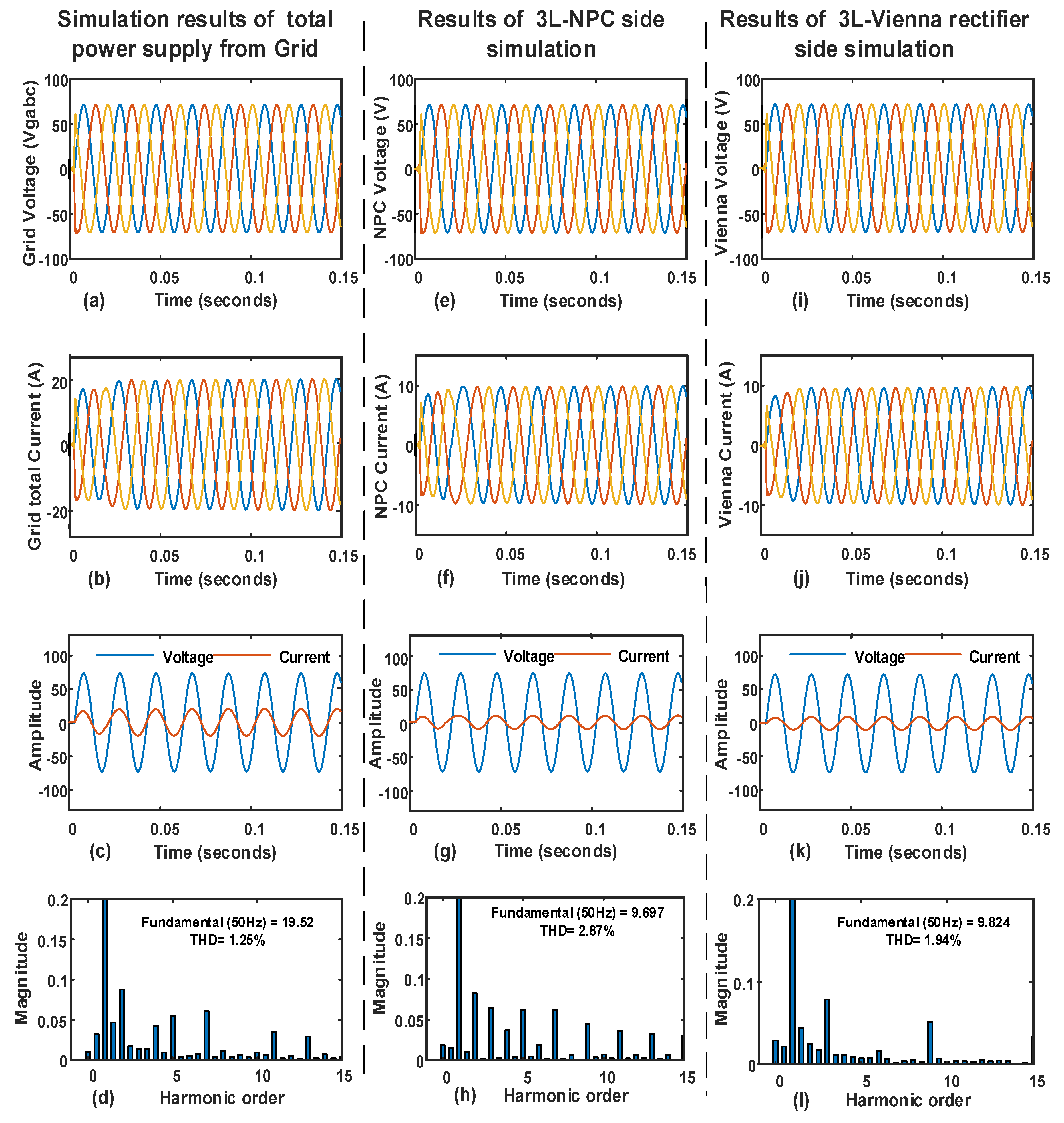
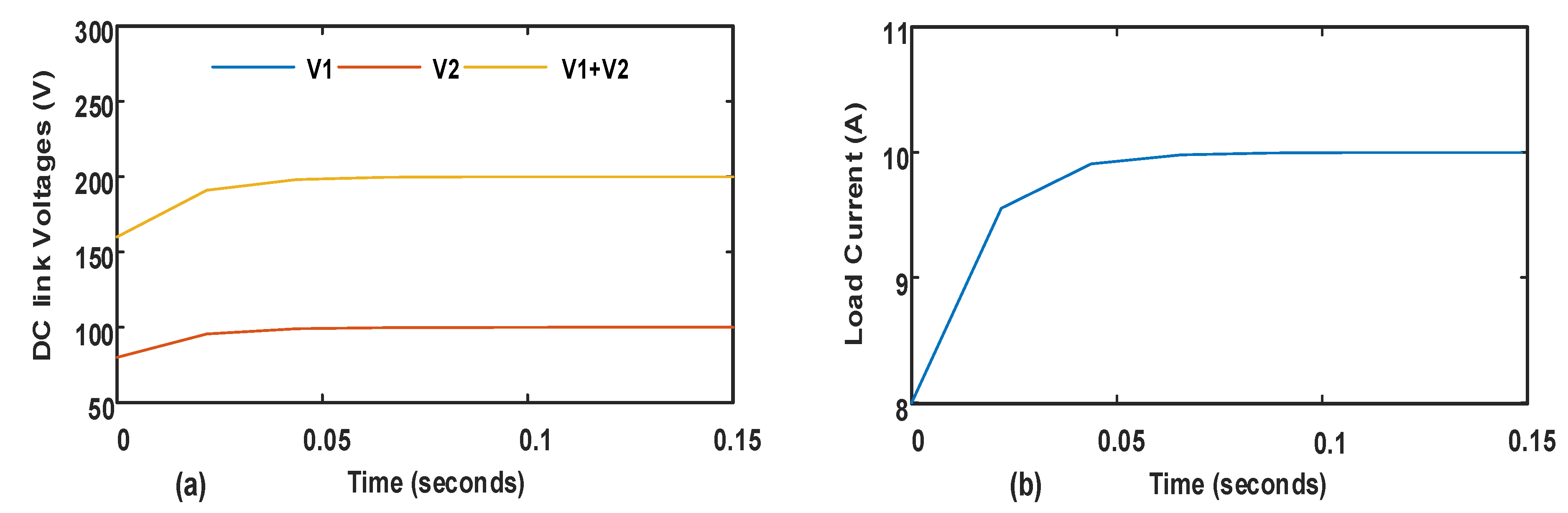
5. Simulation Results

A 2 KW three-phase MATLAB based simulation studies of two parallel-connected 3L-NPC and 3L-Vienna rectifier, as shown in Figure 5, has been performed in order to verify the performance of the proposed converter.
The recommended converter is best designed for multi-MW wind generator that is most prevalent in offshore wind energy applications. For the purpose of validation three-phase, electric grid as a generated source was considered to implement the proposed converter. All of the parameters that were used by the simulation are mentioned in Table 4.
Figure 6a represents an applied three-phase voltage of 50 Vrms from the grid and Figure 6e,i denote waveforms of voltage across two parallel-connected 3L-NPC and Vienna rectifier, respectively. Figure 6b illustrates the total current drawn from the source, which is exactly the sum of both the NPC and Vienna rectifier. Similarly, half of the total current in Figure 6f,j justify the division of current equally in each parallel connected converter that also satisfies the control main purpose. Figure 6c,g,k show that the phase among applied voltage and current are the same, which means their power factor nearly unity. Figure 6d,h,l are a representation of THD of total current, bidirectional converter current and the Vienna rectifier current, respectively, which also results that the Vienna rectifier has the lowest THD when compared to NPC converter. Therefore, the Vienna rectifier was also selected for the collection of efficient DC energy from wind energy.
The blue and red legends in Figure 7a represent voltage across C1 and C2, while the yellow label represents a total DC-link voltage. The total dc current drawn by the resistive load is shown in Figure 7b.

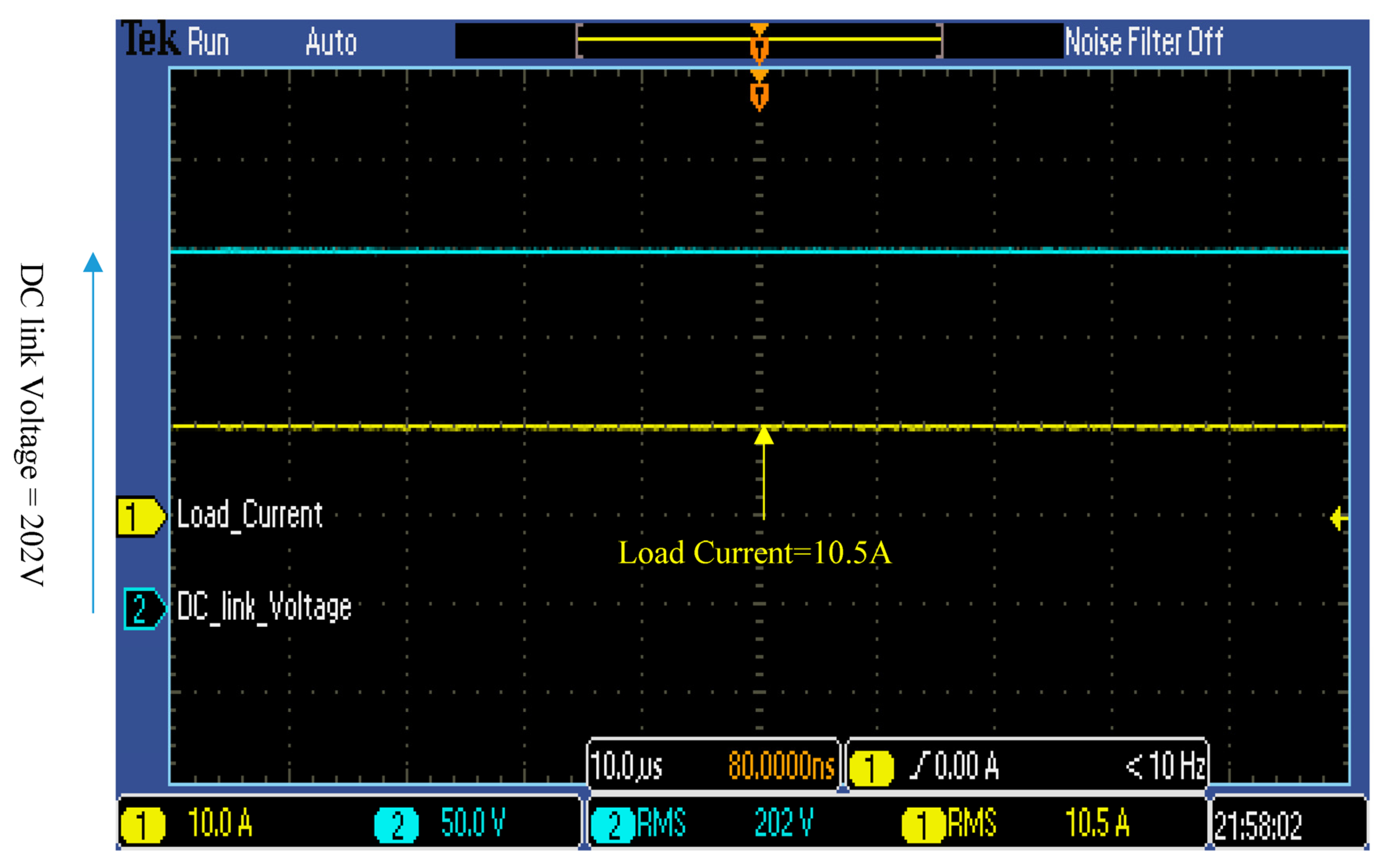
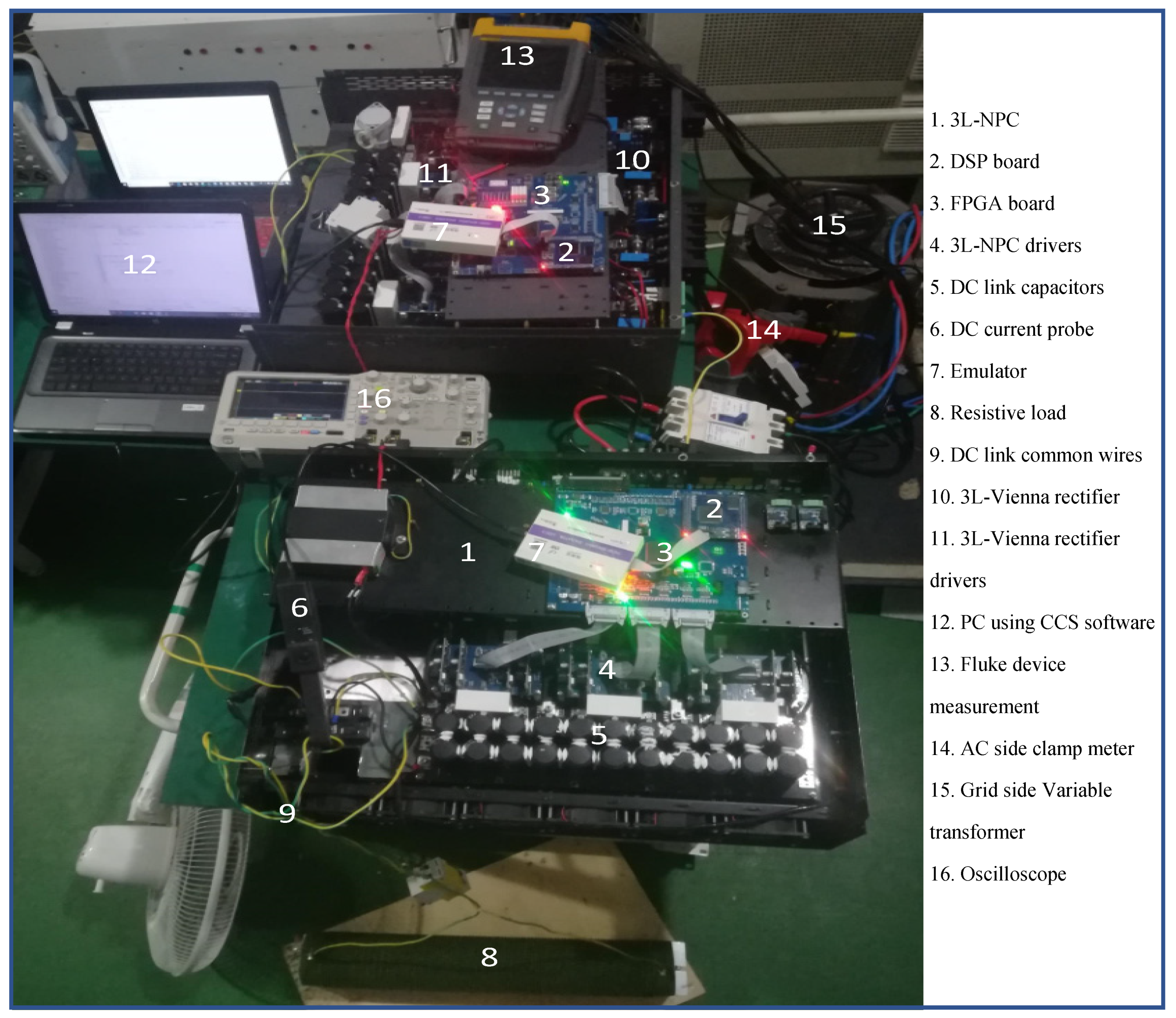
6. Experimental Results

The proposed hybrid converter consists of a three-phase Vienna rectifier that was interleaved with 3L-NPC converter with total power of 2-KW was designed and implemented as per the specifications mentioned in Table 4. Figure 8 shows the requisite experimental results of the system, as depicted in Figure 5. As a Page: 9total grid supply voltage to the parallel connected converters will be same as showm in is Figure 8a–c. Figure 8a–d epitomize the results of total power that is supplied by the grid to both parallel-connected converters. 3.2% THD of total current also meet the IEEE standard. Figure 8b,f,j show the waveforms of total current, 3L-NPC and Vienna rectifier respectively. Half of the total current in 3L-NPC and Vienna rectifier show that the total system power divided among parallel-connected converters.
The detailed data in Figure 8c,g,k also verify that the total power has equally distributed in both parallel-connected converters, which verifies that the control algorithm works well in power-sharing. The currents drawn by NPC and Vienna rectifier, as shown in Figure 8h,l with THD 4.7% and 2.5%, respectively, also follow the IEEE standard.Moreover, the Vienna rectifier has less THD as compared to 3L-NPC, which also leads towards increased efficiency.
In Figure 9. the blue line shows the experimental results of the total dc-link voltage, while the yellow line represents a load current, as mentioned in table-IV. Finally, the whole setup of the implemented converter is shown in Figure 10 by labeling the main parts.

7. Conclusions

A novel bi-directional converter, especially for multi-MW wind generator for offshore wind energy conversion applications, was designed. This converter has the ability to handle a wide range of power in MW with thousands of ampere current by adding parallel circuitry of ‘n’ number of Vienna rectifiers with a single module of three-phase 3L-NPC converter. Moreover, the designed converter has a lower number of power devices, which leads towards cost-effectivness, a reduction in switching losses, as well as high power density system as compared to the conventional parallel-connected 3L-NPC converters. A simple hybrid control scheme consists of a VOC for 3L-NPC and current average control technique with the addition of duty ratio feed-forward for Vienna rectifier control to improve the current distortion was also investigated. Equally distributed power in Vienna rectifier and 3L-NPC converter verified the control performance. The proposed converter with a control scheme also verified that the Vienna rectifier has unity power factor (PF) and low THD factor as compared to 3L-NPC. The simulation and experimental results of a deliberated 2-KW system verified the fast dynamic response, good power factor (PF), and current THD less than 5%.

Author Contributions

M.L. and G.Y. conceived and designed the study; M.L. preformed experiments and edited the draft with guidance from G.Y and L.Z. L.Z. checked the language and style of the manuscript. T.Z. and A.L. made a contribution to the revisions of manuscript.

Funding

This research was supported by the Shanghai Natural Science Foundation (SNSF) under grant 18ZR1418400.

Acknowledgments

We thank all the journal editors and the reviewers for their valuable feedback and constructive comments that have contributed to improving this manuscript.

Conflicts of Interest

The authors declare no conflict of interest.

References

  1. Burton, D.S.T.; Jenkins, N.; Bossanyi, E. Wind Energy Handbook; John Wiley & Sons Ltd.: Chichester, UK, 2001. [Google Scholar]
  2. Doubrawa Moreira, P.; Scott, G.N.; Musial, W.D.; Kilcher, L.F.; Draxl, C.; Lantz, E.J. Offshore Wind Energy Resource Assessment for Alaska; No. NREL/TP-5000-70553; National Renewable Energy Lab.(NREL): Golden, CO, USA, 2018.
  3. National Development and Reform Commission. Available online: http://finance.sina.com.cn/roll/2017-04-25/doc-ifyepnea4974842.shtml (accessed on 25 April 2017).
  4. Wang, S.; Wang, S. Impacts of wind energy on environment: A review. Renew. Sustain. Energy Rev. 2015, 49, 437–443. [Google Scholar] [CrossRef]
  5. Global Wind Energy Council (GWEC). Global Wind Report: Annual Market Update. April 2017. Available online: http://www.gwec.net (accessed on 14 January 2018).
  6. Blaabjerg, F.; Ma, K. Future on power electronics for wind turbine systems. IEEE J. Emerg. Sel. Top. Power Electron. 2013, 1, 139–152. [Google Scholar] [CrossRef]
  7. Blaabjerg, F.; Liserre, M.; Ma, K. Power electronics converters for wind turbine systems. IEEE Trans. Ind. Appl. 2012, 48, 708–719. [Google Scholar] [CrossRef]
  8. Dos Santos, E.C.; Rocha, N.; Jacobina, C.B. Suitable single-phase to three-phase AC-DC-AC power conversion system. IEEE Trans. Power Electron. 2015, 30, 860–870. [Google Scholar] [CrossRef]
  9. Wang, G.; Konstantinou, G.; Townsend, C.D.; Pou, J.; Vazquez, S.; Demetriades, G.D.; Agelidis, V.G. A review of power electronics for grid connection of utility-scale battery energy storage systems. IEEE Trans. Sustain. Energy 2016, 7, 1778–1790. [Google Scholar] [CrossRef]
  10. Schnitzer, D.; Lounsbury, D.; Carvallo, J.; Deshmukh, R.; Apt, J.; Kammen, D.M. Microgrids for Rural Electrification: A Critical Review of Best Practices Based on Seven Case Studies; UN Found: New York, NY, USA, 2014. [Google Scholar]
  11. Shaahid, S.; El-Amin, I. Techno-economic evaluation of off-grid hybrid photovoltaic–diesel–battery power systems for rural electrification in Saudi Arabia—A way forward for sustainable development. Renew. Sustain. Energy Rev. 2009, 13, 625–633. [Google Scholar] [CrossRef]
  12. Sokolovs, A.; Grigans, L. Front-end converter choice considerations for PMSG-based micro-wind turbines. In Proceedings of the 56th International Scientific Conference on Power and Electrical Engineering of Riga Technical University (RTUCON), Riga. Latvia, 14 October 2015; pp. 1–6. [Google Scholar]
  13. Vilathgamuwa, D.M.; Jayasinghe, S.D.G. Rectifier systems for variable speed wind generation-a review. In Proceedings of the 2012 IEEE International Symposium on Industrial Electronics, Hangzhou, China, 28–31 May 2012; pp. 1058–1065. [Google Scholar]
  14. Salgado-Herrera, N.; Campos-Gaona, D.; Anaya-Lara, O.; Medina-Rios, A.; Tapia-Sánchez, R.; Rodríguez-Rodríguez, J. THD reduction in wind energy system using type-4 wind turbine/PMSG applying the active front-end converter parallel operation. Energies 2018, 11, 2458. [Google Scholar] [CrossRef]
  15. Ma, K.; Blaabjerg, F. The impact of power switching devices on the thermal performance of a 10 MW wind power NPC converter. Energies 2012, 5, 2559–2577. [Google Scholar] [CrossRef]
  16. Ventosa-Cutillas, A.; Montero-Robina, P.; Umbría, F.; Cuesta, F.; Gordillo, F. Integrated Control and Modulation for Three-Level NPC Rectifiers. Energies 2019, 12, 1641. [Google Scholar] [CrossRef]
  17. Luqman, M.; Yao, G.; Zhou, L.; Lamichhane, A. Analysis of Variable Speed Wind Energy Conversion System With PMSG and Vienna Rectifier. In Proceedings of the 2019 14th IEEE Conference on Industrial Electronics and Applications, Xi’an, China, 19–21 June 2019; pp. 1296–1301. [Google Scholar]
  18. Nasiri, M.; Mohammadi, R. Peak Current Limitation for Grid Side Inverter by Limited Active Power in PMSG-Based Wind Turbines During Different Grid Faults. IEEE Trans. Sustain. Energy 2017, 26, 3–12. [Google Scholar] [CrossRef]
  19. Hou, C.C.; Cheng, P.T. Experimental Verification of the Active Front-End Converters Dynamic Model and Control Designs. IEEE Trans. Power Electron. 2011, 26, 1112–1118. [Google Scholar] [CrossRef]
  20. Shen, L.; Bozhko, S.; Asher, G.; Patel, C.; Wheeler, P. Active DC-Link Capacitor Harmonic Current Reduction in Two-Level Back-to-Back Converter. IEEE Trans. Power Electron. 2016, 31, 6947–6954. [Google Scholar] [CrossRef]
  21. Blaabjerg, F.; Ma, K. High power electronics: Key technology for wind turbines. Power Electron. Renew. Energy Syst. Transp. Ind. Appl. 2014, 18, 136–159. [Google Scholar]
  22. Luqman, M.; Yao, G.; Zhou, L.; Yang, D.; Lamichhane, A. Study and Implementation of a Cost-Effective 3L-Active Rectifier for DC Collection in WECS. EDP Sciences. In Proceedings of the 2019 4th International Conference on Advances in Energy and Environment Research (ICAEER 2019), Shanghai, China, 16–18 August 2019. [Google Scholar]
  23. Xu, Z.; Li, R.; Xu, D. Control of parallel multi-rectifiers for a direct drive permanent-magnet wind power generator. IEEE Trans. Ind. Appl. 2013, 49, 1687–1696. [Google Scholar] [CrossRef]
  24. Khan, S.U.; Maswood, A.I.; Tariq, M.; Tafti, H.D.; Tripathi, A. Parallel Operation of Unity Power Factor Rectifier for PMSG Wind Turbine System. IEEE Trans. Ind. Appl. 2019, 55, 721–731. [Google Scholar] [CrossRef]
  25. Baroudi, J.A.; Dinavahi, V.; Knight, A.M. A review of power converter topologies for wind generators. Renew. Energy 2007, 32, 2369–2385. [Google Scholar] [CrossRef]
  26. Liserre, M.; Cárdenas, R.; Molinas, M.; Rodriguez, J. Overview of Multi-MW Wind Turbines and Wind Parks. IEEE Trans. Ind. Electron. 2011, 58, 1081–1095. [Google Scholar] [CrossRef]
  27. Carrasco, J.M.; Franquelo, L.G.; Bialasiewicz, J.T.; Galvan, E.; Guisado, R.C.P.; Martín Prats, M.D.; Leon, J.I.; Moreno-Alfonso, N. PowerElectronic Systems for the Grid Integration of Renewable Energy Sources: A Survey. IEEE Trans. Ind. Electron. 2006, 53, 1002–1016. [Google Scholar] [CrossRef]
  28. Chen, Z.; Guerrero, J.M.; Blaabjerg, F. A Review of the State of the Art of Power Electronics for Wind Turbines. IEEE Trans. Power Electron. 2009, 24, 1859–1875. [Google Scholar] [CrossRef]
  29. Wu, B.; Lang, Y.; Zargari, N.; Kouro, S. Power Conversion and Control of Wind Energy Systems; John Wiley & Sons: Hoboken, NJ, USA, 2011 26 September; Volume 76. [Google Scholar]
  30. Thandapani, T.; Karpagam, R.; Paramasivam, S. Comparative study of VIENNA rectifier topologies. Int. J. Power Electron. 2015, 7, 147–165. [Google Scholar] [CrossRef]
  31. Lamichhane, A.; Zhou, L.; Yao, G.; Luqman, M. LCL Filter Based Grid-Connected Photovoltaic System with Battery Energy Storage. In Proceedings of the 2019 14th IEEE Conference on Industrial Electronics and Applications, Xi’an, China, 19–21 June 2019. [Google Scholar]
  32. Hang, L.; Zhang, M. Constant power control-based strategy for Vienna-type rectifiers to expand operating area under severe unbalanced grid. IET Power Electron. 2014, 7, 41–49. [Google Scholar] [CrossRef]
  33. Teshnizi, H.M.; Moallem, A.; Zolghadri, M.; Ferdowsi, M. A dual-frame hybrid vector control of vector modulated VIENNA I rectifier for unity power factor operation under unbalanced mains condition. In Proceedings of the 2008 Twenty-Third Annual IEEE Applied Power Electronics Conference and Exposition, Austin, TX, USA, 24 February 2008. [Google Scholar]
  34. Youssef, N.B.H.; Al-Haddad, K.; Kanaan, H.Y. Implementation of a new linear control technique based on experimentally validated small-signal model of three-phase three-level boost-type Vienna rectifier. IEEE Trans. Ind. Electron. 2008, 55, 1666–1676. [Google Scholar] [CrossRef]
  35. Chen, H.; Aliprantis, D.C. Analysis of squirrel-cage induction generator with Vienna rectifier for wind energy conversion system. IEEE Trans. Energy Convers. 2011, 26, 967–975. [Google Scholar] [CrossRef]
  36. Win, M.M.; Tin, T. Engineering, Voltage Source Converter Based HVDC Overhead Transmission System. IJSETR Int. J. Sci. Eng. Technol. Res. 2014, 3, 3909–3914. [Google Scholar]
  37. Kwon, Y.D.; Park, J.H.; Lee, K.B. Improving Line Current Distortion in Single-Phase Vienna Rectifiers Using Model-Based Predictive Control. Energies 2018, 11, 1237. [Google Scholar] [CrossRef]
Figure 1. (a) Two-level converter; (b) Three-Level NPC converter; (c) Three-level Vienna rectifier.
Energies 12 04167 g001
Figure 2. Conventional scheme of 3L-NPC converter with multi-MW wind generator.
Energies 12 04167 g002
Figure 3. Proposed hybrid converter for multi-MW wind generator.
Energies 12 04167 g003
Figure 4. Control strategy of a proposed hybrid converter.
Energies 12 04167 g004
Figure 5. Diagram of simulated and Implemented system.
Energies 12 04167 g005
Figure 6. Simulation results of a 2-KW proposed hybrid converter.
Energies 12 04167 g006
Figure 7. Simulation results of DC link voltage control and load current.
Energies 12 04167 g007
Figure 8. Experimental results of a 2-KW proposed hybrid converter.
Energies 12 04167 g008
Figure 9. Experimental results of DC link voltage and load current.
Energies 12 04167 g009
Figure 10. Experimental setup of two parallel-connected 3L-NPC and Vienna rectifier.
Energies 12 04167 g010
Table 1. Comparison of the number of devices used.
Converter TypeNumber of DiodesNumber of IGBTsNumber of IGBTs DriversTotal Number of Devices
Two-level66618
Three-level NPC18121242
3L-Vienna rectifier126624
Table 2. Configurations and state of 3L-NPC converter.
Conf.     S x 1 +             S x 2 +             S x 1             S x 2             V o u t        
1st 11001100     + V d c     / 2    
2nd 011001100
3rd 00110011     V d c     / 2    
Table 3. Switching conditions for three-phase Vienna Rectifier.
S a     S b         S c         V a n         V b n         V c n    
0 0 0     + Vo / 2         Vo / 2         Vo / 2    
0 0 1     + Vo / 2         Vo / 2     0
0 1 0     + Vo / 2     0     Vo / 2    
0 1 1     + Vo / 2     0 0
1 0 0 0     Vo / 2         Vo / 2    
1 0 1 0     Vo / 2     0
1 1 0 0     0         Vo / 2    
1 1 1 0 0 0
Table 4. Data used for Simulation and Experiment.
ParameterValue
Total power 2 KW
Grid side voltage50 Vrms
DC- link voltage200 V
Grid frequency50 Hz
Switching frequency15 KHz
Inductor (3L-NPC/Vienna)300 uH
C1/C2 capacitor9020 uF

