A Modified DSC-Based Grid Synchronization Method for a High Renewable Penetrated Power System Under Distorted Voltage Conditions


Abstract
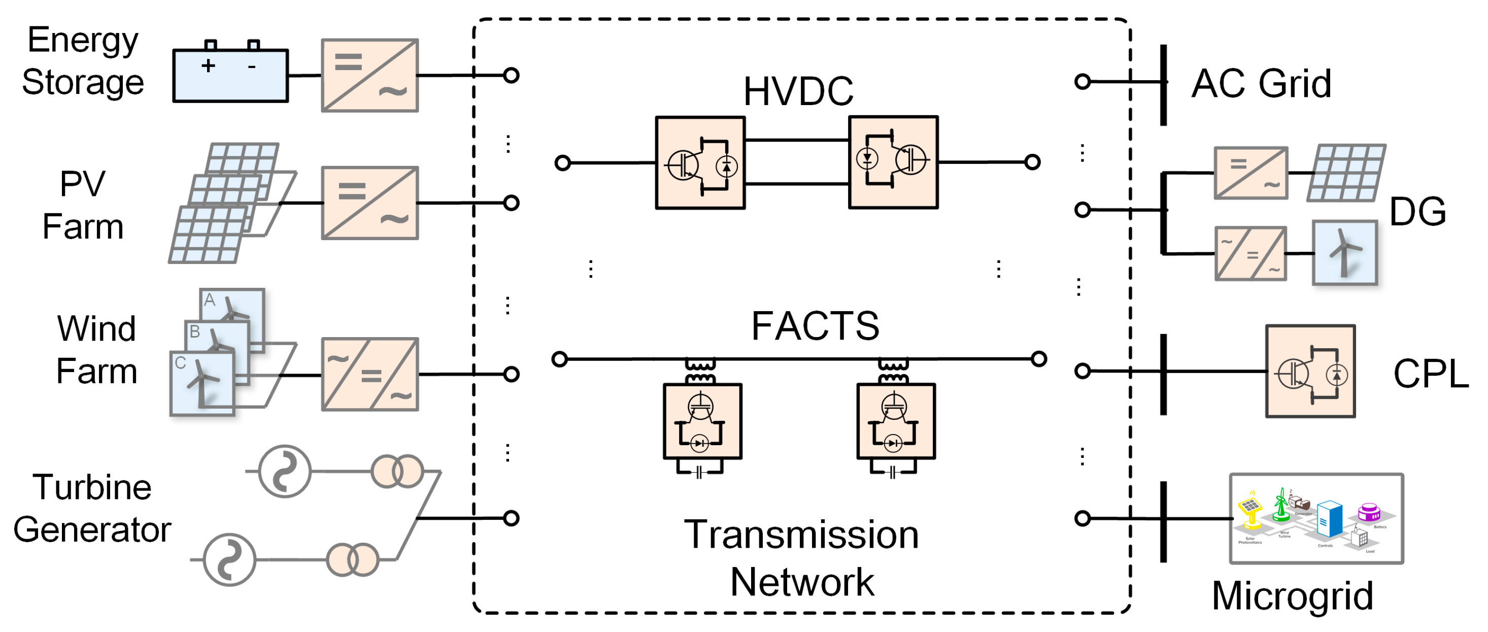
:1. Introduction
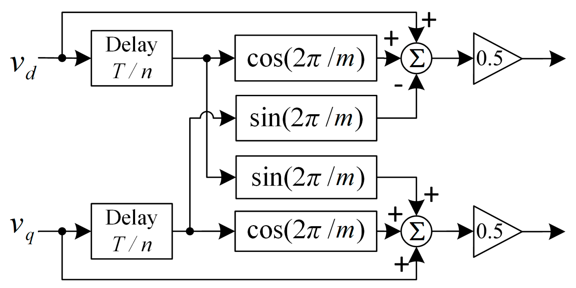
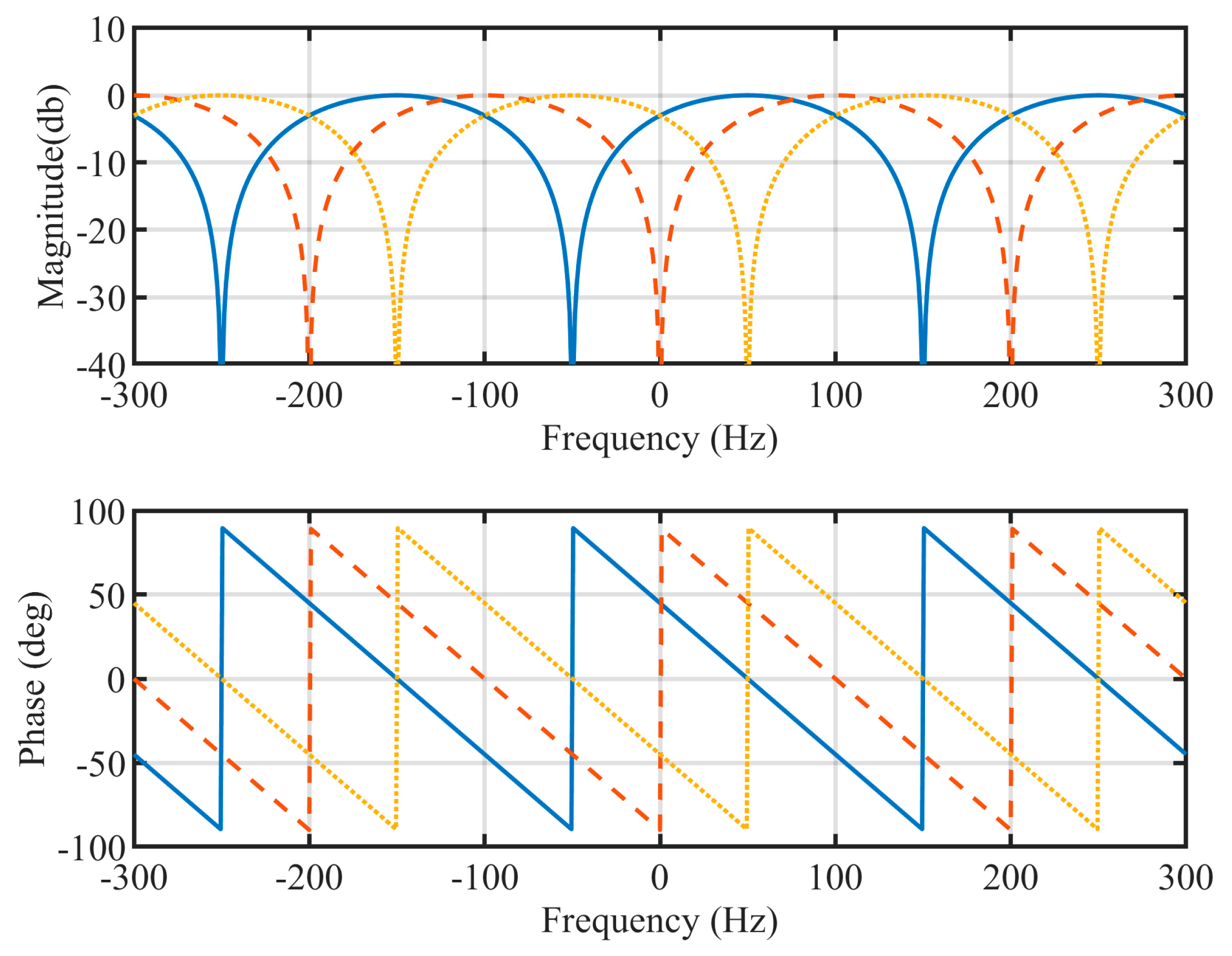
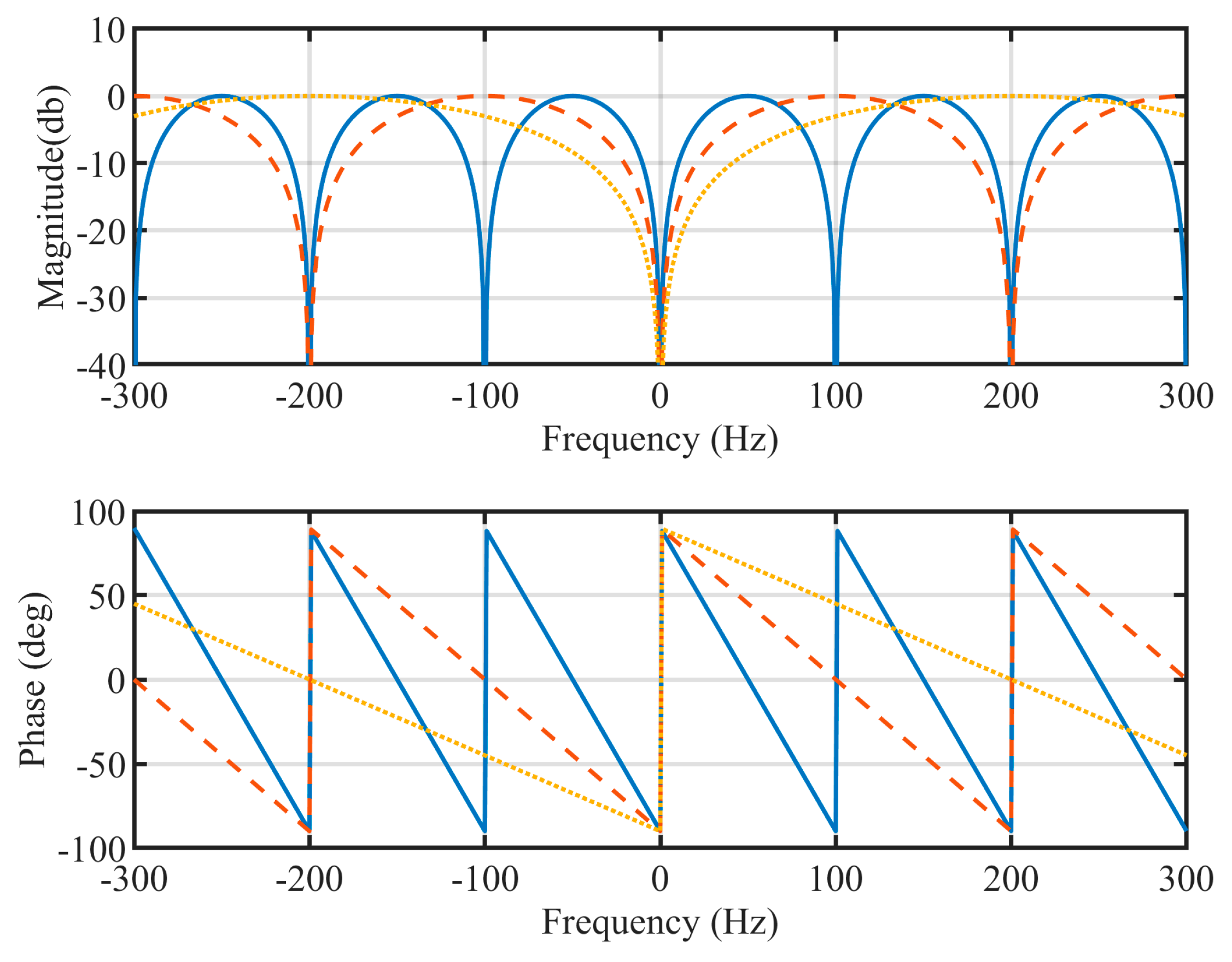
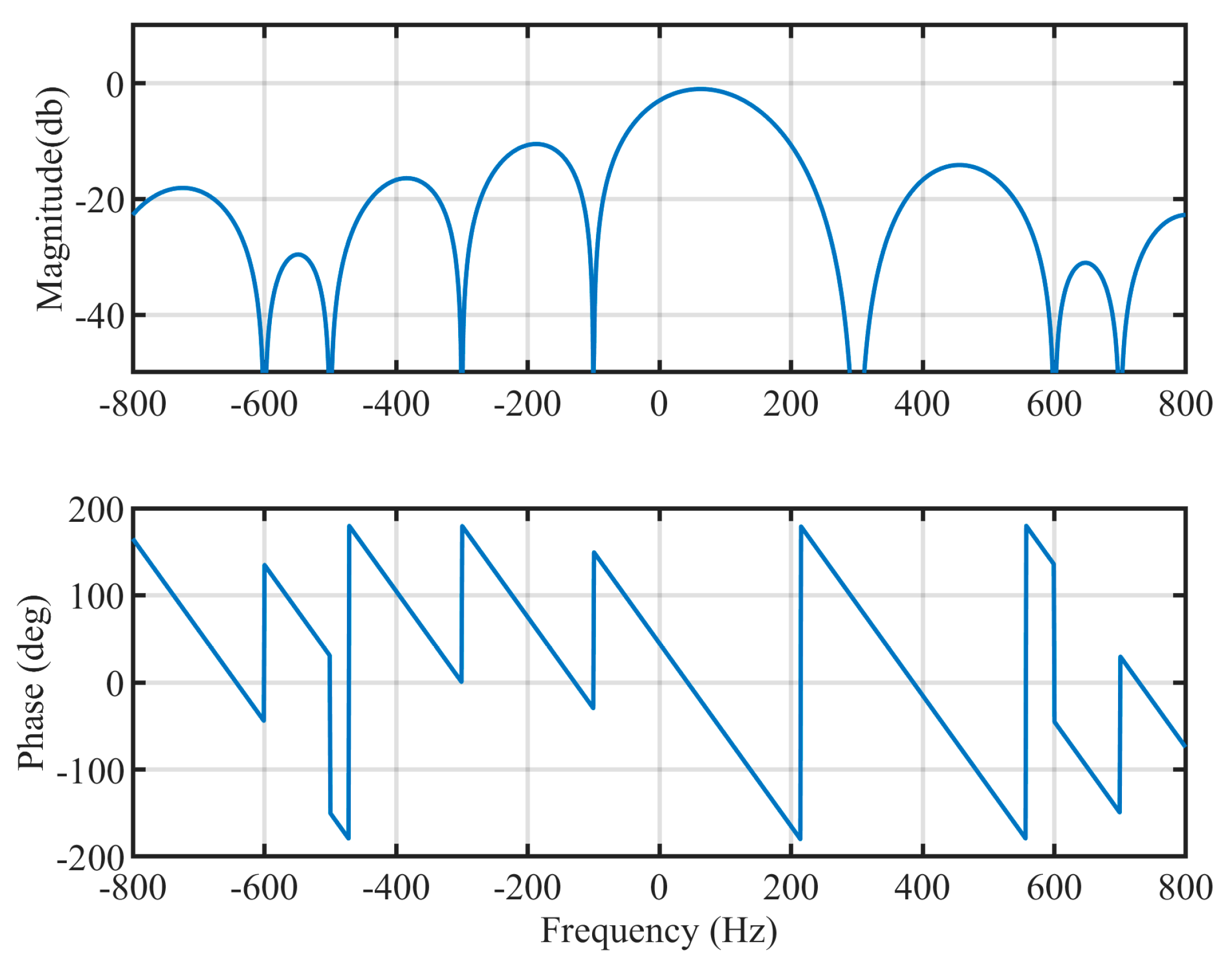
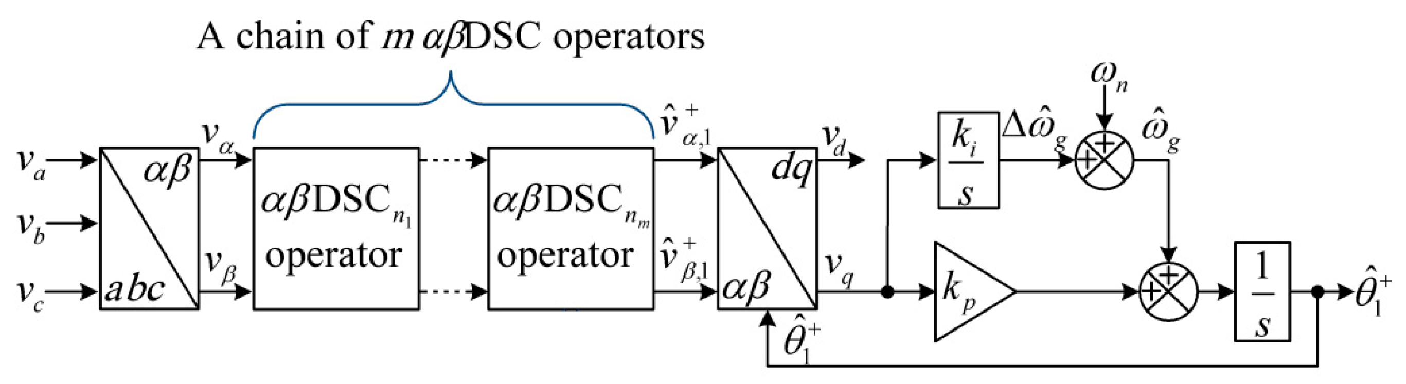
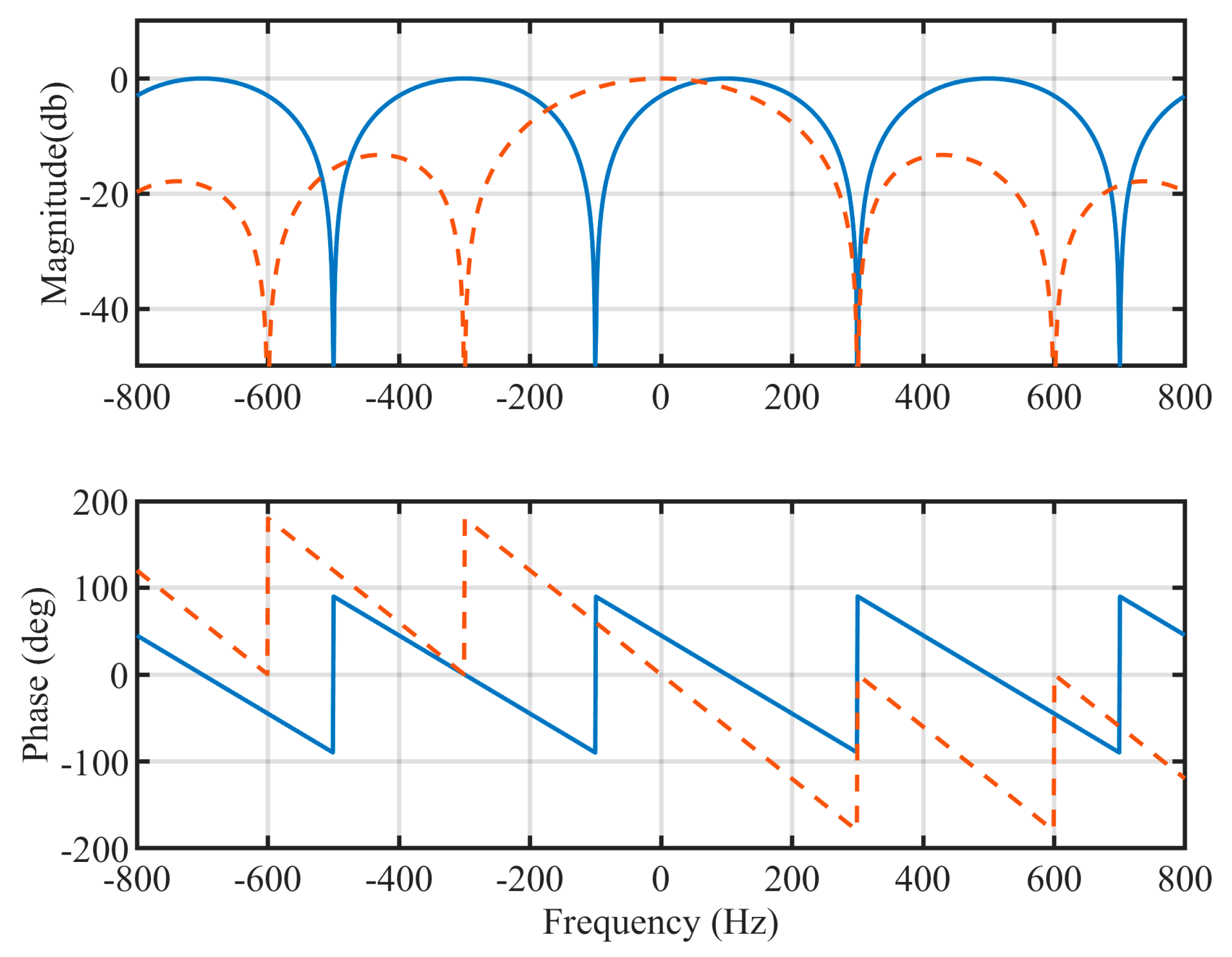
2. Modified Delay Signal Cancellation Operator
3. The Proposed PLL Structure
3.1. The Component Analysis of Distorted Grid Voltages
3.2. The Hybrid Filtering Stage
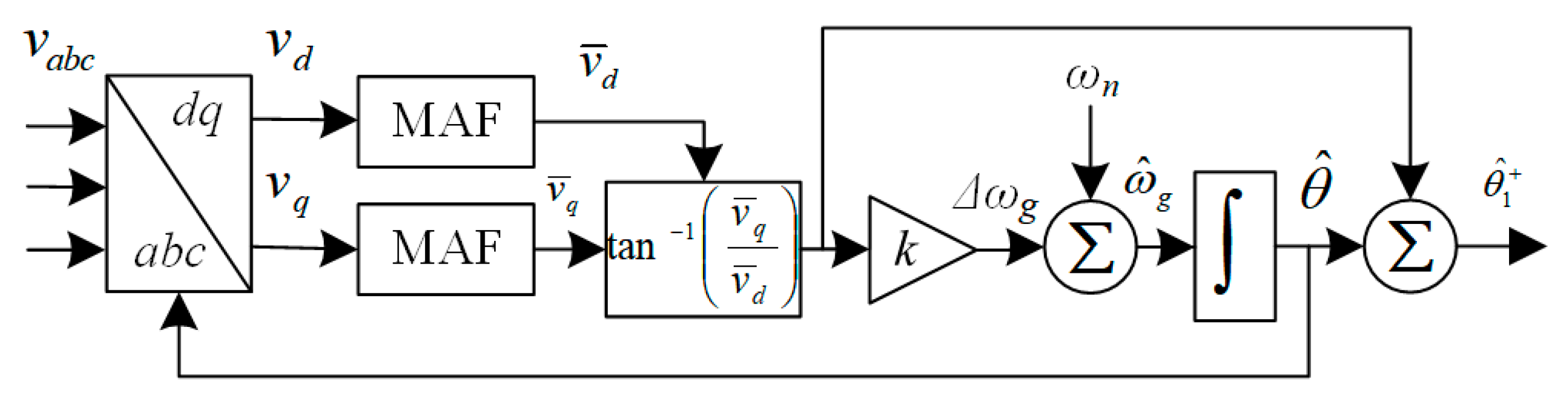
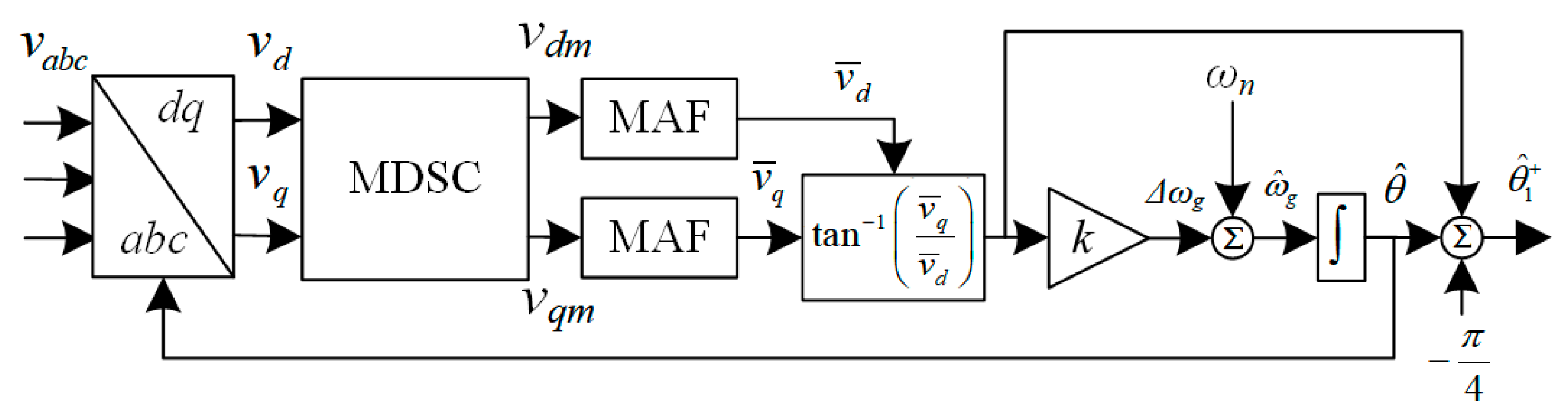
3.3. The Proposed PLL Structure
4. Mathematics Model and Parameters Design Procedure
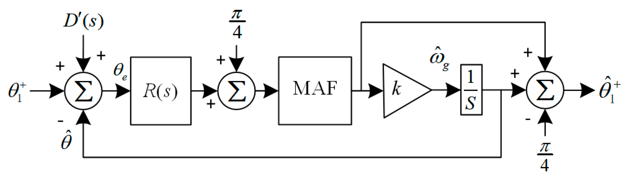
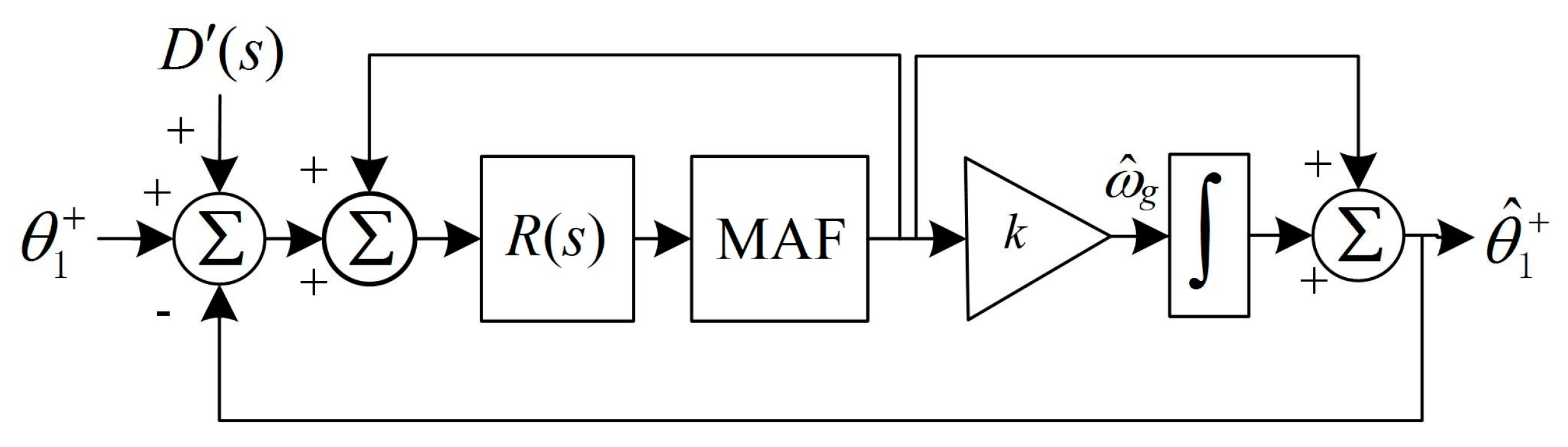
4.1. Mathematics Model
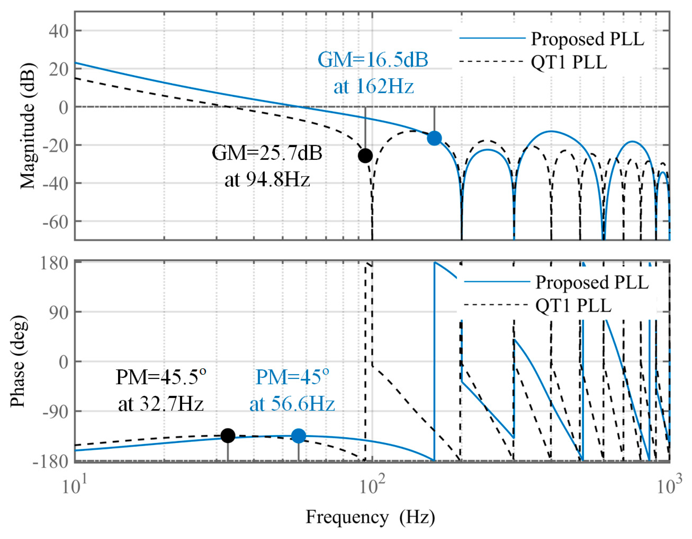
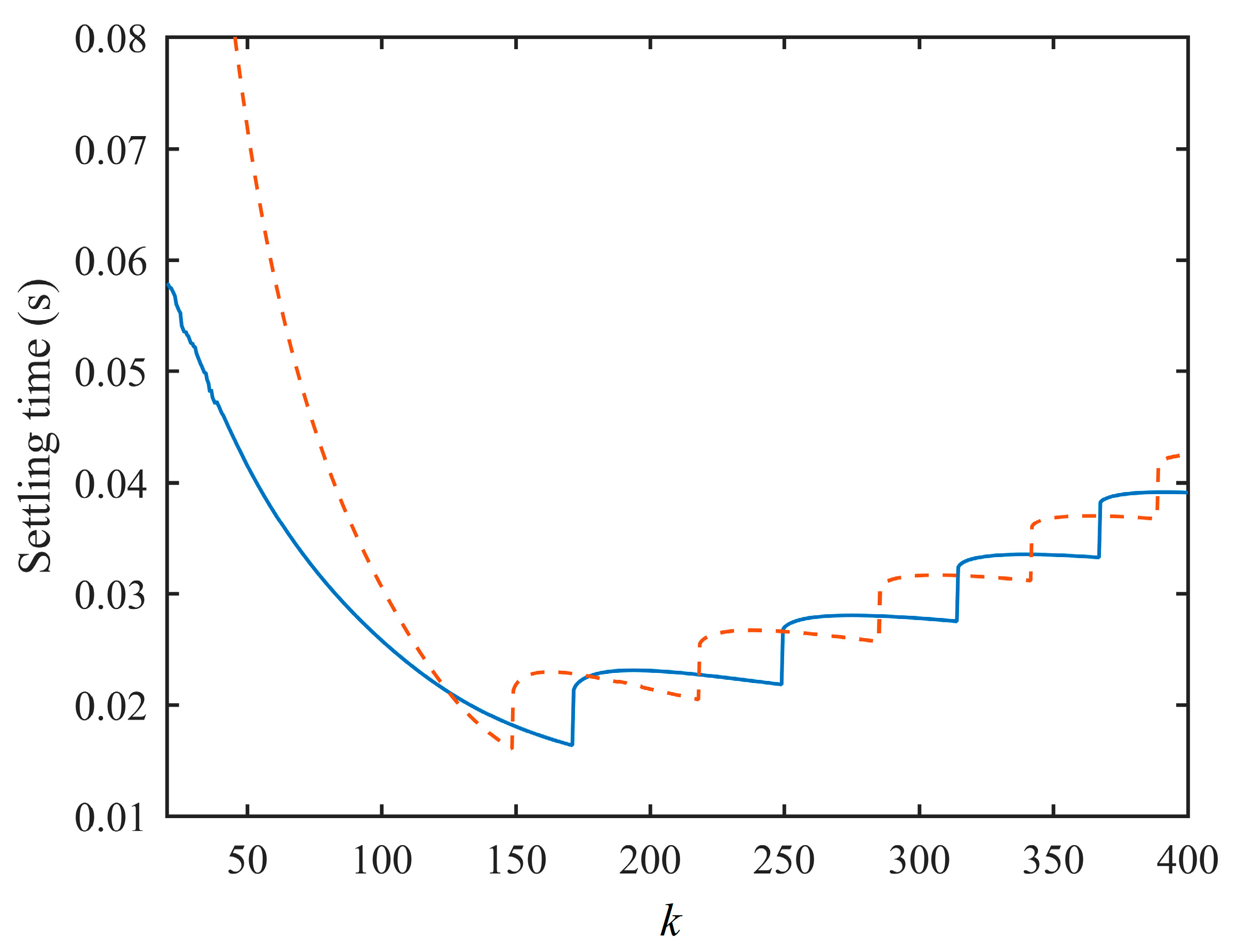
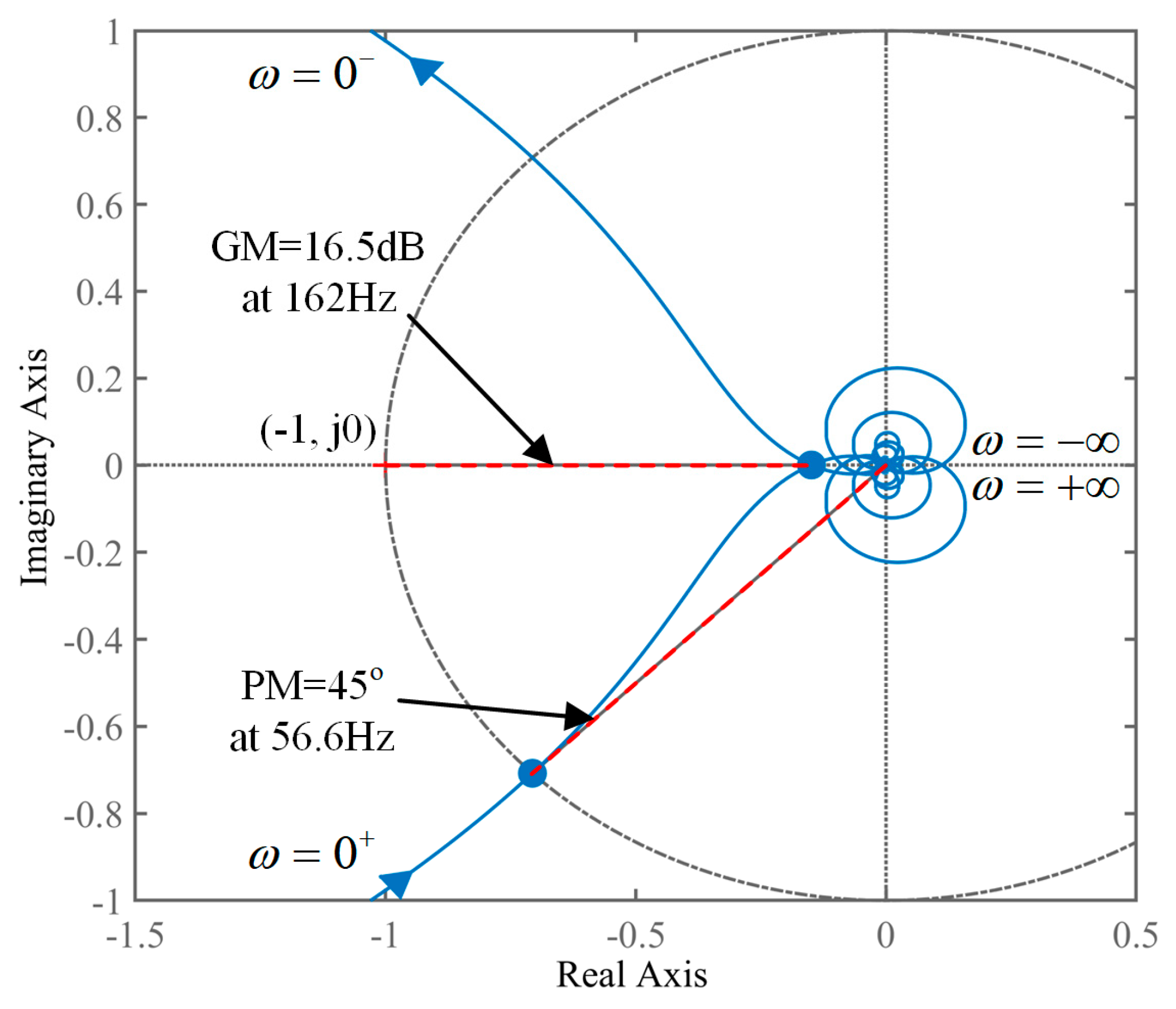
4.2. Parameter Design Guidelines and Stability Analysis
4.3. Assessment of Model Accuracy
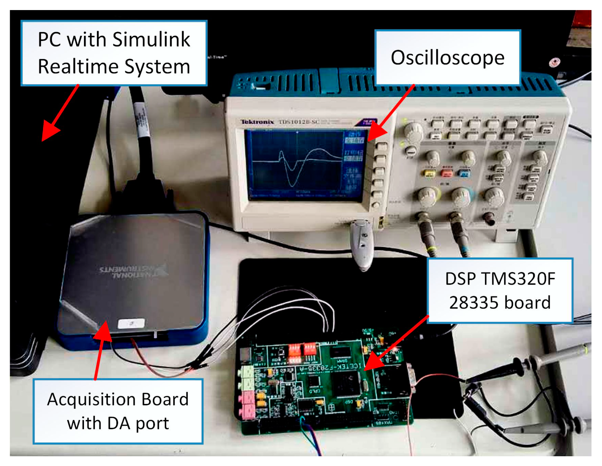
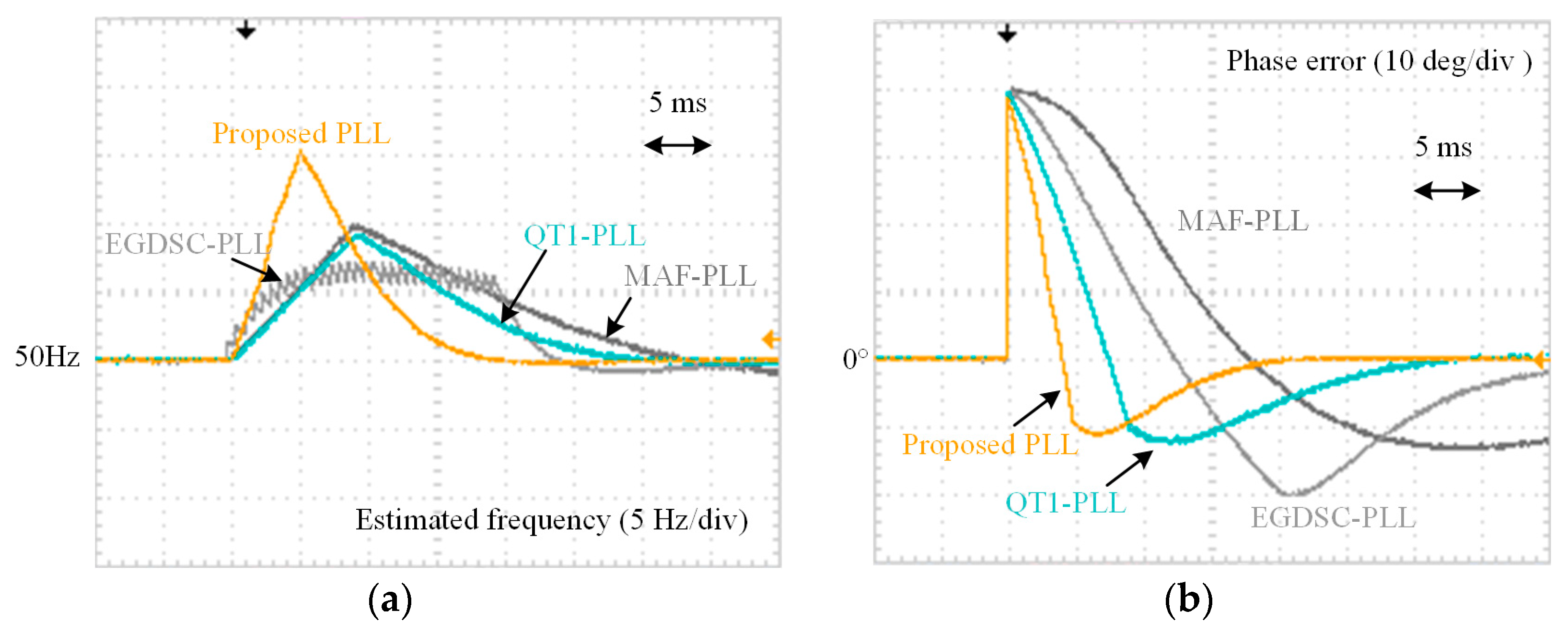
5. Experimental Results
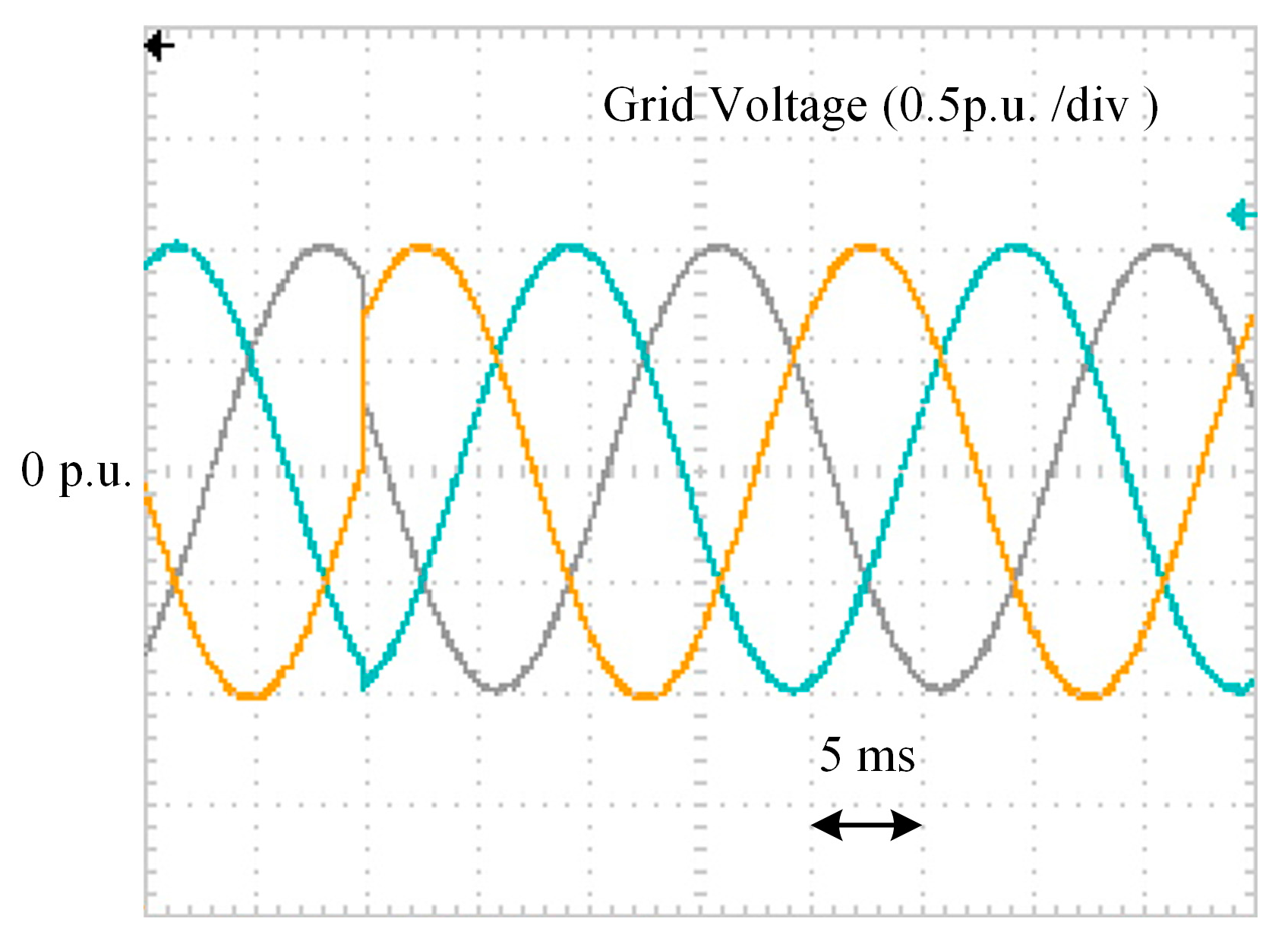
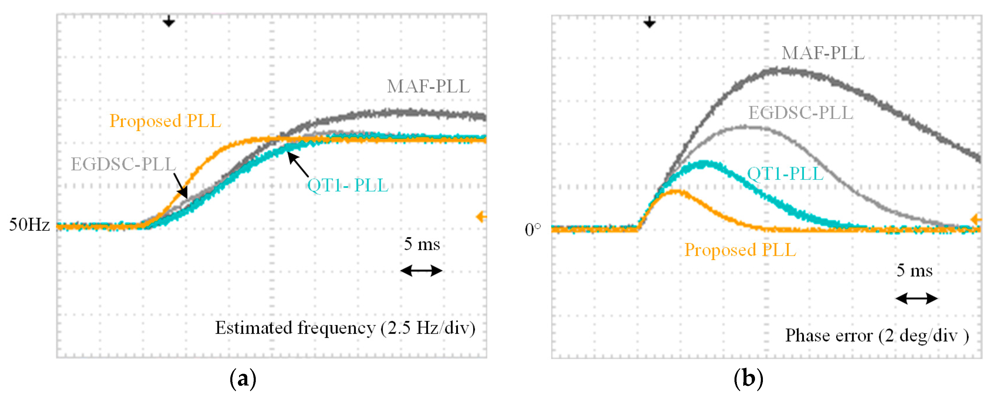
5.1. Test Case 1: Phase Jump
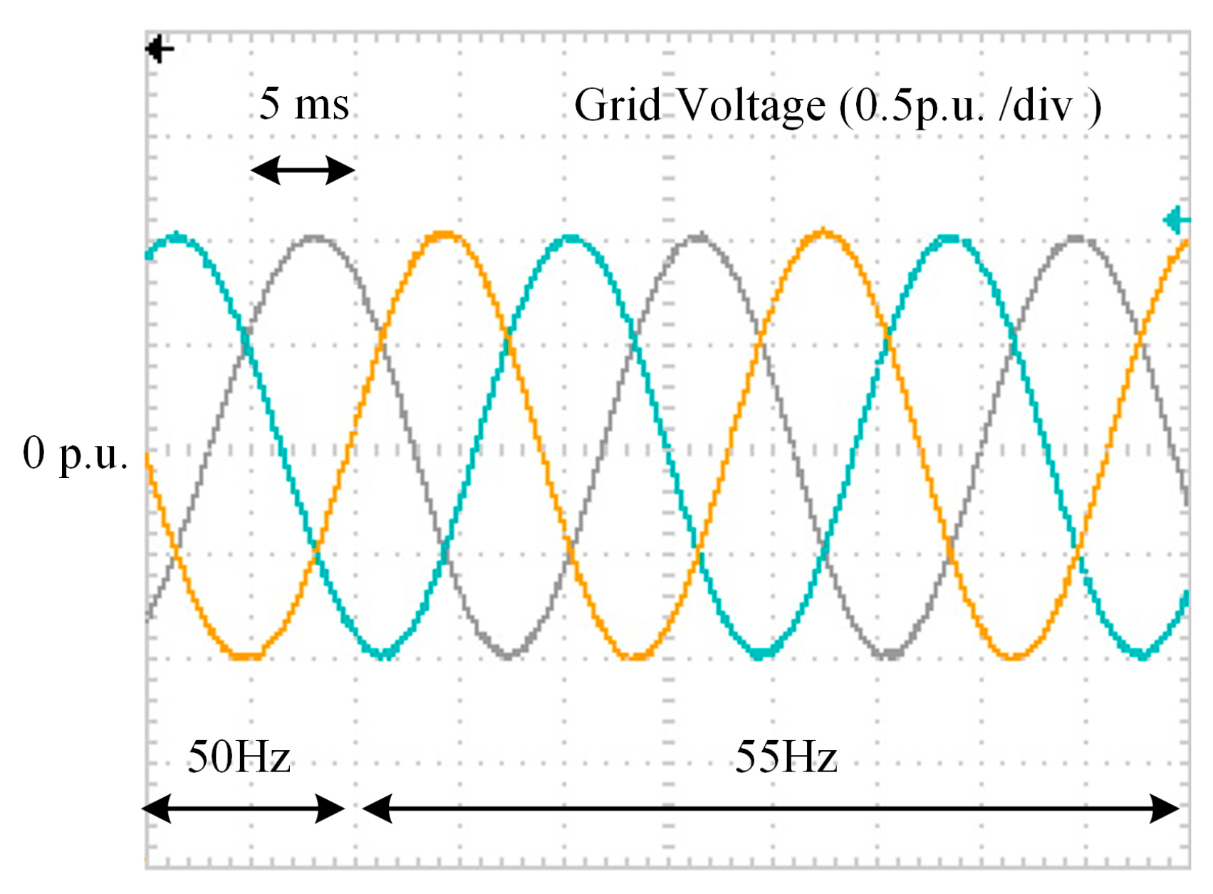
5.2. Test Case 2: Frequency Step Change
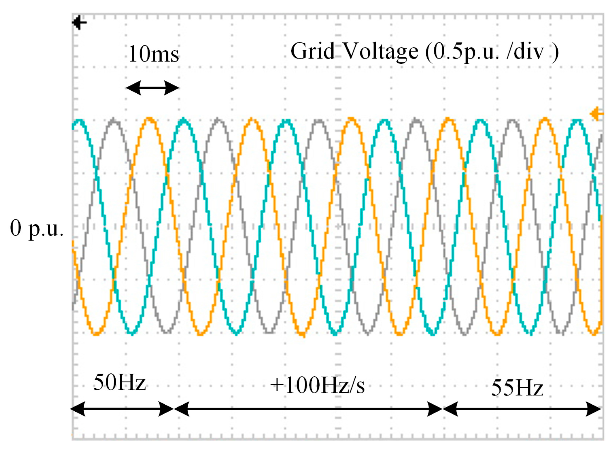
5.3. Test Case 3: Frequency Ramp Change
5.4. Test Case 4: Unbalanced and Distorted Grid Voltages
6. Conclusions
Author Contributions
Funding
Acknowledgments
Conflicts of Interest
Nomenclature
| vabc | Three-phase grid voltage |
| vd, vq | The d-q-axis voltage components after Park transformation |
| vα, vβ | The α-β-axis components of grid voltage after Clarke transformation |
| The α-β-axis components after prefiltering stage | |
| The d-q-axis voltage components after filtering processing | |
| vdm, vqm | The d-q-axis voltage components after MDSC |
| ωn | The fundamental nominal angular frequency of grid voltage |
| Δωg | The error of estimated angular frequency of grid voltage |
| The estimated angular frequency of grid voltage | |
| The angular phase of input grid voltage | |
| The estimated phase of grid voltage | |
| The phase-tracking error | |
| Tω | The window length of MAF |
| The value of phase jump | |
| k | The only control parameter in the proposed PLL |
References
- Kunjumuhammed, L.; Pal, B.C.; Gupta, R.; Dyke, K.J. Stability analysis of a PMSG-based large offshore wind farm connected to a VSC-HVDC. IEEE Trans. Energy Convers. 2017, 32, 1166–1176. [Google Scholar] [CrossRef]
- Zhang, X.; Shi, D.; Wang, Z.; Zeng, B.; Wang, X.; Tomsovic, K.; Jin, Y. Optimal allocation of series FACTS devices under high penetration of wind power within a market environment. IEEE Trans. Power Syst. 2018, 33, 6206–6217. [Google Scholar] [CrossRef]
- Zheng, Y.; Zhao, J.; Song, Y.; Luo, F.; Meng, K.; Qiu, J.; Hill, D.J. Optimal operation of battery energy storage system considering distribution system uncertainty. IEEE Trans. Energy Convers. 2018, 9, 1051–1060. [Google Scholar] [CrossRef]
- Mahmud, M.A.; Hossain, M.J.; Pota, H.R.; Roy, N.K. Robust nonlinear controller design for three-phase grid-connected photovoltaic systems under structured uncertainties. IEEE Trans. Power Del. 2014, 29, 1221–1230. [Google Scholar] [CrossRef]
- Chowdhury, M.A.; Shafiullah, G.M. SSR mitigation of series-compensated DFIG wind farms by a nonlinear damping controller using partial feedback linearization. IEEE Trans. Power Syst. 2018, 33, 2528–2538. [Google Scholar] [CrossRef]
- Vanfretti, L.; Baudette, M.; Domínguez-García, J.L.; Almas, M.S.; White, A.; Gjerde, J.O. A phasor measurement unit based fast real-time oscillation detection application for monitoring wind-farm-to-grid sub-synchronous dynamics. Electr. Mach. Power Syst. 2015, 44, 123–134. [Google Scholar] [CrossRef]
- Liu, H.; Xie, X.; Zhang, C.; Li, Y.; Liu, H.; Hu, Y. Quantitative SSR analysis of series-compensated DFIG-based wind farms using aggregated RLC circuit model. IEEE Trans. Power Syst. 2015, 30, 2772–2779. [Google Scholar] [CrossRef]
- Liu, H.; Xie, X.; Liu, W. An oscillatory stability criterion based on the unified dq-frame impedance network model for power systems with high-penetration renewables. IEEE Trans. Power Syst. 2018, 33, 3472–3485. [Google Scholar] [CrossRef]
- Golestan, S.; Guerrero, J.M.; Vidal, A.; Yepes, A.G.; Doval-Gandoy, J.; Freijedo, F.D. Small-signal modeling, stability analysis and design optimization of single-phase delay-based PLLs. IEEE Trans. Power Electron. 2016, 31, 3517–3527. [Google Scholar] [CrossRef]
- Hui, N.; Wang, D.; Li, Y. An efficient hybrid filter-based phase-locked loop under adverse grid conditions. Energies 2018, 11, 703. [Google Scholar] [CrossRef]
- Li, Y.; Yang, J.; Wang, H.; Ge, W.; Ma, Y. A hybrid filtering technique-based PLL targeting fast and robust tracking performance under distorted grid conditions. Energies 2018, 11, 973. [Google Scholar] [CrossRef]
- Li, Y.; Yang, J.; Wang, H.; Ge, W.; Ma, Y. Leveraging hybrid filter for improving quasi-type-1 phase locked loop targeting fast transient response. Energies 2018, 11, 2472. [Google Scholar] [CrossRef]
- Kulkarni, A.; John, V. Analysis of bandwidth-unit vector distortion trade off in PLL during abnormal grid conditions. IEEE Trans. Ind. Electron. 2013, 60, 5820–5829. [Google Scholar] [CrossRef]
- Batista, Y.N.; De Souza, H.E.P.; Neves, F.A.S.; Filho, R.F.D.; Bradaschia, F. Variable-structure generalized delayed signal cancellation PLL to improve convergence time. IEEE Trans. Ind. Electron. 2015, 62, 7146–7150. [Google Scholar] [CrossRef]
- Rodriguez, P.; Luna, A.; Munoz-Aguilar, R.S.; Etxeberria-Otadui, I.; Teodorescu, R.; Blaabjerg, F. A stationary reference frame grid synchronization system for three-phase grid-connected power converters under adverse grid conditions. IEEE Trans. Power Electron. 2012, 27, 99–112. [Google Scholar] [CrossRef]
- Burgos-Mellado, C.; Costabeber, A.; Sumner, M.; Cárdenas-Dobson, R.; Sáez, D. Small-signal modeling and stability assessment of phase-locked loops in weak grids. Energies 2019, 12, 1227. [Google Scholar] [CrossRef]
- Yang, L.; Chen, Y.; Wang, H.; Luo, A.; Huai, K. Oscillation suppression method by two notch filter for parallel inverters under weak grid conditions. Energies 2018, 11, 3441. [Google Scholar] [CrossRef]
- Li, M.; Zhang, X.; Zhao, W. A novel stability improvement strategy for multi-inverter system in a weak grid utilizing dual-model control. Energies 2018, 12, 2144. [Google Scholar] [CrossRef]
- E.On Netz. Grid Code-High and Extra High Voltage; Netz Gmbh: Bayreuth, Germany, 2006; Available online: http://www.pvupscale.org/IMG/pdf/D4_2_DE_annex_A-3_EON_HV_grid__connection_requirements_ENENARHS2006de.pdf (accessed on 16 April 2018).
- Ministerio de Industria, Turismo y Comercio. Requisitos de Respuesta Frente a Huecos de Tension de las Instalaciones Eolicas; Comisión Nacional de Energía: Madrid, Spain, 2006.
- IEEE Std. IEEE Standard for Interconnecting Distributed Resources with Electric Power Systems; IEEE: New York, NY, USA, 2003. [Google Scholar]
- National Grid Electricity Transmission. The Grid Code: Revision 31; National Grid Electricity Transmission: Warwick, UK, 2008. [Google Scholar]
- Li, Y.; Wang, D.; Han, W.; Tan, S.; Guo, X. Performance improvement of quasi-type-1 PLL by using a complex notch filter. IEEE Access 2016, 4, 6272–6282. [Google Scholar] [CrossRef]
- Golestan, S.; Guerrero, J.M.; Vidal, A.; Yepes, A.G.; Doval-Gandoy, J. PLL with MAF-based prefiltering stage: Small-signal modeling and performance enhancement. IEEE Trans. Power Electron. 2016, 31, 4013–4019. [Google Scholar] [CrossRef]
- Rodriguez, P.; Teodorescu, R.; Candela, I.; Timbus, A.V.; Liserre, M.; Blaabjerg, F. New positive-sequence voltage detector for grid synchronization of power converters under faulty grid conditions. In Proceedings of the IEEE Power Electronics Specialists Conference, Jeju, Korea, 18–22 June 2006; pp. 1–7. [Google Scholar]
- Guo, X.; Wu, W.; Chen, Z. Multiple-complex coefficient-filter-based phase-locked loop and synchronization technique for three-phase grid-interfaced converters in distributed utility networks. IEEE Trans. Ind. Electron. 2011, 58, 1194–1204. [Google Scholar] [CrossRef]
- Xiao, P.; Corzine, K.A.; Venayagamoorthy, G.K. Multiple reference frame-based control of three-phase PWM boost rectifiers under unbalanced and distorted input conditions. IEEE Trans. Power Electron. 2008, 23, 2006–2017. [Google Scholar] [CrossRef]
- Rodríguez, P.; Pou, J.; Bergas, J.; Candela, J.I.; Burgos, R.P.; Boroyevich, D. Decoupled double synchronous reference frame PLL for power converters control. IEEE Trans. Power Electron. 2007, 22, 584–592. [Google Scholar] [CrossRef]
- Golestan, S.; Ramezani, M.; Guerrero, J.M.; Monfared, M. Dq-frame cascaded delay signal cancellation-based pll: Analysis, design, and comparison with moving average filter-based PLL. IEEE Trans. Power Electron. 2015, 3, 1618–1632. [Google Scholar] [CrossRef]
- Wang, Y.F.; Li, Y.W. Grid synchronization pll based on cascaded delay signal cancellation. IEEE Trans. Power Electron. 2011, 26, 1987–1997. [Google Scholar] [CrossRef]
- Wang, Y.F.; Li, Y.W. Three-phase cascaded delay signal cancellation pll for fast selective harmonic detection. IEEE Trans. Ind. Electron. 2013, 60, 1452–1463. [Google Scholar] [CrossRef]
- Rani, B.I.; Aravind, C.K.; Ilango, G.S.; Nagamani, C. A three phase PLL with a dynamic feed forward frequency estimator for synchronization of grid connected converters under wide frequency variations. Int. J. Electr. Power Energy Syst. 2012, 41, 63–70. [Google Scholar] [CrossRef]
- Geng, H.; Sun, J.; Xiao, S.; Yang, G. Modeling and implementation of an all digital phase-locked-loop for grid-voltage phase detection. IEEE Trans. Ind. Inf. 2013, 9, 772–780. [Google Scholar] [CrossRef]
- Golestan, S.; Ramezani, M.; Guerrero, J. An analysis of the PLLs with secondary control path. IEEE Trans. Ind. Electron. 2014, 61, 4824–4828. [Google Scholar] [CrossRef]
- Golestan, S.; Freijedo, F.D.; Vidal, A.; Guerrero, J.M.; Doval-Gandoy, J. A quasi-type-1 phase-locked loop structure. IEEE Trans. Power Electron. 2014, 29, 6264–6270. [Google Scholar] [CrossRef]
- Golestan, S.; Guerrero, J.M.; Vasquez, J.C. Hybrid adaptive/nonadaptive delay signal cancellation-based phase-locked loop. IEEE Trans. Ind. Electron. 2017, 64, 470–479. [Google Scholar] [CrossRef]
- Golestan, S.; Freijedo, F.D.; Vidal, A.; Yepes, A.G.; Guerrero, J.M.; Doval-Gandoy, J. An efficient implementation of generalized delayed signal cancellation PLL. IEEE Trans. Power Electron. 2016, 31, 1085–1094. [Google Scholar] [CrossRef]
- Golestan, S.; Ramezani, M.; Guerrero, J.M.; Freijedo, F.D.; Monfared, M. Moving average filter based phase-locked loop: Performance analysis and design guidelines. IEEE Trans. Power Electron. 2014, 29, 2750–2763. [Google Scholar] [CrossRef]


| Harmonic Order | … | +1 | −1 | −5 | +7 | −11 | +13 | … |
|---|---|---|---|---|---|---|---|---|
| αβ-frame (Hz) | … | 50 | −50 | −250 | 350 | −550 | 650 | … |
| Harmonic order | … | 0 | −2 | −6 | +6 | −12 | +12 | … |
| dq-frame (Hz) | … | 0 | −100 | −300 | 300 | −600 | 600 | … |
| Voltage Component (in αβ-frame) | Amplitude (p.u.) |
|---|---|
| Fundamental positive sequence (+1st order) | 1 |
| Fundamental negative sequence (−1st order) | 0.1 |
| 5th harmonic negative sequence (−5th order) | 0.1 |
| 7th harmonic positive sequence (+7th order) | 0.05 |
| 11th harmonic negative sequence (−11th order) | 0.05 |
| 13th harmonic positive sequence (+13th order) | 0.05 |
© 2019 by the authors. Licensee MDPI, Basel, Switzerland. This article is an open access article distributed under the terms and conditions of the Creative Commons Attribution (CC BY) license (http://creativecommons.org/licenses/by/4.0/).
Share and Cite
Li, T.; Li, Y.; Yang, J.; Ge, W.; Hu, B. A Modified DSC-Based Grid Synchronization Method for a High Renewable Penetrated Power System Under Distorted Voltage Conditions. Energies 2019, 12, 4040. https://doi.org/10.3390/en12214040
Li T, Li Y, Yang J, Ge W, Hu B. A Modified DSC-Based Grid Synchronization Method for a High Renewable Penetrated Power System Under Distorted Voltage Conditions. Energies. 2019; 12(21):4040. https://doi.org/10.3390/en12214040
Chicago/Turabian StyleLi, Tie, Yunlu Li, Junyou Yang, Weichun Ge, and Bo Hu. 2019. "A Modified DSC-Based Grid Synchronization Method for a High Renewable Penetrated Power System Under Distorted Voltage Conditions" Energies 12, no. 21: 4040. https://doi.org/10.3390/en12214040
APA StyleLi, T., Li, Y., Yang, J., Ge, W., & Hu, B. (2019). A Modified DSC-Based Grid Synchronization Method for a High Renewable Penetrated Power System Under Distorted Voltage Conditions. Energies, 12(21), 4040. https://doi.org/10.3390/en12214040