Accuracy Improvement Method of Energy Storage Utilization with DC Voltage Estimation in Large-Scale Photovoltaic Power Plants


 ,
, 

Abstract
1. Introduction
2. System Configuration
2.1. General Objective
2.2. Conceptual Design
2.3. Alternating Current/Direct Current (AC/DC) Hybrid System
2.4. DC Network
2.4.1. Generation System
2.4.2. Storage System
3. DC Flow Analysis
4. Simulation
4.1. Simulation Design
4.2. Simulation Results
5. Conclusions
Author Contributions
Funding
Conflicts of Interest
Nomenclature
| gn | Equivalent admittance of nth module |
| guno | Admittance of positive side DC cable between nth module and collector |
| gdno | Admittance of negative side DC cable between nth module and ground |
| gdc-dc | Equivalent admittance about DC/DC convertor for ESS |
| gESS | Equivalent admittance of ESS module |
| G | Solar irradiation (W/m2) |
| IPV | PV current in single diode model |
| Ir | Reverse saturation current of PV |
| Isc | Short circuit current of PV |
| Io | Output current in single diode model |
| RP | Shunt resistance of PV |
| RS | Series resistance of PV |
| Vun | Upper-side voltage of nth module |
| Vdn | Lower-side voltage of nth module |
| Vdc | Collector voltage |
| VESS | Induced ESS voltage |
References
- Rakhshani, E.; Rouzbehi, K.; Sánchez, A.J.; Tobar, A.C.; Pouresmaeil, E. Integration of Large Scale PV-Based Generation into Power Systems: A Survey. Energies 2019, 12, 1425. [Google Scholar] [CrossRef]
- Biggest Solar Power Plants. Mechanical, Electrical and Electronics Engineers. Available online: https://meee-services.com/biggest-solar-power-plants (accessed on 30 August 2018).
- Su, M.; Luo, C.; Hou, X.; Yuan, W.; Liu, Z.; Han, H.; Guerrero, J.M. A Communication-Free Decentralized Control for Grid-Connected Cascaded PV Inverters. Energies 2018, 11, 1375. [Google Scholar] [CrossRef]
- Osório, G.J.; Shafie-khah, M.; Lujano-Rojas, J.M.; Catalão, J.P. Scheduling Model for Renewable Energy Sources Integration in an Insular Power System. Energies 2018, 11, 144. [Google Scholar] [CrossRef]
- Subramani, G.; Ramachandaramurthy, V.K.; Padmanaban, S.; Mihet-Popa, L.; Blaabjerg, F.; Guerrero, J.M. Grid-tied photovoltaic and battery storage systems with Malaysian electricity tariff—A review on maximum demand shaving. Energies 2017, 10, 1884. [Google Scholar] [CrossRef]
- Zeng, Z.; Yang, H.; Zhao, R.; Cheng, C. Topologies and control strategies of multi-functional grid-connected inverters for power quality enhancement: A comprehensive review. Renew. Sustain. Energy Rev. 2013, 24, 223–270. [Google Scholar] [CrossRef]
- Miao, L.; Wen, J.; Xie, H.; Yue, C.; Lee, W. Coordinated control strategy of wind turbine generator and energy storage equipment for frequency support. IEEE Trans. Ind. Appl. 2015, 51, 2732–2742. [Google Scholar] [CrossRef]
- Bird, L.; Cochran, J.; Wang, X. Wind and Solar Energy Curtailment: Experience and Practices in the United States; NREL: Golden, CO, USA, 2014. [Google Scholar]
- Chen, P.; Thiringer, T. Analysis of Energy Curtailment and Capacity Over installation to Maximize Wind Turbine Profit Considering Electricity Price—Wind Correlation. IEEE Trans. Sustain. Energy 2017, 8, 1406–1414. [Google Scholar] [CrossRef]
- Saez-de-Ibarra, A.; Milo, A.; Gaztañaga, H.; Debusschere, V.; Bacha, S. Co-Optimization of Storage System Sizing and Control Strategy for Intelligent Photovoltaic Power Plants Market Integration. IEEE Trans. Sustain. Energy 2016, 7, 1749–1761. [Google Scholar] [CrossRef]
- Stimoniaris, D.; Tsiamitros, D.; Dialynas, E. Improved Energy Storage Management and PV-Active Power Control Infrastructure and Strategies for Microgrids. IEEE Trans. Power Syst. 2016, 31, 813–820. [Google Scholar] [CrossRef]
- Shi, G.; Zhang, J.; Cai, X.; Zhu, M. Decoupling control of series-connected DC wind turbines with energy storage system for offshore DC wind farm. In Proceedings of the IEEE 7th International Symposium on Power Electronics for Distributed Generation Systems (PEDG), Vancouver, BC, Canada, 27–30 June 2016. [Google Scholar]
- Vargas, L.S.; Bustos-Turu, G.; Larraín, F. Wind Power Curtailment and Energy Storage in Transmission Congestion Management Considering Power Plants Ramp Rates. IEEE Trans. Power Syst. 2015, 30, 2498–2506. [Google Scholar] [CrossRef]
- Knap, V.; Chaudhary, S.K.; Stroe, D.; Swierczynski, M.; Craciun, B.; Teodorescu, R. Sizing of an Energy Storage System for Grid Inertial Response and Primary Frequency Reserve. IEEE Trans. Power Syst. 2016, 31, 3447–3456. [Google Scholar] [CrossRef]
- Zhang, H.; Yue, D.; Xie, X. Robust Optimization for Dynamic Economic Dispatch under Wind Power Uncertainty with Different Levels of Uncertainty Budget. IEEE Access 2016, 4, 7633–7644. [Google Scholar] [CrossRef]
- Byungdoo, J.; Hyun, K.; Heechan, K.; Hansang, L. Development of a Novel Charging Algorithm for On-board ESS in DC Train through Weight Modification. J. Electr. Eng. Technol. 2014, 9, 1795–1804. [Google Scholar]
- Yang, J.; Fletcher, J.E.; O’Reilly, J. Multiterminal DC wind farm collection grid internal fault analysis and protection design. IEEE Trans. Power Del. 2010, 25, 2903–2912. [Google Scholar] [CrossRef]
- Kaipia, T.; Salonen, P.; Lassila, J.; Partanen, J. Possibilities of the low voltage DC distribution systems. In Proceedings of the NORDAC Conference, Stockholm, Sweden, 30 August–2 September 2006. [Google Scholar]
- Dzamarija, M.; Keane, A. Autonomous curtailment control in distributed generation planning. IEEE Trans. Smart Grid 2016, 7, 1337–1345. [Google Scholar] [CrossRef]
- Jung, S.; Yoon, Y.-T.; Jang, G. Adaptive Curtailment Plan with Energy Storage for AC/DC Combined Distribution Systems. Sustainability 2016, 8, 818. [Google Scholar] [CrossRef]
- Yazdani, A.; Dash, P.P. A Control Methodology and Characterization of Dynamics for a Photovoltaic (PV) System Interfaced with a Distribution Network. IEEE Trans. Power Deliv. 2009, 24, 1538–1551. [Google Scholar] [CrossRef]
- Cabrera-Tobar, A.; Bullich-Massagué, E.; Aragüés-Peñalba, M.; Gomis-Bellmunt, O. Topologies for large scale photovoltaic power plants. Renew. Sustain. Energy Rev. 2016, 59, 309–319. [Google Scholar] [CrossRef]
- Mansur, A.A.; Amin, M.R.; Islam, K.K. Performance Comparison of Mismatch Power Loss Minimization Techniques in Series-Parallel PV Array Configurations. Energies 2019, 12, 874. [Google Scholar] [CrossRef]
- Widén, J.; Wäckelgård, E.; Paatero, J.; Lund, P. Impacts of distributed photovoltaics on network voltages: Stochastic simulations of three Swedish low-voltage distribution grids. Electr. Power Syst. Res. 2010, 80, 1562–1571. [Google Scholar] [CrossRef]
- Paatero, J.V.; Lund, P.D. Effects of large-scale photovoltaic power integration on electricity distribution networks. Renew. Energy 2007, 32, 216–234. [Google Scholar] [CrossRef]
- Koutroulis, E.; Blaabjerg, F. A New Technique for Tracking the Global Maximum Power Point of PV Arrays Operating Under Partial-Shading Conditions. IEEE J. Photovolt. 2012, 2, 184–190. [Google Scholar] [CrossRef]
- Karanayil, B.; Ceballos, S.; Pou, J. Maximum Power Point Controller for Large Scale Photovoltaic Power Plants Using Central Inverters under Partial Shading Conditions. IEEE Trans. Power Electron. 2018, 34, 3098–3109. [Google Scholar] [CrossRef]
- Garces, A. A Linear Three-Phase Load Flow for Power Distribution Systems. IEEE Trans. Power Syst. 2016, 31, 827–828. [Google Scholar] [CrossRef]
- Karthikeyan, V.; Gupta, R. Multiple-Input Configuration of Isolated Bidirectional DC–DC Converter for Power Flow Control in Combinational Battery Storage. IEEE Trans. Ind. Inform. 2018, 14, 2–11. [Google Scholar] [CrossRef]
- Chew, B.S.H.; Xu, Y.; Wu, Q. Voltage Balancing for Bipolar DC Distribution Grids: A Power Flow Based Binary Integer Multi-Objective Optimization Approach. IEEE Trans. Power Syst. 2019, 34, 28–39. [Google Scholar] [CrossRef]
- Jabr, R.A.; Džafić, I. Solution of DC Railway Traction Power Flow Systems Including Limited Network Receptivity. IEEE Trans. Power Syst. 2018, 33, 962–969. [Google Scholar] [CrossRef]
- Jayalakshmi, N.S.; Gaonkar, D.N.; Adarsh, S.; Sunil, S. A control strategy for power management in a PV-battery hybrid system with MPPT. In Proceedings of the 2016 IEEE 1st International Conference on Power Electronics, Intelligent Control and Energy Systems (ICPEICES), Delhi, India, 4–6 July 2016; pp. 1–6. [Google Scholar]
- Ardashir, J.F.; Sabahi, M.; Hosseini, S.H.; Blaabjerg, F.; Babaei, E.; Gharehpetian, G.B. A Single-Phase Transformerless Inverter with Charge Pump Circuit Concept for Grid-Tied PV Applications. IEEE Trans. Ind. Electron. 2017, 64, 5403–5415. [Google Scholar] [CrossRef]
- Zhang, D.; Li, J.; Hui, D. Coordinated control for voltage regulation of distribution network voltage regulation by distributed energy storage systems. Prot. Control Mod. Power Syst. 2018, 3, 3. [Google Scholar] [CrossRef]


| Specific Data | Value | Unit |
|---|---|---|
| Rated AC voltage | 22.9 | kV |
| Rated DC voltage | 500 | V |
| Distance between each module | 0.5 | Meter |
| Number of load | 3 | |
| Rated energy of ESS | 200 | kWh |
| Rated power of ESS | 200 | kW |
| Rated power of PV system | 1200 | kW |
| PI-line distance | 500 | Meter |
| Substation voltage (HV) | 154 | kV |
| Short-circuit ratio of utility grid | 15 | |
| X/R ratio of utility grid | 15 |
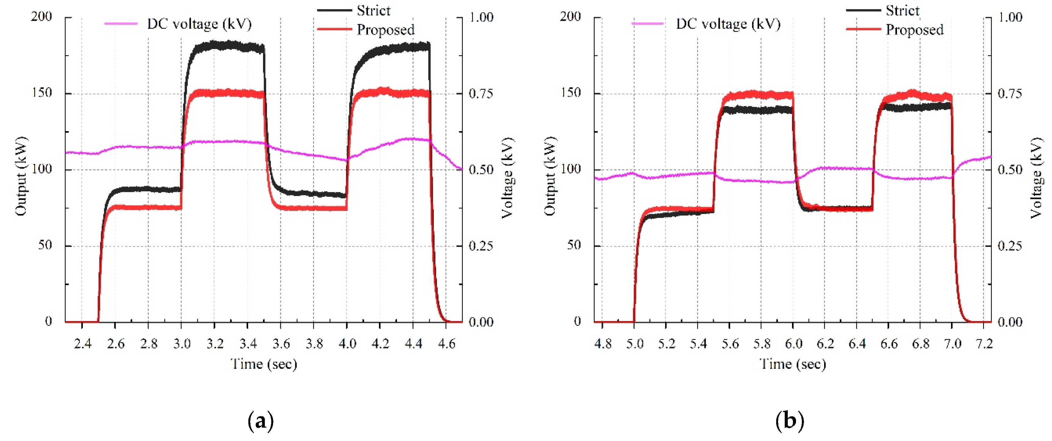
| Imposed Control Method | Strict Voltage Control Method, Proposed Control Method |
|---|---|
| Simulation time | 10 s |
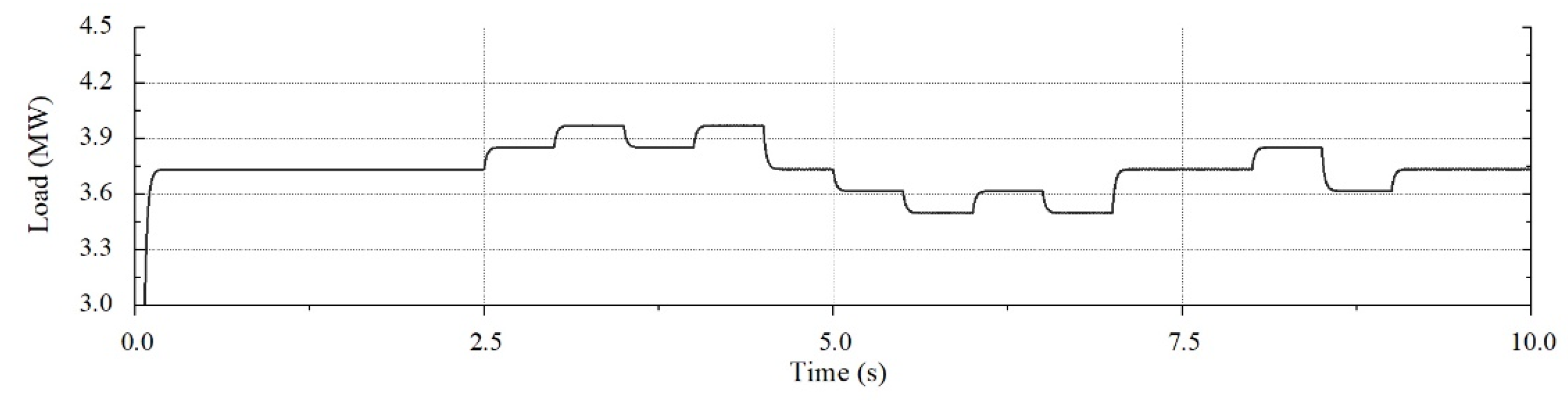
| Base load condition (Real power) | Load 1: 900 kW Load 2: 1500 kW Load 3: 1380 kW |
| Load increase sections (Load 3) | 2.5–3, 3.5–4, 8–8.5 s (75 kW) 3–3.5, 4–4.5 s (150 kW) |
| Load decrease sections (Load 3) | 5–5.5, 6–6.5, 8.5–9 s (75 kW) 5.5–6, 6.5–7 s (150 kW) |
| Control | ESS Mode | Demanded Quantity (Wh) | Accomplished Quantity (Wh) | Gap(Wh) | Error (%) |
|---|---|---|---|---|---|
| Strict voltage | Charging | 145.83 | 136.304 | 9.526 | 6.53 |
| Discharging | 145.83 | 167.877 | 22.047 | 15.12 | |
| Proposed | Charging | 145.83 | 140.912 | 4.918 | 3.37 |
| Discharging | 145.83 | 143.834 | 1.996 | 1.37 |
© 2019 by the authors. Licensee MDPI, Basel, Switzerland. This article is an open access article distributed under the terms and conditions of the Creative Commons Attribution (CC BY) license (http://creativecommons.org/licenses/by/4.0/).
Share and Cite
Yoo, Y.; Jang, G.; Kim, J.-H.; Nam, I.; Yoon, M.; Jung, S. Accuracy Improvement Method of Energy Storage Utilization with DC Voltage Estimation in Large-Scale Photovoltaic Power Plants. Energies 2019, 12, 3907. https://doi.org/10.3390/en12203907
Yoo Y, Jang G, Kim J-H, Nam I, Yoon M, Jung S. Accuracy Improvement Method of Energy Storage Utilization with DC Voltage Estimation in Large-Scale Photovoltaic Power Plants. Energies. 2019; 12(20):3907. https://doi.org/10.3390/en12203907
Chicago/Turabian StyleYoo, Yeuntae, Gilsoo Jang, Jeong-Hwan Kim, Iseul Nam, Minhan Yoon, and Seungmin Jung. 2019. "Accuracy Improvement Method of Energy Storage Utilization with DC Voltage Estimation in Large-Scale Photovoltaic Power Plants" Energies 12, no. 20: 3907. https://doi.org/10.3390/en12203907
APA StyleYoo, Y., Jang, G., Kim, J.-H., Nam, I., Yoon, M., & Jung, S. (2019). Accuracy Improvement Method of Energy Storage Utilization with DC Voltage Estimation in Large-Scale Photovoltaic Power Plants. Energies, 12(20), 3907. https://doi.org/10.3390/en12203907