Abstract
The quality of power and current control are the greatest challenges of grid-connected wind farms during abnormal conditions. The negative- and positive-sequence components of the grid currents may be injected into a wind generation system during grid faults, which can affect the power stability and damage the wind system. The proposed work assures a low-voltage ride through capability of doubly-fed induction generator- based wind turbines under the grid voltage sag. A new technique to protect the wind system and to recompense the reactive power during failures of the utility grid according to the Spanish grid code is proposed. The control design is implemented to the power converters, and the grid current regulation is developed by using proportional-resonant regulators in a stationary two-phase (αβ) reference frame. The control performance is significantly validated by applying the real-time simulation for the rotor-side converter and the hardware in the loop simulation technique for the experiment of the generator’s grid-side converter control.
1. Introduction
Nowadays, the recent energy production faces an increasing awareness concerning the conventional power generation impact on the environment since it is infected by CO2 emission [1]. Such a problematic requires new alternative technologies to create energy in environment-friendly ways and, considering the increasing demand for global energy, society has a greater environmental responsibility to develop green technologies. Under the electrical power market expansion, the most rapidly developed sector is wind energy [2].
The whole wind turbine system adopted on a doubly-fed induction generator (DFIG) comprises different components [3], which effectively contribute in the power conversion from the wind kinetic energy to the electrical power transferred to a utility grid [4,5]. The generator model for a grid-connected DFIG used in wind turbines [6] is presented in Figure 1. Since the turbine is related to the rotor by a gearbox, DFIG affords a variable speed because of the power converters which are used to control the rotor current [7,8]. For coupling the converter by slip rings to the rotor, a wound rotor induction generator is used. Conditioned by the converter dimension, the stated concept supports an extended variable speed ranging from around −30% to approximately 30% throughout a synchronous speed [9]. More than that, the converter controls reactive power and stabilizes the utility grid connection. The power converter of a DFIG connected to the utility grid can be designed for 25–30% of the entire generated electrical power [10,11], since both power converters transmit only the rotor power which depends on the slip [11]. Consequently, the concept is very captivating, economically speaking, against turbines with the full-scale converter.
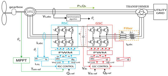
Figure 1.
DFIG system connected to a utility grid.
On the one hand, the wind turbines integration into the grid places the ability of power control, which implies that wind turbines need an output-adjusting power to contribute to the dispatch balance (production/consumption) [4,5]. On the other hand, low-voltage ride through (LVRT) and reactive power injection from the DFIG system are important for grid codes [12,13,14,15]. Thereby, the grid-connected wind turbine controllability according to grid compatibility has a great impact on future development [16,17].
Perturbations in the utility grid, even far away from turbines zones, may create a disturbance at the wind system grid connection point [18,19]. The aforementioned perturbation causes an over-current on stator and rotor windings and also increases the DC-link voltage between power converters to unacceptable values [20,21], which can damage the system if no protection is allowed. Besides, it also produces the turbine over-speeding, affecting system safety [22]. For this reason, there are several research works proposing solutions to this fact.
In the functional command of the DFIG, vector controls with the orientation of stator voltage or stator flux have been commonly used [23,24,25]. By using this type of control strategy, proportional-integral (PI) regulators are classically aiming to regulate the power transfer into the utility grid. However, when a voltage sag takes place, the PI controller seems to be overloaded rapidly. In addition, the system regularization is tough to realize. Therefore, the DFIG loses command ability. In order to manage the traditional vector control weakness, different approaches were proposed to improve strategies to reach the LVRT.
According to the obtained results for traditional DFIG vector controllers [26,27,28], the generator still operates within a specific range during a grid fault. Nevertheless, the proper dynamic response of two state variables, such as rotor voltage and rotor current, cannot be assured. This technique can only be used under symmetrical grid faults.
Some research papers have investigated the control and behaviour of DFIG grid-connected converters under abnormal operation of the grid voltage. In [29,30], two regulators were used after the positive- and negative-sequence components (P–N SCs) separation for a current loop’s regulation, which can increase the delay and errors of the dynamic response and affect the system stability during this process. The same configurations were adopted in [31,32], that is, under unbalanced grid conditions, a main regulator was employed in a positive-sequence synchronous reference frame and a secondary regulator was employed in a negative-sequence synchronous reference frame. In References [33,34,35] a PI-R current regulator was applied in order to eliminate multiple harmonics in grid converter systems during grid voltage distortion but non-linear transformations abc → dq is mandatory. The operation of DFIG under the abnormal operation of the utility grid was studied in [36,37,38] and many possibilities for reducing oscillations at twice the fundamental frequency have been investigated. Nevertheless, a rotor-side converter (RSC) was examined in this paper and two current regulators were implemented for the P–N SCs. Furthermore, because of the RSC limited control, it is difficult to obtain a simultaneous rejection of power oscillations and therefore, an improved control method was used to deal with unbalanced grid voltages. Unlike the described techniques, in this paper, a new current reference calculation process was proposed, by injecting sinusoidal currents even under abnormal grid conditions using Clark’s transformation, which converts a three-phase system (abc) into a two-phase orthogonal system (αβ) and allows proportional-resonant (PR) regulators to track and discard sinusoidal variables. The use of the stationary reference frame is possible with the proposed algorithm, in order to decrease the computational difficulty and avoid the application of the synchronous reference frame. Thus, the non-linear transformation (abc → dq) used with PI-R regulators is changed by the linear abc → αβ transformation using the PR controllers [39,40]. Moreover, as explained in Section 3, PR regulators can control the two sequences generated during grid voltage faults.
This work explores an application of the PR regulators on a DFIG’s grid-side converter (GSC), mainly in their capability for the compensation of reactive power, grid current limitation and the stabilization of active power during a grid fault.
The work novelty can be observed in the proposed LVRT algorithm presented in Section 3 according to the IEC 61400-21 [41] and the Spanish grid code, generating the P–N SCs of the grid currents with the implementation of the PR regulators on the DFIG’s GSC in the αβ components of the 3-phase inverter currents. This feature will have the capability for the compensation of reactive power and the grid current limitation during a grid fault according to the Spanish grid code.
The paper is structured as follow; firstly, the main control of the DFIG for the RSC and an explanation of the GSC control using the PR controller are presented in Section 2. Section 3 presents the Spanish grid code besides the algorithm presented in this paper. Section 4 presents the digital real-time simulations (DRTS) using the dSPACE ControlDesk environment [42]. In Section 5, some experiments are performed using the controller hardware-in-the-loop (CHIL) technique to validate the proposed strategy for the Fault Ride-Through (FRT) capability. Subsequently, the conclusion is stated in Section 6.
2. DFIG Control
The electrical part of DFIG consists of 3-phase stator windings which are connected to a 3-phase windings transformer, while the 3-phase machine’s rotor windings are directly excited by two power converters, RSC and GSC, The grid side of the power converters delivers the rotor power to the grid via the 3-winding transformer. The schematic block of the DFIG connected to the utility grid is shown in Figure 1. The rotor voltages control makes it possible to manage the magnetic field inside the machine.
The equivalent electrical circuit of the rotor and the stator windings in an arbitrary reference frame is represented in Figure 2. According to Figure 2, stator and rotor fluxes (φ) are expressed as Equations (1) and (2):
where and are the rotor and stator inductances, respectively, and is the mutual inductance; Is and Ir are the stator and the rotor currents, respectively. Additionally, according to Figure 2, the stator and the rotor voltage can be written as:
where and are the rotor and the stator resistances, respectively, is the stator pulsation and is the rotor pulsation.
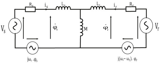
Figure 2.
The DFIG’s equivalent electrical circuit.
Based on Equations (1) and (2), the rotor flux and the stator current can be written as:
where .
Then, by substituting Equation (4) into Equation (3), the expression of in the arbitrary rotating reference is:
The purpose of a reference change is to make the machine equations easier to use. In this study, the Park’s transformation (two d-q orthogonal axes in the rotating synchronous reference frame) is used for RSC control to apply the vector control technique and Clarke’s transformation (two αβ orthogonal axes in the stationary reference frame) for GSC control. This model is obtained after a three-phase (A, B and C) virtual transformation into an equivalent two-phase machine as represented in Figure 3 [43].
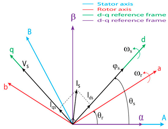
Figure 3.
Park’s and Clarke’s transformations of the DFIG system.
2.1. DFIG Control Strategy
After the Park’s transformation application, and with a reference linked to the rotating field, the expressions of the stator and rotor voltages along the d-q axes are:
The matrix system of the flux can be written as:
The expression of DFIG’s electromagnetic torque is expressed as follows:
The transferred active and reactive powers from DFIG (through the stator and rotor windings) to the utility grid are written as follows [44]:
The stator flux has been oriented with the d-axis to apply the vector control technique. The choice of this reference makes the generated reactive power and the electromagnetic torque depend on the d- and q- components of rotor currents and , respectively. Thus, these stator powers can be controlled independently of each other.
Tow control blocks are implemented on the RSC, i.e., the maximum power extraction from the wind and the vector control block using the PI regulators.
In the following, the maximum power point tracking (MPPT) is briefly explained [45]. The mechanical torque Tm, which is taken by the turbine, is given as:
where: is the air density, is the power coefficient, is the wind velocity and is the turbine radius.
In order to pull out the utmost power by the wind turbine at different wind speeds, Figure 4 represents the trajectory of an MPPT curve, which can be expressed in terms of the mechanical torque Tm,MPPT by the following equation:
where is the optimal coefficient torque and is the mecanical rotation speed.
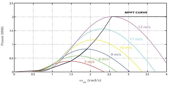
Figure 4.
Power curve of the DFIG system with MPPT.
After the stator flux orientation along d-axis and neglection of the per phase stator resistance [9], the d-component of the stator flux is written as:
where is considered constant (its derivative is zero) and equal to the stator flux vector modulus; and can be written as:
The stator voltage in Equation (7) becomes:
The electromagnetic torque in Equation (10) is written as:
Then, Equation (10) of the stator fluxes according to Equation (20) becomes:
Finally, the reactive power and active power in Equations (13) and (14) are written as follows:
The generator is used to transform the mechanical power into AC power, and then the RSC and GSC are used to control and convert that power into a grid connection. By using the GSC, the incoming AC power is injected into the utility grid with its synchronized frequency and phase for power factor control. The configuration of the DFIG’s RSC control blocks is shown in Figure 5.
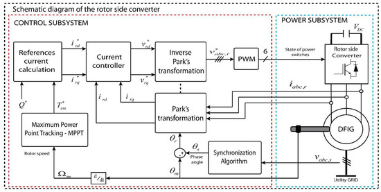
Figure 5.
Schematic diagram of the RSC.
2.2. Grid-Side Converter Regulation Using PR regulators
The second converter in DFIG is the GSC which controls the balance of power between the DFIG and the utility grid.
The GSC is able to regulate the DC voltage in order to generate the reference of active power by using a PI regulator [46] and also to regulate the injected reactive power into the utility grid. The latter is achieved by regulating properly the P–N SCs of the grid currents to deal with the grid voltage disturbance conditions and the power oscillations furnished by the RSC to the DC-link. The P–N SCs of the faulty utility grid must be calculated from the measured three-phase voltages.
The PR current regulators in the stationary reference frame are applied in this section [47]. This kind of regulators commonly contains a PR regulator plus a resonant filter tuned to the fundamental frequency in order to reach a zero steady-state error when sinusoidal signals are controlled. A detailed study of the PR regulator was presented in [48] and hence, only a short explanation is provided in this paper. The transfer function of the PR regulator is expressed as:
where is the proportional constant, is the integral constant of the regulator, is the cutoff frequency and is the resonance frequency.
The grid current references expressions in the stationary reference frame ( and ) are written according to the active and reactive current components ( and ) and ( and ), respectively [49]:
where
Figure 6 describes the GSC block diagram control using the PR regulators; meanwhile, the P–N SCs of grid voltage are calculated from the measured grid voltage [50]. The four grid voltage components (, , and ) generated by the P–N SCs detector together with and are used to compute the two grid currents references in the stationary reference frame ( and ) with the current references calculation module. The two currents references and are compared to the measured signals, and the difference is supplied to the PR regulators. The outputs of these regulators are the inverter voltage signals in the stationary reference frame, and hence, the inverse Clarke’s transformation is applied to these variables in order to feed the pulse width modulation (PWM). The outputs of PWM are the switching signals for the three-phase inverter.
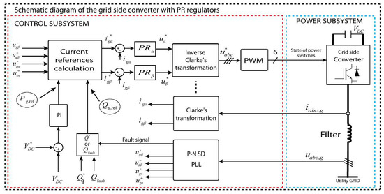
Figure 6.
Schematic diagram GSC control.
The P–N SCs block is represented in Figure 7. The P–N SCs block is used to compute the grid voltage positive and negative sequences ( and ). After Clark’s transformation, the positive sequences are used to calculate the voltage sag in order to generate the fault signal based on Equation (32). The main outcomes of this paper are the generation of the P–N SCs of the grid currents in an easy way by applying Equations (27)–(31) to exert a constant active power control, which will decrease the oscillations amplitude at twice the fundamental frequency in the DC voltage, protecting the link capacitor for its potential destruction.
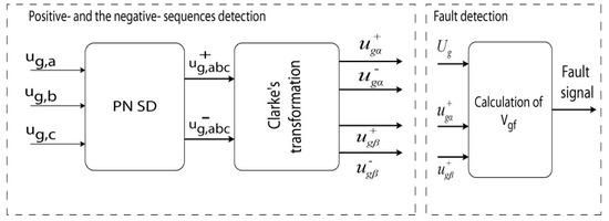
Figure 7.
P–N SCs block.
3. Grid Code (Output Current Limitation)
The wind system must respect the LVRT requirements and must stay connected to the grid when severe faults occur, according to the grid code used. In addition, the grid code imposes the necessity to inject some reactive power for specific levels in the depth of the voltage dips [51] and to limit the current amplitude near its nominal value in order to avoid the generator disconnection from the grid. Figure 8a presents the LVRT requirements according to IEC 61400-21 [41]; Figure 8b presents the Spanish grid code requirements for the reactive power during grid faults [49].
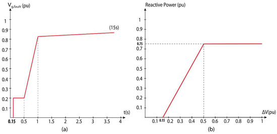
Figure 8.
(a) LVRT requirements according to IEC 61400-21 and (b) Spanish grid code requirements for the reactive power [49].
As it was motioned in the previous section, the measured grid voltage is used to calculate the P–N SCs, and the extracted positive sequence is used to detect the voltage sag by dividing it with the nominal value of the line-to-line utility grid voltage as expressed in the following equation [49]:
where is the root-mean-square value of the line-to-line grid voltage and is the normalization depth of the voltage sag.
According to the Spanish grid code, a grid fault is defined by a voltage amplitude less than 0.85 pu. The organigram represented in Figure 9 describes the applied algorithm for LVRT capability and the reactive power required to inject it into the utility grid based on the Spanish grid code. Once the voltage sag is less than 0.85 pu, the grid fault is detected. In this condition, if the grid fault is less than 0.2 for a duration t of >0.15 s, or between 0.2 and 0.5 for more than 0.58 s, or between 0.5 and 0.85 for more than 0.27 s, then the DFIG system must be disconnected from the grid. Actually, reactive power injection becomes important, according to the depth of the utility grid voltage fault as given in Equation (32):
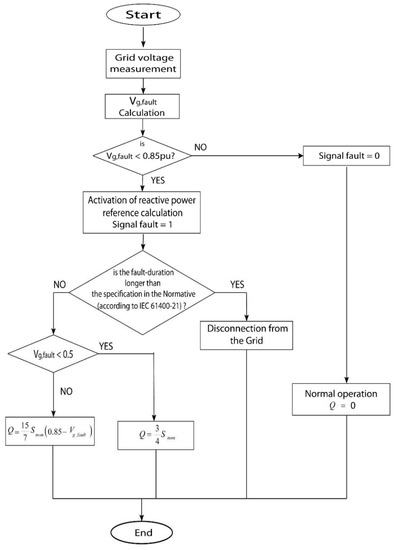
Figure 9.
Organigram of the LVRT algorithm.
4. Digital Real-Time Simulation of the RSC
In this section, the DRTS of the planned RSC control is presented. The dSPACE DS5202 signal acquisition board, together with the DS1006 processing board [52], is used for implementing the DRTS. These boards afford compatible libraries with MATLAB/Simulink software tool (R2010a, The MathWorks, Inc., Natick, MA, USA). Furthermore, dSPACE affords a monitoring software (ControlDesk) which communicates with the algorithm placed in the data acquisition board in real time.
The simulation model used in this study is made by using a 2 MW DFIG-based wind turbine as the most used generators for wind farms connected to the utility grid. Firstly, the RSC control of DFIG system with a fixed DC-link voltage (VDC = 800 V) is simulated with the MATLAB/Simulink environment, and secondly, the dSPACE blocks are added to the system in order to run in the digital real-time simulator. The generator parameters are given in Table 1.

Table 1.
DFIG system parameters.
Figure 10 shows the real-time simulation results of the RSC control at a step change in the wind turbine speed from 7 m/s to 12 m/s for a duration time of 10 s as represented in Figure 10a.
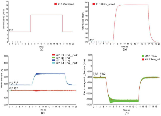
Figure 10.
DRTS of the RSC control for wind speed (a), rotor speed (b), rotor current (c), and electromagnetic torque (d).
According to Figure 10b, the RSC vector control guarantees the MPPT, the rotor mechanical speed changes with the wind speed variation and tracks his optimal value which ensure the MPPT capability. Moreover, the active current tracks the reference value with a quick dynamic performance, and without overshoots, as shown in Figure 10c, the active current value increase from to at the step beginning and return to the normal value with good control performance. The reactive current is well controlled and tracks the imposed reference value of 0 in order to minimize power losses (see Figure 10c). The same phenomena are observed for the electromagnetic torque which tracks this reference value with a good dynamic performance, as shown in Figure 10d.
5. Controller Hardware-in-the-Loop Simulation for the Grid-Side Converter
In this section, some tests are realized to verify the proposed GSC algorithm effectiveness by applying the HIL simulation [46,53]. This method uses a DRTS with various input/output digital signals, digital-to-analogue and analogue-to-digital converters, in order to simulate the power system behaviour in real time.
The platform for this study is built with the TMS320F28379D microcontroller from Texas Instruments [54] and the PLECS RT Box1 (Plexim) HIL boards with several analogues and digital input/outputs [55] (see Figure 11). The file with the C-code was created and uploaded into both targets [46], and the voltages and currents measurements are recorded in the host PC in order to monitor them as described in Figure 11. Table 2 and Table 3 present the power parameters for the grid side and the control subsystem parameters, respectively.
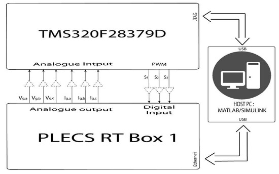
Figure 11.
CHIL block diagram.
Table 2.
The GSC power parameters.
Table 3.
Control subsystem parameters.
Four tests are assigned to deal with LVRT requirements at the three-phase output of the GSC in order to prove the strategy performance during different failure conditions. Generally, grid codes force the wind system to still connect even when grid voltage faults happen and inject reactive power to the utility grid according to the voltage depth level, forcing a grid currents limitation to its nominal amplitude. Consequently, there are two control modes for each test: the first mode is the control under normal conditions; the second control mode is based on the proposed LVRT strategy application, mainly activated when the grid voltage faults occur.
- Test 1: symmetrical voltage sag = 0.1 pu, duration t = 0.11 s, full nominal power (Figure 12) and half nominal power (Figure 13)
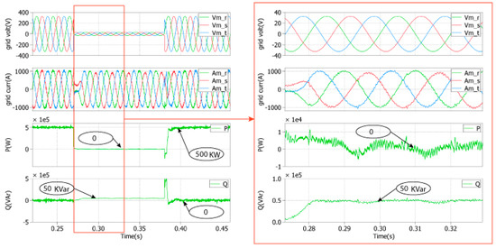 Figure 12. Simulation results of the proposed LVRT strategy for a symmetrical voltage sag of 0.1 pu under a full nominal power.
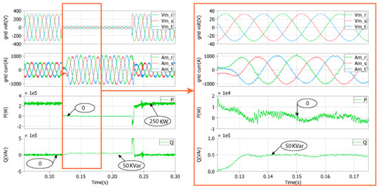 Figure 13. Simulation results of the LVRT proposed strategy for a symmetrical voltage sag of 0.1 pu under a half nominal power.
Figure 12 and Figure 13 present the GSC control strategy response to a three-phase voltage sag (0.1 pu) using the PR regulators under a full nominal power and a half nominal power, respectively, in order to verify the limitation imposed to the output grid currents. During the faults, it seems that the three-phase grid currents do not exceed the nominal value for both cases, injecting a reactive power of 50 kVAr and zero active power into the grid according to the grid code. Thus, the system control behaviour with PR regulators deals with the capability to inject the reactive power according to the grid code previously presented and with the limitation of three-phases grid current. Additionally, after the fault disappearance, the normal operation of the GSC controller is attained and the reactive power is zero for unity power factor operation.
- Test 2: symmetrical voltage sag = 0.3 pu, duration t = 0.11 s, full nominal power (Figure 14) and half nominal power (Figure 15)
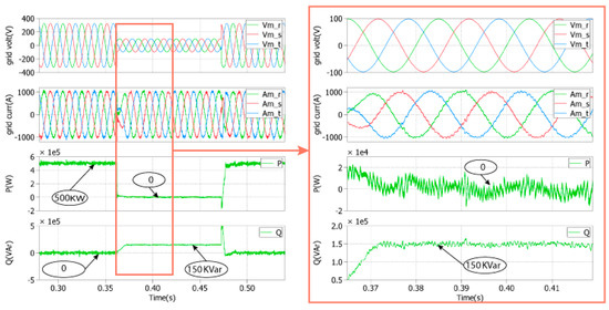 Figure 14. Simulation results of the proposed LVRT strategy for a symmetrical voltage sag of 0.3 pu under a full nominal power.
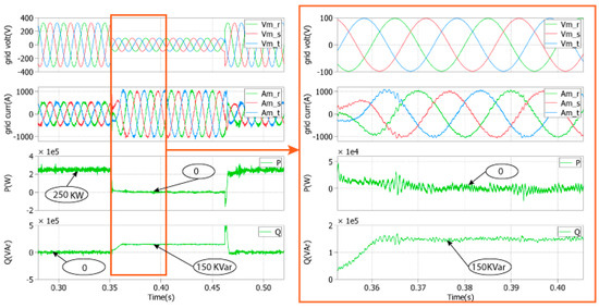 Figure 15. Simulation results of the proposed LVRT strategy for symmetrical voltage sag of 0.3 pu under a half nominal power.
In order to verify the capability of the proposed strategy during a deeper voltage dip, a voltage sag of 0.3 pu for the same duration (t = 0.11 s) is applied. Figure 14 and Figure 15 represent the GSC control strategy response to the symmetrical three-phase grid fault of 0.3 pu for the PR regulators under a full nominal power and a half nominal power, respectively, in order to verify the current limitation. During the faults, there is no overcurrent on the three-phase output grid currents, which means its nominal value is not exceeded for both cases. Meanwhile, the active power decrease to 0 and the reactive power increases to 150 kVAr. Thus, the used strategies behaviour deals with LVRT capability and injects reactive power according to the grid code. Additionally, when the grid fault ends, the normal operation of the GSC controller is achieved and the reactive power is zero.
- Test 3: asymmetrical voltage sag (one phase) = 0.1 pu, duration t = 0.25 s, full nominal power (Figure 16) and half nominal power (Figure 17)
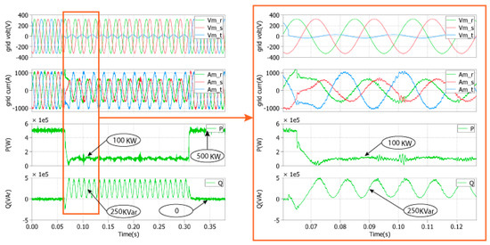 Figure 16. Simulation results of the proposed LVRT strategy for an asymmetrical voltage sag of 0.1 pu under a full nominal power.
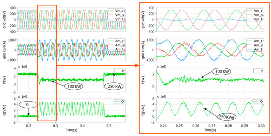 Figure 17. Simulation results of the proposed LVRT strategy for an asymmetrical voltage sag of 0.1 pu under a half nominal power.
In order to verify the PR controller capability under unbalanced grid faults, a deep voltage sag for a duration t of 0.27 s in phase 3 is applied under a full nominal power (Figure 16) and a half nominal power (Figure 17), respectively. As shown in Figure 16 and Figure 17, the three-phase grid currents do not exceed its nominal value for both cases; meanwhile, a specific quantity of active and reactive powers is injected into the utility grid. The oscillating nature of the reactive power during the unbalanced grid faults at twice the nominal frequency is due to the proper control of the negative sequence of the grid currents delivered to the grid, which also produces a constant active power control. However, the grid currents are unbalanced under this assumption. Finally, the system attains its normal operation when the unbalanced fault ends.
- Test 4: asymmetrical voltage sag (one phase) = 0.5 pu, duration t = 0.25 s, full nominal power (Figure 18) and half nominal power (Figure 19)
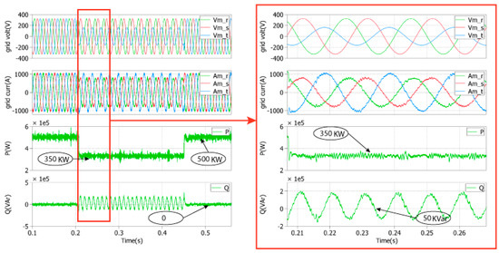 Figure 18. Simulation results of the proposed LVRT strategy for an asymmetrical voltage sag of 0.5 pu under a full nominal power.
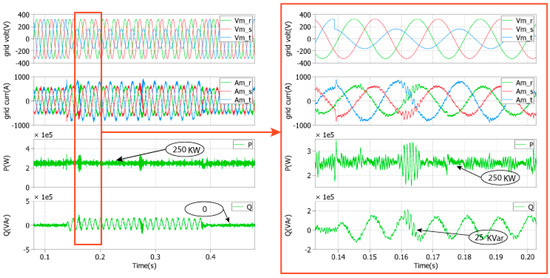 Figure 19. Simulation results of the proposed LVRT strategy for an asymmetrical voltage sag of 0.5 pu under a half nominal power.
In Figure 18 and Figure 19, the one-phase voltage test with the same duration of the previous test considers different levels of the grid voltage fault (0.5 pu), and the grid currents do not exceed its nominal amplitude value for both cases. Furthermore, because of the slight voltage drop compared to those in the previous tests, a higher active power is injected to the grid. Again, the reactive power oscillations during the unbalanced grid faults, for constant active power control, is due to the control of the negative sequence of the grid currents delivered to the grid; the system attains its normal operation when the unbalanced fault ends.
Finally, the GSC control strategy behaviour, dealing with the capability to inject the reactive power into the utility grid following the Spanish grid code previously presented and with the limitation of the three-phase grid currents amplitude, is validated.
6. Conclusions
The proposed control algorithms in this paper are used for a grid-connected DFIG to improve the quality of power and to deal with LVRT requirements according to the Spanish grid code. The vector control using the stator-flux-oriented control strategy has been applied to the RSC, and the performance of this control has been verified using the DRTS. Moreover, the GSC is controlled to compensate the reactive power and reduce the active power oscillations during the unbalanced grid operation. For this reason, the PR regulators have been proposed in the stationary reference frame in order to control the negative and positive sequences of the grid currents. The different types of grid voltage sags have been tested, and the experiments using CHIL simulation validate the proposed control algorithms for all tests, by limiting the amplitude of the grid currents, injecting the required reactive power and stabilizing the active power transferred into the grid.
Author Contributions
Y.E.K., A.B.R.-B. and H.E.M. developed the control approach and implemented the prototype; J.S. and T.I.S. provided the CHIL-based validation environment and supported Y.E.K., A.B.R.-B. and H.E.M. in the corresponding validation work; Y.E.K., A.B.R.-B. and H.E.M. wrote the main parts of the paper; J.S. and T.I.S. provided inputs for the validation part of the paper and all authors reviewed the paper.
Funding
This work was supported by: the project “Nuevas topologías para convertidores en MT para grandes Instalaciones Fotovoltaicas” from the Spanish Government (Ref. TEC2016-80136-P) (from A.B.R.); the European Community’s Horizon 2020 Program (H2020/2014-2020) in project “ERIGrid” (grant ggreement No. 654113) under the Trans-national Access (TA) User Project (Ref. 04.003-2018); and the Erasmus + KA107 mobility program 2018/2019 between Europe and Morocco, Universidad Politécnica de Cartagena (UPCT) & Sidi Mohamen Ben Abdellah University (USMBA)-Fez (from Y.E.K.).
Conflicts of Interest
The authors declare no conflict of interest.
References
- Shafiee, S.; Topal, E. When will fossil fuel reserves be diminished? Energy Policy 2009, 37, 181–189. [Google Scholar] [CrossRef]
- Lucas, H.; Pinnington, S.; Cabeza, L.F. Education and training gaps in the renewable energy sector. Sol. Energy 2018, 173, 449–455. [Google Scholar] [CrossRef]
- Bubshait, A.S.; Mortezaei, A.; Simoes, M.G.; Busarello, T.D.C. Power Quality Enhancement for a Grid Connected Wind Turbine Energy System. IEEE Trans. Ind. Appl. 2017, 53, 2495–2505. [Google Scholar] [CrossRef]
- Zhong, H.; Xia, Q.; Chen, Y.; Kang, C. Energy-saving generation dispatch toward a sustainable electric power industry in China. Energy Policy 2015, 83, 14–25. [Google Scholar] [CrossRef]
- Varaiya, P.P.; Wu, F.F.; Bialek, J.W. Smart Operation of Smart Grid: Risk-Limiting Dispatch. Proc. IEEE 2011, 99, 40–57. [Google Scholar] [CrossRef]
- Alsmadi, Y.M.; Xu, L.; Blaabjerg, F.; Ortega, A.J.P.; Abdelaziz, A.Y.; Wang, A.; Albataineh, Z. Detailed Investigation and Performance Improvement of the Dynamic Behavior of Grid-Connected DFIG-Based Wind Turbines Under LVRT Conditions. IEEE Trans. Ind. Appl. 2018, 54, 4795–4812. [Google Scholar] [CrossRef]
- Chabani, M.S.; Benchouia, M.T.; Golea, A.; Boumaaraf, R. Implementation of direct stator voltage control of stand-alone DFIG-based wind energy conversion system. In Proceedings of the 2017 5th International Conference on Electrical Engineering—Boumerdes (ICEE-B), Boumerdes, Algeria, 29–31 October 2017; pp. 1–6. [Google Scholar]
- Awedni, O.; Masmoudi, A.; Krichen, L. Power Control of DFIG-Based Wind Farm for System Frequency Support. In Proceedings of the 2018 15th International Multi-Conference on Systems, Signals & Devices (SSD), Hammamet, Tunisia, 19–22 March 2018; pp. 1298–1304. [Google Scholar]
- El Karkri, Y.; El Markhi, H.; El Moussaou, H.; Lamhamdi, T. LVRT and HVRT control strategies of Doubly-Fed Induction Generator. J. Electr. Syst. 2018, 14, 1–20. [Google Scholar]
- Li, G.H.; Zhang, B.H.; Hao, Z.G.; Wang, J.; Bo, Z.Q.; Writer, D.; Yip, T. Modeling of DFIG based wind generator and transient characteristics analysis. In Proceedings of the 2011 10th International Conference on Environment and Electrical Engineering, Rome, Italy, 8–11 May 2011; pp. 1–4. [Google Scholar]
- Lei, T.; Ozakturk, M.; Barnes, M. Modelling and analysis of DFIG wind turbine system in PSCAD/EMTDC. In Proceedings of the 6th IET International Conference on Power Electronics, Machines and Drives (PEMD 2012), Bristol, UK, 27–29 March 2012; p. 13. [Google Scholar]
- Piya, P.; Ebrahimi, M.; Karimi-Ghartemani, M.; Khajehoddin, S.A. Fault Ride-Through Capability of Voltage-Controlled Inverters. IEEE Trans. Ind. Electron. 2018, 65, 7933–7943. [Google Scholar] [CrossRef]
- Massmann, J.; Erlinghagen, P.; Schnettler, A. Impact of Distributed Generation’s Fault Ride Through Strategies on System Stability in the Transmission Grid. In Proceedings of the 2018 Power Systems Computation Conference (PSCC), Dublin, Ireland, 11–15 June 2018; pp. 1–8. [Google Scholar]
- Rauf, A.M.; Khadkikar, V.; El Moursi, M.S. A New Fault Ride-Through (FRT) Topology for Induction Generator Based Wind Energy Conversion Systems. IEEE Trans. Power Deliv. 2019, 34, 1129–1137. [Google Scholar] [CrossRef]
- Li, W.; Chao, P.; Liang, X.; Sun, Y.; Qi, J.; Chang, X. Modeling of complete fault ride-through processes for DFIG-Based wind turbines. Renew. Energy 2018, 118, 1001–1014. [Google Scholar] [CrossRef]
- Institution of Engineering and Technology; Papathanassiou, S. IET Renewable Power Generation; Institution of Engineering and Technology: Stevenage, UK, 2007; Volume 3. [Google Scholar]
- El Makrini, A.; El Karkri, Y.; Boukhriss, Y.; El Markhi, H.; El Moussaoui, H. Control Strategy of DFIG Based Wind Turbines Combined the Active and Passive Protections. Int. J. Renew. Energy Res. 2017, 7, 1258–1269. [Google Scholar]
- Cao, P.; Shu, H.; Yang, B.; An, N.; Qiu, D.; Teng, W.; Dong, J.; Cao, P.; Shu, H.; Yang, B.; et al. Voltage Distribution–Based Fault Location for Half-Wavelength Transmission Line with Large-Scale Wind Power Integration in China. Energies 2018, 11, 593. [Google Scholar] [CrossRef]
- Ayodele, T.; Jimoh, A.; Munda, J.; Agee, J. Challenges of Grid Integration of Wind Power on Power System Grid Integrity: A Review. Int. J. Renew. Energy Res. 2012, 2, 618–626. [Google Scholar]
- Firouzi, M.; Gharehpetian, G.B. LVRT Performance Enhancement of DFIG-Based Wind Farms by Capacitive Bridge-Type Fault Current Limiter. IEEE Trans. Sustain. Energy 2018, 9, 1118–1125. [Google Scholar] [CrossRef]
- Gholizadeh, M.; Tohidi, S.; Oraee, A.; Oraee, H. Appropriate crowbar protection for improvement of brushless DFIG LVRT during asymmetrical voltage dips. Int. J. Electr. Power Energy Syst. 2018, 95, 1–10. [Google Scholar] [CrossRef]
- El Karkri, Y.; El Markhi, H.; Lamhamdi, T.; El Moussaoui, H. A comparison between Series Dynamic Resistors and CROWBAR circuit protection for LVRT capability of Doubly-Fed Induction Generator. IOP Conf. Ser. Earth Environ. Sci. 2018, 161, 12012. [Google Scholar] [CrossRef]
- Li, S.; Haskew, T.A.; Williams, K.A.; Swatloski, R.P. Control of DFIG Wind Turbine With Direct-Current Vector Control Configuration. IEEE Trans. Sustain. Energy 2012, 3, 1–11. [Google Scholar] [CrossRef]
- Sidi, Y.E.; Ben, M.; El, H.; Sidi, M.; Karkri, E.L.; El Karkri, Y.; El Markhi, H.; El Moussaou, H.; Lamhamdi, T. LVRT and HVRT control strategies of DoublyFed Induction Generator Grid integration of renewable energy sources View project Wind turbine integration View project. J. Electr. Syst. 2018, 14, 1–20. [Google Scholar]
- Li, S.; Haskew, T.A. Analysis of Decoupled d-q Vector Control in DFIG Back-to-Back PWM Converter. In Proceedings of the 2007 IEEE Power Engineering Society General Meeting, Tampa, FL, USA, 24–28 June 2007; pp. 1–7. [Google Scholar]
- Li, S.-Y.; Sun, Y.; Wu, T.; Liang, Y.-Z.; Yu, X.; Zhang, J.-M. Analysis of Low Voltage Ride through Capability in Wind Turbine Based on DFIG. In Proceedings of the 2010 International Conference on Electrical and Control Engineering, Wuhan, China, 25–27 June 2010; pp. 3331–3334. [Google Scholar]
- Chowdhury, M.A.; Hosseinzadeh, N.; Billah, M.M.; Haque, S.A. Dynamic DFIG wind farm model with an aggregation technique. In Proceedings of the International Conference on Electrical & Computer Engineering (ICECE 2010), Dhaka, Bangladesh, 18–20 December 2010; pp. 330–333. [Google Scholar]
- Bian, X.; Tse, C.T.; Chung, C.Y.; Wang, K.W. Dynamic modeling of large scale power system with FACTS and DFIG type wind turbine. In Proceedings of the The 2nd International Symposium on Power Electronics for Distributed Generation Systems, Hefei, China, 16–18 June 2010; pp. 753–758. [Google Scholar]
- Joo, I.W.; Song, H.S.; Nam, K. Source-voltage-sensorless scheme for PWM rectifier under voltage unbalance condition. In Proceedings of the 4th IEEE International Conference on Power Electronics and Drive Systems. IEEE PEDS 2001—Indonesia. Proceedings (Cat. No.01TH8594), Denpasar, Indonesia, 25 October 2001; Volume 1, pp. 33–38. [Google Scholar]
- Song, H.S.; Nam, K. Dual current control scheme for PWM converter under unbalanced input voltage conditions. IEEE Trans. Ind. Electron. 1999, 46, 953–959. [Google Scholar] [CrossRef]
- Xu, L. Coordinated Control of DFIG’s Rotor and Grid Side Converters During Network Unbalance. IEEE Trans. Power Electron. 2008, 23, 1041–1049. [Google Scholar]
- Xu, L.; Andersen, B.R.; Cartwright, P. VSC Transmission Operating Under Unbalanced AC Conditions—Analysis and Control Design. IEEE Trans. Power Deliv. 2005, 20, 427–434. [Google Scholar] [CrossRef]
- Etxeberria-Otadui, I.; Lopez De Heredia, A.; Gaztanaga, H.; Bacha, S.; Reyero, M.R. A Single Synchronous Frame Hybrid (SSFH) Multifrequency Controller for Power Active Filters. IEEE Trans. Ind. Electron. 2006, 53, 1640–1648. [Google Scholar] [CrossRef]
- Etxeberria-Otadui, I.; Viscarret, U.; Caballero, M.; Rufer, A.; Bacha, S. New Optimized PWM VSC Control Structures and Strategies Under Unbalanced Voltage Transients. IEEE Trans. Ind. Electron. 2007, 54, 2902–2914. [Google Scholar] [CrossRef]
- Liserre, M.; Teodorescu, R.; Blaabjerg, F. Multiple harmonics control for three-phase grid converter systems with the use of PI-RES current controller in a rotating frame. IEEE Trans. Power Electron. 2006, 21, 836–841. [Google Scholar] [CrossRef]
- Hu, J.; He, Y.; Nian, H. Enhanced control of DFIG-used back-to-back PWM VSC under unbalanced grid voltage conditions. J. Zhejiang Univ. Sci. A 2007, 8, 1330–1339. [Google Scholar] [CrossRef]
- Chomat, M. Extended vector control of doubly fed machine under unbalanced power network conditions. In Proceedings of the International Conference on Power Electronics Machines and Drives, Sante Fe, NM, USA, 4–7 June 2002; Volume 2002, pp. 329–334. [Google Scholar]
- Iwanski, G.; Koczara, W. Sensorless direct voltage control method for stand-alone slip-ring induction generator. In Proceedings of the 2005 European Conference on Power Electronics and Applications, Dresden, Germany, 11–14 September 2005; p. 10. [Google Scholar]
- Martinez-Rodrigo, F.; Ramirez, D.; Rey-Boue, A.B.; De Pablo, S.; Herrero-De Lucas, L.C. Modular multilevel converters: Control and applications. Energies 2017, 10, 1709. [Google Scholar] [CrossRef]
- Limongi, L.R.; Bojoi, R.; Griva, G.; Tenconi, A. Digital current-control schemes. IEEE Ind. Electron. Mag. 2009, 3, 20–31. [Google Scholar] [CrossRef]
- Jaalam, N.; Rahim, N.A.; Bakar, A.H.A.; Eid, B.M. Strategy to enhance the low-voltage ride-through in photovoltaic system during multi-mode transition. Sol. Energy 2017, 153, 744–754. [Google Scholar] [CrossRef]
- Sefa, I.; Altin, N.; Ozdemir, S.; Demirtas, M. dSPACE based control of voltage source utility interactive inverter. In Proceedings of the 2008 International Symposium on Power Electronics, Electrical Drives, Automation and Motion, Ischia, Italy, 11–13 June 2008; pp. 662–666. [Google Scholar]
- Liao, Y.; Li, H.; Yao, J.; Zhuang, K. Operation and control of a grid-connected DFIG-based wind turbine with series grid-side converter during network unbalance. Electr. Power Syst. Res. 2011, 81, 228–236. [Google Scholar] [CrossRef]
- Hamon, C. Doubly-fed Induction Generator Modeling and Control in DigSilent Power Factory. In Proceedings of the 2010 International Conference on Power System Technology, Hangzhou, China, 24–28 October 2010. [Google Scholar]
- Baros, S.; Ilic, M. Robust ectropy-based cooperative control of a wind DFIG for transient stabilization and MPPT. In Proceedings of the 2015 IEEE Power & Energy Society General Meeting, Denver, CO, USA, 26–30 July 2015; pp. 1–5. [Google Scholar]
- Rey-Boué, A.B.; Martinez-Rodrigo, F.; Guerrero-Rodríguez, N.F.; Herrero-de Lucas, L.C.; de Pablo, S. Enhanced controller for grid-connected modular multilevel converters in distorted utility grids. Electr. Power Syst. Res. 2018, 163, 310–327. [Google Scholar] [CrossRef]
- Gulur, S.; Iyer, V.M.; Bhattacharya, S. Proportional integral—Resonant and dual loop current control structure comparison for grid connected converters in the rotating frame. In Proceedings of the 2018 IEEE Applied Power Electronics Conference and Exposition (APEC), San Antonio, TX, USA, 4–8 March 2018; pp. 1617–1623. [Google Scholar]
- Zhang, N.; Tang, H.; Yao, C.; Zhang, N.; Tang, H.; Yao, C. A Systematic Method for Designing a PR Controller and Active Damping of the LCL Filter for Single-Phase Grid-Connected PV Inverters. Energies 2014, 7, 3934–3954. [Google Scholar] [CrossRef]
- Afshari, E.; Moradi, G.R.; Rahimi, R.; Farhangi, B.; Yang, Y.; Blaabjerg, F.; Farhangi, S. Control Strategy for Three-Phase Grid-Connected PV Inverters Enabling Current Limitation Under Unbalanced Faults. IEEE Trans. Ind. Electron. 2017, 64, 8908–8918. [Google Scholar] [CrossRef]
- Guerrero-Rodríguez, N.F.; Herrero-de Lucas, L.C.; de Pablo-Gómez, S.; Rey-Boué, A.B. Performance study of a synchronization algorithm for a 3-phase photovoltaic grid-connected system under harmonic distortions and unbalances. Electr. Power Syst. Res. 2014, 116, 252–265. [Google Scholar] [CrossRef]
- Gómez, E.; Fuentes, J.A.; Molina-García, A.; Ruz, F.; Jiménez, F. Field tests of wind turbines submitted to real voltage dips under the new Spanish grid code requirements. Wind Energy 2007, 10, 483–495. [Google Scholar] [CrossRef]
- Santos-Martin, D.; Alonso-Martinez, J.; Eloy-Garcia Carrasco, J.; Arnaltes, S. Problem-Based Learning in Wind Energy Using Virtual and Real Setups. IEEE Trans. Educ. 2012, 55, 126–134. [Google Scholar] [CrossRef]
- Liu, C.; Chen, B.; Cheng, M.; Champagne, A.; Patel, K. Model Integration and Hardware-in-the-Loop (HiL) Simulation Design for the Testing of Electric Power Steering Controllers. SAE Tech. Pap. 2016. [Google Scholar] [CrossRef]
- Chun, T.W.; Choi, M.G.; Kim, K.M. A programmable low-pass filter based stator flux calculation for a direct vector control of induction motor. In Proceedings of the Proceedings Third Russian-Korean International Symposium on Science and Technology. KORUS’99 (Cat. No.99EX362), Novosibirsk, Russia, 22–25 June 1999; Volume 2, pp. 722–726. [Google Scholar]
- Lemaire, M.; Sicard, P.; Belanger, J. Prototyping and Testing Power Electronics Systems Using Controller Hardware-In-the-Loop (HIL) and Power Hardware-In-the-Loop (PHIL) Simulations. In Proceedings of the 2015 IEEE Vehicle Power and Propulsion Conference (VPPC), Montreal, QC, Canada, 19–22 October 2015; pp. 1–6. [Google Scholar]


© 2019 by the authors. Licensee MDPI, Basel, Switzerland. This article is an open access article distributed under the terms and conditions of the Creative Commons Attribution (CC BY) license (http://creativecommons.org/licenses/by/4.0/).