1. Introduction
Marine Renewable Energy (MRE) is one of the least tapped renewable energy resources. Despite decades of development efforts, more than 90% of the 529 MW of the MRE operating capacity at the end of 2017 was represented mainly by two tidal barrage facilities: 254 MW from Sihwa plant in the Republic of Korea (completed in 2011) and the 240 MW La Rance tidal power station in France (built in 1966) [
1]. Main barriers for MRE causing this slow development are analyzed in [
2] with special interest in the Mediterranean Sea (MS), although the results can be applied to a great extent for any other geographical areas. Remarkable conclusions about MRE barriers include:
Bathymetry and distance to shore: Near-shore facilities can have a direct affection on nearby coastal areas, maritime routes, fishing areas or visual impacts. Narrow and step near-shore continental shelfs can also have a negative impact for economic reasons, mainly installation (including grid connectivity) and maintenance.
Electricity infrastructure: On the contrary, if we move large distances from the shore to minimize the previously cited negative impacts over coastal areas, it can significantly increase the relevant cost of cabling and substations, especially for areas with large depths.
Potential environmental impacts: Underwater noise, sediment dispersal, increased turbidity, electromagnetic field effects (EMF), wave radiation and diffraction alteration can lead to significant changes to coastal morphology; fixed structures can also generate artificial reef effect. It is concluded that environmental impacts for MRE are hardly clear and not sufficiently quantified, hence, more research is necessary about this topic.
Economics: The great diversity of MRE technologies and the early development status result in a wide range of levelized cost of energy (LCOE) [
3], in the particular case of wave energy ranging from 108 €/MWh to 530 €/MWh. This level of economic uncertainty creates a less favorable environment for investments.
Legal and regulatory framework: There is a lot of uncertainty in this regard for MRE, and it is not adequately addressed by the relevant national/international entities. Many key parameters affecting directly any MRE installation are interrelated with several other aspects such as the environmental impact assessment, rights and ownership, international law, management of ocean space, etc.
Geographical or energy islands remain as the most interesting technological enablers for MRE research and deployment, as highlighted in [
4]. For remote areas or small islands, the electrical energy production is still based on outdated, polluting and expensive technologies, powered by fossil fuels. Many islands around the world are working on important projects in order to achieve energetic independence based on MRE. Hybrid solutions such as solar-wave [
5] or wind-wave [
6] can also favor the development of MRE, combining more stablished technologies such as offshore wind and PV in the same offshore device (e.g., spar sharing) or energy farm.
MRE technologies have seen new capacity come online over the recent years; in particular, wave energy development in Spain [
7] holds some notorious projects, such as the so called MARMOK-A-5 being the first operational point absorber connected to the grid in Spain, developed by OCEANTEC (acquired by IDOM in September 2018), installed at BIMEP test site in 2016. Mutriku Wave Power Plant, operates since July 2011 connected to the grid, being the first oscillating water column (OWC) multi-turbine facility acting as a test rig for different technology developers; the Portuguese company Kymaner finished testing of its bi-radial air turbine last August 2018. WEP+ demonstration project, based on the industrial scale W1 point absorber developed by Wedge Global, accumulated roughly 5 years of testing at PLOCAN test site on the Canary Islands. LifeDemoWave demonstration project deployed a 25-kW prototype in June 2018 in the Galician coast for a no grid connected test. European highlights from 2018 resulted from H2020 funded projects, including the fabrication of the second Penguin Wave Energy Converter (WEC) at EMEC as part of the CEFOW project, the deployment of the Corpower WEC at EMEC, the installation of the new turbine on the Marmok wave device and the deployment of Minesto’s Deepgreen500 device.
The wave energy sector is still in a very early development stage when compared to other renewable energies, especially wind or solar PV. There is a low level of consensus among the WEC technology developers that are still, at best, in a prototype demonstration phase, and there is a lot of discussion among said developers about the best WEC topology and/or PTO configurations. It is not so common to discuss at this level about control strategies given the difficulties in effectively implementing most of the control strategies listed in
Section 3 of this review. Most of the existing industry scale prototypes in the water have the simplest control strategy resulting in low energy absorption.
The main purpose of this article is to establish a framework for the control strategies being discussed over the recent years (2017–2019) for WECs. References older than 2017 will not be discussed (unless for introductory purposes) to avoid redundancies with older reviews with a similar approach. A brief review will be provided about the analytical formulation of the mean power absorption and optimal control [
8] particularized for heaving WECs, which is the most extended WEC technology in the form of floating point absorbers [
9]; however, the same approach is extensible to any other oscillatory mode (sway, surge, pitch, roll or yaw). A point absorber is a floating buoy moored (2 bodies) or fixed (1 body) to the seabed. The incoming waves induce into the floating body a synchronous oscillation mainly in heave motion. It is this movement that is converted into an energy vector (e.g., hydrogen [
10], desalination [
11] or electricity) through a power take-off located inside the buoy.
Great effort has been made in the last decades about control strategies for WEC, as we can see from older state-of-the-art reviews such as [
12,
13,
14]. The main objective in wave energy conversion for control is the maximization of power absorption, aiming for resonance operation. The best control approach to achieve said resonance is known as complex-conjugate control, based on solving the impedance matching problem. As we will explain later, this control always achieves optimal power absorption since it regulates the system reactance and resistance simultaneously. However, this control strategy is not practical for real world applications because of large motions and loads. Hence, under-optimal control solutions, it needs to be analyzed and implemented considering physical constrains in motion, force and power rating of the WEC.
In
Section 2 a brief introduction about wave energy technology is presented with the purpose of helping the uninitiated reader understand the different technologies and parts (oscillator body, PTO) of WECs. In
Section 3, we will start with a comprehensive introduction for WEC modelling and optimal control, as originally introduced in [
15], to establish a reference framework, continuing with classification, introduction and discussion for each control strategy found in recent WEC control publications. Finally, conclusion and further research end the article in
Section 4.
2. Wave Energy Technology
In the same way that a wind turbine transforms the kinetic energy of the wind into mechanical energy of rotation through the blades, and this one into electrical energy through the electrical generator, a WEC transforms the energy from the waves into mechanical energy through the oscillating body and this one into an energy vector through the PTO.
In the wind energy sector, there is a predominant type over the rest, the three-bladed horizontal axis turbine; it is not so for wave energy, where there is a wide spectrum of options for both oscillator body and PTO without a clear predominant type. Over 1000 different wave energy conversion techniques were patented in Japan, North America and Europe [
16] just in 2004, and it is expected this number has greatly increased since 2004 based on the general renewables energies patent numbers shared recently by EMW Law [
17].
2.1. Wave Energy Converters
Despite the great number of different technologies for harvesting wave energy, all of them can generally be categorized on the basis of three criteria [
18,
19,
20,
21].
2.1.1. Location
This classification is according to the relative distance between the device, coast and seabed depth. This classification is somehow qualitative because of the many differences between continental shelfs around the world. Nevertheless, this classification is not used in practical discussions and remains as a first qualitative approach to WEC technologies.
Onshore: Located in coast proximity, commonly affected by swallow waters (h/λ < 1/25), where h is the water depth and λ is the wavelength. These converters are usually integrated in a breakwater, dam, fixed to a cliff or rest on the seabed. The distinctive characteristics for these converters are easy maintenance and installation. The drawbacks are that coastline waves have less energy than deep-water waves along with a potential coastline reshape.
Nearshore: They are installed close to the shore, commonly affected by swallow or intermediate waters (1/25 < h/λ < 1/2). Their deployment and maintenance expenses are limited since they do not need mooring systems as they are usually fixed or rest on the seabed.
Offshore: They are placed in deep waters (h/λ > 1/2), far from the shore. They are able to harvest energy from the most energetic places, but installation and maintenance can be much more expensive because of the required mooring systems (high depth), long underwater cabling, underwater substations and offshore maintenance.
2.1.2. Dimensions of the Prime Mover and Orientation with Respect to the Wave
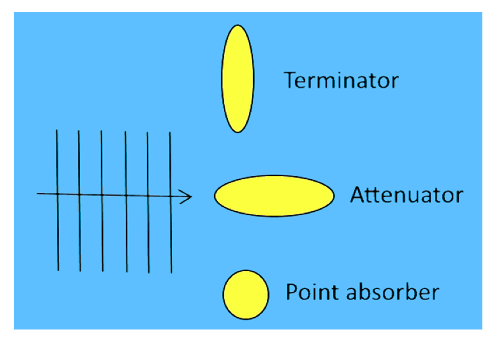
This classification is according to the orientation of the wave energy device with respect to the wave propagation front (
Figure 1). This classification along with the working principle are used to clearly differentiate any WEC.
Attenuators: The length of the device is of the same order of magnitude (or larger) than the wavelength; these devices are oriented in such a way that they are parallel to the incident wave.
Terminators: Similar in dimensions to attenuators but placed perpendicular to the incident wave.
Point Absorbers: Axisymmetric devices capable of harvesting waves from any direction, known as antenna effect, their dimensions are usually an order of magnitude lower than the wavelength.
2.1.3. Working Principle
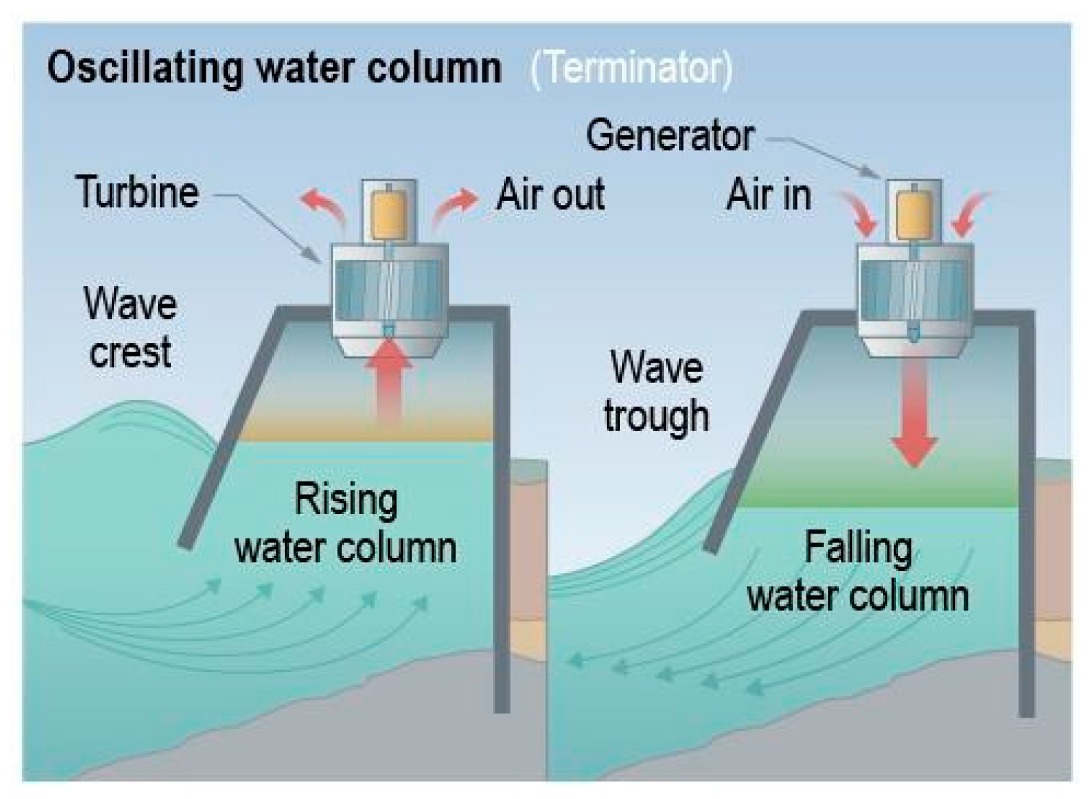
Oscillating water column: This type of technology builds, among its main elements, an air chamber. It is this air, subjected to oscillating pressure by the action of the waves, which ascends or descends moving a conventional air turbine linked to an electrical generator (
Figure 2). Hence, the air turbine can take advantage of the complete oscillation cycle of the wave. It is generally installed in a breakwater, but there are shore-based and floating models. The main benefits for oscillating water column concept commonly accepted are its simplicity and robustness [
22]. Common examples are Oceanlinx device deployed in 2005 designed to sit in shallow water, approximately 21 m wide and 24 m long, and Mutriku wave energy plant, located in the Bay of Biscay and commissioned in July 2011, which is one of the few wave energy plants still in operation.
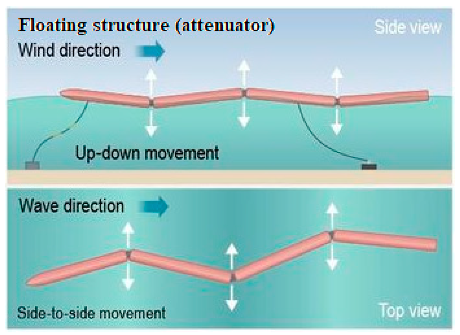
Floating structures: Unibody or multibody structures moving in heave, pitch, roll or in any combination of the three (
Figure 3) when affected by a wave. The relative movement between different parts of the device allows converting it into electricity. These kinds of devices are rarely named as floating structures but using the dimensions with respect to the wave: attenuators or floating-point absorbers. Multiple examples can be found for this kind of technology. Pelamis was an attenuator floating structure deployed during 2007. The machine is composed by a number of semi-submerged, linked sections. These sections move relatively when the waves pass along the length of the machine. W1 is a point absorber floating technology deployed in 2014. The machine has two main bodies linked without restrictions in heave motion, which allows the relative movement between them.
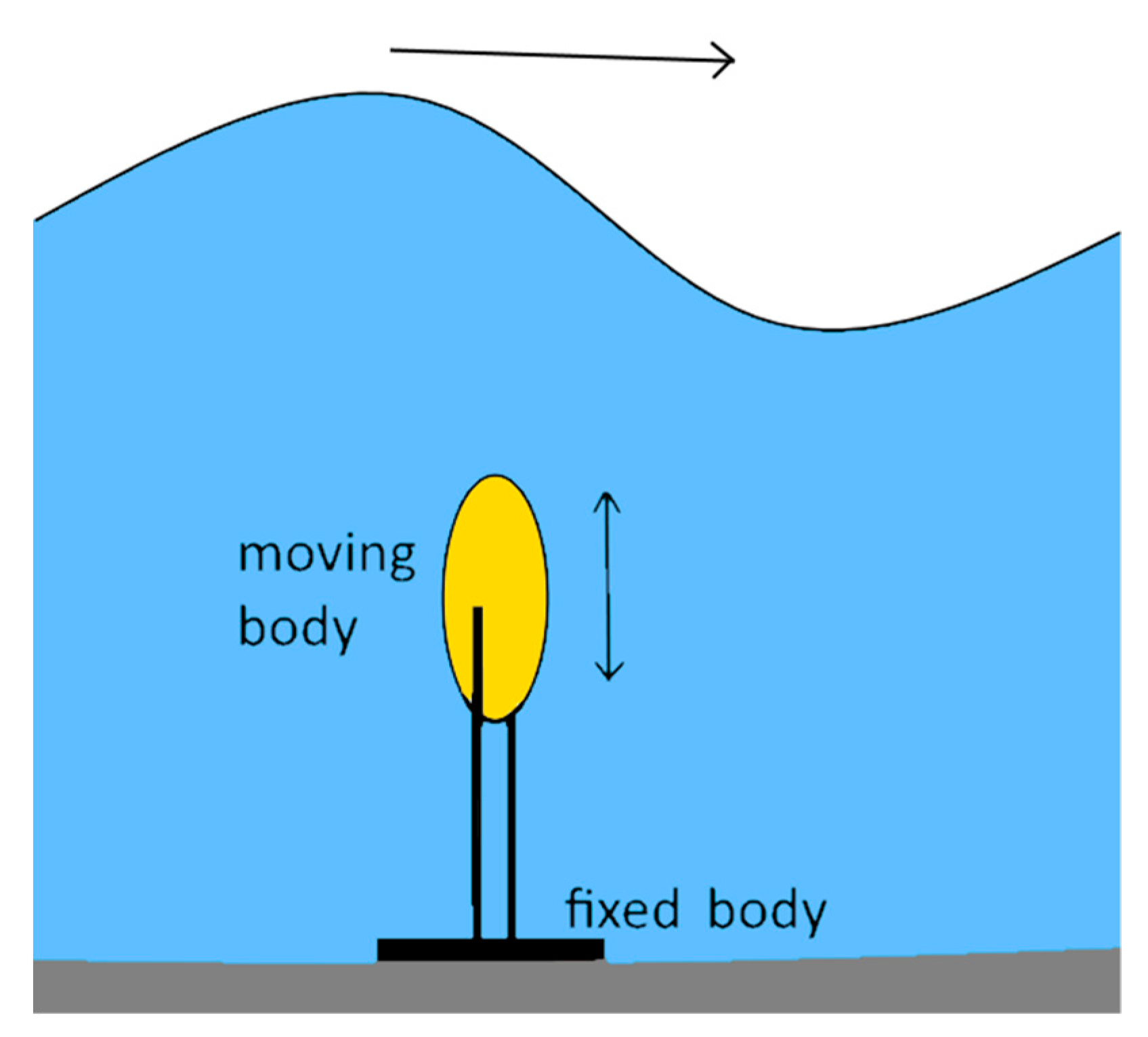
Pressure differential: Typically located nearshore, this kind of technology can be explained as a combination of two technologies working together—oscillating water column and floating point-absorbers. This is because it uses the working principle for both: difference of pressure and relative heave/pitch/roll displacement between parts, the fixed air chamber in the seabed and the moveable upper body (
Figure 4). When a wave crest passes over the device, the water pressure above the device compresses the air within the cylinder, moving the upper cylinder down creating a relative movement in the same way as in punctual absorbers, this happens in the opposite way when a trough passes over. Potential advantages of these devices include: Better survivability, they are not exposed to splash zone corrosion nor the various hazards that could take effect when floating on surface and reduced/negligible visual impact. A major drawback for pressure differential technology is the required underwater maintenance. A good example of evolution with pressure differential technology is Carnegie Clean Energy device (CETO). Deployed in 2015, CETO 5 served the purpose of delivering pressured water for reverse osmosis membranes in the desalination plant, but CETO 6 (still in development) will include electrical generation onboard.
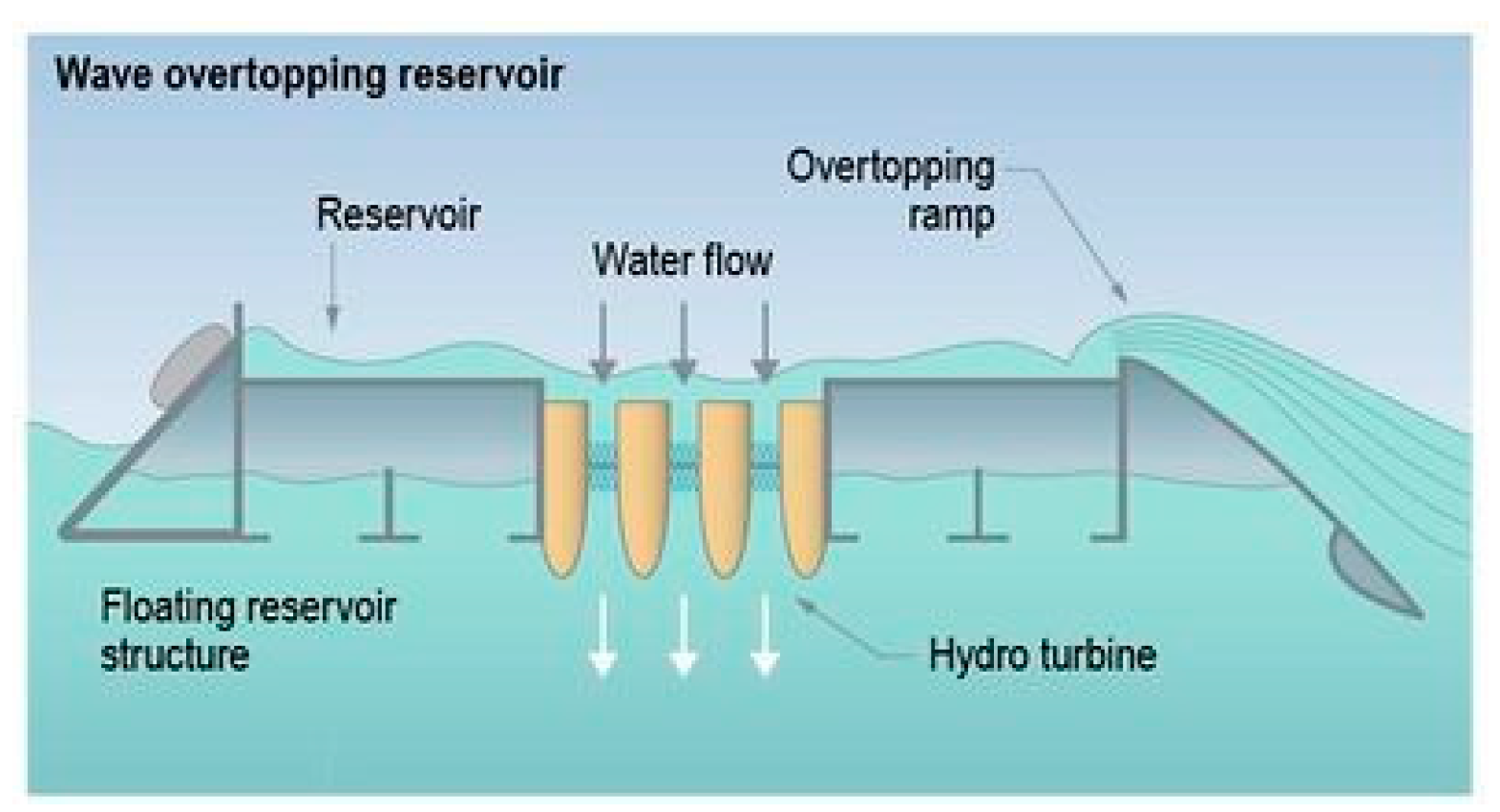
Overtopping devices: These devices collect the water from the incident waves into a reservoir in order to move one or more reduced jump hydraulic turbines, usually Kaplan turbines. They take advantage of the potential energy of the waves to convert it, through synchronous generators, into electrical energy (
Figure 5). Within this type of device, we can distinguish between converters with a fixed structure located on the coast (onshore) and those with a floating structure far away from it (nearshore–offshore). A common example of these kind of devices is the Wave Dragon [
23], which is characterized by having a reflector that directs the incident waves towards a ramp to the reservoir above sea level.
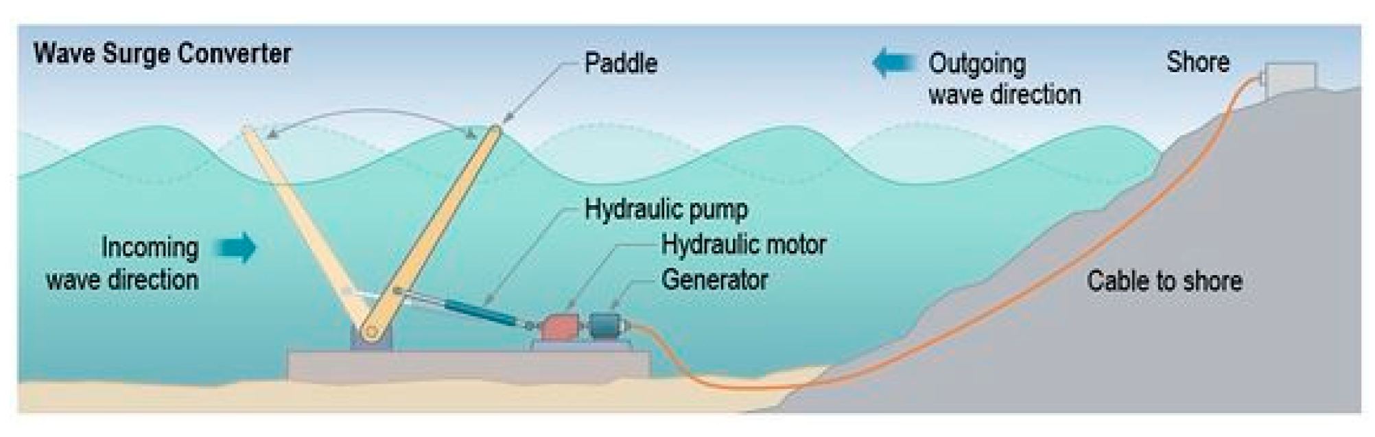
Oscillating wave surge: These devices typically have one end attached to a fixed structure or the bottom of the sea while the other end is free to move. A hinged deflector, this part is positioned perpendicular to the wave direction, terminator (
Figure 6). The axis of the deflector (or paddle) oscillates like a pendulum mounted on a pivoting joint in response to the impact of the horizontal movement of the wave particle. They often come in the form of floats, fins or membranes. This working principle could be associated to the unique Japanese ‘Pendulor’ system [
24]; but these devices do not take advantage of any harbor resonance. An example for this kind of technology is the Aquamarine Power Oyster, a nearshore device, where the top of the deflector is above the water surface and is hinged from the sea bed.
2.2. Power Take-Off Systems
In this section, a brief introduction for each of the different PTO technologies, as presented in [
18,
25,
26,
27], is given. Three main technology paths can be applied to obtain electricity from the wave power conversion chain (PCC), converting the energy being carried by the wave into fluid capture, linear motion or rotary motion. Many different rotary electrical solutions can be applied, but these technologies imply a lot of intermediate steps: Pistons, accumulators, air chambers or mechanical gear systems [
25]. The number of intermediate steps is critical for the wave energy conversion efficiency and reliability:
Efficiency: The larger the number of intermediate steps, the greater are the mechanical and transformation losses that we obtain as a result of the PCC. This causes a reduction in the annual energy production (AEP), which in turn affects the levelized cost of the electricity (LCOE), increasing it.
Reliability: The offshore equipment undergoes an accelerated degradation in comparison with the same equipment implemented within a ground installation due to the high salinity of the maritime environment where it is implemented. This fact makes it desirable to minimize the amount of equipment to monitor and maintain while the equipment is in operation.
2.2.1. Air Turbines
Commonly used in OWC devices, air turbines require an air chamber to convert wave energy into mechanical power (
Section 2.1.3). The basic principle is to drive the air turbine with the oscillating air pressure in the air chamber as a consequence of the oscillating water level. As a result, this PTO solution presents a challenge coming from the bidirectional nature of the flow. A possible solution for this challenge includes non-returning valves combined with a conventional turbine. However, due to complexity, size and high maintenance costs, this configuration is not considered as a viable option [
25]. A better solution involves a self-rectifying air turbine that converts an alternating air flow into a unidirectional rotation.
2.2.2. Hydraulic Systems
These are typically used in attenuators, point absorbers and wave surge devices (
Section 2.1.3), in which the energy conversion system is based on taking advantage of the linear movement generated by the interaction of the body (or bodies) with the waves. Conventional rotary electrical solutions may not be directly compatible [
25]. Therefore, a suitable conversion interface is required between the linear energy capture and the electrical generator, capable of operating with high forces at low frequencies, such as hydraulic systems that operate reversed with respect to their traditional counterpart, that is, the movement of the body feeds the energy of the hydraulic motor which in turn feeds an electric generator.
2.2.3. Hydro Turbines
Used for overtopping devices [
25], hydraulic turbines [
28] take advantage of the potential energy of the water stored in the accumulation chamber of the device, which is converted to mechanical power using low-head turbines and rotary electrical generators.
2.2.4. Direct Mechanical Drive Systems
This form of PTO solution requires additional mechanical systems driving a rotary electrical generator [
25]. It can comprise pulleys, cables, gear boxes or energy storage systems, such as Flywheels (for rotation-based systems) in order to accumulate and release energy, if needed, for reactive operation or to smooth any power variation.
2.2.5. Direct Electrical Drive Systems
Direct electrical drive PTO directly couples the moving part of the electrical generator with the moving body of the WEC [
25]. A direct electrical drive PTO system presents two main parts: (i) a translator coupled to the moving body of the WEC, which can be equipped with permanent magnets (conventional solution) or magnetic steel (switched reluctance) and (ii) the stator equipped with coils. The waves induce a heave motion in the moving body coupled with the translator, generating a relative displacement of the translator within the stator, inducing electrical current.
Critical added value of direct linear drive systems is the ability to move instantly in any of the 4-quadrant modes of operation, commonly called 4-quadrant control, allowing instant swap from motor to generator mode at any given moment of the wave oscillation cycle (upwards or downwards) to handle the required reactive power for some of the control strategies we will list in
Section 3.
In the first (I) and third (III) quadrants, the electric machine delivers positive power, clockwise or counterclockwise, supplying mechanical energy (motor). On the other hand, in the second (II) and fourth (IV) quadrants, the electric machine delivers negative power, supplying electrical power (generator). Applying a single cycle of regular waves to a WEC, for example, the period between two consecutive wave peaks, the required operation for each quadrant will be as follows: During the downward movement the electric machine will work in downward generator mode (quadrant II) once it reaches the valley, and the consequent upward movement the electric machine will start working in upward generator mode (quadrant IV). If the WEC is operating with a control strategy that requires to brake or accelerate the machine within the same cycle to achieve resonance, as we will see in the next section, the instantaneous swap between the quadrants II-I-III or IV-I-III will be required.
Additionally, direct drive electrical systems have less components to maintain, avoiding intermediate steps while providing simpler/cheaper construction and better reliability. Thus, direct drive is the preferable technology for WECs and offshore facilities where reliability and efficiency are key parameters.
3. Control Strategies
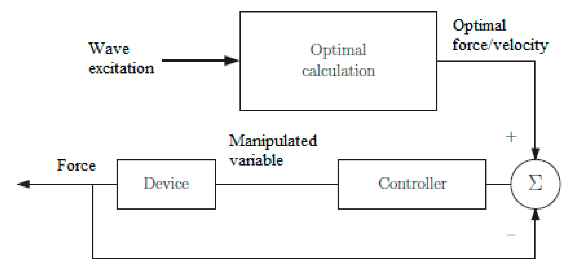
The control problem for the wave energy sector does not fit the classic description of control for other industries where control strategies involve the use of feedback (open loop, closed loop and set-point tracking) and forcing the system variables to a constant value. Instead, WEC control aims for maximization of captured energy while relying on feedforward control to generate optimal device velocity or PTO force setpoints (
Figure 7).
Optimal calculation involves the performance function of the form:
where
is the device velocity, and
is the exerted PTO force. To ease the understanding of how control maximizes this captured energy, we will start in
Section 3.1 with a simple analytical revision of the mean absorbed power and optimal control as originally defined in [
15] and further discussed in [
8], concluding with a discussion of why suboptimal control approaches are required before starting with the main topic for this paper, recent studies about different control strategies for wave energy converters.
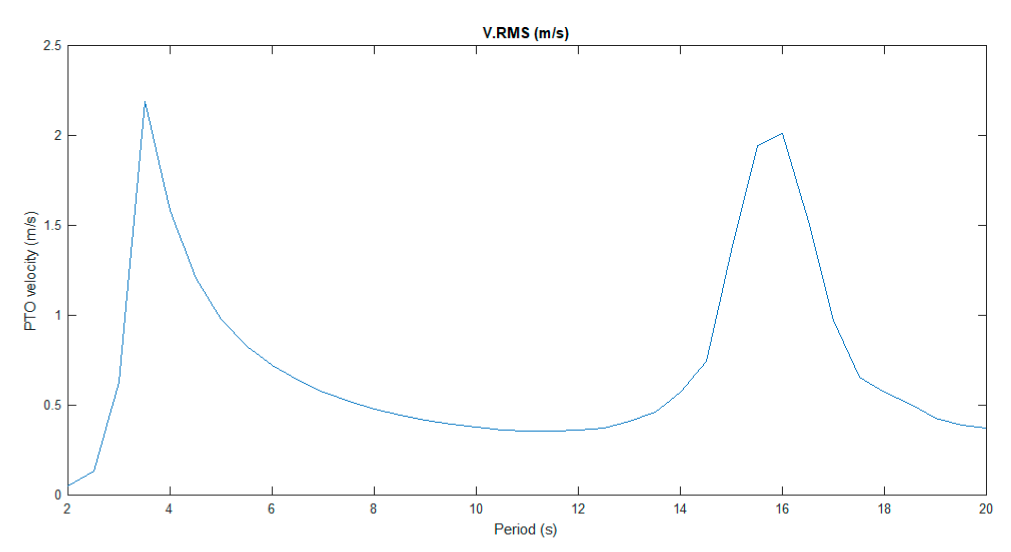
A good qualitative first approach to understand how to maximize the absorbed power is the concept of resonance. A system being excited at its natural frequency is described as resonant. When operating in resonance, the response amplitude is highest. Resonance does not usually occur naturally for wave energy converters that have a natural frequency higher (
Figure 8) than the power-rich frequency components of a typical wave spectrum, so we have to trick the system into resonance tuning the PTO damping and stiffness as needed, solving the impedance matching problem as we will explain later.
3.1. Numerical Modeling
For any WEC, the inertial force is balanced by the whole forces acting on the WEC. These forces are usually split into external loads, WEC-wave interaction (hydrostatic force, excitation load and radiation force) and reaction forces (caused by PTO, mooring or end-stop mechanism). Interaction between WECs (i.e., floater) and ocean waves is a high-order nonlinear process that can be simplified to linear equations for waves and small-amplitude device oscillation motions, which is acceptable throughout the device’s operational regime. This means that the superposition principle applies [
31].
The PTO system results in a complex nonlinear dynamic behavior. To keep the superposition principle valid, the PTO forces must be linearized. In this linear form, the PTO force is composed of two contributions [
32]: A force proportional to velocity (damper) and a force proportional to the displacement (spring). Mooring systems are often represented by a linear function of the captor displacement and the mooring spring stiffness. End-stop mechanism and other constrains (velocity or PTO force operational limits) are abrupt nonlinear forces which are usually not considered, given the complexity of a nonlinear approach for wave energy conversion. Instead, the optimum method of achieving an acceptable displacement amplitude is to increase the PTO damping until the body has the maximum allowance displacement [
33].
In [
8], M. Alves obtains the mean absorbed power assuming linearity and sinusoidal waves for a heave motion wave energy converter as:
where
is the wave frequency,
is the excitation force, m is the total inertia of the captor, A is the added mass,
is the hydrostatic spring stiffness,
is the PTO mechanical spring,
is the mooring spring stiffness,
R is the radiation damping,
is the PTO damping,
is the intrinsic impedance and
is the PTO impedance.
An alternative, yet equivalent, formulation considers the force-to-velocity model of a WEC in the frequency domain [
15] as,
where
,
, and
represent the Fourier transform of the velocity v(t), excitation force f
ex(t) and control force f
pto(t), respectively.
is the intrinsic impedance in the frequency domain of the system as
where
is the radiation damping (real and even) and
is the frequency-dependent added mass, often replaced by its high-frequency asymptote m∞.
The model in (4) allows the derivation of conditions for optimal energy absorption assuming a linear approach, and the intuitive design of the energy-maximizing controller in the frequency domain [
15] as
The choice of ZPTO as in (5) is referred to as optimal, reactive or complex conjugate control which is the solution to the so-called impedance-matching problem. Technically, reactive control refers only to the fact that the PTO reactance must cancel the inherent reactance. However, the PTO resistance and the hydrodynamic resistance must also be equal. Thus, complex-conjugate control is a more accurate description since it refers to the fact that the optimum PTO impedance equals the complex conjugate of the intrinsic impedance.
The result in (5) has a number of relevant implications [
34]:
The result is frequency dependent, implying a great optimization difficulty for irregular seas containing a mixture of frequencies.
Future knowledge of the excitation force may be required. While this knowledge is straightforward for regular waves, it is more complex for irregular seas.
Since force and velocity can have opposite signs, the PTO may need to supply power for some parts of the sinusoidal cycle.
The optimal control takes no constrains into consideration; it is more than likely a real system will have velocity and displacement constrains.
Nevertheless, delivering optimal control may be infeasible due to the associated excessive motions and loads in extreme waves. Hence, alternative suboptimal control schemes have been implemented, which include physical constraints on the motions, forces and power rating of the device. While a lot of discussion and different approaches can be found over the recent years for sub-optimal control solutions, we have classified most of them according to the nomenclature that most commonly appears—damping, reactive, latching and model predictive control.
3.2. Damping Control
A widely studied approach to avoid the difficulties in the implementation of the feedback control of the WECs is known in the literature as linear damping of the PTO, also called passive loading [
35] or resistive [
36], a suboptimal approach where the instantaneous value of the PTO force is linearly proportional to the oscillating body speed, that is to say
where
Bpto > 0 is the PTO damping coefficient. This methodology does not require a prediction of the excitation force, thus making it a simple strategy to implement. In fact, it is the one we can usually find in the demonstrators or pre-commercial devices currently deployed around the world. Conventionally, it only requires knowing the instantaneous value of the PTO velocity, for which measurement instruments are usually available in the market.
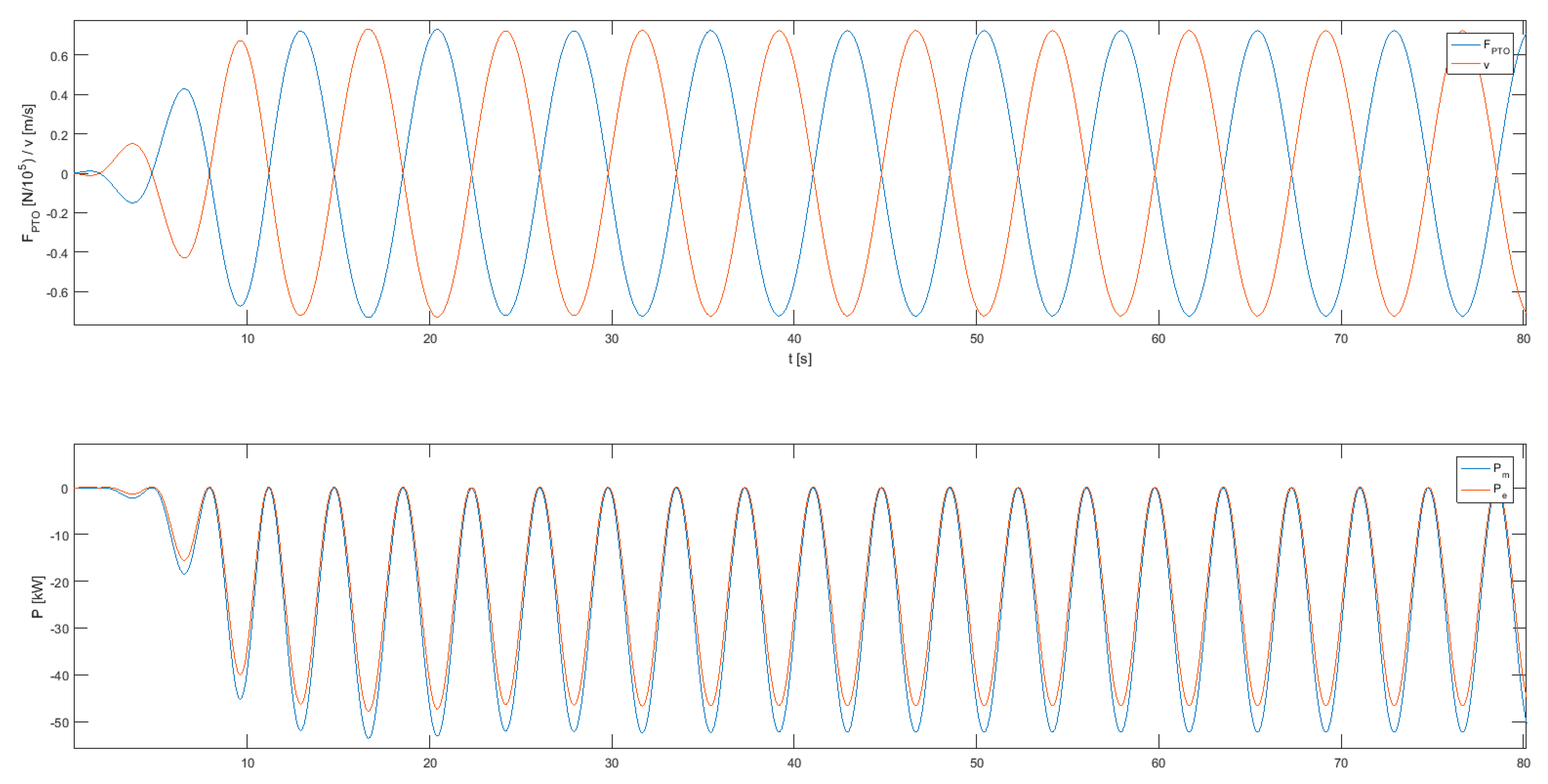
Figure 9 shows a simulation example in WECSIM [
30] for Reference Model 3 using damping control; the electric power (Pe) is always negative, Pe < 0, so the machine does not need to return energy at any point of the oscillating cycle to maximize the energy output in resonance operation.
Damping control, however, provides a much smaller amount of power absorbed when compared to other strategies such as reactive control [
37], as we will see in the next section, and the linear relationship between the speed and the force of the PTO, when it is a straightforward relation, may not be easy to implement without using any feedback control. In addition, the optimal value of the PTO damping, which is the value of
Bpto that maximizes the instantaneous power absorbed, can be easily calculated for regular waves. However, in practice, where the incident wave is irregular (defined by the wave spectrum),
Bpto is more difficult to calculate because of the changes in the spectral components of the incident wave which are not constant over time, so a real time feedback control for a time-varying damping value is required.
Therefore, we can distinguish between a real time-varying damping control and a constant (or passive) damping control. First generation WEC control is based on damping strategies with constant values for Bpto. This particular strategy is still very common in recent WEC prototypes by technology developers (given the simplicity of implementation).
3.2.1. Constant Damping Control
The work [
38] presents a PTO force via constant damping coefficient applied to compare the power conversion performances of three WEC devices modelled in a computational fluid dynamic software (CFD) model based on a 1/50 scale heaving point absorber WEC. Results from this article quantify crucial hydrodynamic parameters for the three devices, revealing a prominent affection of the device amplitude response in free motion without PTO. When PTO is included under effect of regular and irregular waves, the joint effects of geometry and PTO damping on the power absorption are very significant.
Experimental evidence with CECO device (a floating point absorber) with different linear damping coefficients is shown in [
39] with the following conclusions: (a) optimal PTO damping coefficients for low-energy irregular waves are higher than for high-energy regular waves, and (b) wave conditions affect significantly the optimal damping coefficients.
3.2.2. Time-Varying Damping Control
Passive damping control is analyzed and compared in [
35] with a real-time passive control (PC) based on the Hilbert–Huang transform (HHT). For this solution the damping coefficient is time-varying and tuned instantaneously, based on the frequency of the excitation force. This solution adds a grade of complexity to damping control, since it is required that excitation force be known. The results of this study prove that the proposed solution with real-time calibration of the damping coefficient improves from 21% to 65% the results that a conventional damping control strategy can obtain.
An experimental solution to calibrate the optimum damping coefficients has been presented in [
40], based on tank testing experiments on the power performance of a bottom hinged oscillating wave surge converter (OWSC) for regular and irregular waves with damping control, testing different damping coefficients for different wave conditions. The best damping coefficient based on performance was obtained. In this study it is concluded that there are no differences between linear or non-linear strategies in relation to the amount of energy absorbed, but nonlinear strategies have better stability and a broader damping range.
Damping control is electronically implemented in a solid-state relay (SSR) with pulse-width modulation (PWM) in [
38]. The objective for this analysis is to mimic analog current flow and compare it with a nonlinear model predictive control (NMPC). It is concluded that peak values of absorbed power and the capture width greatly improve, compared with passive damping strategy.
3.3. Reactive Control
Reactive control is often misleading in the literature and can be confused with complex conjugate control. As the differences between these definitions were already explained in
Section 3.1, for clarity reasons, we will keep “reactive control” as it can be usually found in the literature, but a new term such as “sub-optimal reactive control” should be used, as it is done in [
41]. These control strategies usually involve the tuning of both PTO resistance and reactance (
Bpto and
Kpto), taking into account constrains such as PTO power rating or displacement limits, adjusting the resistance of the PTO to avoid non-linear approaches [
33]. Therefore, we will need to consider the generic approach to a PTO characterization as explained in
Section 3.1.
where
is the stiffness coefficient, and
x(
t) is the displacement in the PTO. This kind of control when implemented in demo prototypes usually employs a tabular approach to alleviate the computational constrains required to calculate optimum values in real time. Hence, sub-optimal values for damping and stiffness coefficients are pre-calculated with an optimization algorithm to be stored in tables. For this reason, this particular technique is prone to modelling errors requiring a reanalysis of the constant values after a certain testing period.
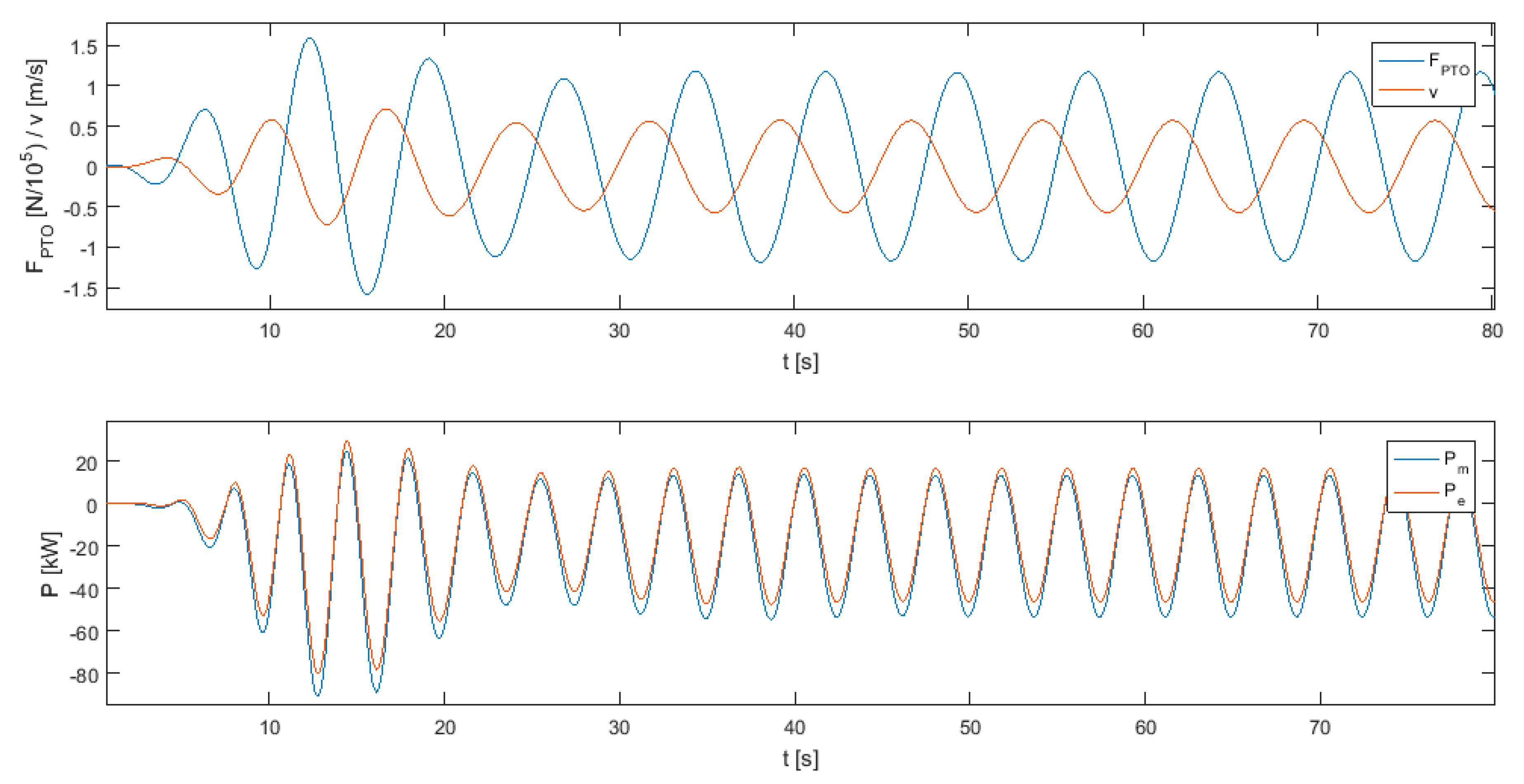
Figure 10 shows a simulation in WECSIM for Reference Model 3 [
29] using reactive control. The electric power (Pe) varies between positive and negative values, so the PTO needs to switch from motor to generator mode and vice versa at least two times for every oscillation cycle. This kind of mode switching is commonly called “4-quadrant control” and is not obtainable within the time constrains for all of the available typologies of PTOs in the market. Reactive power is a back and forth exchange between the PTO and the oscillating body and does not contribute to the facility energy production. This energy may be supplied by any hydraulic, compressed-air, thermal, chemical, kinetic, electrostatic, electromagnetic storage source [
42] or the electrical grid. The biggest disadvantage of reactive strategies comes from the reactive energy exchange process. This process does not suppose an electrical energy gain, but it is subject to dissipative energy loss processes. The magnitude of these losses can negatively affect the overall efficiency of the device.
Energy storage requirements for the reactive power are analyzed in [
41] based on a time-domain approach. These storage systems facilitate the exchange of reactive energy and can help to decrease the associated losses, so they are a critical element of the system to maximize the power absorption.
The performance of a floating heaving-only point absorber is analyzed in [
43]. The objective is to maximize the wave energy absorption by actively controlling damping and stiffness parameters on the basis of a linear model in the frequency domain. The study concludes with a comparison of the results with similarly validated studies.
Reinforcement learning methodologies are studied in [
44]. Calculating the optimum reactive control variables by means of a Q-learning algorithm, the model is able to maximize the energy absorbed for each sea state.
3.4. Latching/Unlatching
Firstly suggested in [
45], the latching control is based on achieving the resonance of the WEC through a clamping system, fixing the device during a certain part of the wave oscillation cycle [
46]. When the device is released, the control of the device is usually governed by a linear damping as in
Section 3.2. This way, the device presents resonance operation without need of reactive power control. However, some energy needs to be drawn from an external source in order to activate the clamping system when the device velocity is null. The critical point for this control strategy is the calculation of the latching-unlatching time periods. Latching control avoids the two-way energy transfer and the associated energy dissipation that characterize reactive control, so a wider spectrum of PTO systems operating only in generator mode can be used under this control strategy.
Setting as base case scenario the passive damping control strategy in [
47], the performance improvement when latching control strategy is applied was quantified. The results show that the capture width increases by 70% and the optimal damping coefficient decreases by 60%.
An economic approach was made with different latching control strategies assessed for the WEC in [
48], including an interesting comparison with passive damping control. Results are based on the simulated performance of the WEC using regular monochromatic waves, revealing similar annual energy production for constant damping when compared with suboptimal latching, 201 and 197 MWh/yr, respectively. Optimal latching shows the best results with a 45% increase over the annual energy production, 286 MWh/yr.
3.5. Model Predictive Control
Due to its ability to deal with linear and non-linear models, together with the system constrains and real time evaluation of future behavior, model predictive control (MPC) is a widely used and analyzed strategy in the industry [
49], and it should not be different for WECs. MPC solutions can handle the physical constraints present for any WEC technology and the non-causal optimal control solution.
However, the problem of maximizing WEC energy requires an important modification over the regular approach in the objective function of the MPC, resulting in a potentially non-convex optimization problem. Given the benefits and growing understanding of these algorithms, this strategy has become the most common control research topic in recent years. MPC maximizes the energy absorption, applying at each time step the optimum force to achieve resonance over a future time horizon, as firstly defined in [
50].
As a starting point, [
51] presents results of a comparison between MPC control and classical (complex-conjugate control) methods for a Linear Permanent Magnet (LPMG) PTO controlled by a machine side back-to-back actuator. It is concluded that complex-conjugate control when applied to real world solutions shows to be inefficient in maximizing the power absorption from the ocean waves.
Presented as an improvement to reactive control, a predictive strategy is analyzed in [
52] where a neural network trained with machine learning is used to predict future waves (height and period), affecting the WEC and optimizing in real time the relevant parameters for the wave energy absorption (PTO stiffness coefficient and PTO damping coefficient). The algorithm does not present any improvements over similar state-of-the-art reactive control solutions in relation with the absorbed power, but it solves associated control inaccuracies from laboratory calibration and enables the controller to be adaptative to variations in the machine response caused by ageing.
In a similar way for a heaving point-absorber, a neural network is employed to forecast the short-term wave height and period in [
53] to implement real-time adaptative latching control. This work presents some results comparing the differences of absorbed power for a particular wave scenario with and without control.
An innovative MPC solution is proposed in [
54]. Named as robust model predictive control (R-MPC), it combines a predictive controller considering PTO constrains, ensuring maximum power absorption while being realistic, and an innovative model to solve some parametric uncertainties and model mismatches.
An interesting approach to control strategies for 3-degree of freedom WECs is presented in [
55] and compared with classical heave-only WECs. Presenting a parametric MPC, it optimizes independently the pitch-surge and heave motion. Numerical algorithms are employed to find the optimal conditions and results. In this work, several numerical tests are conducted for regular and irregular waves. The presented results reveal a great improvement in absorbed power over heavy-only WECs. Contrary to these results, in [
56] A. Korde states that near-optimal control for pitch-surge motions are not significant for wave energy absorption when compared to heave motion which is presented as the dominant contributor to power absorption.
A hybrid MPC strategy is presented in [
57], constrains are applied to PTO damping and damping force for a two-body WEC. A Mixed-integer Quadratic Programming (MIQP) problem is proposed to obtain the maximum power absorption. Results from this problem are compared with other MPC solutions and classical models for an irregular wave scenario.
Future wave frequency prediction is used in [
58] using a Fuzzy Logic controller to determine the optimum PTO damping and stiffness coefficients in real time. The proposed solution combines some regular tuning techniques with an innovative slow tuning methodology.
Fatigue, reliability and survivability controlled by MPC are analyzed in [
36]. The results show a trade-off between maximized electrical power and the necessary dimensions for the WEC to resist large loads and fatigue periods. These results are also compared with conventional reactive control, where MPC improves the average annual energy production by 29%.
3.6. Others
This category includes any mixed or innovative control strategies that do not clearly fit into any of the categories presented above.
A genetic algorithm is used to optimize truncated power series along with the geometry for nonlinear WECs in [
59]. It enables higher energy harvesting without large motions and less dependence of reactive power as a result.
A so-called Adaptive Parameter Estimation (APE) is proposed in [
60]. The algorithm updates in real time several WEC model parameters such as the radiation and excitation force coefficients, combining the benefits associated with optimal control (maximum energy output) and APE dealing with any of the model parameter variation.
In [
61] a new power take-off technique is proposed for oscillating wave surge WECs. The main innovation is to avoid any kind of braking system while keeping the amplitude within the specified range. Then, the results are compared with constant damping control, showing the benefits of the new proposed control system.
A new controller which is a variation for the complex conjugate through impedance matching in the time-domain is proposed in [
62,
63]. The main benefit for the proposed control lies in that it does not need a wave prediction or measurement. It is novel in that it is a feedback strategy with a multi-resonant generator strategy, decomposing the control problem into multiple sub-problems with independent single-frequency controllers. The solution is based on the spectral decomposition of the measurement signal which is employed to construct the optimal solution.
Stochastic control derived from optimal control for heave-only point absorbers considering force constrains is analyzed in [
64]. Results indicate performance close to optimal in terms of mean absorbed power.
A crosscutting solution can be found for a cabin-suspended catamaran with a motion control system in [
65]. The main objective is to minimize the heave velocity in the cabin, but a secondary measured result of interest for this review is the power absorption from incoming waves which can then be used as an energy vector for different applications, such as feeding auxiliary systems or driving the main engines.
4. Conclusions and Further Research
Since the mean absorbed power for any WEC is frequency dependent, maximum power absorption is achieved in resonance operation when the natural frequency of the WEC matches the wave frequency, causing the excitation force. We can force the WEC into resonance with different control strategies tuning the PTO damping and stiffens constants (Bpto and Kpto). In this article, we have classified different wave energy technologies based on different criteria commonly used in the literature. Optimal control strategy (complex conjugate control) based on solving the impedance matching problem is impractical for implementation, given the need for future knowledge of the excitation force in irregular waves and the absence of constrains in force and speed for the PTO. Hence, suboptimal control techniques are required, such as damping, reactive (misleading definition which should be revised to suboptimal reactive), latching, MPC and other novelty control ideas.
Wave Energy Technologies are still far from the commercialization point. Only a few successful demonstration projects can be found all over the world and even less when we try to find grid connected projects. Several regulatory, social, economic, environmental and technological barriers need to be addressed from different stakeholders at the same time to perceive an effective pulling action. Control strategies is one of the main technological topics to be discussed. Great efforts have been made over the years in developing effective suboptimal solutions for WECs.
Damping control, usually constant damping control, has been (and still is) the best approach for technology developers willing to test an industrial scale WEC device, given the simplicity of implementation and the safety of operation. Safety is not a minor issue for industrial scale marine devices. Large forces and motions provided by optimal control and top suboptimal approaches could exceed the operational limits of prototype devices fabricated by shipyards and/or associated industries still unfamiliar with WEC technology.
Reactive control is the natural evolution from damping control, presenting an affordable tabular approach for any WEC prototype being deployed for a demonstration phase. Calibration of PTO constants based on simulations or previous experiences do not represent a challenge to the current state of art, although this kind of control strategy requires a PTO capable of switching from motor to generator mode multiple times in a single wave oscillation.
Latching control solves the PTO limitation of reactive control, but it requires an additional clamping mechanism to be installed and energized in the WEC, generating extra costs while also lowering the reliability. Offshore equipment, especially mechanical pieces, are prone to failure because of the extreme salinity ambient. Even well protected (marinization) pieces require a yearly basis maintenance to avoid failures.
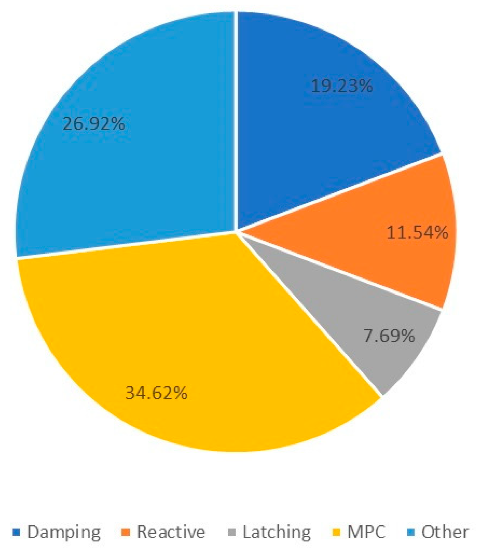
MPC solutions represent the best approach to optimal control. Enabling excitation force prediction applies at each time step the optimum PTO force for maximum energy absorption while still considering constrains (non-linear models). MPC has been found to be the most interesting topic among the scientific community (
Figure 11) over the recent years, given the good results presented in different articles. This is due to the growing experience in simulated and tank-testing environments, the incremental available advances in computational capacity and the improved expertise with environments based on neural networks. Nevertheless, the complexity of implementation and absence of industry scale demonstration projects disfavored MPC solutions for WEC technology developers. MPC strategies can become a WEC technology enabler in the near future. Maximizing the energy reliability while maintaining equipment costs will result in overall reduction of LCOE, along with the support from different stakeholders. Caring about the other WEC barriers previously presented will result in a market competitive renewable energy technology.


