Article

Power Curve-Fitting Control Method with Temperature Compensation and Fast-Response for All-Metal Domestic Induction Heating Systems

1
Department of Electrical and Computer Engineering, Sungkyunkwan University, Suwon 16419, Korea
2
Intelligent Mechatronics Research Center, Korea Electronics Technology Institute (KETI), Bucheon 14502, Korea
*
Author to whom correspondence should be addressed.
Energies 2019, 12(15), 2915; https://doi.org/10.3390/en12152915
Submission received: 13 May 2019 / Revised: 22 July 2019 / Accepted: 26 July 2019 / Published: 29 July 2019
(This article belongs to the Section F: Electrical Engineering)

Abstract

:
Typical domestic induction cooktops can only heat ferromagnetic pots/vessels. However, to increase the availability and marketability of induction heating (IH) cooktop products, heating techniques for all types of metallic pots (i.e., created from metals such as aluminum, copper, and stainless steel) are required. To satisfy the requirements of induction cooktops, this paper proposes the design of an all-metal domestic IH system that can heat any type of metallic pot while considering the temperature variation of the working-coil. A control algorithm using a power curve-fitting method (CFM) is presented to quickly respond to load parameter variations in the IH. In addition, the CFM control algorithm is established to compensate for the power reference value by reflecting the increase in the working-coil temperature during the heating of the non-ferromagnetic pot. To evaluate the performance of the proposed system, the control algorithm strategy and experimental results based on a 3.2 kW all-metal IH cooktop are presented.

1. Introduction

With the increasing awareness of stability and environmental issues, domestic cooktops that employ induction heating (IH) methods have gained popularity worldwide. Compared to the conventional gas and electric stoves, IH cooking technology offers advantages such as improved conversion efficiency, ease of cleaning, low noise, rapid heating, and high reliability. Conventional IH techniques for heating the ferromagnetic pots described above are well known, and many manufacturers have already commercialized products by applying different technologies. However, a typical induction cooktop that is used in a home can only heat ferromagnetic pots/vessels [1,2]. In particular, conventional induction cooktops exhibit a disadvantage as non-ferromagnetic pots (made of aluminum, copper, and stainless steel), which are widely used in homes, cannot be heated, and only specific pots where the entire pot or only the bottom surface is made of a ferromagnetic material can be heated [3,4,5]. Because non-ferromagnetic pots have very low relative permeability and resistivity, it is difficult to heat them with conventional IH technology. Further, the design of an operation method for heating only non-ferromagnetic pots is limited to heating ferromagnetic pots [6,7,8]. Therefore, to increase the availability and marketability of induction cooktops, recent studies have focused on the development of an all-metal IH cooktop that is capable of heating any type of metallic pots.
The main technique for the IH of non-ferromagnetic pots is the compensation of low relative permeability and resistivity values. Previous research on this technology can be summarized as follows. (1) A step-up/down converter topology for heating ferromagnetic and non-ferromagnetic pots by varying the DC-link voltage was proposed in References [6,7]. (2) An induction cooktop was developed in Reference [7] to heat low-resistivity pots using a double-layer working-coil structure with dual-resonant circuits. However, the studies presented in References [6,7,8] focused primarily on designing the hardware required to implement all-metal IH systems, and any experimental results based on the application of the pot material and the size-identification method as well as the control algorithm were not presented. (3) A half-bridge series resonant converter (HB-SRC) topology with two selective resonant capacitors and dual-resonant load circuits was proposed in References [9,10] to heat various pots with a resonant frequency changing scheme. In References [9,10], the research results on the identification of pot materials using electric power differences were presented; however, specific pot material and size-identification algorithms, control response, and actual identification experiments were not verified. (4) A HB-SRC operating in a third-harmonic operation mode was proposed in Reference [11] to heat various pots with a resonant frequency changing scheme. This proposed system demonstrated the advantages of minimizing the number of components in comparison with other all-metal IH topologies. However, there is a drawback that the equivalent input voltage was three times smaller than the conventional first-harmonic operation mode. Based on these studies, Panasonic Corp. developed an all-metal IH cooktop product by applying an international patent for a triplex series load resonant high-frequency technology operating at three times the switching frequency [9,10,11]. This cooktop utilized the power limit control method to prevent overvoltage/overcurrent based on minimum operating frequency and maximum voltage and current values. This conventional trip unit is not suitable because the non-ferromagnetic pot has a relatively high quality (Q) factor; therefore, it can cause overvoltage/overcurrent even with a marginal frequency variation [12,13]. Further, there is a disadvantage that the control response is slow in a situation where the load parameter changes owing to the placement of a foreign object or a misalignment between the center of the working-coil and the pot. In particular, for the safety of users, no-load identification experiments using standard sticks and foreign objects recommended by the International Electrotechnical Commission (IEC) Standard 60335-2-9 are essential [14]; however, the results of these studies were not presented in References [6,7,8,9,10,11,12,13]. Moreover, when heating non-ferromagnetic pots, the working-coil temperature rises owing to the relatively large current, which causes a change in the parameter value of the working-coil [15,16]. Therefore, there is a requirement for a compensation control algorithm that always demonstrates stable output characteristics regardless of the power variation due to the temperature rise in the working-coil.
In this paper, an all-metal domestic IH system consisting of a control algorithm using a power curve-fitting method (CFM) is proposed to overcome the drawbacks of previous research. The proposed system can heat both non-ferromagnetic and ferromagnetic pots by applying an optimal resonant frequency changing method using HB-SRC with two selective resonant capacitors. In addition, the proposed control method can identify whether the IH power value is within the normal range by monitoring in real time at the operating frequency. The load modeling was performed after analyzing the parameters of the pot material and the variation values according to the misalignment between the center of the working-coil and the pot; moreover, it was based on the designed working-coils for the all-metal IH systems. The temperature of the working-coil was analyzed by performing mathematical analyses and actual experiments, and the temperature variation was reflected in the control algorithm. Using the temperature information and CFM modeling, the compensation control algorithms were designed to ensure stable output characteristics regardless of the variations in the power, which can occur owing to an increase in the temperature of the working-coil or with changes in the load condition. The detailed design and control algorithm strategy of the proposed power CFM modeling method are described in this paper, and the performance of the proposed system was verified based on experimental results obtained for a 3.2 kW all-metal IH cooktop.

2. Design Consideration for Proposed All-Metal IH System

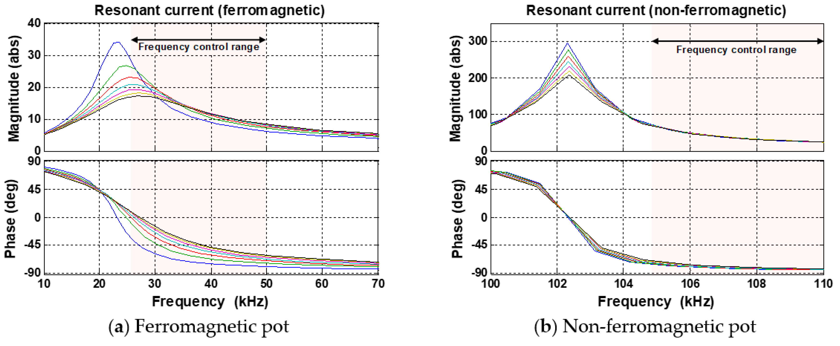
2.1. Considerations for Induction Heating of Non-Ferromagnetic Pot

The output power generated by the actual IH system is presented by the relationship between the resistance and the current as follows:
P = k ( N I 1 ) 2 ρ μ r 2 π f
where k, N, ρ, μr, and f are constants that are related to the permeability, number of turns of the working-coil, resistivity of the material, relative permeability, and frequency of the current flowing in the working-coil, respectively. Figure 1 shows equivalent resistance (Req) and inductance (Leq) according to the variation of frequency measured by an LCR meter using the standard cast-iron and aluminum pots that are placed on the working-coil [14]. Electrical characteristics of representative ferromagnetic and non-ferromagnetic pots, such as cast-iron and aluminum pots are indicated in Table 1. Because the non-ferromagnetic pot has a very low Req, the switching frequency should be increased [17,18,19]. Figure 2 shows the variation of the IH power as the frequency varies, and the operation of the non-ferromagnetic pot in the high-frequency region. However, these conditions increase the resistance of the working-coil owing to the skin effect and proximity effect [15]. In addition, when the non-ferromagnetic pot is heated, the loss increases because of the large free-wheeling current caused by the phase delay, and a relatively large current is required to generate the same electric power as the ferromagnetic pot because of the low resistance. These problems lead to an increased temperature in the working-coil and ferrite core owing to iron and copper losses [20,21,22]. In addition, the efficiency of the IH system decreases because the permeability is drastically reduced [16]. In particular, as shown in Figure 2, the non-ferromagnetic pot is relatively more sensitive to the output power characteristics in terms of frequency variation because it has a relatively high Q-factor compared to the ferromagnetic pot [17]. Therefore, regardless of the power variation due to the temperature rise in the working-coil and the fluctuation of the load condition, there is a requirement for a compensation control algorithm demonstrating output characteristics that are always stable. Furthermore, for practical all-metal IH implementation, control algorithms that can quickly identify the pot material, size, and position are required.

2.2. Prototype Design for All-Metal IH System

To implement an all-metal domestic IH system, this study focused on the design and control algorithm of the HB-SRC topology with two selective resonant capacitors and dual-resonant load circuits while considering the operating frequency range for IH of ferromagnetic and non-ferromagnetic pots. From the above-mentioned concept, the overall diagram of the proposed all-metal domestic IH system is illustrated in Figure 3. The proposed system consisted of a power-factor correction (PFC) circuit using a two-phase interleaved boost converter, a HB-SRC with two selective resonant capacitors, and a working-coil. The load of the all-metal IH system consists of a working-coil and a pot as the object to be heated.
Table 2 indicates the electrical specifications of the all-metal domestic IH system, along with the working-coil and resonant capacitor parameter values. The input voltage of the HB-SRC was 380 Vdc, which was the output voltage of the PFC circuit; the power consumption range was 3.2 kW while heating the ferromagnetic pot, and the non-ferromagnetic pot heating mode was limited to 2.6 kW to prevent the overcurrent by considering the low Req. The two selective resonant capacitor configurations of the dual-resonant load circuit were determined by the relay on/off state. Figure 4 shows the simulation waveforms of the current and phase of the heating modes of the ferromagnetic and non-ferromagnetic pots, according to the frequency variation considering the parameter values. The shaded area of each figure shows the operating frequency range of each mode and each line is indicated by the change of the impedance value. The inverter could always be operated with zero-voltage switching (ZVS) in the frequency control range, and the inverter current value at full load was approximately 19 Arms and 50 Arms, respectively, which was similar to the calculated IH power.

3. Control Strategy of the Proposed All-Metal IH System

This section proposes an all-metal IH system and control algorithm using CFM modeling to overcome the problems associated with the conventional design and control method. The load modeling for the proposed system was performed after analyzing the parameters of the pot material and the variability according to the misalignment between the center of the working-coil and the pot, based on the designed working-coils for the all-metal IH system. The temperature of the working-coil was analyzed by performing mathematical analyses and actual experiments, and the temperature variation was reflected in the control algorithm.

3.1. Load Analysis and Operating Modes of the Proposed System

The load on an all-metal domestic IH system is a cooking pot/vessel that is widely used in homes. Pot materials are generally classified as cast-iron, aluminum pots, and double-bottom pots with iron powder applied to the bottom. In addition, in the case of IH cooktops, the load conditions owing to user mistakes such as misalignment between the pot and working-coil, no-load condition without the pot, and the presence of foreign object loads, such as spoons, should be considered. Table 3 depicts the bottom diameters of different pots and the amount of water during the IH test based on IEC standard 60335-2-9 [14].
Figure 5 shows the IH power according to the frequency variation analyzed by performing simulations based on the parameter value at each load condition. From the IH power curve, the double-bottom pot can operate in both non-ferromagnetic and ferromagnetic heating areas. When the double-bottom pot is operated in the ferromagnetic heating area under the maximum-power condition, the phase delay of the voltage and current is large, and a relatively high current flow occurs. However, when operating in the non-ferromagnetic heating area, it is advantageous to consider the double-bottom pot as non-ferromagnetic because the phase delay decreases and a relatively low current flow occurs. A ferromagnetic pot with a diameter of approximately 90 mm caused an overcurrent to flow owing to the low Req and phase delay when operating at a maximum power of 3.2 kW in the ZVS region. Therefore, a control technique that limits the maximum power by distinguishing the bottom area of the pot was required, and the mini cast-iron pot limited the maximum power to 1.1 kW. Foreign objects such as sticks and spoons that confirm to the IEC standard were considered to be similar to the no-load conditions operating at less than 50 W in most frequency ranges. However, because the overcurrent flowed in the vicinity of the resonant frequency when a foreign object was placed or under the no-load condition, a reliable and quick-response algorithm for identifying the load condition was required.
The power unit of the proposed all-metal domestic IH system has three operating modes, as shown in Figure 5 and Figure 6, according to the pot-type and heating mode. Detailed descriptions of the operating modes are as follows:
(1)
Mode I: In this mode, the HB-SRC soft-starts at a high switching frequency to identify the material and sizes of the pots. In the initial operation, the relay is always in the off-state, as shown in Figure 6a, and the power is safely controlled by detecting foreign objects and no-load conditions. Once the material and size of the pot are identified, the HB-SRC will proceed to the next appropriate heating mode.
(2)
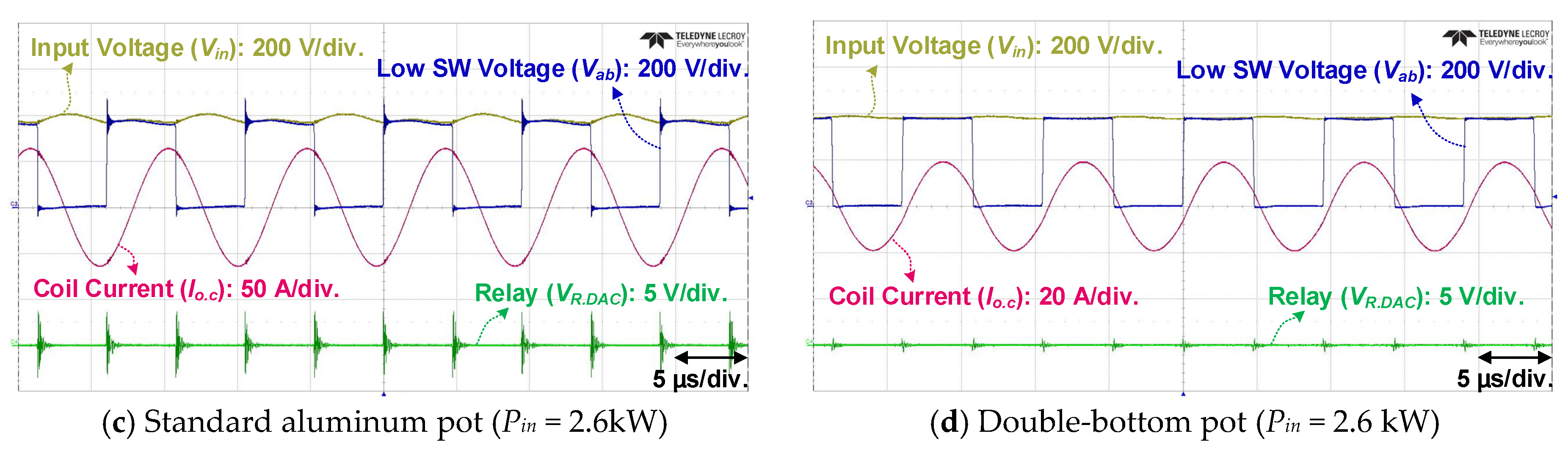
Mode II: This mode is the operating mode for heating the non-ferromagnetic pots. The relay maintains the off-state and operates in the high frequency range above 100 kHz, as shown in Figure 5. Mode II limits the maximum power to 2.6 kW because the non-ferromagnetic pots are applied as loads.
(3)
Mode III: In this operating mode, the ferromagnetic pots are heated. When the ferromagnetic pot is identified from Mode I, the relay changes to the on-state and enters Mode III, as shown in Figure 6b. The operating switching frequency is less than 50 kHz and the maximum power is 3.2 kW.
Details of the pot-type identification algorithm and control strategy are described in the next section.

3.2. Proposed Power Curve-Fitting Control Method

As mentioned previously, because the non-ferromagnetic pot has a relatively high Q-factor, it can cause overvoltage and overcurrent, even with a slight frequency variation, as shown in Figure 7. Therefore, the design of a control algorithm that is reliable and has a rapid response is required to improve performance and stability. The conventional control algorithm of the IH cooktop system sets the minimum frequency and maximum power limit, as shown in Figure 8a, for preventing overvoltage and overcurrent; however, this method demonstrates the disadvantage that when the load condition is changed during the heating of the pot, the time until power cut-off is delayed. In the non-ferromagnetic pot heating mode, an increase in the current stress of the device can lead to a system malfunction. To resolve this problem, a control algorithm using the power CFM modeling method was applied to the proposed all-metal domestic IH system. The power CFM modeling derived the third-order polynomial by using Excel for the IH power values according to the frequency variation that was obtained by performing mathematical analyses and actual experiments [23]. The power curve of the derived third-order polynomial is set to the power limit value by adjusting the fitting-ratio, as shown in Figure 8b. The proposed control method can identify whether the IH power value is within the normal range by monitoring in real time at the operating frequency point. Therefore, it is a control method that is sensitive to load parameter variations and additionally, the control sensitivity can be easily changed by adjusting the fitting-ratio. Because each pot has a different IH power depending on the frequency, the pot material and size should be identified early, and the power CFM modeling formula applied accordingly. The pot identification area shown in Figure 8b is depicted in detail in Figure 9; This figure shows the initial IH power for each pot, and the frequency range while operating in Mode I for soft-start and pot detection. The material and size are identified using the initial power difference of the IH loads, and then operated in the proper heating operation mode. Because the relay is in the off-state in Mode I, if the ferromagnetic pots are frequency controlled to follow the IH target power, the operating frequency will exceed the resonant frequency and shift to the zero-current switching (ZCS) region, causing switch stress owing to the reverse recovery current [24]. Therefore, when a soft-start is started at 140 kHz and it is identified as a ferromagnetic pot, the relay is immediately turned on and the switching frequency directly decreases to 90 kHz, which is the initial soft-start point of the ferromagnetic pots. Because the IH power of the mini cast-iron pots is similar to no-load at the initial frequency, it is identified at approximately 115 kHz, where the power difference becomes clear, as shown in Figure 9. Non-ferromagnetic pots such as the double-bottom pot or aluminum pot operate in Mode I, and they then enter Mode II with the relay still in the off-state. When the pot moves from the center of the working-coil to the outside during the heating process after the pot type is identified, Req decreases and the control algorithm using power CFM modeling decreases the operating frequency to follow the target power. At this time, when the actual heating power is lower than the power of the CFM curve at the operating frequency, it is reset to the initial operation at Mode I. The power is cut off when the load condition does not enter the normal category until the reset count is repeated for approximately 1 min. Furthermore, when the no-load condition occurs or the standard stick is heated, the foreign-object detection (FOD) function can be performed because the operating frequency is reduced to follow the target power, and eventually reaches the power-limit curve and the algorithm is reset.
The standard aluminum pot and the double-bottom pot operating in the non-ferromagnetic mode differ from each other in the rising slope of the power curve according to frequency, as shown in Figure 10a; therefore, the CFM modeling is applied by deriving the respective third-order polynomial. The mathematically analyzed CFM modeling of aluminum pots is given by
P I H   =   0.0992 f 3 +   18.132 f 2   7983.3 f   +   527763 ,
where PIH and f are the input power of the system during IH and the operating frequency of the inverter, respectively. In addition, the CFM modeling of double-bottom pots is calculated as follows
P I H   =   0.0919 f 3 +   36.389 f 2   4815.7 f   +   213169 .
In the case of a cast-iron pot operating in the ferromagnetic mode, even if the pot diameter changes, the slopes of the power curves are similar and only the power value is different; therefore, as shown in Figure 10b, the CFM modeling is applied with the same third-order polynomial and different fitting-ratio. The CFM modeling of the cast-iron pot can be calculated as
P I H   =   0.2649 f 3 +   35.943 f 2   1637.4 f   +   25505 .
The values of the fitting-ratio of the cast iron pot with diameters of 210 mm and 90 mm were 0.8 and 0.3, respectively.

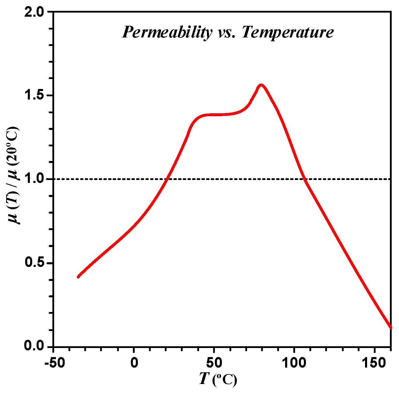
3.3. Working-Coil Temperature Compensation Algorithm

As mentioned above, for non-ferromagnetic pots such as aluminum, the operating frequency and number of turns of the working-coil should be increased. However, these conditions increase the resistance of the coil owing to the skin effect and proximity effect. Consequently, the problem of working-coil temperature rise occurs because a relatively high current flows, resulting in the heating of the non-ferromagnetic pot [16]. The rise in the Litz wire resistance of the working-coil and the rise in temperature owing to the copper loss of the ferrite eventually lead to a decrease in permeability [25]. Figure 11 shows the variation of the initial permeability with temperature relative to 20 °C in a ferrite. Generally, ferrite increases the permeability during the initial temperature rise; however, the permeability decreases rapidly from a certain temperature and loses magnetism when it reaches the Curie temperature [26]. Therefore, because the magnetic flux density is proportional to the magnetic permeability, the reduction of the magnetic flux density reduces the induced electromotive force (EMF). Consequently, the amount of eddy current is reduced, which leads to a decrease in IH efficiency [27]. When the IH efficiency is reduced, even if the pot is heated normally at the center of the working-coil, the power CFM limit is reached and the system power is cut off. Therefore, it is necessary to consider and compensate for the decrease in IH power that results from the increase in the working-coil temperature.
Figure 12 is a photograph of the working-coil temperature measured by a thermal imager during the pot heating process in the designed all-metal IH cooktop system. Both heating conditions were measured at full-load conditions for 5 min, and the detailed specifications are indicated in Table 4. When the non-ferromagnetic pot is heated, the working-coil temperature rises and the ferrite temperature on the bottom surface also increases, as shown in Figure 12b, and it saturates at approximately 140 °C. Therefore, when the working-coil temperature rises, the fitting-ratio of the power CFM limit curve should be appropriately changed according to the temperature variation. When heating a ferromagnetic pot, the working-coil temperature records a maximum of 50 °C, as shown in Figure 12a. However, in the case where residual heat remains in the working-coil after heating the non-ferromagnetic pot or when the pot is replaced with a ferromagnetic material during the heating of the non-ferromagnetic pot, because the power CFM limit curve is distorted, a temperature compensation process considering the working-coil temperature is required.
Figure 13 shows the variation in the power curve according to the frequency as the working-coil temperature rises when heating non-ferromagnetic pots that were analyzed by performing actual IH experiments. During heating at a maximum power of 2.6 kW, the power decreased as the working-coil temperature rose, and frequency control was required to achieve the target power. Thus, the power CFM limit curve should decrease corresponding to the decrease in actual power. The instantaneous temperature of the working-coil was measured by attaching a thermocouple below the surface, and the temperature information was reflected in the control algorithm to adjust the ratio of the initial pot detection and power CFM limit. Therefore, it was possible to implement a control algorithm that operates adaptively regardless of the load parameter values, which fluctuate as the working-coil temperature rises. Figure 14 shows the control algorithm flow chart of the all-metal domestic IH system in which the working-coil temperature compensation is reflected in the CFM modeling. The fitting-ratio of the CFM control for each heating mode was set in consideration of various parameters such as the position, material and size of the pots in order to prevent misidentification of the pots.

4. Experimental Results

To verify the proposed all-metal domestic IH system, experiments were performed using a 3.2 kW prototype, as shown in Figure 15. The changing operating frequency, signal of the relay status, and power reference were checked by the oscilloscope using the digital-to-analog converter (DAC) function of the digital signal processor (DSP).

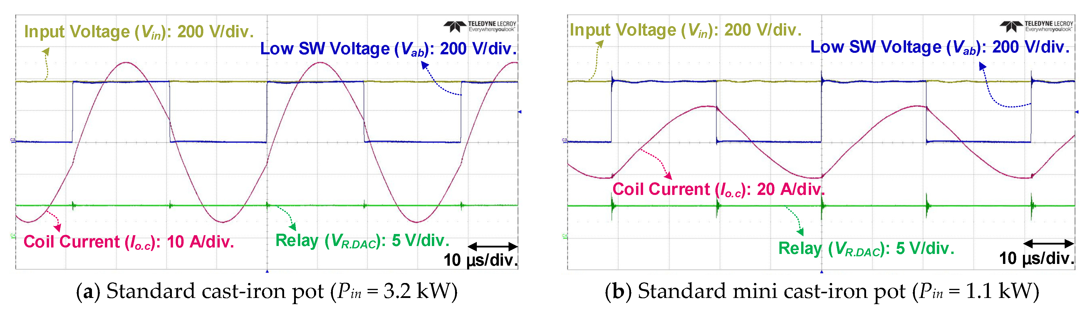
4.1. Pot IH and Boiling-Speed Experiment

The performance of PFC circuit, which was the input of the proposed system, was verified at 3.2 kW output power condition using the grid voltage of 220 Vac, as shown in Figure 16a. Figure 16b shows a plot of the efficiency and power factor, which demonstrates a high efficiency (over 97.3%) in all load regions, and the maximum efficiency and PF were 98.1% and 0.99, respectively. Figure 16 shows the main waveforms obtained during IH under full-load conditions. Figure 17a,b show the heating waveforms of the ferromagnetic pots, and the relay is in the on-state and while operating in Mode III. Figure 17c,d show the heating waveforms of non-ferromagnetic pots while operating in Mode II.
Table 5 indicates the results of the boiling-speed test and IH efficiency performed corresponding to the IEC standard 60335-2-9 of water quantity listed in Table 3 [14]. The test conditions are as follows: (1) The pot was allowed to stand at room temperature (25 °C) for more than 4 h before heating. (2) The IH was operated in the full-load condition according to the pot-type. (3) The heating process started at a temperature of 25 °C and the time was measured until the water boiled (Δ75 K). The overall efficiency of the all-metal IH system considering the power conversion efficiency of the PFC circuit was calculated by deriving the input/output energy as follows
E i n   =   P I H    ×   B o i l i n g s p e e d    ×    1 3600    [ W h ] ,
E o u t   =   Q u a n t i t y   o f   w a t e r    ×   Δ T    ×    C [ W h ] ,
where PIH and C are the input power of the system during IH and the specific heat of water (joule/gram °C), respectively.

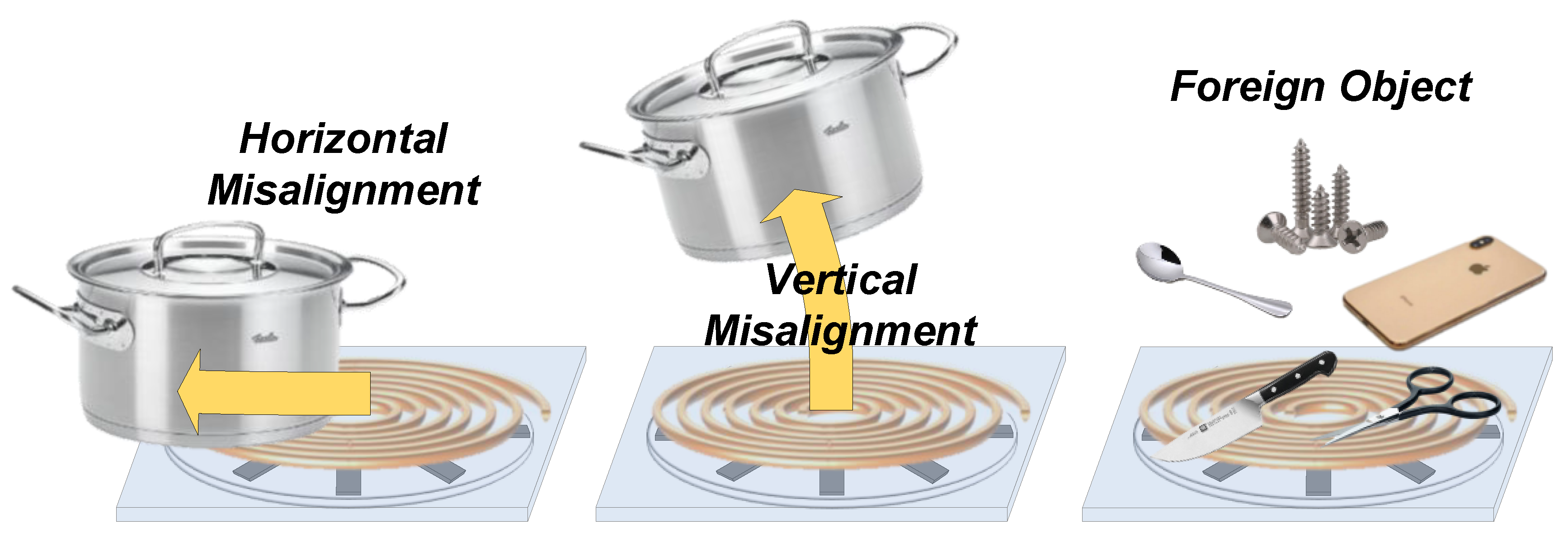
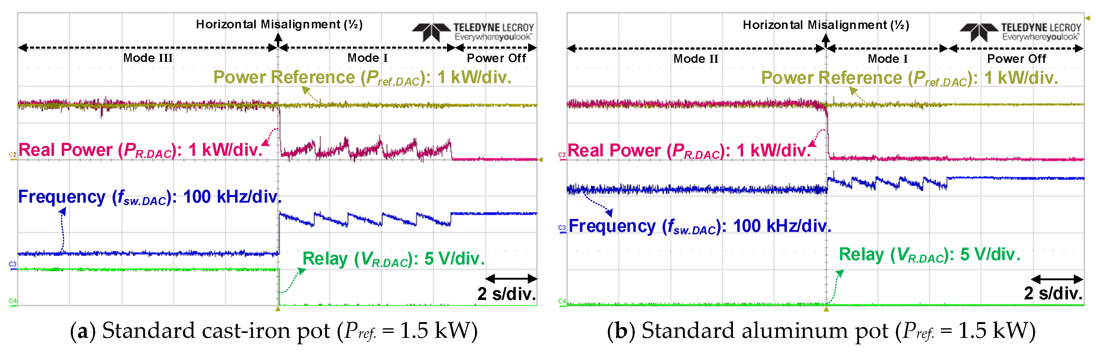
4.2. Misalignment Experiment between Pot and Working-Coil

The normal IH process of the pots should stop when the pots move vertically up (disappear) or are horizontally misaligned. To verify whether the system was stopped stably in these situations, the experiment using the proposed control algorithm was performed. The control algorithm of the proposed system set the fitting-ratio of the power CFM limit for each pot to cut-off the power in the case of misalignment that was more than half the distance from the center of the working-coil. Figure 18 shows the waveform when the pot was misaligned horizontally to approximately halfway from the center of the working-coil during IH. The values of the power reference, real power, operating frequency, and relay signal were measured with an oscilloscope using the DAC function of the DSP. Figure 18a shows the waveform of the misalignment case during the heating of the ferromagnetic pot. When the pot was misaligned during heating, the control algorithm was reset to perform the pot-detection function of Mode I. At this time, the number of resets to Mode I was set to five times in order to facilitate the experimental verification. Figure 18b shows the main waveform when the non-ferromagnetic pot was misaligned. Owing to the difference in the value of Req for the ferromagnetic and non-ferromagnetic pots, the real power rise slope is different during reset. During the reset period, if the pot did not return to the center position of the working-coil, the power was eventually cut-off. Figure 19 shows the waveform obtained when the pot was moved up (vertically) from the working-coil during IH. In this case, because there was no heating object on the working-coil, it changed to no-load condition during IH.

4.3. Pot Replacement and Detection Experiment during IH

This section presents the verification of the normal operation of the pot detection and initial startup when the pot was replaced with different types of materials and sizes during IH. In addition, to confirm the temperature compensation of the control algorithm, the experimental verification was performed during the rise in working-coil temperature. During the experiment, the working-coil was air cooled with a 5 W fan. Figure 20 shows waveforms obtained when the pot type was changed while the working-coil temperature was increased to more than 130 °C by heating the non-ferromagnetic pot for 5 min. In Mode II, when the non-ferromagnetic pot moved vertically during heating, it entered Mode I and performed pot detection and identification. Figure 20a shows that when the ferromagnetic pot was placed on the working-coil while the control algorithm repeated the reset in Mode I, the pot-type was identified and heated in Mode III. Figure 20b shows the experimental waveform obtained when the pot was replaced with a non-ferromagnetic pot during the heating of the ferromagnetic pot. As in the previous case, the increase in the working-coil temperature was reflected in the algorithm so that the pot detection and identification were performed without problems, and the real power reached the power-reference value, and the aluminum pot was normally heated in Mode II.

5. Conclusions

In this paper, the design and implementation of an all-metal domestic IH system that can heat both ferromagnetic and non-ferromagnetic pots while considering the temperature variation of the working-coil was presented. The load modeling for the proposed system was performed after analyzing the parameters of the pot material and the variation in values according to the misalignment between the center of the working-coil and the pot, based on the working-coils that were designed to heat any kind of pots. To improve the performance and stability of the all-metal domestic IH systems, a control algorithm using a power CFM modeling was proposed to quickly respond to load variations. For improved user safety, the FOD and misalignment identification functions based on the IEC standard were applied to the proposed novel control scheme. The proposed 3.2 kW all-metal IH cooktop including the control algorithm was verified by performing experiments under various load conditions. The proposed cooktop system can contribute to the successful commercialization of all-metal IHs by satisfying their various requirements.

Author Contributions

Conceptualization, S.M.P.; Data curation, S.M.P. and E.J.; Formal analysis, S.M.P.; Investigation, S.M.P. and E.J.; Project administration, B.K.L.; Software, S.M.P. and E.J.; Supervision, B.K.L.; Validation, S.M.P. and D.J.; Visualization, S.M.P. and D.J.; Writing–original draft, S.M.P. and B.K.L.; Writing–review & editing, S.M.P. and B.K.L.

Funding

This work was supported by “Human Resources Program in Energy Technology” of the Korea Institute of Energy Technology Evaluation and Planning (KETEP), granted financial resource from the Ministry of Trade, Industry & Energy, Republic of Korea. (No. 20184030202190).

Conflicts of Interest

The authors declare no conflicts of interest.

References

  1. Acero, J.; Burdio, J.M.; Barragan, L.A.; Navarro, D.; Alonso, R.; Garcia, J.R.; Monterde, F.; Hernande, P.; Llorente, S.; Garde, I. Domestic induction heating appliances: An overview of recent research. In Proceedings of the 2008 Twenty-Third Annual IEEE Applied Power Electronics Conference and Exposition, Austin, TX, USA, 24–28 February 2008; pp. 39–47. [Google Scholar]
  2. Koertzen, H.W.; van Wyk, J.D.; Ferreira, J.A. Design of the half bridge series resonant converters for induction cooking. In Proceedings of the Power Electronics Specialist Conference (PESC ‘95), Atlanta, GA, USA, 18–22 June 1995; pp. 729–735. [Google Scholar]
  3. Dawson, F.P.; Jain, P. A comparison of load commutated inverter Systems for Induction Heating and Melting Applications. IEEE Trans. Power Electron. 1991, 6, 430–441. [Google Scholar] [CrossRef]
  4. Park, S.M.; Jang, E.; Joo, D.; Lee, B.K. Power curve-fitting control method with temperature compensation for all-metal induction heating systems. In Proceedings of the 2019 IEEE Applied Power Electronics Conference and Exposition (APEC), Anaheim, CA, USA, 17–21 March 2019; pp. 3388–3393. [Google Scholar]
  5. Esteve, V.; Jordán, J.; Sanchis-Kilders, E.; Dede, E.J.; Maset, E.; Ejea, J.B.; Ferreres, A. Improving the reliability of series resonant inverters for induction heating applications. IEEE Trans. Ind. Electron. 2014, 61, 2564–2572. [Google Scholar] [CrossRef]
  6. Shoji, H.; Uruno, J.; Isogao, M. Buck-boost-full-bridge inverter for all metal induction heating cookers. IEEJ J. Ind. Appl. 2016, 5, 339–346. [Google Scholar] [CrossRef]
  7. Ahmed, N.A.; Nakaoka, M. Boost-half-bridge edge resonant soft switching PWM high-frequency inverter for consumer induction heating appliances. IEEE Proc. Electr. Power Appl. 2006, 153, 932–938. [Google Scholar] [CrossRef]
  8. Tanaka, T. A new induction cooking range for heating any kind of metal vessels. IEEE Trans. Consum. Electron. 1989, 35, 635–641. [Google Scholar] [CrossRef]
  9. Sadakata, H.; Fujita, A.; Sumiyoshi, S.; Omori, H.; Saha, B.; Ahmed, T.; Nakaoka, M. Latest practical developments of triplex series load resonant frequency operated high frequency inverter for induction-heated low resistivity metallic appliances in consumer built-in cooktops. In Proceedings of the 2010 Twenty-Fifth Annual IEEE Applied Power Electronics Conference and Exposition (APEC), Palm Springs, CA, USA, 21–25 February 2010; pp. 1825–1832. [Google Scholar]
  10. Ogiwara, H.; Nakaoka, M. ZCS high frequency inverter using SIT for induction heating applications. IEEE Proc. Electr. Power Appl. 2003, 150, 185–192. [Google Scholar] [CrossRef]
  11. Millan, I.; Burdio, J.M.; Acero, J.; Lucia, O.; Llorente, S. Series resonant inverter with selective harmonic operation applied to all-metal domestic induction heating. IET Power Electron. 2011, 4, 587–592. [Google Scholar] [CrossRef]
  12. Lucia, O.; Maussion, P.; Dede, E.J.; Burdio, J.M. Induction heating technology and its applications: Past developments, current technology, and future challenges. IEEE Trans. Ind. Electron. 2014, 61, 2509–2520. [Google Scholar] [CrossRef]
  13. Han, W.; Chau, K.T.; Jiang, C.; Liu, W. All-metal domestic induction heating using single-frequency double-layer coils. IEEE Trans. Magn. 2018, 54, 1–5. [Google Scholar]
  14. Safety Standards for Household Electrical Products: IEC 60335-2-9; IEC: Geneva, Switzerland, 2019.
  15. Acero, J.; Burdio, J.M.; Barragan, L.A. Frequency-dependent resistance in litz-wire planar windings for all-metal domestic induction heating appliances. In Proceedings of the Twentieth Annual IEEE Applied Power Electronics Conference and Exposition (APEC), Austin, TX, USA, 6–10 March 2005. [Google Scholar]
  16. Sergeant, P.; Hectors, D.; Dupre, L.; van Reusel, K. Thermal analysis of magnetic shields for induction heating. IET Electr. Power Appl. 2009, 3, 543–550. [Google Scholar] [CrossRef] [Green Version]
  17. Acero, J.; Alonso, R.; Burdio, J.M.; Barragan, L.A.; Puyal, D. Analytical equivalent impedance for a planar circular induction heating system. IEEE Trans. Magn. 2006, 42, 84–86. [Google Scholar] [CrossRef]
  18. Simha, D.; Sadhu, P.K.; Pal, N. Computation of Induction and AC Resistance of a Twisted Litz-Wire for High Frequency Induction Cooker. In Proceedings of the 2010 International Conference on Industrial Electronics, Control and Robotics (IECR 2010), Orissa, India, 27–29 December 2010; pp. 85–90. [Google Scholar]
  19. Lope, I.; Acero, J.; Carretero, C. Analysis and optimization of the efficiency of induction heating applications with litz-Wire planar and solenoidal coils. IEEE Trans. Power Electron. 2016, 31, 5089–5101. [Google Scholar] [CrossRef]
  20. Bhat, A.K.S. Analysis and design of a modified series resonant converter. IEEE Trans. Power Electron. 1993, 8, 423–430. [Google Scholar] [CrossRef]
  21. Burnham, J.; Buritz, R.S. Factors affecting corona inception levels of coils insulated with Kapton and Nomex. In Proceedings of the Conference on Electrical Insulation & Dielectric Phenomena, Pocono Manor, PA, USA, 12–14 October 1970; pp. 222–227. [Google Scholar]
  22. Sarnago, H.; Lucía, O.; Burdio, J.M. A Versatile Resonant Tank Identification Methodology for Induction Heating Systems. IEEE Trans. Power Electron. 2018, 33, 1897–1901. [Google Scholar] [CrossRef]
  23. Robinson, M.P.; Clegg, J. Improved determination of Q-factor and resonant frequency by a quadratic curve-fitting method. IEEE Trans. Electromagn. Compat. 2005, 47, 399–402. [Google Scholar] [CrossRef]
  24. Martinez, W.; Noah, M.; Imaoka, J. Reverse-recovery current reduction in a ZCS boost converter with saturable inductors using nanocrystalline core materials. In Proceedings of the 2016 18th European Conference on Power Electronics and Applications, Karlsruhe, Germany, 5–9 September 2016. [Google Scholar]
  25. Gerber, S.S. Performance of high-frequency high-flux magnetic cores at cryogenic temperatures. In Proceedings of the 2002 37th Intersociety Energy Conversion Engineering Conference, Washington, DC, USA, 29–31 July 2002. [Google Scholar]
  26. Niedra, J.M. Design Considerations for High Temperature Power Inductors; NASA: Washington, DC, USA, 2005.
  27. Patidar, B.; Hussain, M.M.; Jha, S.K.; Dikshit, B.; Sharma, A. Modelling and experimental demonstration of a litz coil-based high-temperature induction heating system for melting application. IET Electr. Power Appl. 2018, 12, 161–168. [Google Scholar] [CrossRef]
Figure 1. Parametric values of the pot according to frequency variation.
Energies 12 02915 g001
Figure 2. Induction heating operation area according to pot material.
Energies 12 02915 g002
Figure 3. Configuration of the proposed all-metal induction heating (IH) system.
Energies 12 02915 g003
Figure 4. Current and phase of inverter according to frequency variation.
Energies 12 02915 g004
Figure 5. Input power curve according to pot type and frequency variation.
Energies 12 02915 g005
Figure 6. Operating modes of the proposed all-metal IH system.
Energies 12 02915 g006
Figure 7. Safety considerations for induction heating.
Energies 12 02915 g007
Figure 8. Control algorithm strategy of the IH system.
Energies 12 02915 g008
Figure 9. Power curve according to pot-type at frequencies ranging from 140 kHz to 115 kHz.
Energies 12 02915 g009
Figure 10. Power limit curve using curve-fitting method (CFM) modeling by pot-type.
Energies 12 02915 g010
Figure 11. Variation of the initial permeability with temperature.
Energies 12 02915 g011
Figure 12. Working-coil temperature according to the pot material during IH.
Energies 12 02915 g012
Figure 13. Variation in IH power curve owing to rising working-coil temperature.
Energies 12 02915 g013
Figure 14. Control algorithm flow chart for the proposed all-metal domestic IH system.
Energies 12 02915 g014
Figure 15. Prototype of the proposed all-metal domestic IH system.
Energies 12 02915 g015
Figure 16. Waveforms of power-factor correction (PFC) circuit.
Energies 12 02915 g016
Figure 17. IH experimental waveform of the pot under full load conditions.
Energies 12 02915 g017aEnergies 12 02915 g017b
Figure 18. Waveforms of horizontal misalignment for pots during IH.
Energies 12 02915 g018
Figure 19. Waveforms of vertical displacement for pots during IH.
Energies 12 02915 g019
Figure 20. Waveforms obtained for pot-replacement and detection experiments.
Energies 12 02915 g020
Table 1. Electrical characteristics according to material.
ParametersFerromagnetic and High ResistivityNon-Ferromagnetic and Low Resistivity
Cast-IronSUS430AluminumCopper
Electrical Resistivity (ρ (μΩm))0.170.720.0270.017
Relative Permeability (μs)10005001.000020.999994
Previously Developed IH Cooktop××
Remarks: applicable, × not applicable.
Table 2. Specification of all-metal IH system.
All-Metal IH System SpecificationsResonant Network
ParametersValue (Unit)ParametersValue (Unit)
FerromagneticNon-Ferromagnetic
Operating Power400–3200 (W)400–2600 (W)Working-Coil Layer3 (Layer)
Operating Frequency25–51 (kHz)105–110 (kHz)Working-Coil Turns39 (turn)
Maximum Coil Current19 (Arms)50 (Arms)Capacitance for Fe300 (nF)
Maximum Coil Voltage490 (Vpeak)2500 (Vpeak)Capacitance for Al22 (nF)
Table 3. Pot type and amount of water for all-metal domestic IH system load.
Picture Energies 12 02915 i001 Energies 12 02915 i002 Energies 12 02915 i003 Energies 12 02915 i004 Energies 12 02915 i005
PotStandard cast-iron potStandard aluminum potDouble-bottom potStandard mini cast-iron potStandard stick or no-load condition
Diameter of Cooking Zone210 (mm)160 (mm)180 (mm)90 (mm)70 (mm)
Quantity of Water2 (L)1.5 (L)1.5 (L)0.6 (L)-
Table 4. Working-coil parameter value for all-metal IH system.
ParameterFerromagnetic Pot Non-Ferromagnetic Pot
Working-Coil Max. Temp. (°C)50 145
Maximum Coil Current (Arms)1950
Operating Frequency (kHz)28105
Table 5. Results of the proposed system for boiling-speed test and IH efficiency.
Pot-TypeDiameter of Cooking Zone (mm)Quantity of Water (L)Input Power (W)Boiling Speed (s)IH Efficiency (%)
Standard Cast-Iron2102320024187.05
Standard Mini Cast-Iron900.6110017283.51
Standard Aluminum1601.5260026671.28
Double-Bottom1801.5260021886.97

