Article

Decoupled Current Controller Based on Reduced Order Generalized Integrator for Three-Phase Grid-Connected VSCs in Distributed System

1
School of Electrical Engineering, Southeast University, Nanjing 210096, China
2
Department of Electrical Engineering, School of Automation, Nanjing University of Science and Technology, Nanjing 210094, China
*
Author to whom correspondence should be addressed.
Energies 2019, 12(12), 2426; https://doi.org/10.3390/en12122426
Submission received: 13 May 2019 / Revised: 11 June 2019 / Accepted: 21 June 2019 / Published: 24 June 2019
(This article belongs to the Special Issue Design and Control of Power Converters 2019)

Abstract

:
Grid-connected voltage source converters (GC-VSCs) are used for interfacing the distributed power generation system (DPGS) to the utility grid. Performance of the current loop is a critical issue for these GC-VSCs. Recently, reduced order generalized integrator (ROGI)-based current controller is proposed, such that AC reference signal of positive or negative sequences can be separately tracked without steady-state error, which has the advantage of less computational burden. However, the cross-coupling within the ROGI-based current controller would deteriorate the transient response of the current loop. In this paper, a ROGI-based decoupled current controller is proposed to eliminate the coupling between α -axis and β -axis. Thus, the faster dynamic response performance can be achieved while maintaining the merits of ROGI-based current controller. An optimal gain parameter design method for the proposed current controller is presented to improve the stability and dynamic response speed of current loop. Simulation and experiments were performed in MATLAB/Simulink and TMS320C28346 DSP-based laboratory prototype respectively, which validated the proposed theoretical approach.

1. Introduction

In recent years, distributed power generation system (DPGS) has attracted increasing attention with the aggravation of global energy shortage and environmental issues [1,2,3,4,5]. A typical DPGS is shown in Figure 1; due to the intermittence of renewable energy sources (RESs) such as PV systems and wind turbines, energy storage systems (ESSs) based on battery and supercapacitor are used to suppress power fluctuations, which improves the reliability and quality of power supply. Moreover, integrating the electric energy generated by RESs into the power grid is an important way to improve power generation efficiency. As the typical power electronic interfaces between DPGS and power grid, GC-VSCs have been intensively studied [6,7]. In the grid-connected mode, the voltage and frequency at the point of common coupling are dictated by strong power grid, the GC-VSC is controlled to behave as current-controlled converter. Active and reactive power regulation are performed by changing the grid-connected output current [8,9]. Therefore, accurate and fast control of the grid-connected current is one of the most critical technologies, which directly affects the power quality [8,9,10,11,12,13].
Various research has focused on current control of GC-VSCs [4,6,7,8,9,10,11,12,14,15,16,17,18,19,20,21,22,23,24,25], among which the most widely studied control method is PI controller [17,19,23,26], which effectively guarantees excellent tracking of AC reference signals and fast dynamic response speed, since AC signals become DC signals through Park transformation and PI controller could produce infinite gain for DC signals [16,17,26]. Nevertheless, d-axis and q-axis current cross-coupling, resulting from the Park transformation, is proportional to the interested control frequency. Actually, the modulation and sampling delay tend to aggravate the coupling and even deteriorate stability of the current loop [17,26]. In addition, resonant controllers are widely used in current loop regulation of GC-VSCs. Proportional-resonant (PR) and vector proportional-integral (VPI) controllers are, respectively, equivalent to conventional PI and complex-vectors PI (cPI) regulators, which are implemented in a positive and negative sequence SRF simultaneously [17]. It assures perfectly tracking AC reference signals without steady-state errors for both sequences [5,6,7,9,12,14,15,18]. However, the negative-sequence term (i.e., j ω e ) of conjugated poles introduces two times control frequency fluctuation, bringing slower dynamic response and more severe cross-coupling [16,26]. Moreover, computational burden increases when multiple order harmonics need to be tracked simultaneously [21,22].
To overcome the disadvantage of the above controllers, some improved methods are proposed. The method of state-feedback decoupling is proposed in [16], which effectively reduces the axes cross-coupling and broadens the bandwidth of current loop. Nevertheless, the decoupling effectiveness could be affected by the time delay and the accuracy of parameter estimation. The alternative decoupling method based on cPI controller is less influenced by these two factors [17]. Thus, a better stability and a faster dynamic response speed of the current loop are achieved. However, the implementation of the aforementioned control algorithms is in SRF and the rotating frame transformation increases the computational burden and complexity. Simultaneously, the error of transformation calculation would emerge if the PLL is not sufficiently accurate [7,9,26]. Overall, a regulator with zero steady-state error in the stationary frame would have some certain advantages in terms of implementation [9,10,11,12]. ROGI-based current controller, which is named as PCI controller in [11,12], is proposed with the advantage of less computational burden and improving the bandwidth of harmonics control [21,25]. However, the cross-coupling within the ROGI-based current controller would deteriorate the transient response of the current loop. In addition, the stability of the current loop will decrease when the control frequency is relatively high [23].
In this paper, a ROGI-based decoupled current controller is proposed, which is capable of suppressing the cross-coupling and improving the dynamic response speed, while possessing the advantage of low computation burden and being convenient to implement. An optimal gain method for parameter tuning is also presented to maximize the stability of the current loop.
The paper is organized as follows. Coupling of ROGI-based current controller is analyzed in Section 2. Section 3 introduces the proposed ROGI-based decoupled current controller. Specially, the performance of the proposed controller is analyzed through closed-loop frequency response and mathematical derivation, and the optimal parameter design using the root locus is presented. The simulation and experimental results are provided to validate the theoretical approach in Section 4. Finally, Section 5 summarizes the work.

2. Coupling Analysis of ROGI-Based Current Controller

The ROGI is proposed in [21], its transfer function in the s-domain can be expressed as
G R O G I ( s ) = 1 s j ω e
where ω e is the fundamental frequency and “ / + ” denotes the positive/negative sequence. The implementation principle of ROGI is shown in Figure 2a.
A novel proportional complex integral (PCI) is derived from the principle that zero steady-state error can be achieved if the open-loop gain is infinity at the control frequency [10]. Thus, it can be written by,
G P C I ( s ) = k p + k i s j ω e
where k p is the proportional gain and k i is the integral gain. It is known from Equation (2) that the PCI controller is equivalent to ROGI-based current controller in [10,21]. For convenience, the PCI controller represents the ROGI-based current controller in this paper. The implementation principle of PCI is shown in Figure 2b, where it can be seen that PCI controller includes two k p · ω e coupling branches, which will deteriorate the transient response of the current loop. Besides, the coupling aggravates as the control frequency increases.
Figure 3 shows the diagram of PCI-based current closed-loop for GC-VSCs. G d s ( s ) = e s T d represents the digital control delay, which consists of one and a half sampling time delay [19], T d = 1 . 5 T s ( T s is the sampling cycle). For a more intuitive sense of the coupling, α -axis and β -axis current response with PCI controller is presented in Figure 4 when a step change occurs in reference current. The reference current i α β * decreases from 10 · e j ω e t to 0 at t = 0 . 04 s , where i α * = Re { i α β * } = 10· cos ( ω e t ) and i β * = Im { i α β * } = 10· sin ( ω e t ) . In Figure 4a,b, it can be seen that reference current changes in α -axis affects β -axis current, and vice versa. In addition, the coupling will increase with the rising of the control frequency.

3. The Proposed ROGI-Based Decoupled Current Controller

To suppress the axes-coupling in the PCI-based current loop. an effective decoupling method with ROGI-based decoupled current controller is proposed, which improves dynamic response performance of the current loop. For convenience, the proposed ROGI-based decoupled current controller is referred to as the D-PCI controller in the following section.

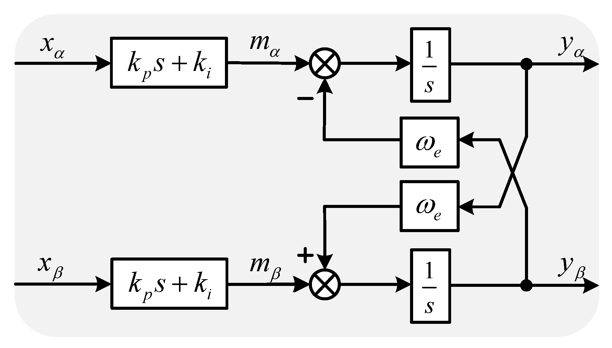
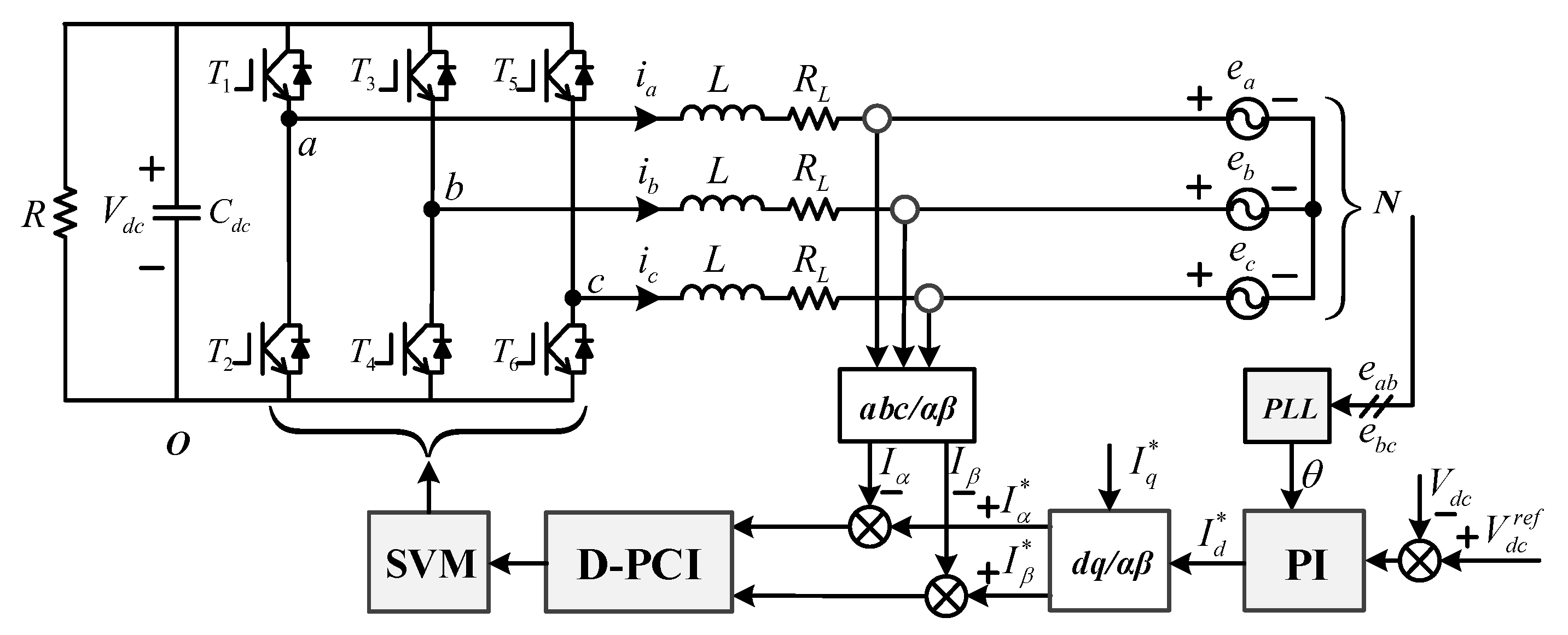
3.1. Structure of the D-PCI Controller

As shown in Figure 2b and the analysis of coupling, the key to effective decoupling is to remove the cross-coupling term k p · ω e . Thus, the structure of the proposed D-PCI current controller is shown in Figure 5. Thus, the transfer function of D-PCI can be expressed as
G D P C I ( s ) = k p + k i + j ω e k p s j ω e
Based on Equations (2) and (3), the Bode plot of PCI and D-PCI controllers tuned at ω e = 2· π ·50 rad/s (i.e., fundamental excitation frequency is 50 Hz) is shown in Figure 6. It can be seen that both PCI and D-PCI controllers achieve infinite gain at fundamental excitation frequency, which means that precise AC reference signal tracking can be realized. Moreover, D-PCI controller has superior performance in suppressing DC reference signal. The magnitude for D-PCI controller is −6.5 dB, while PCI controller is 27 dB.
Replacing the PCI with D-PCI in Figure 3, α -axis and β -axis current response with D-PCI controller is presented in Figure 7 when a step change occurs in reference current. In Figure 7a,b, it can be seen that, regardless of the control frequency, there is almost no coupling between the current of α -axis and β -axis.

3.2. Performance Analysis of the D-PCI Controller

From Figure 3 and Equation (3), the output current I α β can be derived as
I α β ( s ) = e s T d · ( k p s + k i ) ( s L + R L ) ( s j ω e ) + e s T d · ( k p s + k i ) I α β * ( s ) s j ω e ( s L + R L ) ( s j ω e ) + e s T d · ( k p s + k i ) e α β ( s )
where
G C L s s = ( k p s + k i ) · e s T d ( s j ω e ) s L + R L + ( k p s + k i ) · e s T d
is the transfer function between I α β ( s ) and I α β * ( s ) , and
G D L s ( s ) = s j ω e ( s L + R L ) ( s j ω e ) + e s T d · ( k p s + k i )
is the transfer function between I α β ( s ) and e α β ( s ) .
If the frequency of I α β * ( s ) (reference input signal) and e α β ( s ) (disturbance signal) is equal to ω e , i.e., s = j ω e , then G C L s ( j ω e ) = 1 and G D L s ( j ω e ) = 0 . It means that D-PCI controller can realize tracking of AC reference signals and suppress AC disturbance signals. Both closed-loop frequency response and mathematical derivation would be used to evaluate the steady-state tracking performance.
According to Equations (5) and (6), the closed-loop frequency response curves at different control frequencies are shown in Figure 8. The following conclusions can be drawn:
(1)
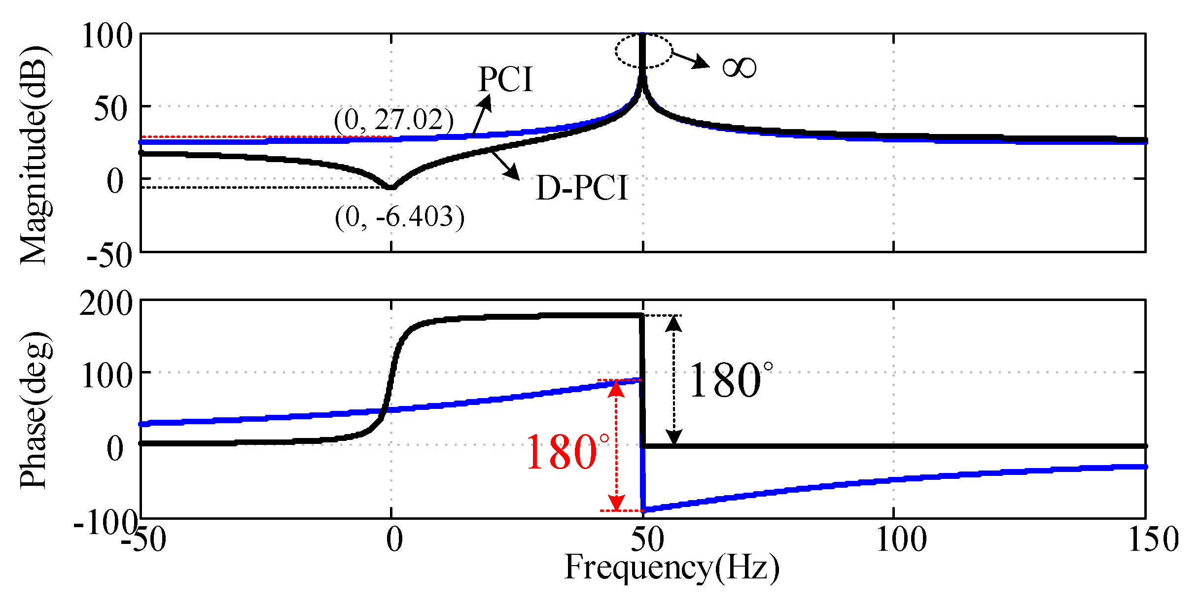
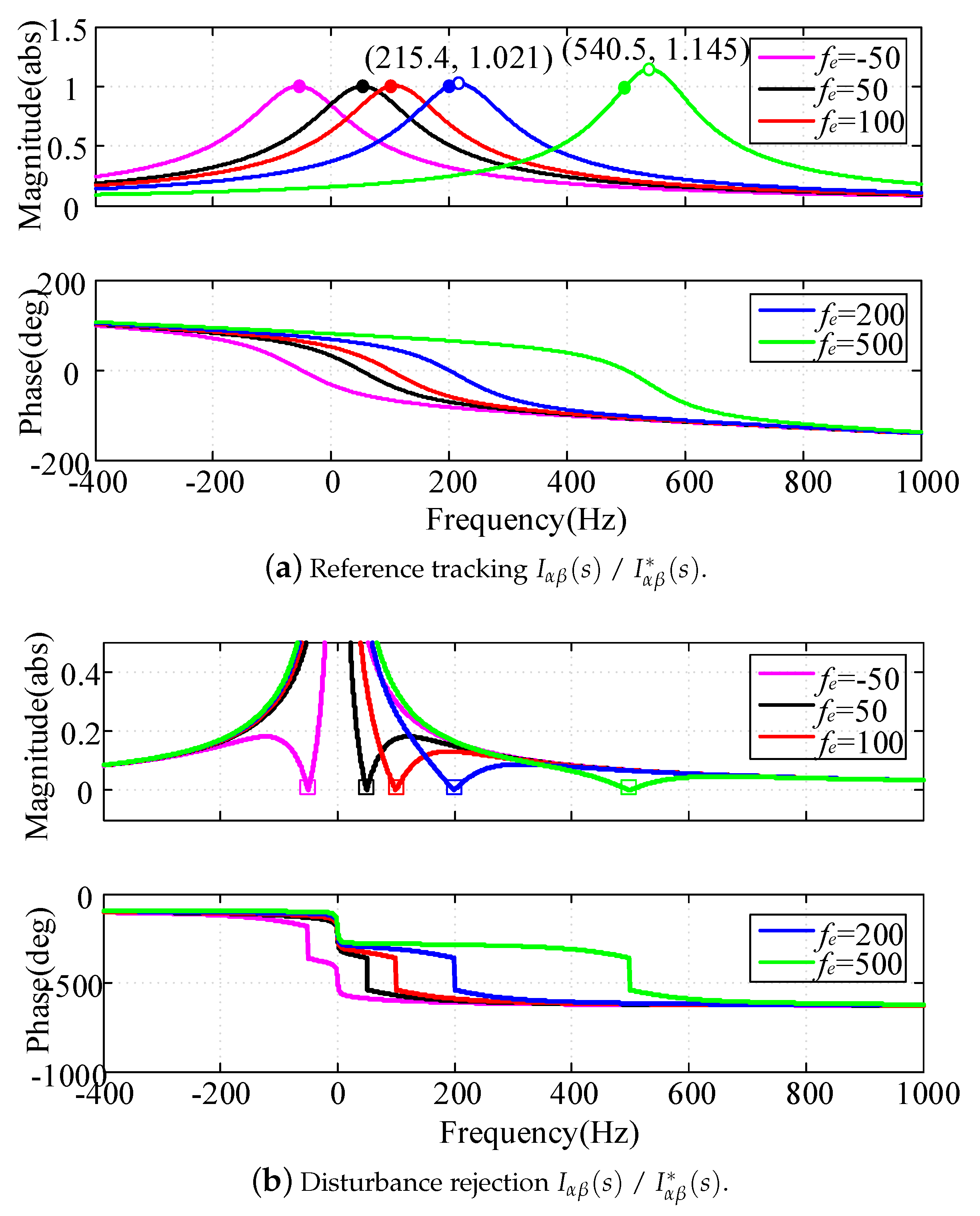
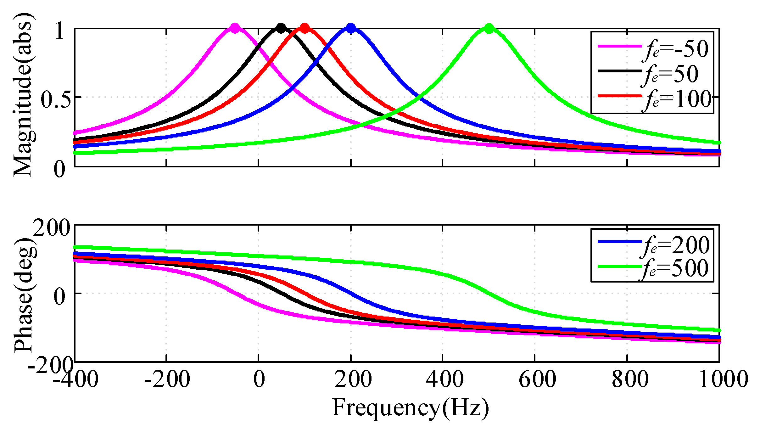
Since the controller provides infinite gain at the interested control frequency (−50 Hz, 50 Hz, 100 Hz, 200 Hz and 500 Hz), unity gain and 0 phase lag output current can be achieved, i.e., I α β ( s ) / I α β * ( s ) = 1 0 , the steady-state error is zero, as shown by “•” in Figure 8a.
(2)
As shown by “∘” in Figure 8a, a closed-loop anomalous peak (amplification phenomenon of output current) appears near the control frequency, and, as the control frequency increases, the peak value becomes larger, e.g., no obvious amplification appears at 50 Hz or 100 Hz, while the peak value is 1.02 (1.145) times of the unity gain at 215 Hz (540 Hz). It means that the closed-loop anomalous peak will aggravate the transient oscillation and increase the adjustment time and overshoot with the abrupt change of reference signal. Besides, if phase lock angle is inaccurate, the steady-state output current would be amplified.
(3)
As shown in Figure 8b, the disturbance signal at the interested control frequency is completely suppressed, i.e., the magnitude is zero (as shown by “□”).
The delay compensation method is used to suppress the closed-loop anomalous peak, and Figure 9 shows the closed-loop frequency response after delay compensation. It can be seen that the unity gain and 0 phase lag output current are achieved at the interested control frequencies, and the closed-loop anomalous peak is completely excluded, as shown by “•” in Figure 9.
From the analysis of delay compensation above, the influence of time delay can be ignored. According to the internal model control (IMC) method [13], to cancel the pole of G P L s ( s ) by a matching zero in D-PCI controller, k i / k p = R L / L should be satisfied. Hence, Equation (5) can be simplified into Equation (7)
G C L s s = K s j ω e + K
where K = k p / L is the only degree of freedom of the D-PCI controller. Thus, the reference current i α β * ( t ) can be expressed by
i α β * ( t ) = I m · cos ( ω e t ) + j I m · sin ( ω e t )
the output current i α β ( s ) is equal to
I α β ( s ) = G C L s ( s ) · I α β * ( s ) = I m s j ω e I m s j ω e + K
in the time domain, Equation (9) can be written as
i α β ( t ) = I m · ( cos ω e t e K t ) + j I m · ( sin ω e t e K t )
if t in (10), then
lim t i α β ( t ) = I m · cos ω e t + j I m · sin ω e t = i α β * ( t )
It can be seen that D-PCI controller can be used to track ac reference signal without steady-state error, and, with the increase of open-loop gain K, the dynamic response becomes faster. The design of the parameter K is introduced in the next section.

3.3. Parameter Tuning for the D-PCI Controller

In this section, a parameter design method based on root locus is presented. By comprehensive analysis of the IMC method, and as shown in Figure 3, the open-loop transfer function is simplified to
G O L s s = ( k p s + k i ) · G d s ( s ) s j ω e s L + R L = K · G d s ( s ) s j ω e
Taking the following parameters as an example, both the switching and sampling frequency are set to 10 kHz: L = 5 mH, R L = 0.5 Ω and ω e = 100 π rad/s. Figure 10 shows the root locus of current loop based on D-PCI controller and Figure 10b is a closer view of the dotted line frame in Figure 10a.
The decay rate σ = Re ( p c l ) and the damping ratio ξ = σ / p c l are two important indicators to evaluate the system performance. As shown by the closer view in Figure 10b, the open-loop zero z o l 1 and closed-loop pole p o l 1 overlap with each other, while the effect of p o l 1 on system stability and dynamic response is negligible. When K is low (K < K o p t ), p c l 3 and p c l 4 are far away from imaginary axis ( Re ( p c l 2 ) ≪ Re {( p c l 3 ),( p c l 4 )}), p c l 2 becomes the dominant closed-loop pole, the system is in an overdamped state. By increasing K until p c l 2 and p c l 3 overlap (this gain value of K is defined as K o p t ), the system switches to a state of critical damping ( ξ 1 ), as shown by “” in Figure 10a, and the maximal stability and the fastest dynamic response are obtained simultaneously. If K is increased further, the system becomes underdamped and overshoot occurs in the transient response. At the same time, the stability decreases because p c l 2 and p c l 3 are closer to the imaginary axis. Consequently, K o p t is an optimal choice in terms of stability and dynamic response.
Figure 11 shows the time-domain simulation of output current with different gains of K when an abrupt change happens in the reference current. It can be observed that simulation results are consistent with theoretical analysis based on root locus. Overshoot occurs in the current transient response (when K > K o p t ) due to the underdamped characteristics. If K < K o p t , the excessive damping ratio limits the dynamic performance (although the overshoot is suppressed). When K = K o p t , there is no overshoot during the transient response. Simulation results are summarized in Table 1, where it can be seen that K = K o p t is a best choice if overshot and transient response are considered simultaneously.

4. Simulation and Experimental Results

To verify the control performance of the proposed D-PCI controller, simulation and experimental results are presented in this section. The main parameters for simulation and experiment are summarized in Table 2.
Figure 12 shows the double closed-loop control scheme of GC-VSC. The outer loop, which has slower dynamics, regulates the DC-link voltage. The inner loop is used to track the reference current, which is the output of the outer loop. In this study, the DC-link voltage was set to 700 V. Comparisons between the proposed and PCI controller were performed in terms of steady-state error and dynamic response.

4.1. Simulation Results

Figure 13 shows the simulation results of the proposed control strategy. As shown in Figure 13a, the simulation process consisted of several critical time points with load changes, which were used to test the steady-state and dynamic response of the proposed control strategy. Figure 13b–d shows the closer views of Zoom1, Zoom2 and Zoom3 in Figure 13a.
In Figure 13b, it can be seen that the DC-link voltage is regulated to 700 V when the GC-VSC operates in the state of PWM rectifier, which can be replaced by a DC power supply.
Figure 13c shows the transient response of three-phase grid current when 10 kW active power load is applied. It can be seen that the stability of the grid current is achieved after 10 ms. Actually, the dynamic regulation time is less than 10 ms, since the DC-link voltage drop extends the settling time. The excellent dynamic response performance can be further validated by the results in Figure 13d, when 10 kvar reactive power load is added. There is almost no transient regulation process for grid current. In fact, since the reactive power is not consumed, the DC-link voltage does not drop significantly. Moreover, as shown in Figure 13c,d, negligible overshoot is obtained when using the parameter design method in Section 3.
Figure 13e represents the grid voltage and current of phase A with the unit power factor control method. The phase is exactly the same in steady state, which reflects the tracking ability of the D-PCI controller. As shown in Figure 13f, the curves (reference current I a * and actual I a ) come closest to coinciding in shape even if a sudden change occurs at 0.4 s, and the current error fluctuates around zero. It shows that the D-PCI controller has the ability to track AC reference signals with zero steady-state error and fast dynamic response.
Figure 14 represents the simulation results with PCI controller. The parameters are consistent with the D-PCI-based control strategy. In Figure 13c and Figure 14a, it can be seen that the dynamic response of D-PCI is faster than PCI, and the excellent performance can be further observed in Figure 13f and Figure 14b. The PCI-based grid current tracks its reference with zero steady-state error after about 30 ms while it takes about 15 ms for the proposed control strategy.

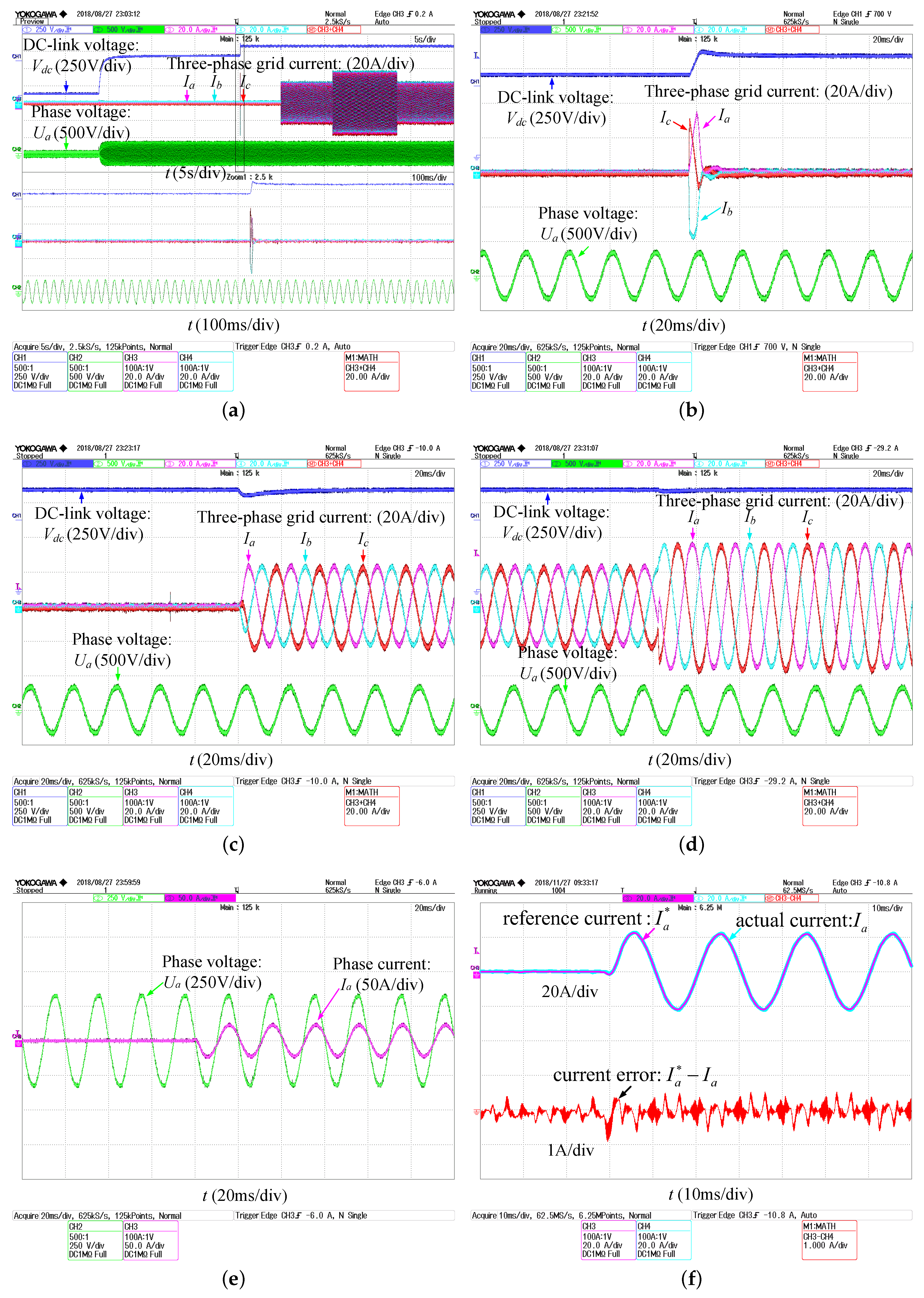
4.2. Experimental Results

To further support the theoretical analysis and simulation results, the experimental setup of GC-VSC was built in the laboratory, as shown in Figure 15. The parameters in experimental setup were the same as in simulation ones, which are listed in Table 1. Active power load consists of two parallel 100 Ω /10 kW resistors. The real-time algorithm was implemented in the hardware controller, based on TMS320C28346 DSP and EP3C16Q240 FPGA, whose output PWM signals are connected to converter by optical fiber. Experimental waveforms were captured by Yokogawa DL850 oscilloscope. Specifically, the hardware controller lacked of digital-to-analog converter and, since the reference current was a digital variable, it could not be directly measured by the oscilloscope. Therefore, real-time data were acquired by saving memory in Code Composer Studio (Ver.5.5.0) and the waveforms (Figure 16f and Figure 17b) were plotted in MATLAB.
Figure 16 and Figure 17 show the experimental results of the proposed and PCI-based control strategy, which correspond to the simulation results in Figure 13 and Figure 14, respectively. It can be observed that the experimental and simulation results match to a great extent. The slight difference is the distortion of grid current, which can be mainly attributed to harmonics contained in the grid voltage.
Figure 16 shows that the excellent stability and fast dynamic response of the proposed D-PCI-based control strategy can be obtained even though the GC-VSC experiences different load variation. The superiority can be further verified by the comparative experiments. From the results in Figure 16f and Figure 17b, the following can be concluded: (1) the current error of both strategies tends to zero, which means that tracking of ac reference signal with zero steady-state error can be realized from both methods; and (2) the proposed strategy has faster dynamic response, as the error current of the PCI-based strategy restores to zero after about 30 ms while there is almost no dynamic process for the proposed control strategy.

5. Conclusions

To attenuate the impact of axes cross-coupling caused by PCI controller, a novel D-PCI controller-based decoupling method in the stationary frame is proposed to track sinusoidal reference signals with zero steady-state error and achieve fast dynamic response. Moreover, an optimal gain method for parameter tuning is presented for enhancing the stability of the current loop. Comparing with PCI, the proposed D-PCI controller can obtain faster dynamic response, as well as better stability performance. Comparative simulations were performed and experimental results between the proposed and PCI controller were compared, which validated the superiority of the proposed D-PCI controller.

Author Contributions

Conceptualization, S.Z. and J.Z.; methodology, S.Z.; software, S.Z.; validation, S.Z., P.W. and B.Y.; data curation, K.L.; writing—original draft preparation, S.Z.; writing—review and editing, Z.Z.; project administration, J.Z. and K.L.; and funding acquisition, J.Z.

Funding

This research was funded by the National Natural Science Foundation of China grant number 51877042, the Project of China Postdoctoral Science Foundation grant number 2018M642138 and the Fundamental Research Funds for the Central Universities grant number 2242019R20010.

Conflicts of Interest

The authors declare no conflict of interest.

References

  1. Bose, B. Global Energy Scenario and Impact of Power Electronics in 21st Century. IEEE Trans. Ind. Electron. 2013, 60, 2638–2651. [Google Scholar] [CrossRef]
  2. Arbab-Zavar, B.; Palacios-Garcia, E.; Vasquez, J.; Guerrero, J. Smart Inverters for Microgrid Applications: A Review. Energies 2019, 12, 840. [Google Scholar] [CrossRef]
  3. Molina, M. Energy Storage and Power Electronics Technologies: A Strong Combination to Empower the Transformation to the Smart Grid. Proc. IEEE. 2017, 105, 2191–2219. [Google Scholar] [CrossRef]
  4. Bose, B. Power Electronics, Smart Grid, and Renewable Energy Systems. Proc. IEEE. 2017, 105, 2011–2018. [Google Scholar] [CrossRef]
  5. Pang, B.; Nian, H. Improved Operation Strategy with Alternative Control Targets for Voltage Source Converter under Harmonically Distorted Grid Considering Inter-Harmonics. Energies 2019, 12, 1236. [Google Scholar] [CrossRef]
  6. Xie, C.; Zhao, X.; Li, K.; Zou, J.; Guerrero, J.M. A New Tuning Method of Multi-Resonant Current Controllers for Grid-Connected Voltage Source Converters. IEEE J. Emerg. Sel. Top. Power Electron. 2019, 7, 458–466. [Google Scholar] [CrossRef]
  7. Busada, C.A.; Jorge, S.G.; Solsona, J.A. Resonant Current Controller With Enhanced Transient Response for Grid-Tied Inverters. IEEE Trans. Ind. Electron. 2018, 65, 2935–2944. [Google Scholar] [CrossRef]
  8. Nie, C.; Wang, Y.; Lei, W.; Li, T.; Yin, S. Modeling and Enhanced Error-Free Current Control Strategy for Inverter with Virtual Resistor Damping. Energies 2018, 11, 2499. [Google Scholar] [CrossRef]
  9. Holmes, D.G.; Lipo, T.A.; McGrath, B.P.; Kong, W.Y. Optimized Design of Stationary Frame Three Phase AC Current Regulators. IEEE Trans. Power Electron. 2009, 24, 2417–2426. [Google Scholar] [CrossRef]
  10. Guo, X.; Guerrero, J.M. General Unified Integral Controller With Zero Steady-State Error for Single-Phase Grid-Connected Inverters. IEEE Trans. Smart Grid. 2016, 7, 74–83. [Google Scholar] [CrossRef]
  11. Guo, X.Q.; Wu, W.Y. Improved current regulation of three-phase grid-connected voltage-source inverters for distributed generation systems. IET Renew. Power Gener. 2010, 4, 101–115. [Google Scholar] [CrossRef]
  12. Yuan, X.M.; Merk, W.; Stemmler, H.; Allmeling, J. Stationary-frame generalized integrators for current control of active power filters with zero steady-state error for current harmonics of concern under unbalanced and distorted operating conditions. IEEE Trans. Ind. Appl. 2002, 38, 523–532. [Google Scholar] [CrossRef]
  13. Harnefors, L.; Nee, H. Model-based current control of AC machines using the internal model control method. IEEE Trans. Ind. Appl. 1998, 34, 133–141. [Google Scholar] [CrossRef]
  14. Lascu, C.; Asiminoaei, L.; Boldea, I.; Blaabjerg, F. Frequency Response Analysis of Current Controllers for Selective Harmonic Compensation in Active Power Filters. IEEE Trans. Ind. Electron. 2009, 56, 337–347. [Google Scholar] [CrossRef]
  15. Lascu, C.; Asiminoaei, L.; Boldea, I.; Blaabjerg, F. High Performance Current Controller for Selective Harmonic Compensation in Active Power Filters. IEEE Trans. Power Electron. 2007, 22, 1826–1835. [Google Scholar] [CrossRef]
  16. Vidal, A.; Freijedo, F.D.; Yepes, A.G. Assessment and Optimization of the Transient Response of Proportional-Resonant Current Controllers for Distributed Power Generation Systems. IEEE Trans. Ind. Electron. 2013, 60, 1367–1383. [Google Scholar] [CrossRef]
  17. Briz, F.; Degner, M.W.; Lorenz, R.D. Analysis and design of current regulators using complex vectors. IEEE Trans. Ind. Appl. 2000, 36, 817–825. [Google Scholar] [CrossRef] [Green Version]
  18. Zmood, D.N.; Holmes, D.G. Stationary frame current regulation of PWM inverters with zero steady-state error. IEEE Trans. Power Electron. 2003, 18, 814–822. [Google Scholar] [CrossRef]
  19. Bae, B.; Sul, S. A compensation method for time delay of full-digital synchronous frame current regulator of PWM AC drives. IEEE Trans. Ind. Appl. 2003, 39, 802–810. [Google Scholar] [CrossRef]
  20. Pérez-Estévez, D.; Doval-Gandoy, J.; Yepes, A.G.; López, Ó. Positive- and Negative-Sequence Current Controller With Direct Discrete-Time Pole Placement for Grid-Tied Converters With LCL Filter. IEEE Trans. Power Electron. 2017, 32, 7207–7221. [Google Scholar] [CrossRef]
  21. Busada, C.A.; Jorge, S.G.; Leon, A.E.; Solsona, J.A. Current Controller Based on Reduced Order Generalized Integrators for Distributed Generation Systems. IEEE Trans. Ind. Electron. 2012, 59, 2898–2909. [Google Scholar] [CrossRef]
  22. Xie, C.; Zhao, X.; Li, K.; Liu, D.; Guerrero, J.M.; Vasquez, J.C. Phase Compensated Reduced Order Generalized Integrators for Grid-Tied VSCs With Harmonics Compensation Capability. IEEE Trans. Ind. Appl. 2018, 54, 2568–2578. [Google Scholar] [CrossRef]
  23. Hwang, J.G.; Lehn, P.W.; Winkelnkemper, M. A Generalized Class of Stationary Frame-Current Controllers for Grid-Connected AC–DC Converters. IEEE Trans. Power Del. 2010, 25, 2742–2751. [Google Scholar] [CrossRef]
  24. Jorge, S.G.; Busada, C.A.; Solsona, J.A. Frequency-Adaptive Current Controller for Three-Phase Grid-Connected Converters. IEEE Trans. Ind. Electron. 2013, 60, 4169–4177. [Google Scholar] [CrossRef]
  25. Jorge, S.G.; Busada, C.A.; Solsona, J. Reduced order generalised integrator-based current controller applied to shunt active power filters. IET Power Electron. 2013, 7, 1083–1091. [Google Scholar] [CrossRef]
  26. Yepes, A.G.; Vidal, A.; Malvar, J.; López, O.; Doval-Gandoy, J. Tuning Method Aimed at Optimized Settling Time and Overshoot for Synchronous Proportional-Integral Current Control in Electric Machines. IEEE Trans. Power Electron. 2014, 29, 3041–3054. [Google Scholar] [CrossRef]
Figure 1. The configuration of a distributed power generation system.
Energies 12 02426 g001
Figure 2. Implementation principle of ROGI and ROGI-based current controller.
Energies 12 02426 g002
Figure 3. The diagram of PCI-based current closed-loop for GC-VSCs.
Energies 12 02426 g003
Figure 4. α -axis and β -axis current response with PCI controller.
Energies 12 02426 g004
Figure 5. Structure of the proposed D-PCI current controller.
Energies 12 02426 g005
Figure 6. Bode plot of PCI and D-PCI controllers tuned at ω e = 2 · π · 50 rad/s.
Energies 12 02426 g006
Figure 7. α -axis and β -axes current response with D-PCI controller.
Energies 12 02426 g007
Figure 8. Bode plot of closed-loop current control based on D-PCI controller.
Energies 12 02426 g008
Figure 9. Bode plot of current closed-loop with delay compensation with D-PCI controller.
Energies 12 02426 g009
Figure 10. Root locus of current loop based on D-PCI controller: (a) general view; and (b) closer view of the dotted line frame.
Energies 12 02426 g010
Figure 11. Output current response with different gains of K when an abrupt change happens in the reference current.
Energies 12 02426 g011
Figure 12. The double closed-loop control scheme of GC-VSC.
Energies 12 02426 g012
Figure 13. Simulation results of the proposed control strategy: (a) general view of the DC-link capacitor voltage and three-phase grid current; (b) three-phase grid current when the GC-VSC operates in the state of PWM rectifier; (c) three-phase grid current when 10 kW active power is applied; (d) three-phase grid current when 10 kvar reactive power is added; (e) grid voltage and current of phase A when unity power control is implemented; and (f) reference current, actual current and current error of phase A when load changes.
Energies 12 02426 g013
Figure 14. Simulation results of the PCI-based control strategy: (a) three-phase grid current when 10 kW active power is applied; and (b) reference current, actual current and current error of phase A when load changes.
Energies 12 02426 g014
Figure 15. Experimental setup of the GC-VSC.
Energies 12 02426 g015
Figure 16. Experimental results of the proposed control strategy: (a) general view of the DC-link capacitor voltage and three-phase grid current; (b) three-phase grid current when the GC-VSC operates in the state of PWM rectifier; (c) three-phase grid current when 10 kW active power is applied; (d) three-phase grid current when 10 kvar reactive power is added; (e) grid voltage and current of phase A when unity power control is implemented; and (f) reference current, actual current and current error of phase A when load changes.
Energies 12 02426 g016
Figure 17. Experimental results of the PCI-based control strategy: (a) three-phase grid current when 10 kvar reactive power is applied; and (b) reference current, actual current and current error of phase A when load changes.
Energies 12 02426 g017
Table 1. Evaluation for different value of K.
Gain (K)Damping Ratio ξ OvershootResponse Speed
K < K o p t ξ > 1 noslow
K = K o p t ξ = 1 nofast
K > K o p t ξ < 1 havefast
Table 2. Simulation and experimental setup parameters.
SymbolParametersValueUnit
V s Phase-to-phase voltage380V
fGrid frequency50Hz
U d c DC-link voltage700V
LInductance of the L filter5mH
R L Equivalent resistance of the L filter0.05 Ω
C d c Capacitor of DC-link4000uF
R ( P ) Active power Load50(10) Ω (kW)
I q * (Q)Reactive power Load21.5(10)A(kvar)
f s w Switching frequency10kHz
f s Sampling frequency10kHz
B W Bandwidth of the current loop600Hz
k i p Proportional gain of the current loop12.3/
k i i Integral gain of the current loop123/
k v p Proportional gain of the voltage loop0.5/
k v i Integral gain of the voltage loop29.87/

