1. Introduction
So far there is no equipment, technology or method that can change the weather to prevent the occurrence of lighting. Buildings, devices, wiring and humans or animals can be damaged by lightning no matter whether it strikes directly or indirectly. In order to reduce the risk of loss, lightning protection measures have become an important issue [
1]. The voltage–current characteristics influence the current sharing and the residual voltages, in an effort to improve, the lightning performance of a distribution substation and careful selection of the electrical characteristics of the arresters to be connected is of great importance to achieve an adequate sharing of the lightning current and reduce the failure probability of the arresters [
2]. The installation position of surge arresters and the length of the underground cables influence significantly the lightning performance of high-voltage/medium-voltage (HV/MV) substations [
3].
According to the statistics by Taiwan Power Company in 2016, the average number of annual lightning strikes is 26,105. If the principles of lightning damage and the lightning risk factors can be known, some methods can be used to reduce the losses, for example, installing lightning receiving devices (the types of protector include lightning straps, lightning rods, and meshes), grounding grids, grounding devices, surge protective devices, metal shielding, fire protection measures, and warning signs. In order to ensure the safety of humans, devices, and buildings, the economic efficiency and the feasibility need to be considered in the protection measures.
The new trends in lightning protection standardization and an introduction to the use of a new software (RISK Multilingual 3) to simply apply the IEC 62305-2 standard on the risk assessment in lightning protection (Protection against lightning−Part 2: Risk management) in its next version is introduced (edition 2, 2010) [
4]. Failure risk of insulation and arresters at each region/node of the network, can be evaluated simultaneously, if the inputs are known using adaptive neural-fuzzy inference system (ANFIS). The inputs of ANFIS are the tower footing resistance, CFO and the rate of lightning occurrence [
5]. IEC 62305-2 “Protection against lightning” gives the risk assessment method and its evaluation. It requires a risk assessment to be carried out to determine the characteristics of any lightning protection system to be installed [
6].
There are studies that address related problems; Parametric studies using a procedure for the calculation of lightning flashover rates of transmission lines using a Monte Carlo method for lightning analysis of overhead transmission lines based on new Alternative Transients Program (ATP) capabilities has been performed to determine the sensitivity of the flashover rate with respect to some parameters of the transmission line and the return stroke [
7]. The Lightning Performance Assessment Tool (LPAT) simulation tool has been used by electric power utilities as a useful tool for the design and lightning protection of electric power systems, especially in cases where the transmission lines cross dissimilar geographic areas [
8], but there is no single one to solve the lighting protection problem.
Therefore, it is necessary to study lightning protection standards. The lightning protection standards include IEC, GB, IEEE, UL, NFPA, AS/NZS and so on. Moreover, the lightning information about Taiwan and abroad are shown in references [
9,
10,
11,
12,
13], respectively. This paper aggregates the zone data, line data, environment data, and protection measures of lightning based on the IEC62305 standard [
14]. In addition, a lightning risk calculation program with a Graphical User Interface is used to improve the efficiency in designing protection measurements. The paper is organized as follows:
Section 2 describes the application of lightning risk and surge protective devices and the flow diagram of the lightning risk design process. Use of a calculation program simulation and analysis of lightning risks is provided in
Section 3. SPD application and conclusions follow in
Section 4 and
Section 5, respectively.
2. Application of Lightning Risk and Surge Protective Device
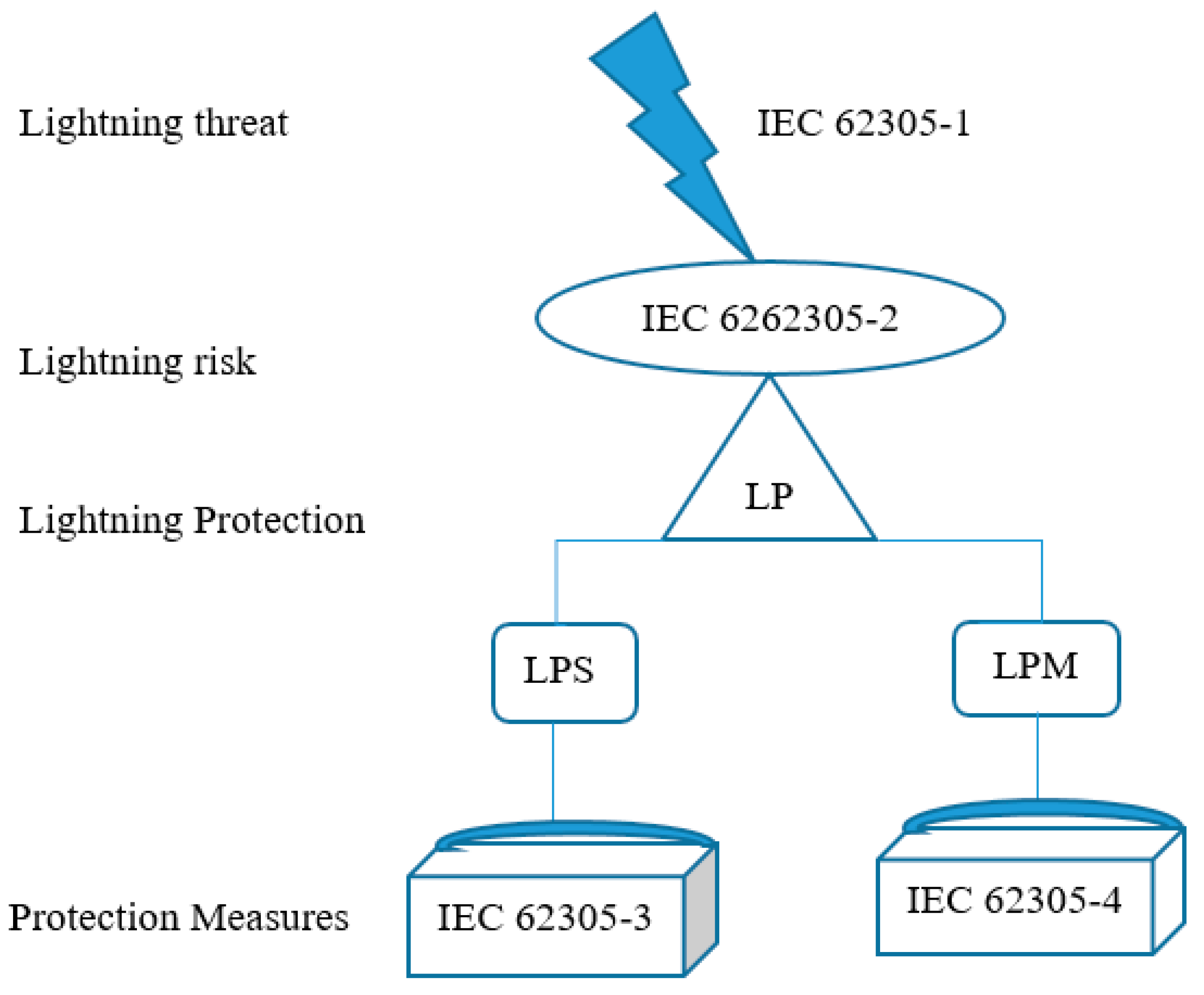
The study presents the lightning information from IEC62305-2 (Risk management), IEC62305-3 (Physical damage to structures and life hazard), and IEC62305-4 (Electrical and electronic systems within structures) and proposes suitable protection measures, which include a lightning protection system (LPS), and lightning protection measures (LPMs), to divide lightning protection zones and to calculate gaps.
Figure 1 shows the introduction of IEC62305.
Types of loss
L1: Loss of human life
L2: Loss of service to the public
L3: Loss of cultural heritage
L4: Loss of economic value
Risk types
The calculation of lightning risk about R1~R4 and Rx: Analyze the lightning location for each risk.
(LPS) The protection measures about reducing the physical damage and human life, for example, installing lightning receiving devices, grounding grids, and grounding devices.
The protection measures for reducing the lightning damage for electrical and electronic systems, for example, using metal shielding and installing SPD.
2.1. Lightning Risk
Lightning risk means the ratio of annual losses to the value of the protection. The formula is the multiplication of the number of annual lighting risks, the probability of structure damage, and the rate of lightning stroke loss. IEC62305-2 defines four types of risk and risk tolerances. The failure risk of a network component due to lightning stroke presents the probability that the lightning surge exceeds the withstood voltage [
15]. Different lightning locations may cause different values of the risk, which includes touch voltage, step voltage, physical damage, and internal faults, as shown in
Table 1. The types of lightning risk are as follows:
Risk of loss of human life in a structure (R1)
Risk of loss of service to the public in a structure (R2)
Risk of loss of cultural heritage in a structure (R3)
Risk of loss of economic value in a structure (R4)
The corresponding loss rates for various types of risks are as follows:
Loss of human life (L1)
Loss of service to the public (L2)
Loss of cultural heritage (L3)
Loss of economic value (L4)
The definitions of each lightning risk are as follows:
The lightning risk value of lightning striking the structure (S1):
RA: Shock to living beings due to touch and step voltages (the distance from inside and outside of the structure is 3 m).
RB: Fire and explosion effects inside the structure due to mechanical and thermal effects including dangerous sparking.
RC: Failure of electrical and electronic systems due to LEMP on internal installations and incoming services.
The lightning risk value of lightning striking the ground near the structure (S2):
The lightning risk value of lightning striking services connected to the structure (S3):
RU: Injuries of living beings caused by touch voltage inside the structure due to lightning current injected into a line entering the structure.
RV: Fire effects inside the structure due to mechanical and thermal effects including dangerous sparking between incoming lines and metal installations.
RW: Failure of internal systems caused by overvoltage induced on incoming lines and transmitted to the structure.
The lightning risk value of lightning striking the ground near services connected to the structure (S4):
2.2. The Principle of Risk Management
The risk management is the formula as follows:
where
RX: Lightning risk,
NX: Number of annual lighting risk,
PX: Probability of structure damage,
LX: Rate of lightning stroke loss
The rate of lightning stroke loss for the risk of human life and the risk of economic loss are different because the risk of human life considers time and number of people; the risk of economic loss considers animal considers the economic value, for example, animals, structures, and internal system. The comparison is shown in
Table 2.
The data of lightning structure is complicated, which contains environment data, line data, zone data, and economic data.
2.3. Protective Measurements and Cost Saving
The tolerance is needed to be considered after calculating the risk, which is used to select the correct protective measures and saves cost. The introduction of protective measures and annual cost savings are as follows:
2.3.1. Protective Measures
If the risk value is higher than the tolerance, it may use the protective measures to reduce. The components of the risk value and the protective measures in IEC62305-2 are as shown in
Table 3.
2.3.2. Annual Cost Savings
The calculation process of the annual cost saving is as follows:
- (a)
The annual cost before using protective measures (
$)
- (b)
The annual cost after using protective measures (
$)
- (c)
The annual cost of protective measures (
$)
- (d)
The annual cost saving (
$)
where
ct is the total cost,
CP is the cost of protective measures,
i is the percentage of the interest rate,
a is the percentage of the depreciation rate,
m is the percentage of the maintenance rate.
2.4. Design Process of the Lightning Risk
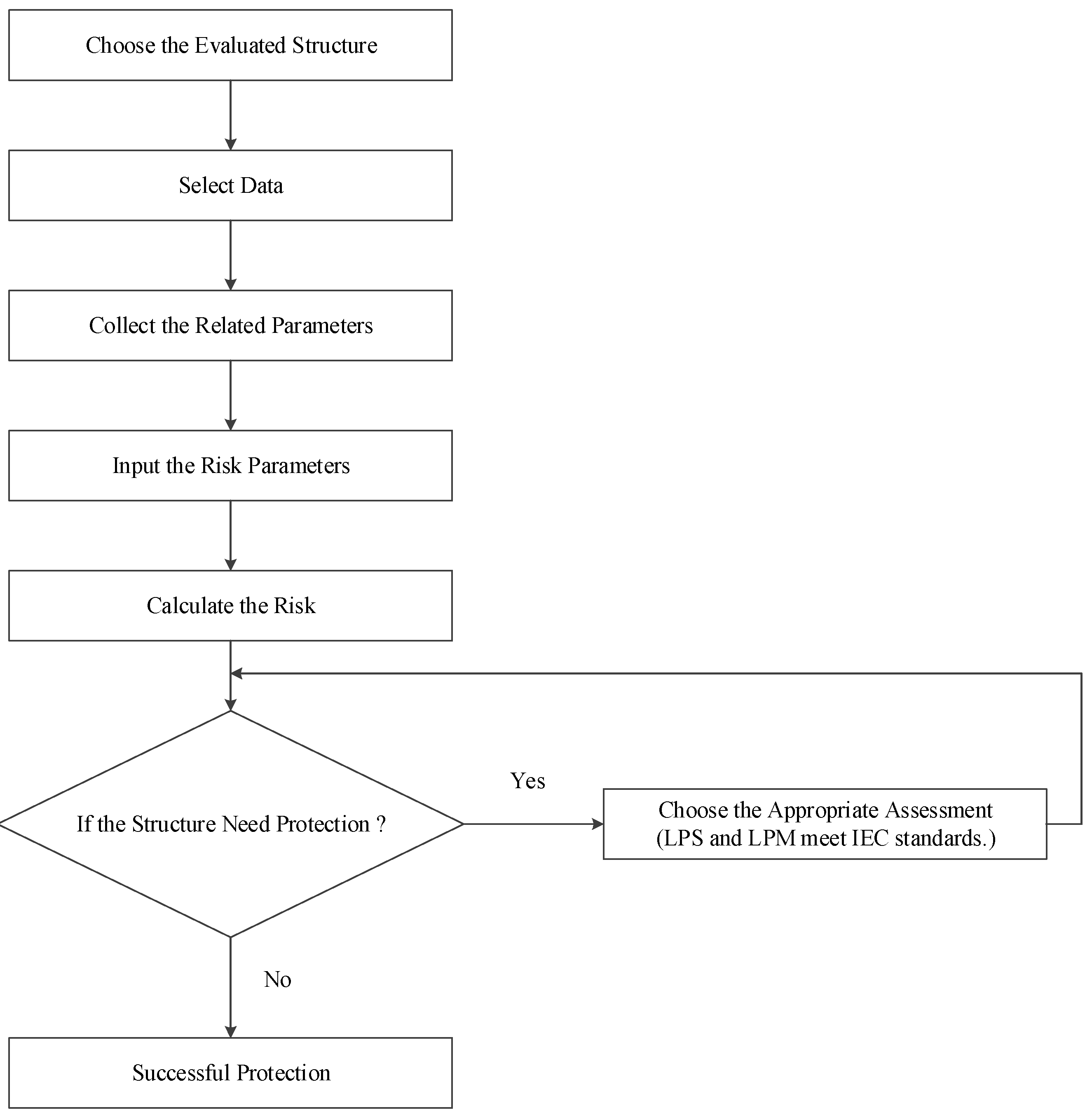
The flow diagram of design process of the lightning risk is shown in
Figure 2 and the introduction is as follows:
- (1)
Structure selection
- (2)
Data collection
- (a)
Structure diagram
- (b)
Standard about the project
- (3)
Parameter aggregation
- (a)
The environment data
- (b)
The structure data
- (c)
The line data
- (d)
The zone data
- (e)
The economic data
- (4)
Input parameter of the risk
- (5)
The computation of risk
- (a)
Risk of human life
- (b)
Risk of economic value
- (c)
Tolerance check
- (6)
Protective measures selection
- (a)
Correct protective measures selection
- (b)
LPS and LPM conform to IEC Standard
- (c)
The structure is already protected
3. Simulation and Analysis for Lightning Risk
This paper evaluates the lightning risk based on the IEC62305 standard and uses Visual Basic (VB) to design a suitable graphical interface. For this simulation case, the length, width, and height of the building are 100 m, 50 m, and 15 m, respectively. There is another building, power line, and communication line around the building, as shown in
Figure 3. This section will use the structure as an example to simulate the risk to human life and the risk to economic value. The setting values of the parameters refer to the data of IEC62305.
3.1. Risk Parameters Setting
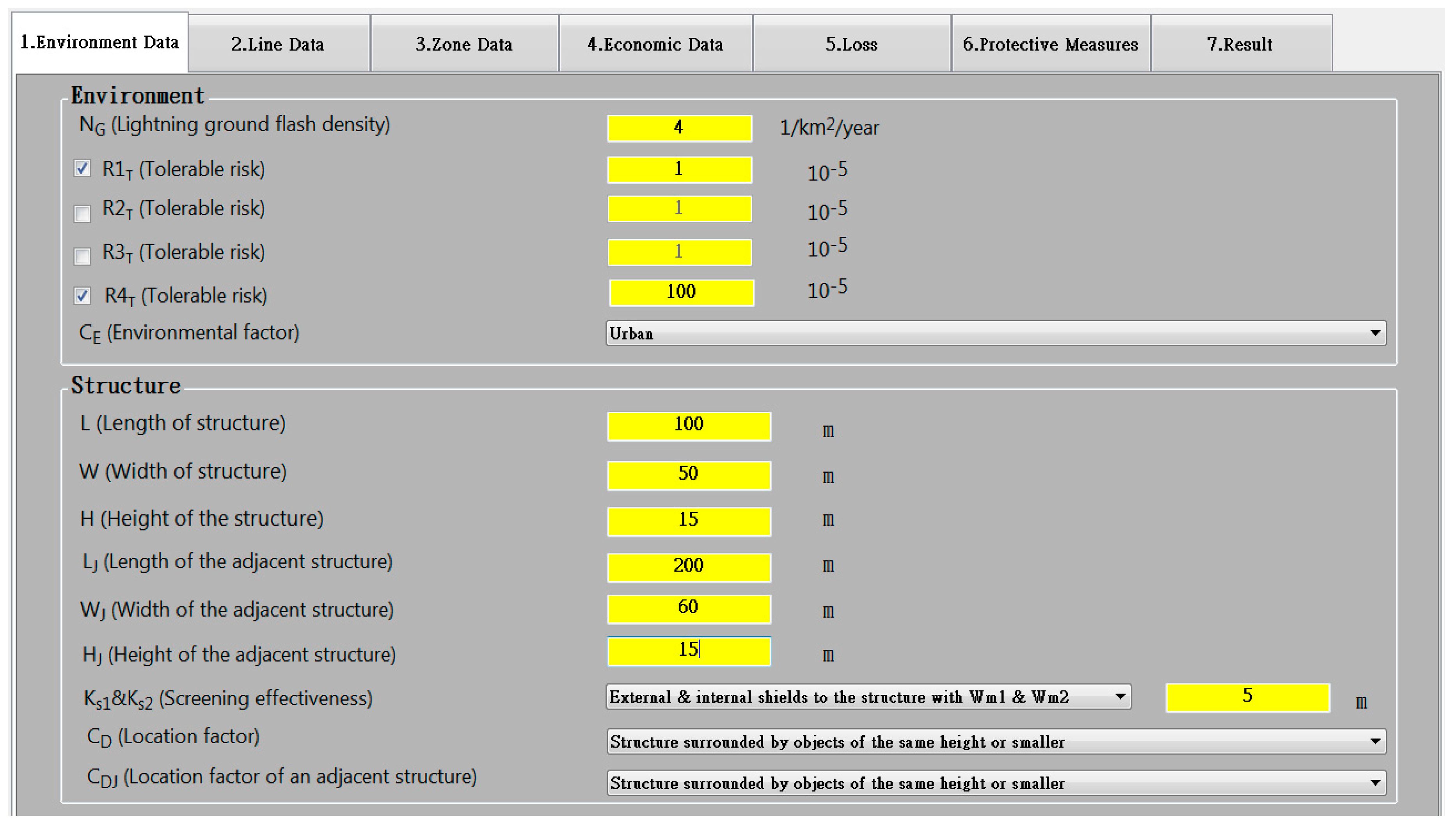
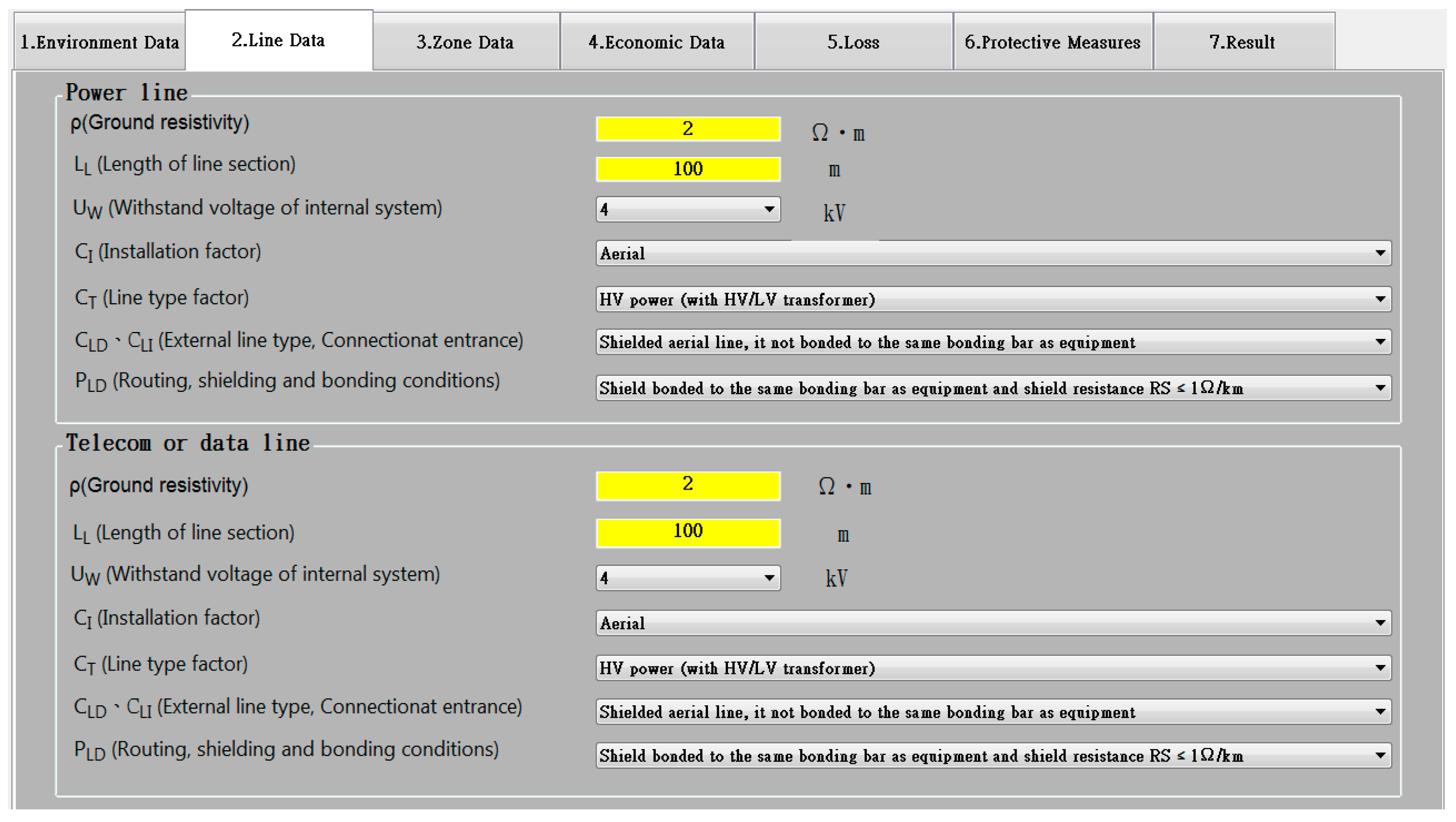
Because the risk parameters are quite complicated, this paper uses
Figure 4 and
Figure 5 to show the setting values of the risk parameters in the simulation.
3.2. Result and Analysis
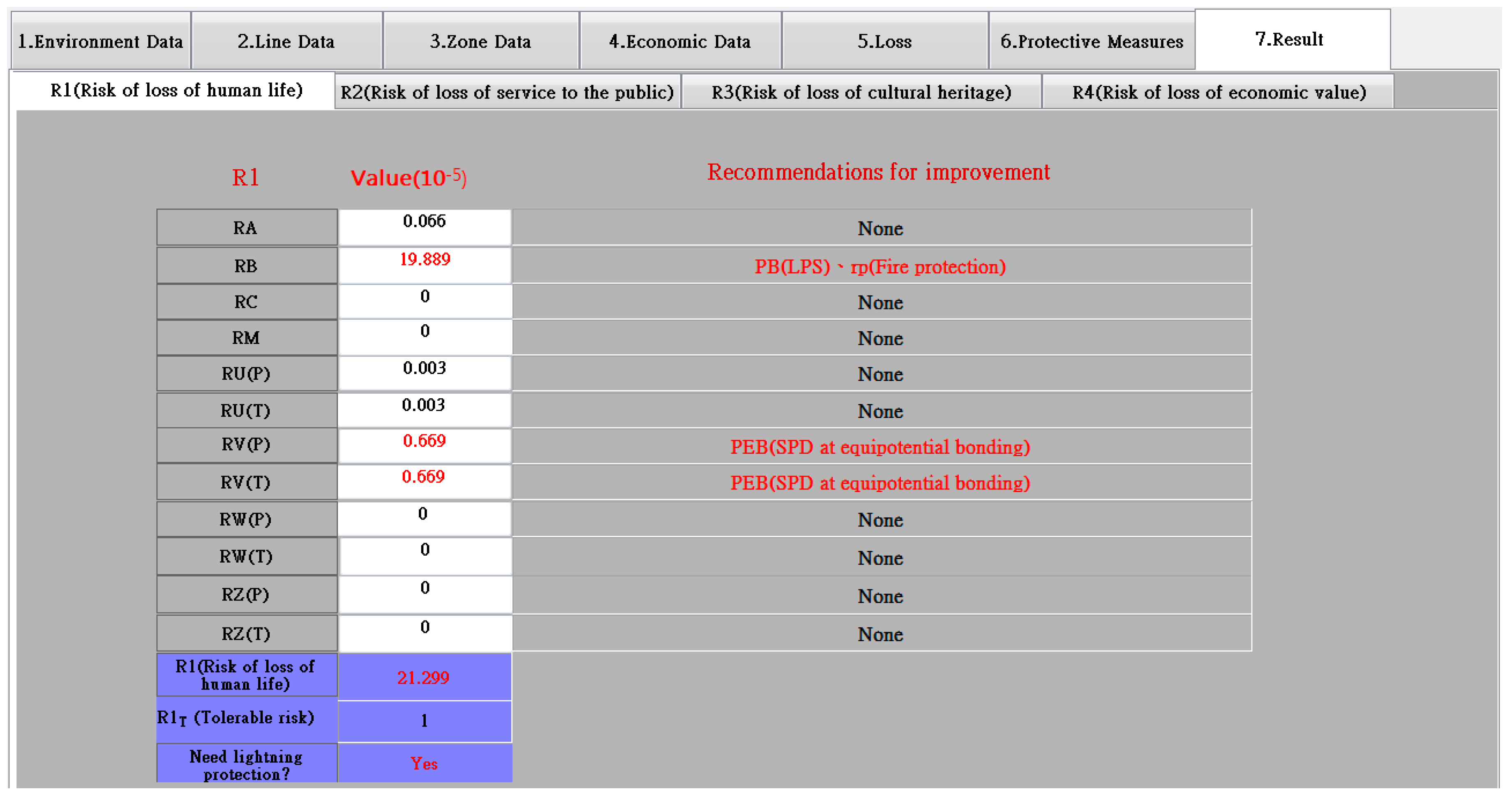
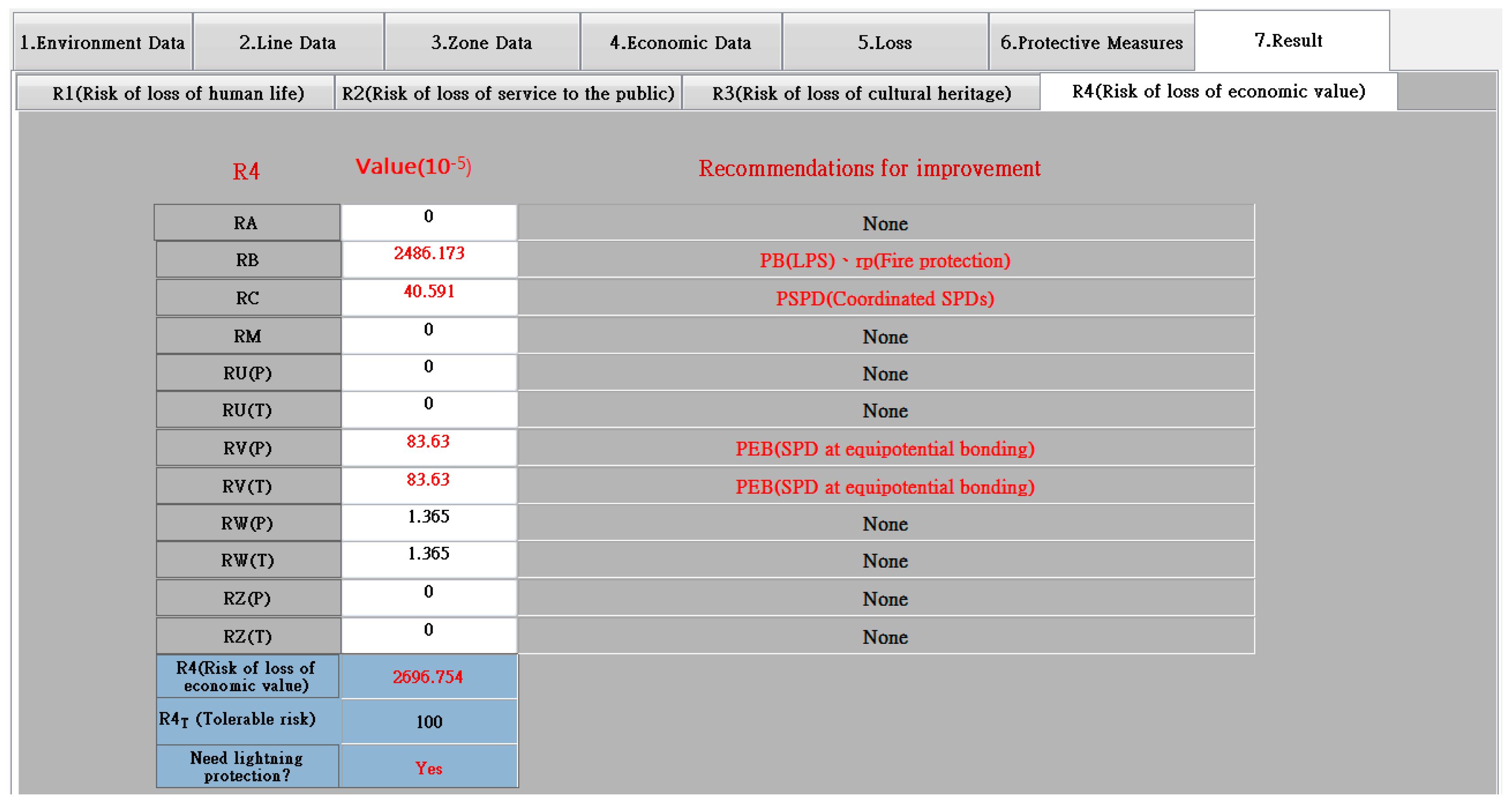
After inputting the risk parametera, the result of the simulation for risk to human life and risk to economic value are shown in
Figure 6 and
Figure 7, respectively. In addition, the researchers verified the calculation program’s accuracy with manual calculations, which gave the same results. Calculating the lightning risk using the IEC62305 sta
ndard is burdensome and takes time, and therefore to solve/simplify this for quick calculations we design this study as shown in
Figure 4,
Figure 5,
Figure 6,
Figure 7,
Figure 8,
Figure 9 and
Figure 10. The lightning risk calculation program with graphical user interface based on IEC62305 standard is discussed. A graphical user interface or calculation program can make work easy and save time because calculation lightning risk numerically or manually is complicated and takes time. It becomes easy and saves time when done with a calculation program.
Parameter
P means power line and
T means communication line in the result of the simulation. Because the value of R1 is caused by
RB and
RV, and the value of R4 is caused by
RB,
RC, and
RV, both are higher than the tolerance. Therefore, LPS and SPD are needed to install so as to reduce the value of the risk, as shown in
Table 3. The protection measurements are as follows:
- (1)
Corresponding with the lightning protection system of LPL I (PB = 0.02).
- (2)
Corresponding with the lightning protection system of LPL III-IV (PEB = 0.03).
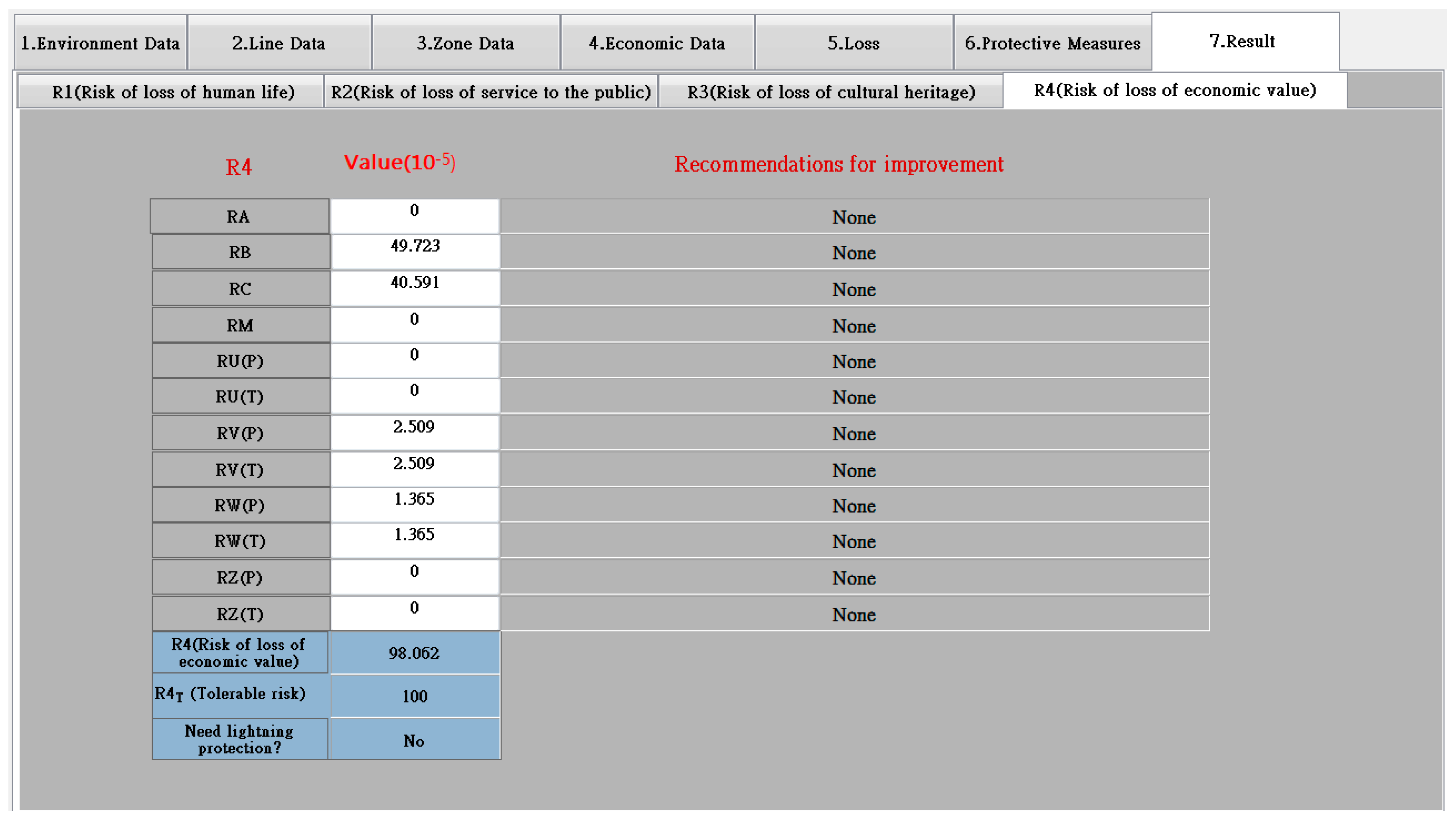
After using the protection measures, the value of risk to human life reduces from 21.299 × 10
−5 to 0.439 × 10
−5 and the value of risk of economic value reduces from 2696.754 × 10
−5 to 98.062 × 10
−5, as shown in
Figure 8 and
Figure 9. The results mean that the protection measures place the values of the risk below the tolerance.
This paper considers the annual cost savings. Assuming the cost of protection measures, the interest rate, the depreciation rate, and the maintenance rate are 150,000 $, 4%, 5%, and 1%, respectively, by using Equations (2)–(5), the annual cost before using protective measures, the annual cost after using protective measures, the annual cost of protective measures, and the annual cost saving are $925,000, $33,635, $15,000 and $876,365, respectively.
3.3. Summary
For the lightning risk, the selection of LPS, fire protection measures, and SPD are important. Because the protection measures are related to the cost, the main points for the calculation of the risk is as follows:
- (1)
Main point for installation the lightning protection system (LPS)
LPS is associated with
RA and
RB, the functions are formulated as follows:
The functions show that the impact factor for RA is PTA (structure protection measure). If the frames of the structure are used to be the grounding grids, the value of PTA is zero and the value of RA is also zero. In addition, the impact factor RB is rf (the fire risk). If the structure is without fire load, the value of rf and RB is zero. Another case is when the fire load is below than 400 MJ/m2, the value of RB will change to 0.001 so as to reduce the value of RB. When the value of RA and RB are low, it means that the demand of LPS measure is not required.
- (2)
Main point for installation the fire protection system
The fire protection measure is associated with
RB and
RV. The function of
RV is formulated as follows:
For the value of
RV, the main point is
CLD (the type of external wire line and the factor of entrance connection) and
rf. If using lightning protected cable, equivalent potential connection or structure without fire load, one of C
LD and
rf decrease to zero and
RV is also zero. When the value of
RB and
RV are low, it means that the fire protection measure demand is not required.
- (3)
Main point for installation SPD
The parameters associate SPD are RC, RM, RU, RV, RW, and RZ. The main point of RV is discussed in Equation (2) and the other functions of risk are formulated as follows:
For the value of RC, RU, and RW, the main point is CLD. If using lightning protected cable and equivalent potential connection, RC, RU, and RW can reduce to zero. For RM, the main point is PMS, which contains KS1 (the width of the external shielding), KS2 (the width of the internal shielding), and KS3 (the arrangement of internal wire). If the width of the shielding is decreased or the arrangement of wire uses shielding cable or let the wire in the metal tube, the value of RM will reduce. For RZ, the main point is CLI (the type of internal wireline and the factor of entrance connection). If using shielded cable and has equivalent potential connection with the device, the value of RZ can reduce to zero.
- (4)
The Main point for lightning risk
Table 4 shows the condition that the value of risk parameter is zero. The demand of protection measure may decrease as the risk decreases.
4. SPD Application
If a wireline connects SPD and device is too long, the voltage across the device may increase twice as originally due to overvoltage, electromagnetic oscillation, and effect of loop inductance so as to the device will damage. However, in response to the demand for increased the number of device installation, Taiwan Power Company hope to develop the smart grid and replace traditional E/M relay by an intelligent electronic device (IED). This section uses EMTP to simulate and discuss the effect of loads and the connection distance on effective protection distance of SPD.
4.1. Simulation Model
The simulation model is the low-voltage single-phase power system in this paper. The source, which is regarded as lightning surge current and SPD are in parallel. The surge current flows to load through the wireline, as shown in
Figure 10. The model 1 is used to simulate case 1 to 3. Model 2, which adds the full-wave rectifier circuit, DC load, and capacitor 6μH, used to simulate case 4, as shown in
Figure 11.
The information of combination waveform to simulate lightning surge is that the open-circuit voltage is 1.2/50 μs and the short-circuit current is 8/20 μs. According to ANSI/IEEE Std. C62.41-2002 [
16] and ANSI/IEEE Std. C62.42-2002 [
17], the zone in the house can be divided into: (1) zone A contains all of the sockets and the distance from zone B is more than 10 m and from zone C is more than 20 m; (2) zone B contains feeders and the secondary switchboard; (3) zone C contains the main switchboard and the entrance wire. Zone A and B may be damaged by 6 kV voltage and zone C may be damaged by the voltage above 10 kV. Because this paper discusses an application for a house interior, the 6 kV/3 kA combination waveform is selected, as shown in
Figure 12 and
Figure 13.
The wireline is a solid conductor and has no insulation tube. The diameter of metal-core is 1.6 mm and the thickness of metal layer 0.6 mm and the value of resistivity is 1.724 × 10⁻⁸ Ω/m. The value of equivalent resistance, inductance and capacitance are 0.008574 Ω/m, 0.3145 μH/m, and 42.069 pF/m, respectively.
IEC60664-1 defines four types to correspond to the rated voltage (U
W) of the device, as shown in
Table 5: (1) class I is the location for the electronic equipment; (2) class II is the location for the residential appliances; (3) class III is the location for the distribution wires; (4) class IV is the location for the entrance wires. Above all, U
W is 1.5 kV and U
P of SPD is 1.2 kV in this simulation case.
4.2. Test Cases
The load type in case 1 to three is a resistive load, capacitive load, and inductive load, respectively. The resistive load values include 10 Ω, 100 Ω, and 1000 Ω and the open circuit. The value of inductive load contains 1 μH, 10 μH, and 100 μH. The value of inductive load includes 1 μH, 10 μH, and 100 μH. Using different distances between the load and SPD (1 m, 10 m, and 100 m) we examine whether the voltage exceeds the tolerated voltage. The results, in
Table 6, show that the voltage will exceed the tolerated voltage. The load type in case 4 includes 10 Ω, 100 Ω, and 1000 Ω and the open circuit. In addition, the discussion is same as the mentioned above. The results are shown in
Table 7 and the values are all the maximum voltages of the load.
4.3. Results Comparison
The results in case 1 are as follows: for the resistive load, the length of the wire is too short so that the value of resistance is small and the changes in the load hardly effect the tolerated voltage of the device, which means the voltage of the device and SPD are same. For the capacitive load, the oscillation is found although the length of wire is only 1 m. As the value of capacitor increases, the amplitude of the oscillation increases but the frequency of the oscillation decreases. For the inductive load, the voltage of the device is equal to half of the residual voltage of SPD, when the value of inductance is small. The voltage of the device approaches the residual voltage of SPD (1200 V) only if the value of inductance increases.
The results in case 2 are as follows: for the resistive load, the oscillation is found when the value of resistance increases. The voltage of the device is 1453 V when the load is greater than 1000 Ω. If the voltage exceeds the tolerated voltage, the device will be broken. For the capacitive load, all the values of voltage are greater than the voltage limit. As the value of capacitor increases, the amplitude of the oscillation increases but the frequency of the oscillation decreases. For the inductive load, the oscillation is found when the value of inductance increases. The voltage of the device is 1609.92 V when the load is 100 μH. If the voltage exceeds the rated voltage, the device will be broken.
The results in case 3 are as follows: for the resistive load, as the value of resistance increases, the amplitude of the oscillation increases but the frequency of the oscillation decreases. The voltage of the device is 1907.99 V when the load is 1000 Ω. For the capacitive load, the value of capacitance increases as the voltage of device decreases. For the capacitive load, as the value of inductance increases, the amplitude of the oscillation increases but the frequency of the oscillation decreases. The voltage of the device is 2308.85 V when the load is 100 μH. If the voltage exceeds the tolerated voltage, the device will be broken.
After the comparison of each case, increasing the length of the wire may cause the results to change as follows: for the resistive load, the voltage of the device and the amplitude of the oscillation will increase but the frequency of the oscillation will decrease. For the capacitive load, when the voltage increases, the amplitude of the oscillation will decrease, but the voltage increases only if the inductance is 100 μH.
The results in case 4 are as follows: when the value of the resistance increases, the voltage of the device only increases slightly. For 1 m length of the wire, the resistance of the load is 10 Ω can destroy the device. For 100 m length of the wire, the device can be protected by SPD. In addition, when the load is constant, when the length of wire increases, the voltage of the device will increase at first and then decrease.
5. Conclusions
The user interface in this paper offers a calculation of lightning risk and it based on the IEC62305 standard. To achieve the most economical protection design for a structure, additional protection measures and annual savings are considered. In order to improve the benefits of SPD installation, the low-voltage single-phase power system is simulated in this paper and the test cases are used to discuss the effective protection distance of SPD. The results indicate that the changes in the type of loads and the connection distance will affect the effectiveness of SPD. Therefore, the correct SPD installation and the selection of the distance can protect the device and lower the cost.
The results show that after using the protective measures, the value of the risk to human life reduces from 21.299 × 10⁻⁵ to 0.439 × 10⁻⁵ and the value of the economic value risk reduces from 2696.754 × 10−5 to 98.062 × 10⁻⁵ meaning that the protection measures set the values of the risk below the tolerance. Considering the annual cost savings, we assume the cost of protection measures, the interest rate, the depreciation rate, and the maintenance rate are $150,000, 4%, 5%, and 1%, respectively. The annual cost before using protective measures, the annual cost after using protective measures, the annual cost of protective measures, and the annual cost savings are $925,000, $33,635, $15,000, and $876,365, respectively. Consequently, it is feasible that the simulation result can provide users with good suggestions to choose the best installation location and achieve the most effective protection design.
Manually/analytically, calculating the lightning risk using IEC62305 standard is burdensome and takes time, so to address this problem we use Visual Basic (VB) to design a suitable Graphical user interface and a calculation program has been designed and it can make the task easy and save time.
Author Contributions
C.-H.L. and Y.B.M.; Software, Writing—original draft and review & editing, Investigation, Software validation, Data curation and Validation; Y.-T.C., Conceptualization, Software edition, Writing—graphical editing; C.-C.K.; Methodology, Writing—review & editing, Leading and commenting the team; H.-Y.C.; Software validation, Methodology, Data curation
Funding
This research received no external funding.
Conflicts of Interest
The authors declare no conflicts of interest.
References
- Mounir, M.M.; Mahmoud, A.E. Development of Lightning Risk Assessment Software in Accordance with IEC 62305-2. In Proceedings of the 2013 International Conference on Computing, Electrical and Electronic Engineering (ICCEEE), Khartoum, Sudan, 26–28 August 2013. [Google Scholar]
- Christodoulou, C.A.; Vita, V.; Maris, T.I. Lightning protection of distribution substations by using metal oxide gapless surge arresters connected in parallel. Int. J. Power Energy Res. 2017, 1, 1–7. [Google Scholar] [CrossRef]
- Trainba, M.; Christodoulou, C.A.; Vita, V.; Ekonomou, L. Lightning overvoltage and protection of power substations. WSEAS Trans. Power Syst. 2017, 12, 107–114. [Google Scholar]
- Bouquegneau, C.; Lecomte, P. New Lightning Protection Standardization Trends for the Lightning Risk Assessment; Use of the Risk Multilingual 3 Software. In Proceedings of the 2010 Asia-Pacific International Symposium on Electromagnetic Compatibility, Beijing, China, 12–16 April 2010. [Google Scholar]
- Shariatinasab, R.; Safar, J.G.; Mobarakeh, M.A. Development of an adaptive neural-fuzzy inference system based meta-model for estimating lightning related failures in polluted environments. IET Sci. Meas. Technol. 2014, 8, 187–195. [Google Scholar] [CrossRef]
- Shariatinasab, R.; Vahidi, B.; Hosseinian, S.H. Statistical evaluation of lightning-related failures for the optimal location of surge arresters on the power networks. IET Gen. Transm. Distrib. 2009, 3, 129–144. [Google Scholar] [CrossRef]
- Martinez, J.A.; Castro-Aranda, F. Lightning performance analysis of overhead transmission lines using the EMTP. IEEE Trans. Power Deliv. 2005, 20, 294–300. [Google Scholar] [CrossRef]
- Karampelas, P.; Ekonomou, L.; Panetsos, S.; Chatzarakis, G.E. LPAT: An interactive simulation tool for assessing the lightning performance of Hellenic high voltage transmission lines. Appl. Soft Comput. 2011, 11, 1380–1387. [Google Scholar] [CrossRef]
- Orille-Fernández, Á.L.; Khalil, N.; Rodríguez, S.B. Failure Risk Prediction Using Artificial Neural Networks for Lightning Surge Protection of Underground MV Cables. IEEE Trans. Power Deliv. 2006, 21, 1278–1282. [Google Scholar] [CrossRef]
- IEC. Low-Voltage Surge Protective Devices: Surge Protective Devices Connected to Low-Voltage Power Distribution Systems—Selection and Application Principles; IEC 61643-12; IEC: Geneva, Switzerland, 2008. [Google Scholar]
- IEC. Insulation Coordination for Equipment within Low-Voltage Systems—Principles, Requirements and Tests; IEC 60664-1; IEC: Geneva, Switzerland, 2002. [Google Scholar]
- IEC. Testing and Measurement Techniques—Surge Immunity Test; IEC61000-4-5; IEC: Geneva, Switzerland, 2010. [Google Scholar]
- IEC. Protection against Lightning—Part 1–4; IEC 62305; IEC: Geneva, Switzerland, 1995. [Google Scholar]
- Stefanescu, S.; Botezan, A. Overview of the Protection Lightning Standards Suite EN/IEC 62305. In Proceedings of the 2016 International Conference and Exposition on Electrical and Power Engineering (EPE), Iasi, Romania, 20–22 October 2016. [Google Scholar]
- IEEE Guide on the Surge Environment in Low-Voltage (1000 V and Less) AC Power Circuits; ANSI/IEEE Std. C62.41.1-2002; IEEE Standard Association: Piscataway, NJ, USA, 2002.
- IEEE Recommended Practice on Characterization of Surges in Low-Voltage (1000 V and Less) AC Power Circuits; ANSI/IEEE Std. C62.41.2-2002; IEEE Standard Association: Piscataway, NJ, USA, 2002.
- IEEE Guide for the Application of Surge-Protective Components in Surge Protective Devices and Equipment Ports—Part 2 Metal-Oxide Varistors (MOVs); ANSI/IEEE Std. C62.42.2-2002; IEEE Standard Association: New York, NY, USA, 2016.
© 2018 by the authors. Licensee MDPI, Basel, Switzerland. This article is an open access article distributed under the terms and conditions of the Creative Commons Attribution (CC BY) license (http://creativecommons.org/licenses/by/4.0/).
