1. Challenges and Requirements Concerning Electric Drives in Aviation
Studies of the future trends in aviation concluded that in the next few years, more-electric aircraft using hybrid propulsion systems and all-electric aircraft incorporating pure electric propulsion will be technically feasible, offering benefits for the environment in terms of pollution, noise, and for business [
1,
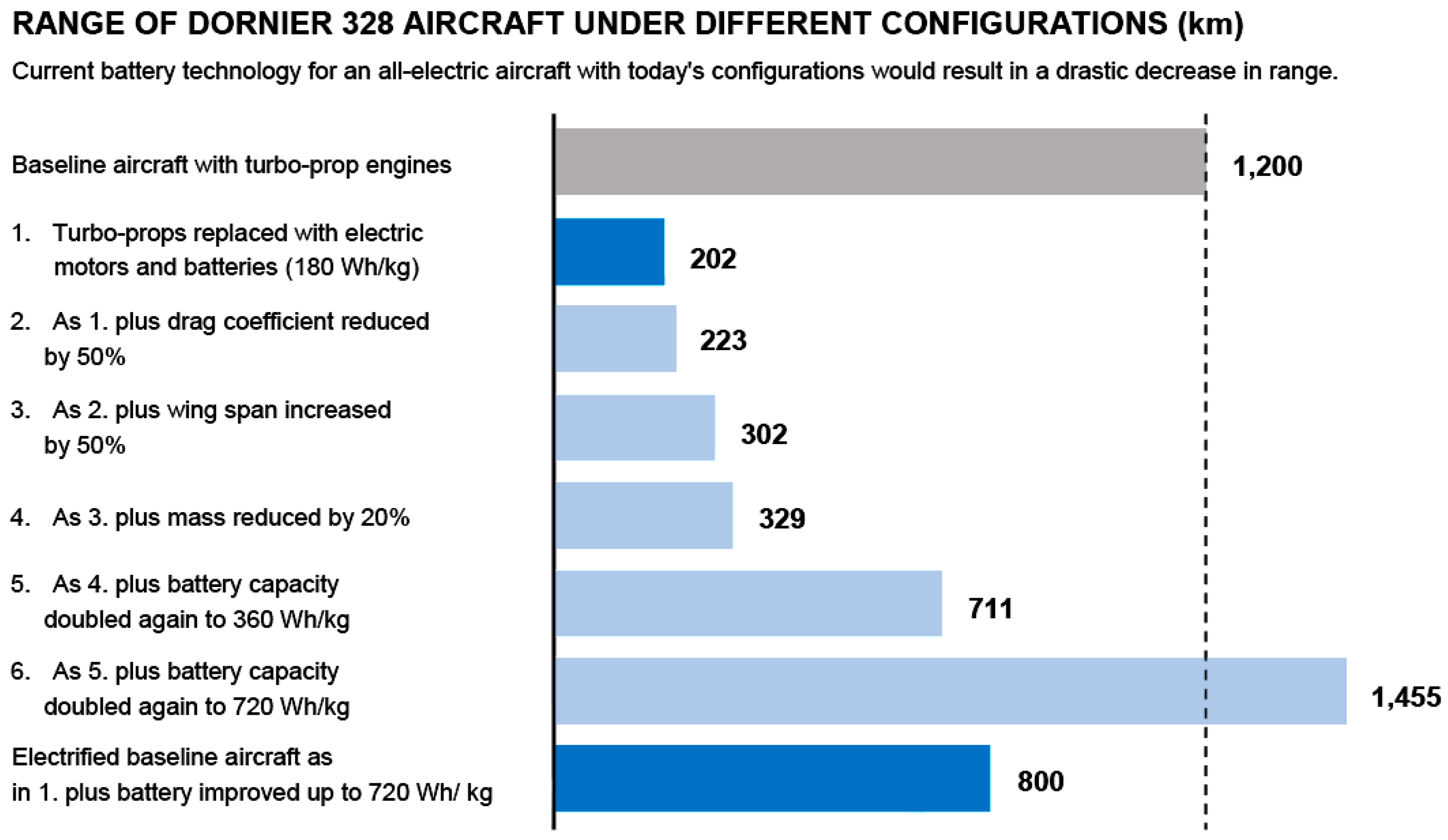
2]. The potential of future technologies covered in this study are displayed in
Figure 1. The advances in technology that have had several impacts on the flight-range of electric aircraft are presented using a Dornier 328 aircraft as an example. At the top of the graph, a conventionally powered aircraft is shown. The bars below indicate several flight ranges when incorporating electric drive components, improving aircraft design, and using batteries with different energy to weight ratios.
With the implementation of different future technologies, the flight range of an electric aircraft could reach or outperform a conventional aircraft burning fossil fuel. In this study, the increase in gravimetric battery density roadmap shows that the required level for aviation of 500 Wh/kg will be reached by 2025. At present, densities of 250 to 320 Wh/kg have been produced, which is close to the requirement. The motivation in researching this subject area is based on significantly reducing energy usage, noise, and emissions [
2,
3]. Electrifying the propulsion of aircraft is possible with hybrid systems or electric propulsion. Future all-electric aircraft will have highly dynamic electric drives which instantly develop torque over a wide range of speeds. The instantaneous development of torque can increase security, such as when performing a go-around procedure. Electric drives have another benefit: they work independent of the surrounding air pressure. Additionally, electric systems are increasingly incorporated into on-board systems.
Studies concerning the possibilities of applications to aircraft to replace hydraulics have already been completed by several companies, such as the United Technologies Research Center. Lightweight energy storage systems are crucial for energy efficient operation and flight distance. Lightweight energy storage systems are also important for electric drives, which lower the take-off mass. Thus, a future task is to further optimize electric drives and gas turbine generators in terms of the power to weight ratio. Changing the machine design from conventional principles to more advanced technologies will likely also be required, such as superconducting machines with high-temperature superconductors.
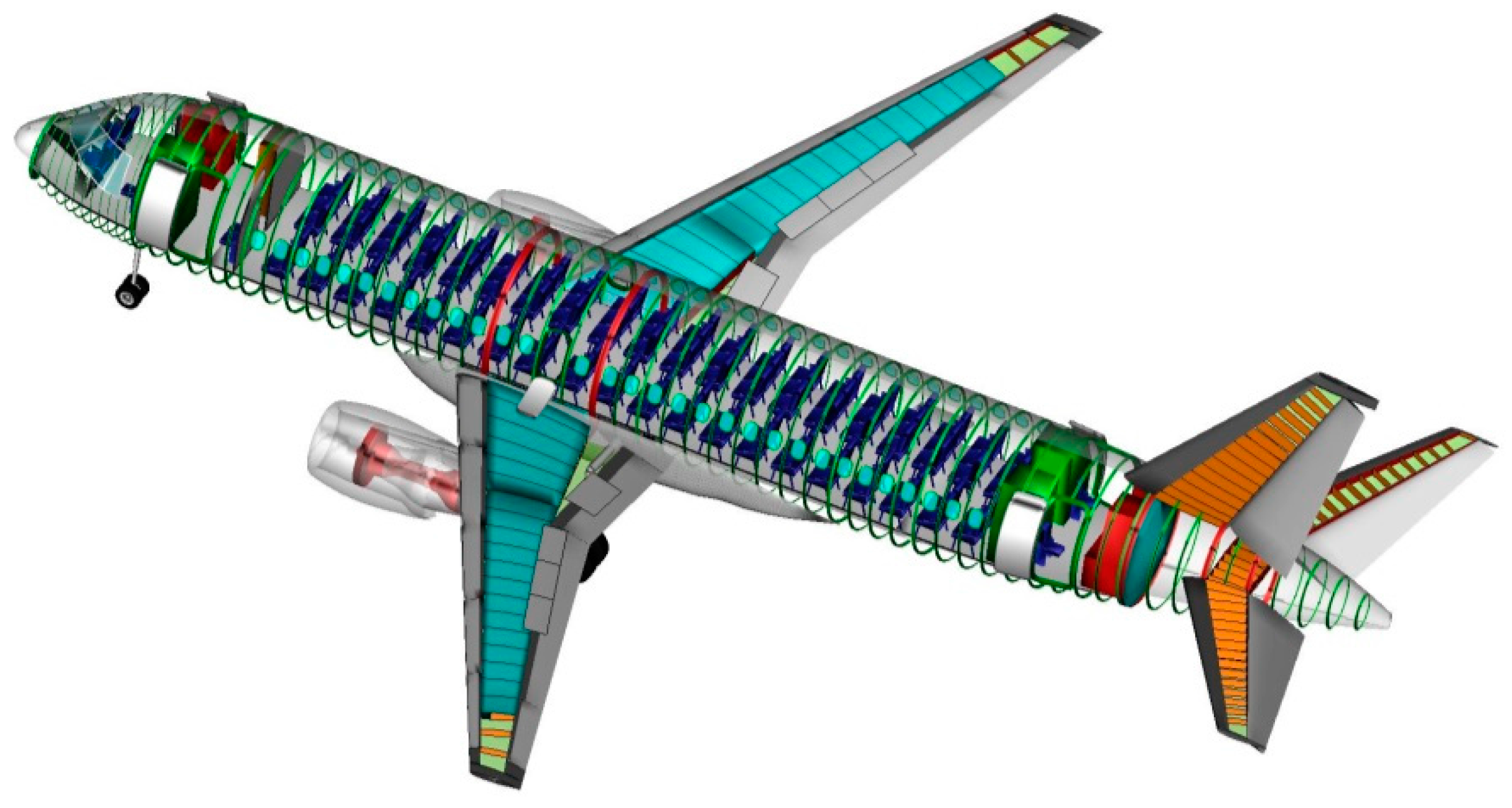
A current university project of Technische Universität Braunschweig (TU Braunschweig), the Collaborative Research Centre 880 (CRC 880) funded by Deutsche Forschungsgemeinschaft (DFG) unites a number of university institutes in aircraft research. The scope is future aircraft design. Detailed data, including turbofan engines for a 100 pax plane, have already been gathered. This data can be used for dimensioning purposes of future electric aircraft and electric propulsion systems (
Figure 2).
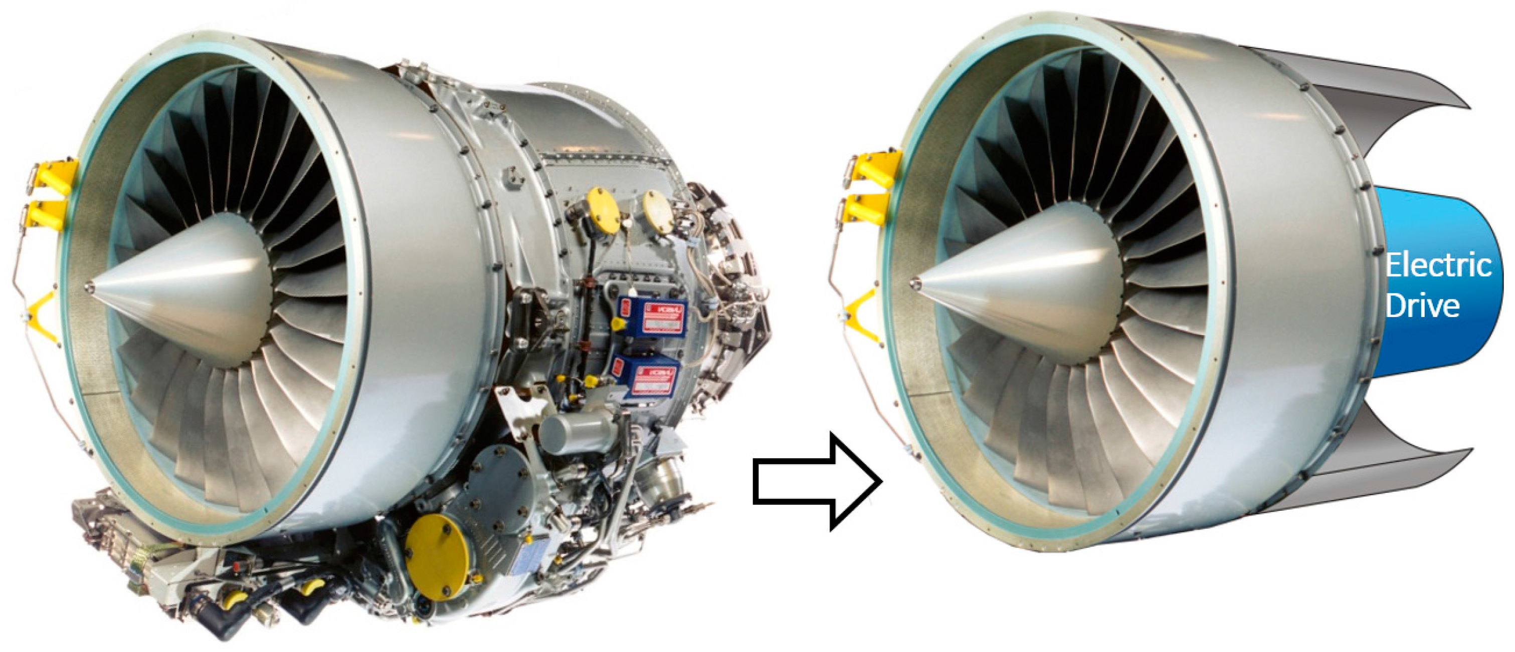
Today, the most efficient aircraft engines are turbofan engines with a high bypass ratio. This type of engine can be found in nearly all commercial aircraft. As an example, consider the 1.1 MW (cruising power) turbofan engine (PW 300 Series, Pratt & Whitney, East Hartford, CT, USA) for a business aircraft. The overall weight is 470 kg, with a fan diameter of 800 mm, and a fan speed of 10,000–11,000 rpm (circumferential speed 466 m/s) [
3,
4] (
Figure 3). At cruising operation, the rotational speed is reduced to 80%, reducing the power output to approximately 30% of the maximum power. The maximum speed of the turbine’s high-pressure part is 27,500 rpm, driving the compressor, whereas the low-pressure part of the expansion turbine is directly coupled to the fan. To adapt to the fan speed, a gearbox can be used (geared turbofan). This one-stage, low-weight planetary gear is calculated as 0.005 kg/kW. By exchanging the turbine for an electrical drive, we obtain an “electrofan” engine as a competing system that allows carbon dioxide-free operation of airplanes, which is one of the big challenges in the future of air transport.
Assuming the electrofans of the aircraft are operated on a DC bus, each electric drive will include an electrical machine and an inverter. They should not increase the weight of the engine at a comparable power rating, having an extremely lightweight, often used electrical machine is essential. Additionally, the difference between apparent power consumption and real power output should be as small as possible to minimize the size and weight of the inverter.
As design approach, we see two main areas of focus: a direct drive without a gearbox for the fan as the simplest approach, and a high-speed drive of approximately the same speed as an actual turbine, equipped with a gearbox as used on geared turbofans. Technical challenges will include the overload capacity of the electric drive during take-off and the material fatigue over the lifetime of the aircraft. Operating a fluid flow engine, we have a quadratic function between torque and speed, so exploiting the advantages of field weakening (reduced power rating) will not be possible.
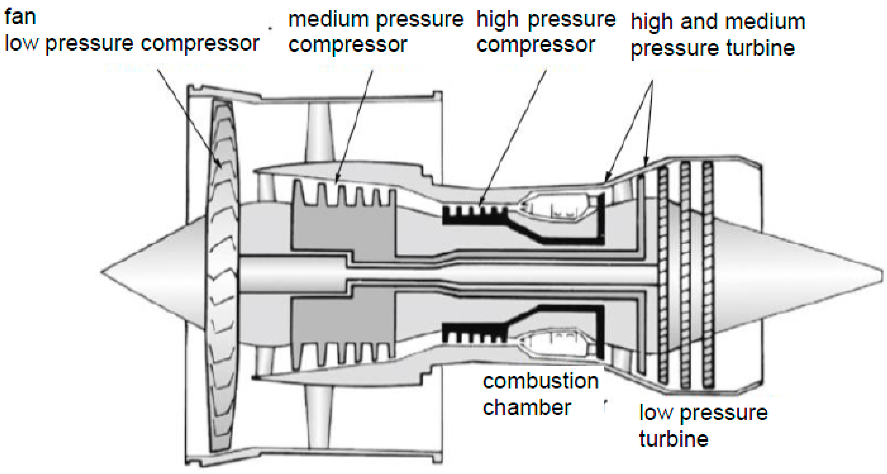
In
Figure 4, a schematic overview of a modern turbofan engine is shown. Before changing to all-electric aircraft, more-electric aircraft are likely to be developed. As independently rotating spools are implemented to develop torque or to generate power, electrifying a part of the spools is a possible method to create a highly integrated hybrid turbofan engine.
2. Design Space for Aviation Drives
The electrical machine for aviation must be thermally robust and highly efficient to limit the energy consumption and cooling [
7]. A close dependency exists between energy consumption and machine weight. The machine’s weight originates from the mass of the soft-magnetic components that can be reduced by the higher saturation of the material (i.e., iron or cobalt-iron), and the weight of the winding that can be reduced by higher current densities or the use of aluminium instead of copper. Higher losses in the machine must be covered by increased power consumption, thus raising either battery mass or tank volume, when using fuel cells.
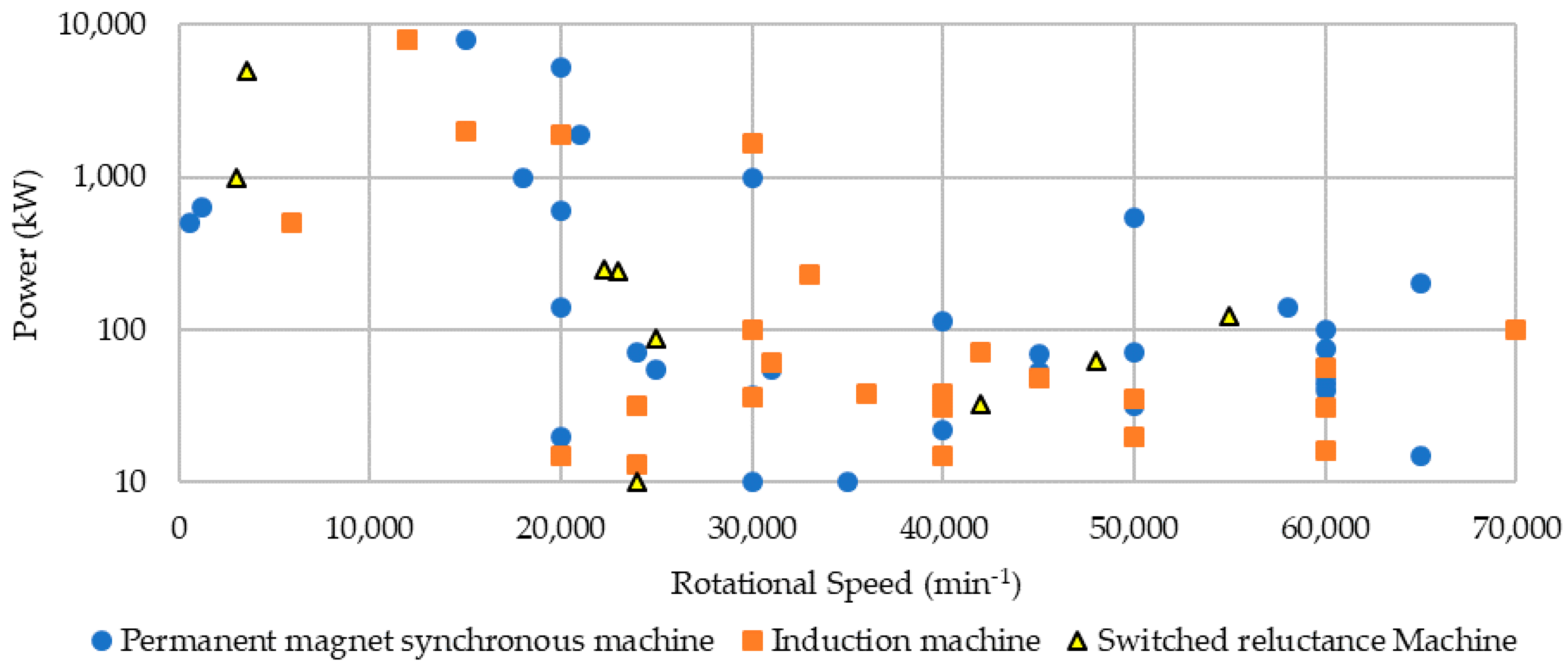
Different electrical machine concepts could be used to design an all-electric aircraft. Especially for the main engine, a motor is needed that has either high torque density or high-power density. Krishnan and Bharadwaj [
7] list three possible machine concepts that could achieve these goals: (1) permanent magnet synchronous machine (PMSM), (2) switched reluctance machine (SRM), and (3) cage induction machine (IM). In this paper, we compare these three concepts and the electrically excited synchronous machine (ESM) as well.
Table 1 shows the different key characteristics of the aforementioned electrical machine concepts.
Given this comparison, the permanent magnet synchronous machine is the most feasible solution for implementation into an aircraft. Ganev [
8], however, worked under the premise that the machines will be used as auxiliary units to the main engine, e.g., by replacing hydraulic pumps. For higher power demands in the megawatt range, this comparison may not be fully applicable. Also, characteristics like functional safety, and a comparison of the machine concepts regarding the constant power range, are missing. Arkkio et al. [
9], Binder et al. [
10], and Gerada et al. [
11] compared many designs and concepts over a wide power range.
Figure 5 shows many of the highlighted machine designs as output power over their rotational speed.
The general suitability of a machine design can be described in different ways. Often, the power to weight ratio is used. As this number compares the power to the overall weight, high-speed designs have an advantage, since they need a much lower volume for the same power output. The reason why this value was not used to quantify the following machine designs is that, apart from the one mentioned before, this value is greatly dependent on the used materials, and the used weight includes the housing and bearings. As these differ considerably depending on the application, the power to weight ratio does not allow a fair comparison; an alternative ratio would be the power to volume ratio. This value is just slightly more suitable, as it is not material-dependent but does not consider cut-outs in the rotor body, which are used in machines with high bore diameters to reduce the weight and the moment of inertia. A more fitting choice is Esson’s number [
12], as it incorporates the rotational speed into the power to volume ratio, thus providing a torque-to-volume ratio:
where
PN is the rated power,
Di is the bore diameter,
lfe is the length of the active parts, and
nN is the rated rotational speed. This number describes the torque density of the machine and allows a more distinctive view of a wide range of rotational speeds.
2.1. Machine Concepts
In the following, different electrical machine concepts are compared in terms of their usability for a multi-megawatt motor design.
2.1.1. Electrically Excited Synchronous Machines
Synchronous machines equipped with field windings in the rotor are used for a variety of applications in the multi-megawatt range. These machines are mostly used at relatively low rotational speeds, up to 15,000 rpm, as generators at power plants or as motors, such as for turbo compressors. With respect to the mechanical stability of the rotor system, electrically excited synchronous machines achieve higher circumferential speeds than induction machines, since they can be manufactured with solid rotors that can also be used as a start-up cage in many cases. However, for aircraft applications, synchronous machines with field winding are not used because the excitation is mostly realized through brushes and slip rings that need to be maintained regularly. This is even more true if such a machine is designed as a high-speed concept, as higher rotational speed increases the abrasion of the brushes. Additionally, the rated speed approaches the first bending frequency, which serves as another limit [
8,
13].
2.1.2. Reluctance Machines
Reluctance machines, especially synchronous reluctance machines, have received increased attention because of the developments in inverter technology and the absence of permanent magnets or a rotor winding. The latter is the reason for low rotor losses compared to induction motors, and better fault management due to the lack of permanent magnets that could demagnetize or induce voltages above the DC-link voltage when the machine operates in the field weakening range. Additionally, reluctance machines are cheap to produce because of the lack of a rotor cage, field winding, and permanent magnets. Nonetheless, the dimensions of both synchronous reluctance machines and switched reluctance machines are about 50% larger than those of PM synchronous machines due to the reactive power needed [
14].
2.1.3. Induction Machines
Many applications use induction machines (IM) because of their overall robustness and low production cost. The absence of permanent magnets benefits the IM in the field weakening range. In comparison to reluctance machines, IMs have a higher power factor making the machine suitable for high-speed operation. The critical aspects of the machine design include the mechanical stress of the cage, especially for its end-rings, and the thermal evaluation as a result of the conducting rotor parts [
15]. Different rotor designs have been developed and compared, but for high power applications with restricted installation space and the low weight requirement, laminated and caged rotors are most feasible [
16].
Caprio et al. [
15] presented a 2 MW high-speed flywheel machine that operates at 15,000 rpm with an Esson’s number of 2.6 kW·min/m
3. The challenge of the high rotational speed lies in the mechanical design of the rotor. At the high circumferential speed of 290 m/s, the end-ring design and the mechanical stress at the rotor ends and its joints to the cage are crucial. Mechanical and thermal aspects must be considered to choose the best design and material.
During the 1990s, the first high-speed high-power electrical machines were developed for industry applications, such as compressor drives in refineries. Therefore, Wood et al. [
17] designed an induction motor with a solid rotor and aluminium bars that operates at 11,000 rpm at a power output of 2.6 MW. The Esson’s number achieved with this design was 1.9 kW·min/m
3. In their design, the large bearing span of 2.4 m required special attention to the rotor dynamics. A simulation was completed to investigate the critical bending frequencies and the torsional resonance frequencies.
2.1.4. Permanent Magnet Synchronous Machine
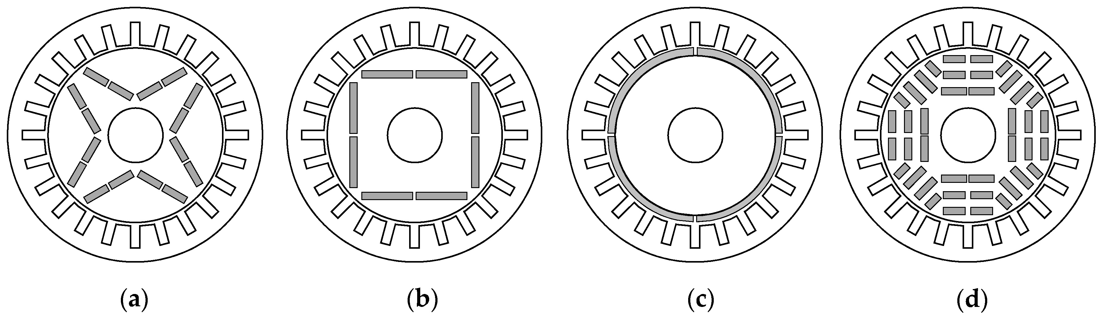
Permanent magnet synchronous machines (PMSM) are widely used and are being applied in an increasing number of fields, including electromobility, railway traction, ship propulsion, generators etc., since the missing field winding allows for higher efficiency, higher power density, lower heat production in the rotor, and sensorless control, although the magnets are comparatively expensive. Nonetheless, the absence of an exciter machine with rotating rectifier or slip rings to supply the field winding means less maintenance is required. The different rotor designs for permanent magnet excited machines include: v-shaped buried magnets, beam-like buried magnets, surface-mounted magnets, or multi-layer buried magnets (
Figure 6).
Each has its benefits concerning flux density, flux distribution, mechanical stability, or weight. Bacaro et al. [
18] compared these different rotor concepts for an internal permanent magnet synchronous machine that was used as railway traction drive. The power output was 630 kW and it operated at 1200 rpm, categorizing it as a low-speed machine with a low circumferential speed of 22 m/s. As is the case for most mobility applications, the installation space was limited, resulting in an active length of 500 mm. Esson’s number for this PMSM was 8.6 kW·min/m
3, which, in comparison, is considerably higher than the highlighted induction machines. In the end, the chosen rotor design was the buried multi-layer design with three layers, where the amount of magnet material was optimized to determine the best ratio of copper and iron losses.
Higher rotational speeds combined with high power requirements lead to electrical machine designs with high rotor diameters and thus high circumferential speeds. Zhang et al. [
19] investigated different surface magnet concepts and filler materials for the pole gap to ensure safe operation by developing a hybrid rotor armor design. The machine rotates at 18,000 rpm and delivers 1.12 MW. With an active length of 400 mm, its Esson’s number is 6.4 kW·min/m
3.
2.2. Concepts and Design Choice
For travel ranges of several thousand kilometres, current aircraft engines are mostly high bypass ratio or ultra-high bypass ratio concepts. Given the specifications of the PW305A, manufactured by Pratt and Whitney and used in the Lear Jet 60 by Bombardier [
4], a direct-driven engine would need a motor at the same speed as the fan. A rotational speed of 10,608 rpm is not a typical low-speed design. According to
Figure 5, both permanent magnet synchronous machines and induction machines would be feasible solutions. The use of an additional gear box would broaden the possibilities.
For a high-speed machine concept, the induction motor with laminated or solid rotor core and a squirrel-cage, depending on the rated power, is most suitable according to
Section 2.1.3, due to its strength in the field weakening range and the low maintenance requirements. The optimal operating point with maximum efficiency occurs at a higher rotational speed for IM than the PMSM, which makes it the better choice for high-speed operation by exploiting the field weakening range.
The direct-driven solution should incorporate a permanent magnet synchronous machine, since the optimal efficiency of a PMSM lies within the constant flux range that would require a high DC-link voltage to be used given the demand of the high rotational speeds. Furthermore, in the field weakening range, the induced voltage is higher than the maximum allowable DC-link voltage, resulting in additional safety measures being required. High centrifugal forces caused by a high bore diameter can be covered through rotor armoring, which will be described below.
3. Winding Technology
The armature winding is one of the key components in the electromechanical energy conversion process. The number of turns and the number of pole pairs significantly impact the shape of the speed-torque operation map. To achieve a high overall system efficiency, these parameters have to be chosen to meet the system requirements of the aircraft as well as the needs of the power electronics. Furthermore, the winding production method directly influences the winding properties like the slot filling factor and the end-winding length. The former affects the electrical and thermal resistance and therefore the losses, whereas the latter determines the available space for energy conversion, which in turn determines the power density of the overall system.
In addition to conventional round wires, by using rectangular wire windings, the slot fill factor can be significantly increased, resulting in smaller motors with excellent performance. The most popular approach is rectangular wire, which is well-suited to and widely used for mass production, bent into a hairpin shape on one axial side of the stator. The ends of the wire on the other side are welded to form connected coils in a wave shape [
20]. Large copper cross-sections may lead to higher losses if the slots are exposed to higher frequencies. Loss effects on the system must be examined and balanced in a holistic design.
However, in addition to a proper pole pair number, winding turns, and a suitable production technology, additional degrees of freedom exist: by increasing the number of phases, the fundamental wave in a machine can be further strengthened compared to a three-phase system, which results in higher torque and efficiency. Furthermore, certain higher order harmonics can be significantly reduced or even completely eliminated using this approach. These higher harmonic orders are parasitic in nature, since they do not contribute to the constant torque, but their occurrence leads to an increase in iron losses, eddy current losses in magnets, local saturation, pulsating torque, noise, and vibrations. Moreover, using more than three phases improves fault tolerance by adding redundancy to the system.
4. Materials
The selection of materials used for an electrical machine is an important aspect of each design process. The following sections will highlight the different components of an electrical machine in terms of the different concepts to show the state-of-the-art material choices as well as some other materials as references for comparison.
4.1. Magnetically Hard Materials
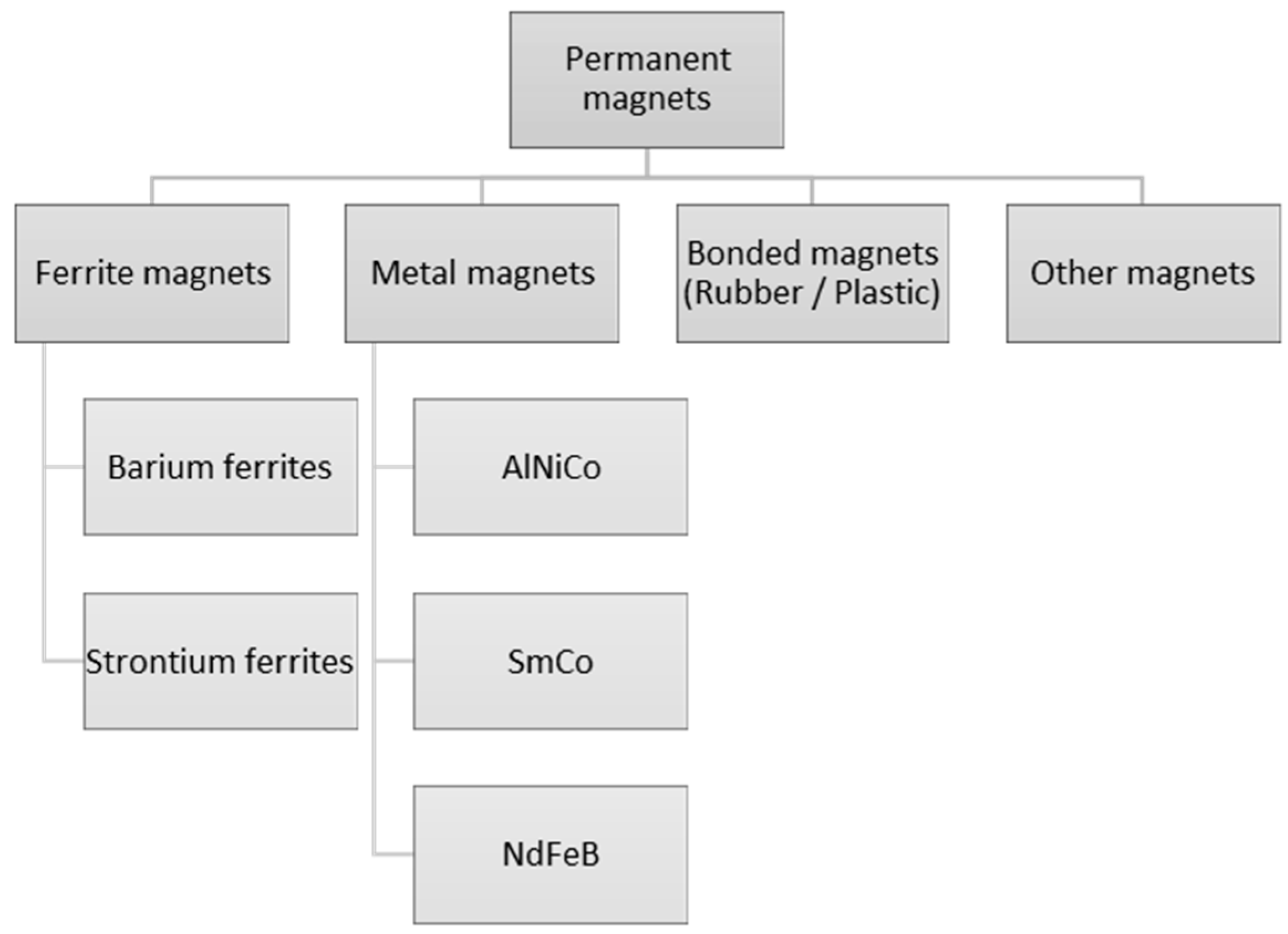
Magnetically hard materials supply the rotor field in permanent magnet synchronous machines.
Figure 7 shows the different magnet materials that are currently used in electrical machines. A wide variety of materials have been developed since the 1990s, allowing permanent magnet machines to be viable for a variety of applications [
21]. Rare earth magnets, with their high energy densities and their high remanence field strengths, are especially used in high-efficiency electrical machines with high power factors, such as in wind turbine generators or traction drives for vehicles. Synchronous machines with high rotational speeds are prone to demagnetization leading to failure, which is dependent on the coercive field strength.
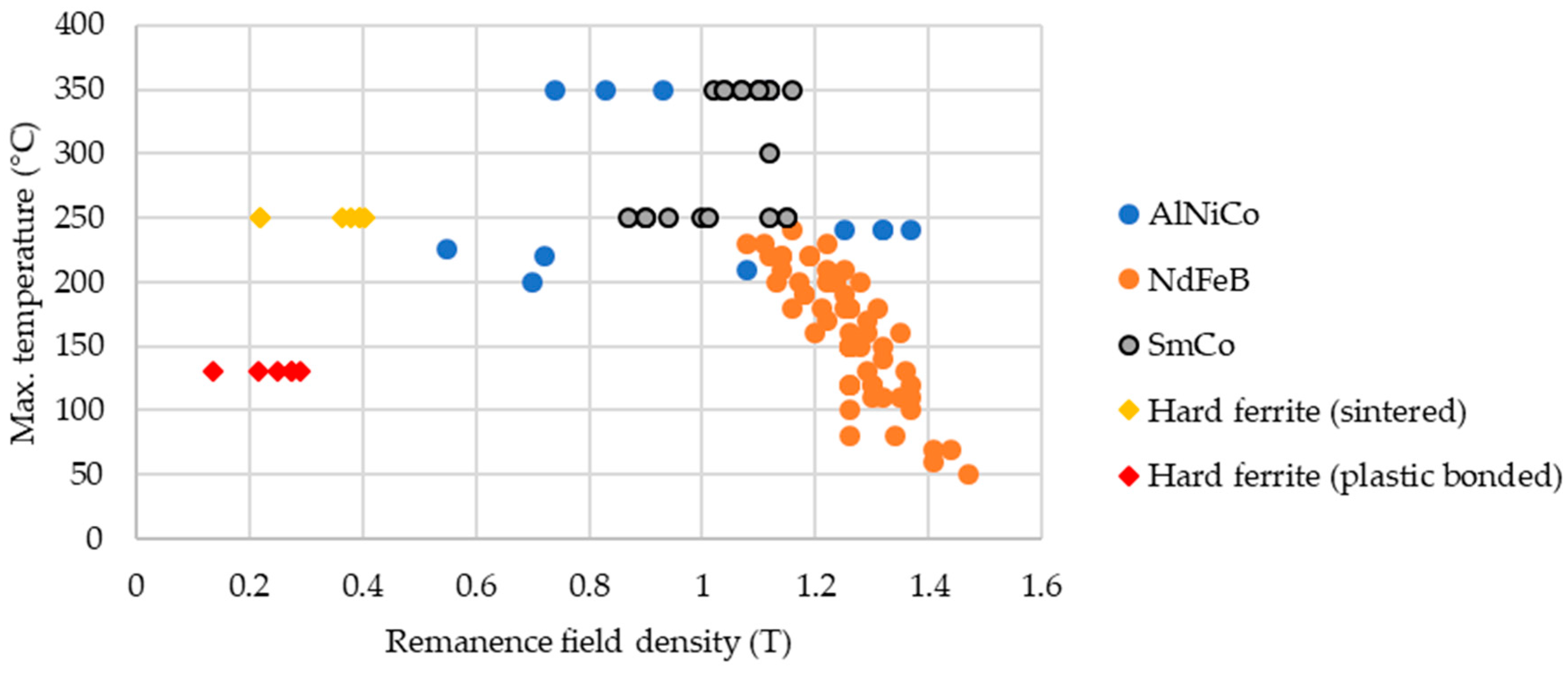
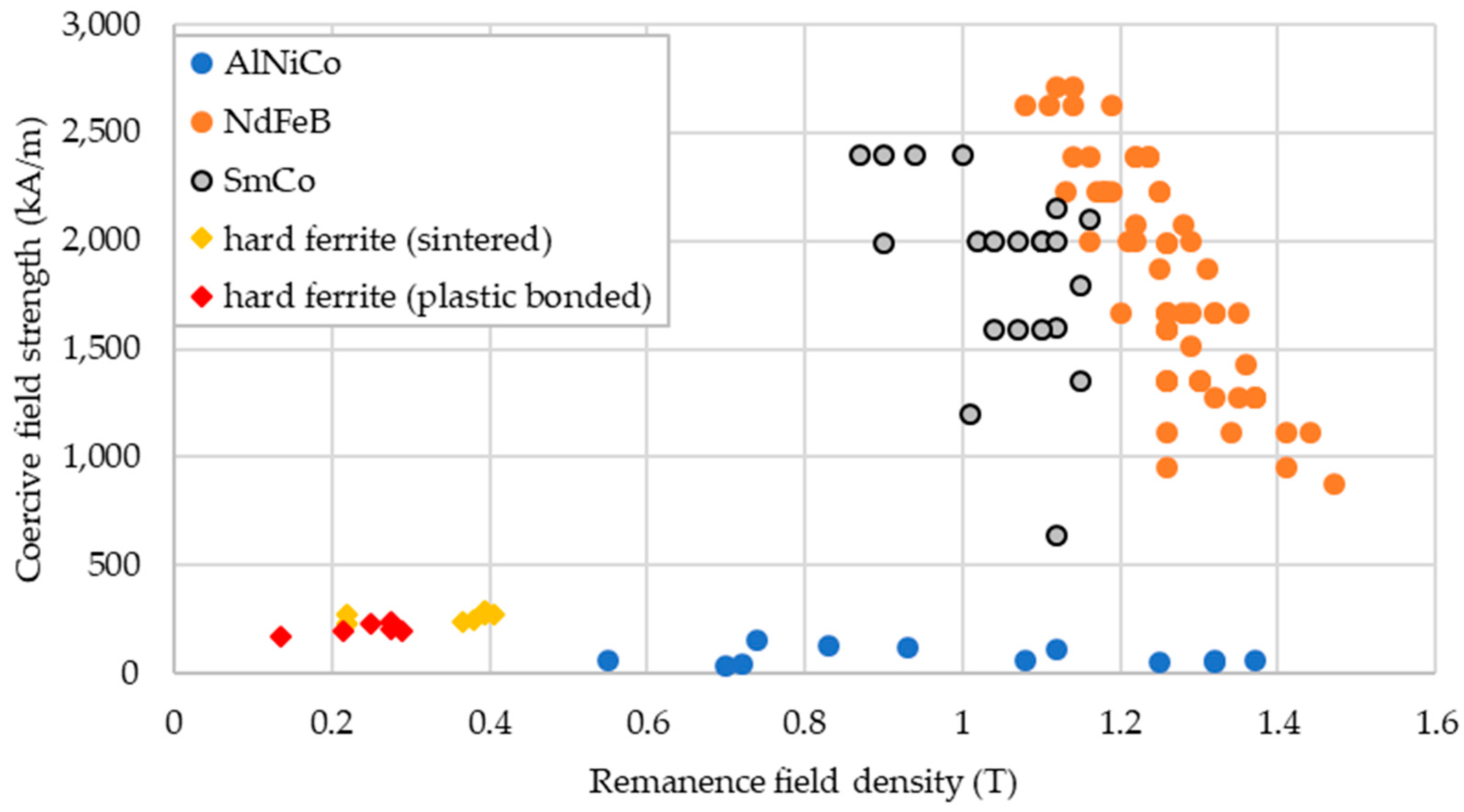
Figure 8 shows different permanent magnets and their coercive field strengths plotted against their remanence flux densities [
22,
23,
24,
25,
26]. The plot demonstrates why hard ferrites are not used in high-efficiency applications. AlNiCo magnets are not suitable either, since they are highly susceptible to demagnetize during failure. Therefore, the rare earth materials NdFeB and SmCo, in different specifications, are the best choices from a technical standpoint, even though they are rather expensive.
Depending on the application, high mechanical strength, high energy density, or a wide temperature range are required in the magnetically hard materials.
Figure 9 provides an overview of magnetically hard materials and their maximum operating temperatures.
Comparing NdFeB and SmCo, the differences are their mechanical parameters for tensile strength and compressive strength. The SmCo variant is much more viable for high-speed motors, particularly when the rotor armor exerts pressure on the underlying surface-mounted permanent magnets.
4.2. Magnetically Soft Materials
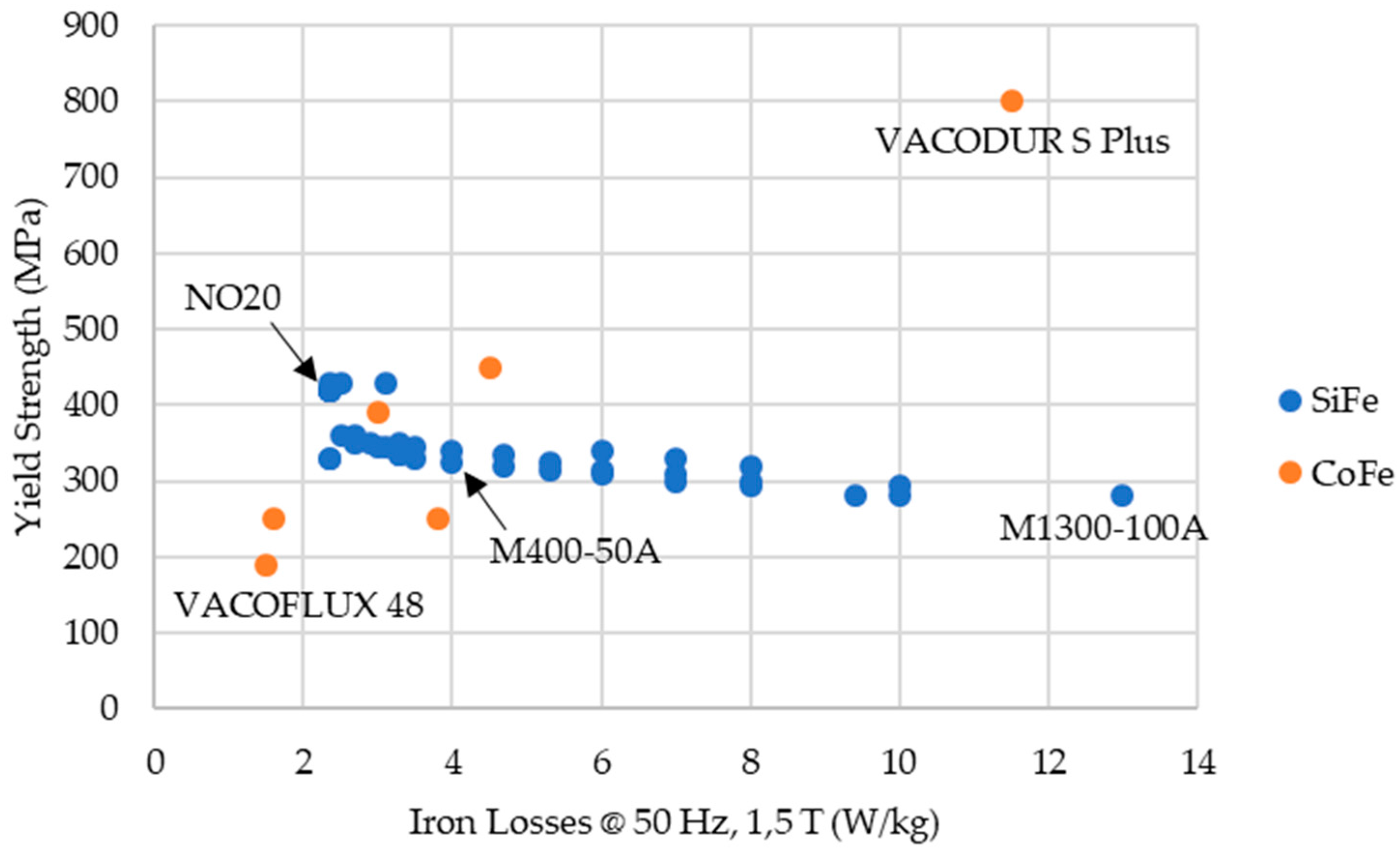
Magnetically soft materials, and electrical sheets in particular, are another high-tech component of electrical machines. Given the increasing demand for efficiency and the growing interest in high-speed motors, efforts have been made to develop new and better alloys. These consist mostly of iron and a varying percentage of either silicon or cobalt and other metals. Depending on the requirements, high saturation magnetization, high yield strength, and/or low specific iron losses is desired. For high-speed machines, a material with good values for all three properties would be optimal but this is impossible. Cobalt-iron (CoFe) sheets are the best choice for high saturation magnetization. Unfortunately, it has poor mechanical characteristics.
Figure 10 shows several electrical sheet materials and their yield strength against the specific iron loss [
27] with VACOFLUX and VACODUR as specialized CoFe-materials produced by VACUUMSCHMELZE GmbH & Co. KG, Hanau, Germany [
28].
The thickest sheets (1 mm) exhibit the highest losses. The sheet thickness is decreased to reduce the eddy current losses. In conjunction with the high saturation magnetization, the cobalt-iron materials exist in different variations. For example, VACOFLUX 48 has very low specific losses and is available in different thicknesses, from less than 0.1 mm to 0.5 mm. VACODUR, on the other hand, is the choice for high mechanical requirements due to its high yield strength. The iron losses in the rotor are much lower than the loss in the stator, thus a lamination material with higher specific iron loss but higher yield strength can be chosen. For high-power applications such as aircraft, the use of different materials for the stator and rotor could be advantageous.
During the design phase of an electrical machine, the iron losses and, even more importantly, the mechanical stability of the rotor system, have to be considered, but these are not the only restrictions. Especially for aircraft applications, the weight must be considered. Most silicon-iron sheets have a density of approximately 7800 kg/m
3. The cobalt in the CoFe sheets is about 50%, resulting in densities around 8120 kg/m
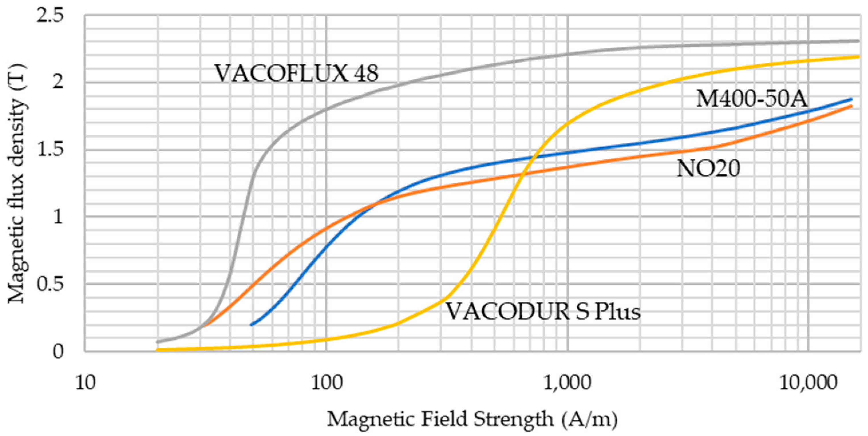
3, thus making the electrical machine heavier. Usually, this disadvantage is countered by the fact that these sheets have a high saturation magnetization. Hence, less material is needed to create the same amount of magnetic flux (
Figure 11). For future electrical machine designs, which are in need of a high power to weight ratio or a high torque to weight ratio, these cobalt-iron alloys must provide the same magnetic flux but with lower material in the yokes and teeth.
Another material option with low eddy current losses is soft magnetic composites (SMC) that consist of small iron particles that are isolated by a thin insulation layer from each other. As the name suggests, this composite is moulded. Therefore, its use in mechanically challenging applications is not currently advisable.
4.3. Conductors
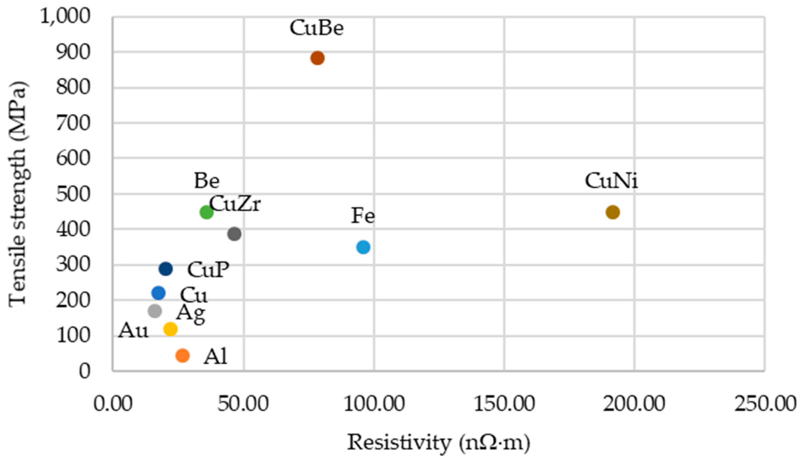
There are two types of conductors in an electrical machine: the stator winding that mostly consists of copper and either a rotor winding, which is copper in most cases, or the cage of an induction motor. For most industrial applications, the cage bars and end-rings of motors are manufactured from aluminium, since it has a relatively low resistivity, and is relatively cheap and easy to die cast. The advantages over copper and copper alloys are the cost and the low density, which reduces the moment of inertia, whereas its conductivity is relatively high compared to many other materials. For the stator winding, the number of possible alternatives to copper, like silver and gold, are very limited, being generally too expensive for too little a technical advantage. As we have excluded the electrically excited synchronous machines above, the main field of research on feasible conductor materials focuses on the cage of induction machines.
Figure 12 shows the different materials with their resistivity against their tensile strength [
29]. A copper cage seems to be most suitable for high-speed operations, but other materials may be suitable, like phosphorus-copper, beryllium, or possibly aluminium alloys that have relatively high conductivity and high tensile strength. Induction motors need as small an air-gap as possible. Therefore, using rotor armor should be avoided. With these materials and alloys combined with fitting electrical sheets, a high-speed rotor with high power density can be designed.
4.4. Superconductors
Alternatives to classic conductor materials like copper are superconductors. Superconductors have nearly no electrical resistance if operated below a certain threshold temperature. Depending on the threshold, the superconductors are further separated into superconductors and high-temperature superconductors (HTS). The name HTS was created for the first superconductors with a threshold temperature above approximately 20 K. The reason these materials are superconducting is not yet fully understood [
30,
31]. The most common high-temperature superconductors are composed of rare earth, barium, and copper oxides (YBCO) that have a temperature threshold of 93 K and are usually operated at 70 K. The material is available either as bulk or as tape conductor several kilometers in length. Some of the currently used HTS and their threshold temperatures are shown in
Table 2.
Even at high temperatures of about −148 °C (125 K), cooling is a challenge. Some of the proposals include liquid hydrogen at 20 K or liquid neon at 27 K [
33]. Incorporating this system into an aircraft would be difficult but the weight and size of the machine would be reduced by 70% [
34]. Hence, several superconducting machines have been designed to date. Applications range from ship propulsion [
35] to all-electric aircraft proposals [
36], achieving power to weight ratios of up to 8 kW/kg and torque densities of up to 2 Nm/kg in the power range of single megawatts or single MVA, respectively. The machines are either electrically excited by HTS-wound rotors or fitted with HTS magnets.
5. Special Issues in Design
In this section, crucial special issues and demands concerning high performance and lightweight machines are addressed and exemplified.
5.1. Winding Design
A general and deterministic method to determine multi-phase and multi-layer winding topologies has been introduced [
37,
38,
39]. In this approach, an N-slot machine and N-phase winding (or N/2-phase if N is an even integer) arrangement, with an ideal current sheet space harmonics spectrum, was considered as a starting point. However, from a practical point of view, the proper choice of a winding usually is obtained from the choice of a phase number smaller than N
Figure 13.
For a given number of phases, pole pairs, and slots, Cai et al. [
37] demonstrated that an optimal MMF spectrum exists as the best approximation of the ideal spectrum that can be determined by solving a linear equation system. In this case, the best approximation means the unavoidable smallest loss in fundamental winding factor and the smallest distortion of MMF space harmonics spectrum due to the choice of a
ms smaller than N. The resulting windings are usually the multi-layer type and probably contain coils with different numbers of turns. This method is further improved by considering and exploiting symmetry as one of the most important properties of symmetrical multi-phase windings [
38,
39].
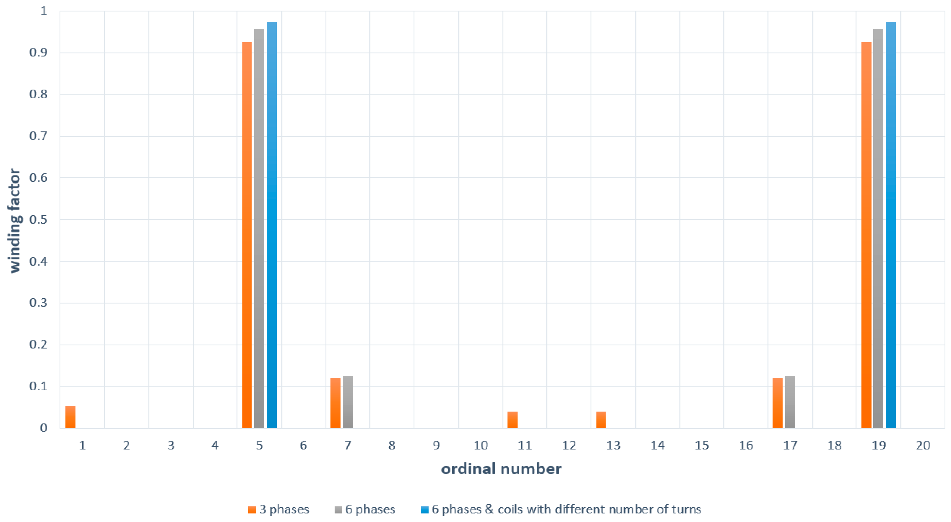
In Domann and Henke [
40], a machine featuring a six-phase winding configuration was built. The winding was considered superior to several three-phase windings with respect to copper and iron losses. The spectrum of this winding was further improved by implementing multi-layer topology with coils of different numbers of turns and coil pitches [
41]. Compared to the winding spectra [
40], the seventh harmonic winding factor is not shown, further increasing the winding factor of the working harmonic.
5.2. Rotor Armoring
Synchronous machines with very high rotational speeds, and thus high circumferential speeds, often use additional rotor armoring to secure the permanent magnets against centrifugal force. In
Table 3, several rotor armor materials are shown with their respective mechanical properties [
42].
The values of the tensile strength and the Young’s modulus for fibre materials are orthotropic values in the direction of the fibres. In general, a material with high tensile strength would be chosen to reduce the thickness of the armor. However, the differences in the Young’s modulus must be considered, especially if the machine has a very tight air-gap. The lower the Young’s modulus, the higher the elongation when under stress. Apart from countering the centrifugal force, the rotor armor should help to hold the components of the rotor in place. If the radial elongation is too high, the rotor could potentially close the distance of the air-gap and rub against the stator, which would damage the armor.
Other important parameters for the design of a rotor armor include the thermal expansion coefficient, resistivity, and magnetic permeability. As shown in
Table 3, the thermal expansion coefficients of the chosen armor materials differ not only in value but in sign, meaning that carbon fibre and Kevlar shrink with increasing temperature. The shrinking would increase the stress on the armor but would counteract the elongation due to the centrifugal force.
The resistivity and the magnetic permeability are needed to estimate the potential eddy current losses in the armor due to the current harmonics in the stator winding and field harmonics in the air-gap. Compound materials have an additional advantage, since the fibres are small and act like a laminated core, which reduces eddy current losses, thus resulting in lower heat generation in the armor.
5.3. Mechanical and Thermal Aspects
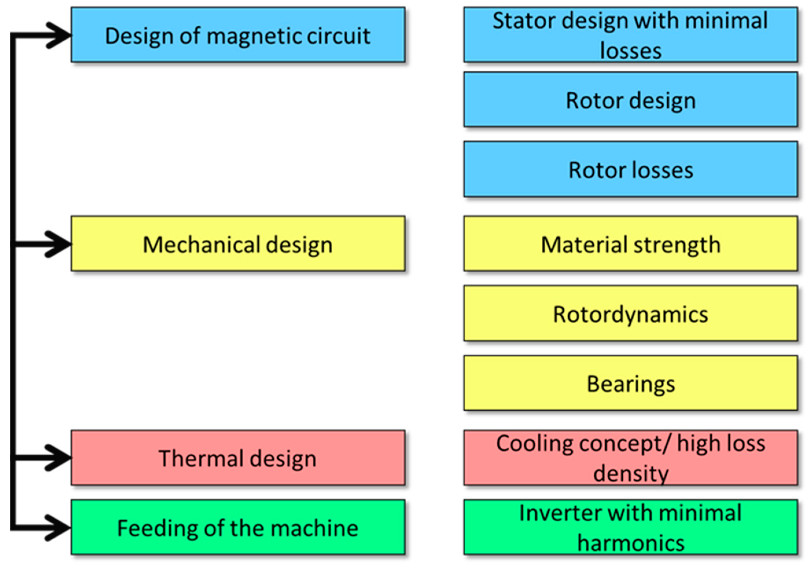
The design of high-speed machines is dominated by a close interaction between electromagnetic, mechanical, and thermal parameters (
Figure 14).
As the size of an electrical machine is mainly determined by the torque, a high-speed machine is of comparable small size if the speed increases. However, for a certain rated power, the specific losses increase due to higher additional losses in the iron and eddy current losses in the winding. So, an increasing loss density must be expected, which requires more intensive cooling than a conventional machine. If the circumferential speed exceeds approximately 180 m/s, the gas friction losses cannot be neglected and additional measures are necessary. As permanent magnet synchronous machines have very small rotor losses, they are preferable for aviation applications. Proven approaches to handle the additional losses include: (1) sinusoidal flux distribution (surface magnets or protected magnets with reluctance component), (2) distributed winding with low harmonic content, (3) inverter with high switching frequency, thus feeding currents with low harmonic content, and (4) advanced cooling concepts.
In
Section 5.2, an overview of different available banding materials and their mechanical parameters was provided. In the following section, the use of rotor armoring will be further explained. The mechanical stabilization of a surface-mounted permanent magnet high-speed synchronous machine requires the construction of a banding made from carbon fibre located in the air-gap. As the magnetic flux density decreases with increasing air-gap, the carbon fibre banding should be as thin as possible. The carbon fibre usually forms a unidirectionally wound cylinder that is resin-impregnated (CFRP) and maintains the rotor structure under considerably high pressure, so that even at testing speed, no “lift-off” of the permanent magnets can occur. By applying this measure, uncontrollable unbalance of the rotor is avoided.
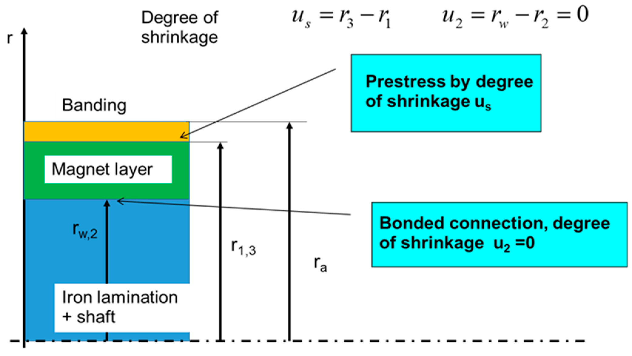
For kinematic equations, a superposition is required of the elastic displacements due to the gap pressures and the centrifugal forces. As a result, the displacements become speed-dependent. The displacements can be calculated from the elastic material properties, considering that the magnet layer and carbon-fibre banding exhibit anisotropic properties. The design process incorporates Hooke’s law for a polar orthotropic material like a unidirectional wound carbon fibre. Even the elastic deformation of a polar orthotropic material can be calculated analytically, thus allowing a quick design process and parameter variation. Knowing all elastic displacements, the necessary degree of shrinkage can be calculated, yielding the gap pressures and the stresses in the components of the interference fit (
Figure 15).
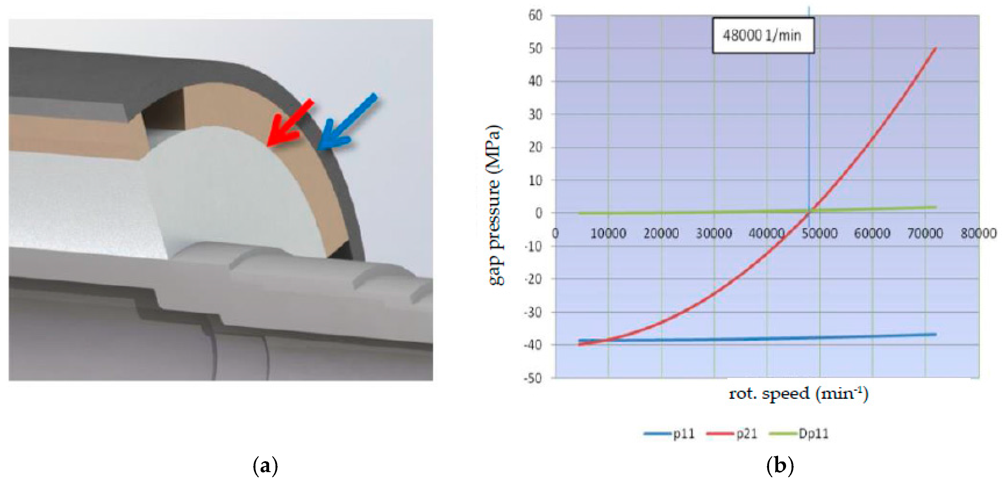
Figure 16 demonstrates the dependency of the radial and stress components in the rotor parts to speed. The compressive stresses in the magnets and the shaft decrease with increasing speed, whereas the radial stress in the CFRP banding is nearly constant. At low speeds, the CFRP banding delivers a compressive stress or a negative pressure value as the banding is prestressed as mentioned above. The dimensioning figure is the gap pressure, which becomes positive beyond the testing speed of 1.2 nominal speed. So, the glue joint between magnets and shaft is guaranteed to stay in the pressure region at all operational speeds.
Due to the high speed of the rotor, the influence of unbalance, and the natural frequencies of the rotor become important. Additionally, the gyroscopic effects influence the natural frequencies of the rotor that become speed-dependent. As unbalance forces increase with the square of the speed, a high-quality balancing of the rotor according to ISO 1940 quality grade G 1 or G 0.4 is necessary.
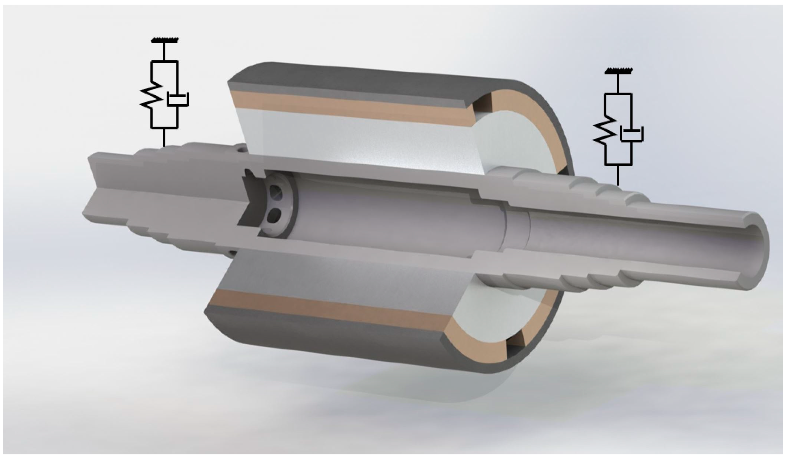
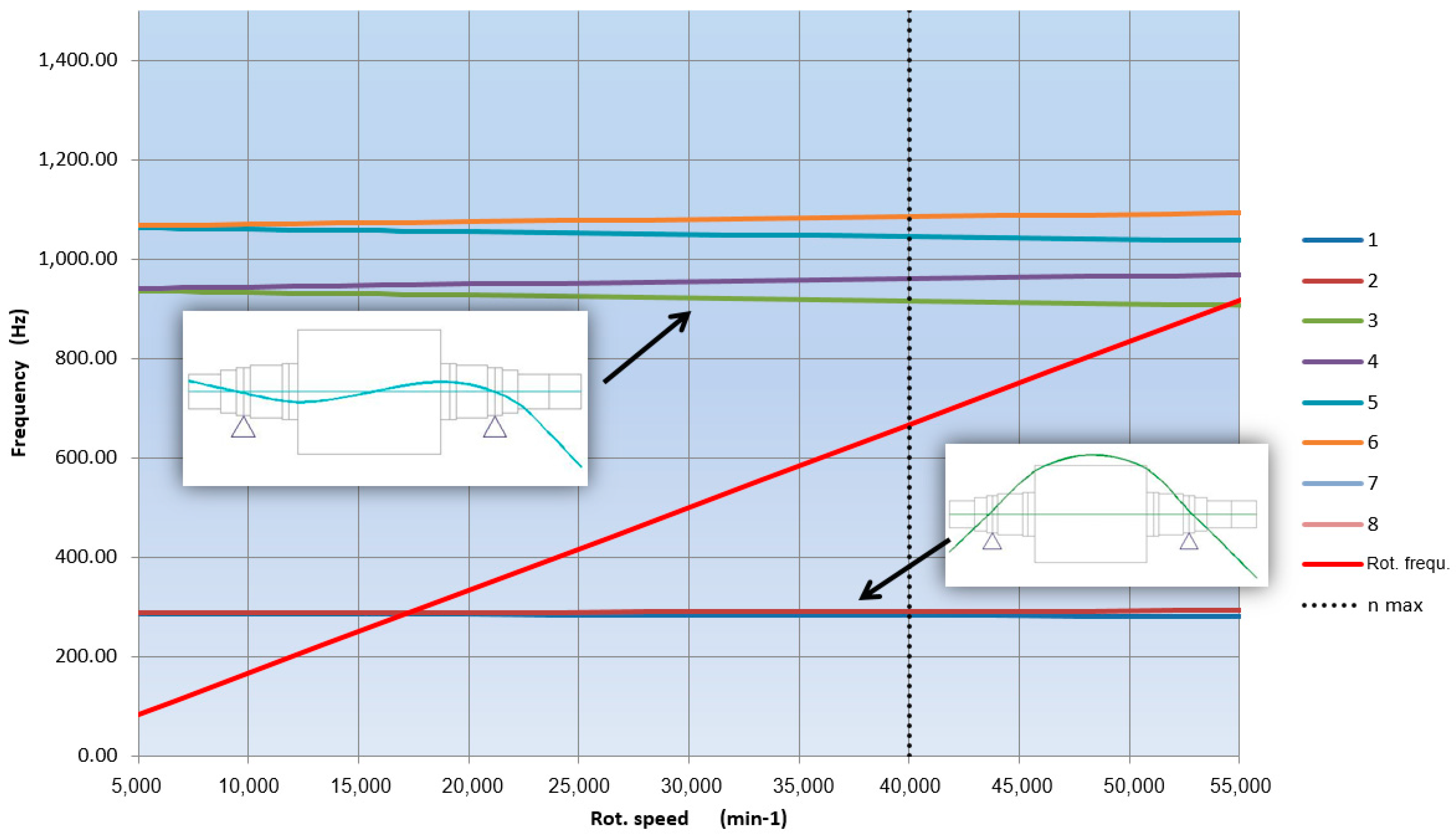
To show the influence of the rotor-dynamics, a rotor model with maximum speed of 40,000 rpm was used. The model shown in
Figure 17 includes all the components that influence the rotor stiffness, and a simple bearing model with radial stiffness of the bearings, and a viscous damping is added. The calculation of the natural frequencies using rotor dynamics software [
41] provides an overview of the vibrational behaviour of the rotor-bearing system. This is depicted in the Campbell diagram (
Figure 18), which shows the influence of speed on the natural frequencies.
The straight red line in
Figure 17 with a slope of one is the speed line that crosses the frequency of the first bending mode of 288 Hz at 17,300 rpm. From there up to the maximum speed, no further natural frequency has to be passed. The second bending mode, at 940 Hz, is well above maximum speed.
This mode also shows the stronger influence of the gyroscopic effects because the natural frequency at zero speed is split by the increasing speed into a forward and backward mode. Whereas the forward mode always stiffens the system, the backward mode reduces the natural frequency with increasing speed. If the speed of the machine is increasing and the rotational speed reaches 17,300 min–1, the rotor passes its critical speed and rotates at the resonance frequency of the bending mode. The effect of this state can be further examined to determine the oscillation velocity and displacement. To reduce the amplitudes, several measures can be taken such as reducing the bearing stiffness.
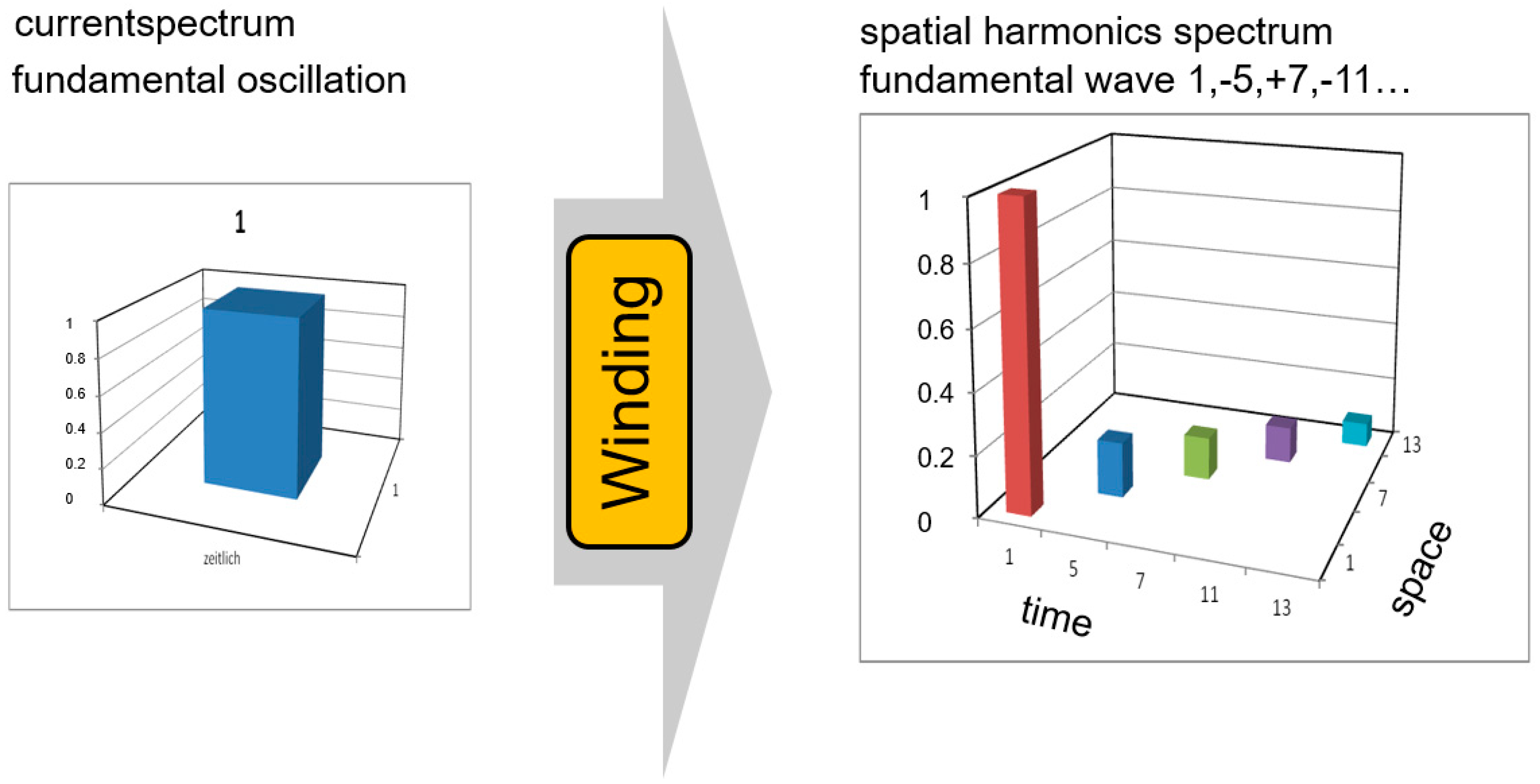
5.4. Rotor Loss Mechanisms
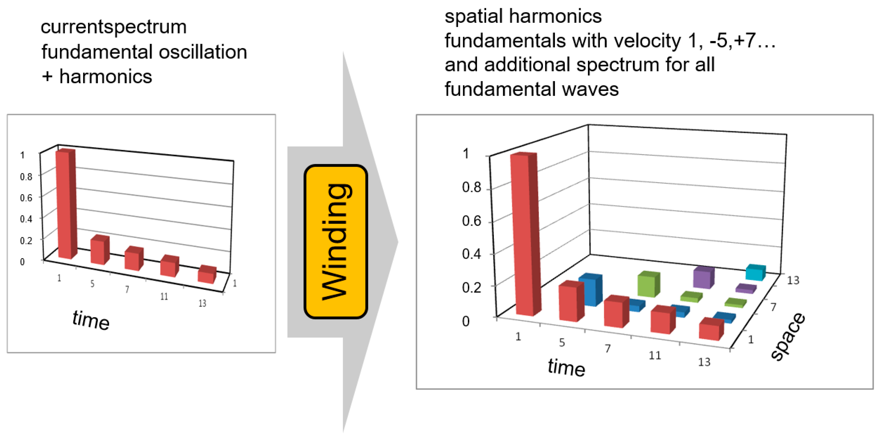
As the inverter is a component that controls the current by a switching pattern like a space vector modulation, the current is not ideally sinusoidal. The inverter contains the fundamental frequency and a spectrum of higher harmonics. Each harmonic oscillation of the current is transformed by the machine winding into a spectrum of waves containing the fundamental wave and its higher harmonics (
Figure 19 and
Figure 20). The winding of a real electrical machine is placed into the slots of the stator, usually manufactured equidistant to each other. As the purpose of the electrical winding is to generate an electric loading to produce a magnetic field to generate torque in a rotating electric machine, by distributing discrete conductors in the stator, only discrete parts of a magnetic field can be provided by the stator when moving along the circumference. In an ideal state, the machine would possess a sinusoidal magnetic field, but a real stator consists of discrete distributed conductors that cause ramped magnetic field distributions, and thus the magnetic airgap field offers a spectrum of harmonic waves. Superimposed, these waves result in a magnetic air-gap field, which is quite different from a sinusoidal field. A Fourier-transformation of the magnetic field or the electric loading shows that part of the harmonics travel in the rotational direction of the rotor, and part travel in opposite direction. Furthermore, discrete current feeding by inverters causes an additional spectrum as shown below. Around the bore of a rotating electrical machine, the current loading shows a spectrum of different frequencies and spatial distributions. These phenomena cause additional losses in electrical machines, such as in the magnets, inside the conductors and in the electric sheets.
Due to the higher frequency of the harmonic oscillations, the velocity of the corresponding fundamental waves is much higher than that of the working fundamental wave. That is why these harmonics produce significant losses in the permanent magnets, which in turn can increase the magnet temperature to levels where the magnets are demagnetized by the armature reaction.
For the current harmonics to stay small, the inverter uses the inductance of the machine. However, a high-speed machine with carbon fibre banding has a specifically small inductance, so that a high switching frequency, of preferably more than 20 kHz, is necessary. A protected magnet concept with a small iron layer above the magnets helps to prevent the harmonic waves of the small pole pitch from intruding into the magnets and facilitates the production of the rotor. A protected magnet concept does not help with the fundamental waves of the harmonic oscillations. To reduce these losses in the magnets, subdivisions of the magnets were introduced.
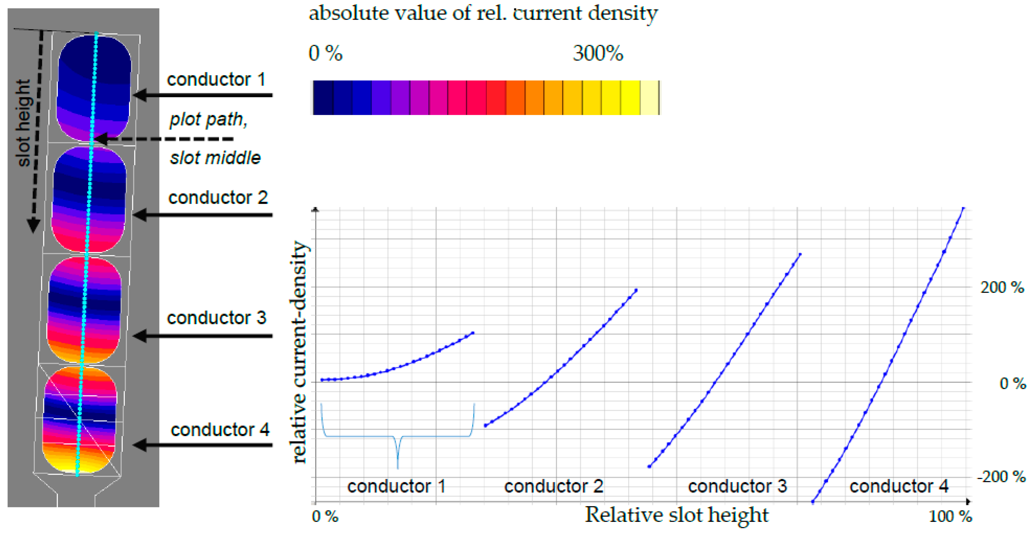
Particularly in electrical high-speed drives, the fundamental frequencies of the revolving magnetic field are much higher than in conventional drives. This can also occur with lower-speed high-torque drives when the machine topology exhibits a higher number of pole pairs. As stated above, the ideal sinusoidal fundamental field distributions develop a number of revolving field waves in inverter-fed machines, incorporating real winding distributions. These additionally-occurring waves move at lower and higher speeds in relation to the fundamental working wave in the stator and rotor, causing iron and copper losses. The aim of designing a compact electrical machine is influenced by the size of the stator slots and amount of copper used. In this regard, a high copper filling factor inside the slot is desired. Highest filling factors can be realized by using solid undivided wires with larger cross-sectional areas. Conversely, skin and proximity effects that arise in copper wires of this type, due to higher frequencies and under influence of oscillating magnetic fields across the slots, strongly contribute to the amount of copper loss, especially under high load conditions. For this reason, the filling factor must be compromised. Dividing the copper wire in the slot considerably reduces eddy currents in this area, and thus contributes to increased efficiency.
Figure 21 provides a graphical impression of the current density in the cross-sectional area of copper conductors, for wires exposed to an alternating magnetic field in the slot of an electrical machine. The highest values of current density occur at the vertical borders of the conductors. To reduce the resulting copper losses, a further division of the conductors is an appropriate measure.
5.5. Direct Liquid-Cooled Winding
For synchronous machines, the maximum allowable winding temperature, and hence the temperature rise in the machine, is the main limiting factor when increasing torque density. Several different approaches are available to enhance the heat dissipation capacity and achieve higher current densities. A higher current density leads to a higher torque density. A higher heat dissipation capacity leads to a lower operating temperature, and thus to reduced winding losses. Typically, medium-sized electrical machines are cooled by either an air cooling jacket or a water jacket.
Normally, electrical machines with water jacket cooling reach current densities of 13–18 A/mm
2 during steady-state operation [
43], strongly depending on the size of the machine. Several thermal resistances, like the resistance from winding to the stator core or from the stator core to the housing [
44], separate the cooling medium of a water jacket from the heat source. The aim of the novel approach presented by Wohlers et al. [
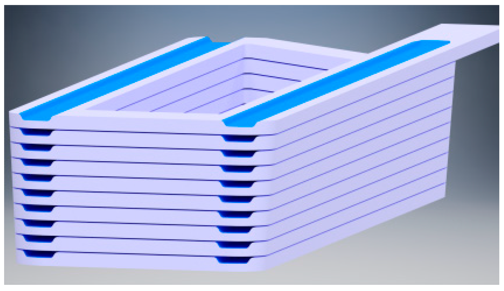
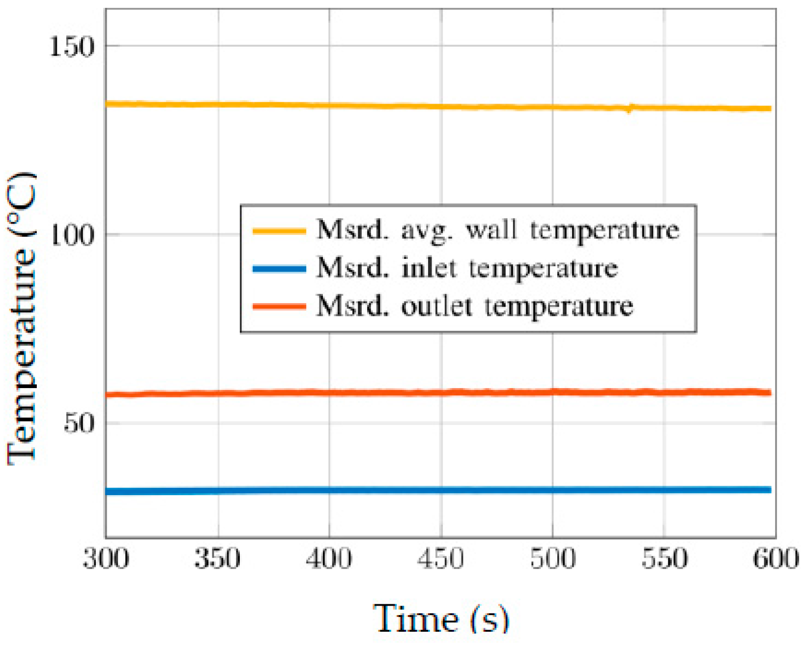
45] was to eliminate all but one thermal resistance between the cooling medium and the heat source, i.e., the conductors, to allow a large increase in the possible current density without exceeding the critical winding temperature. Due to innovative generative manufacturing methods, including cooling channels into the coils of electrical machines is now possible. Then, only the thermal resistance of the heat transfer between the single conductors of the coils and the cooling medium remains. The cooled surface area, and hence the heat dissipation capacity, are appreciably increased. Moreover, the coil geometry can be adapted to reduce losses due to current displacement and to further increase the heat dissipation. Lastly, the slot filling factor can be increased using hollow conductors due to the advantages of casted or 3-D-printed coils. A prototype of the coil displayed in
Figure 22 was casted with the help of a rapid-prototyped negative. The cast coil was supplied with DC current densities up to 100 A/mm
2. The used cooling medium was Galden HT135, a perfluoropolyether with a boiling point of 135 °C. The steady-state temperatures of the coil with a flow rate of 1.9 L/min and an inlet coolant temperature of 30 °C are shown in
Figure 23. The average coil temperature was measured as T
avg 135 °C.
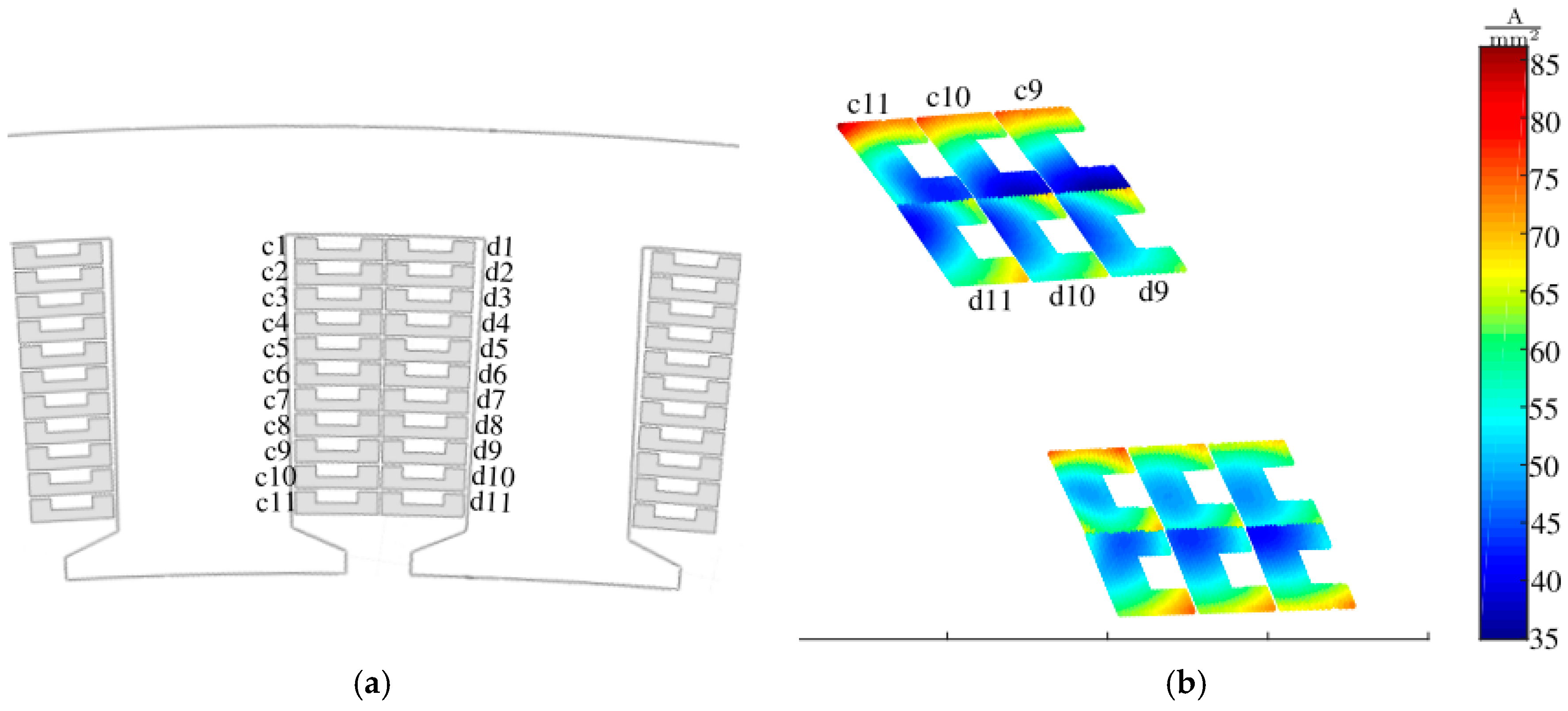
Figure 24 shows a schematic of a cast coil and the RMS current density distribution of two slots at 500 Hz. Due to the number of slots per phase and pole being 2/5, the current density distribution repeats itself every two slots. The average current density was 50.4 A/mm
2. The current displacement leads to a 15.4% higher loss. For comparison, the current displacement without cooling channels leads to a 22.6% increase in losses [
45].
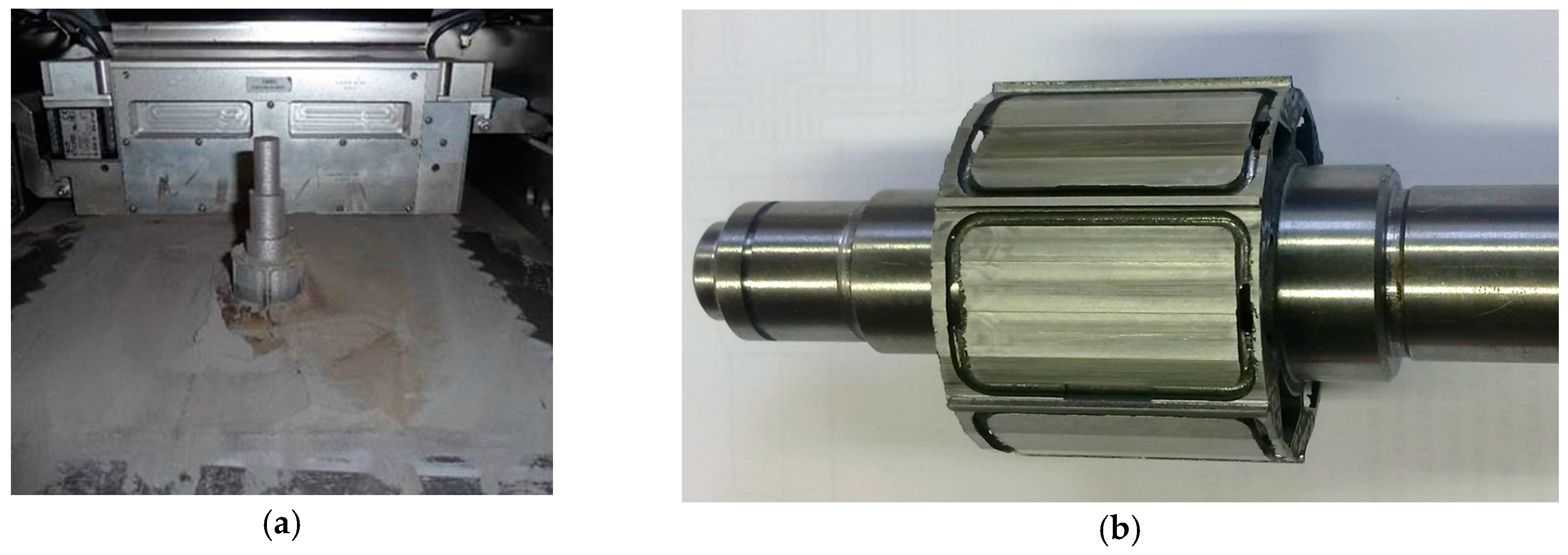
5.6. Metal Additive Manufacturing
Through the use of metal additive manufacturing technologies, building electrical machine parts layer per layer is possible. More specifically, fine metallic powder is fused by a high-power laser beam to create complex 3-D metallic structures (
Figure 25b), which has led to new design possibilities for electrical machine parts [
46].
Considering boundary conditions such as available space, layer thickness, or building time, every imaginable structure is producible [
47]. Currently, it is possible to process many different materials like titanium, aluminium, stainless steel and, particularly interesting for the field of electrical machines, soft magnetic materials, such as ferro-silicon or ferro-cobalt alloys [
46]. Because of this, the two-dimensional design limitation, due to conventionally laminated stator and rotor active parts, is negated. More specifically, this could be used to improve the cooling concept by placing cooling channels close to the origin of loss. Furthermore, implementing lightweight lattice structures beyond the flux paths to increase the machine’s power density and dynamics is possible. The latter improvement was successfully implemented in an additively manufactured rotor of a permanent magnet synchronous machine [
48].
Figure 25a, shows another additively manufactured rotor and shaft, which was introduced from Lammers et al. [
48], and was made of a soft magnetic ferro-silicon alloy, assembled and implemented into a conventionally manufactured stator, and successfully tested under usual operating conditions. Finally, handling of common three-dimensional machine features like skewing or machine end-effects becomes possible during the production process using metal additive manufacturing techniques [
49].
5.7. Insulation
Apart from the active components of an electrical machine, passive components, like the insulation, have to be considered for possible fatigue resulting from the environmental conditions during flight. The life span can be estimated from the amount of stress due to partial discharges. These stresses arise because of air inclusions in the insulation and are increasingly important for higher DC voltages under pulsed excitation. The voltage needed for a discharge can be calculated from Paschen’s law [
50]:
where
rI is the radius of an ion,
λ is the mean free path,
U is the voltage,
p is the gas pressure,
d is the distance,
kB is the Boltzmann constant,
T is the temperature, and
β is the second Townsend coefficient.
So, the breakdown voltage is a function of gas pressure and temperature. Both values change during the flight time of an aircraft. Pressure and temperature decrease when gaining altitude. When we formulate the dependence as:
by using an expression normed to standard atmospheric values and by assuming that the change of term
A is negligible, the temperature near the winding would be identical to the winding temperature. At cruising altitude, the air pressure is 19.1 kPa. For this case, a winding temperature of 120 °C was assumed. This would lower the breakdown voltage to approximately 2.3% of that at sea level at ambient temperature.
The demand for low weight and high efficiency has led to the use of higher DC-link voltages and increasing frequencies for electrical machines. With new developments in semiconductor materials, the switching frequency has been significantly increased, which steepens the switching edges to values above 50 kV/ns. Therefore, even at ground level, the common insulations may be insufficient. There is an immediate need for the development of better materials to operate electrical machines in low pressure and high temperature environments at high frequencies with high DC voltages under pulsed excitation. Changing environmental conditions during the flight, as well as increasing switching frequencies in combination with the demand for low weight, encourages the use of Teflon or Nomex-coated Kapton insulations instead of classical resin-based insulation materials.
6. Summary and Conclusions
A short overview of the requirements and demands of electrical machines for more-electric and all-electric aircraft, which will be significant in the coming years and decades, was presented. As an example, a currently available turbofan engine with a medium power demand was highlighted. Presently, different electric machine concepts need to be addressed and could prove to be feasible. Each was reviewed and evaluated in terms of their effectiveness and applicability. Eventually, the permanent magnet synchronous machine and the induction machine with squirrel-cage rotor were identified as the most promising electrical machine types for low-speed and high-speed operation, respectively. However, the properties and future usability of the machine concept as well as the components and materials need to be examined. This paper shows the possibilities of multi-phase, multi-layer windings in addition to common three-phase windings. Different conductor materials and superconducting materials were evaluated, as well as the flux exciting permanent magnets for synchronous machines, and the potential for up-to-date materials as the magnetic core. In addition to electromagnetic aspects, the mechanical evaluation, especially in the range of high circumferential speeds at high rotational speeds or with large bore diameters, was considered with different rotor armor materials, followed by a closer look at the challenges of the design of this banding. Thermal aspects cannot be disregarded. Hence, the sources of heat, with a closer look at the additional rotor losses, were shown, followed by the concept of an innovative cooling method for cast coils and arising opportunities from the currently researched additive manufacturing of electrical steel rotors with new design potentials. In considering all of the technical aspects and solutions, the focus can be shifted to the objective of building lightweight electrical machines.
The challenges for electrical machines emerging from the desire for more-electric or all-electric aircraft are many and demanding. This paper shows state-of-the-art concepts and materials. Furthermore, an assessment of the direction of future research and designs was discussed regarding current developments.

 ,
, 


