3.3.1. 21-Order Preliminary Simplified Model and Its Rationality Analysis
The transient process of a DFIG wind turbine system can be divided into an electromagnetic transient process and an electromechanical transient process according to the time scale. Electromagnetic transient simulation mainly studies the dynamic process of electromagnetic phenomena of voltage and current within one fundamental frequency cycle time (50 Hz, 20 ms). The time scale of an electromechanical transient process is generally 0.1–10 s.
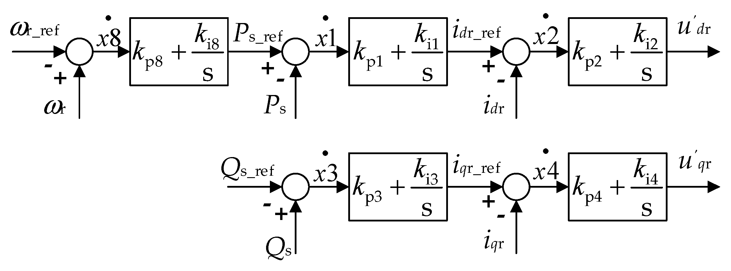
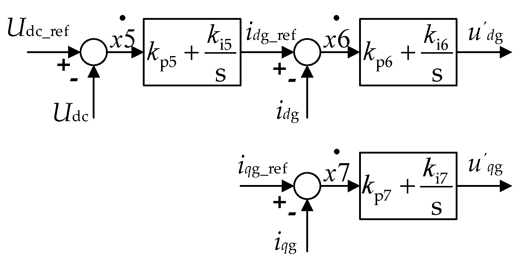
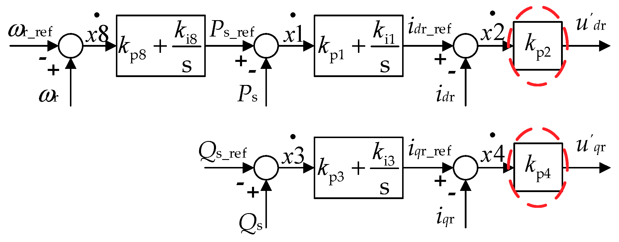
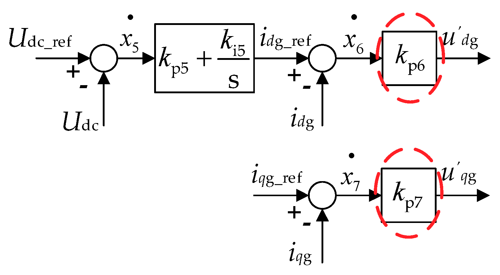
Firstly, in the electromagnetic transient process time scale, the integral link of the PI controller in the converter control system has not enough time to store much energy. Thus, it can be considered that the dynamics of control system is determined by the proportion link of the PI controller. While in the electromechanical transient process time scale, under the condition that no disturbance occurs in the internal variables of the inner loop of the control system, it can be considered that the inner loop controller of the control system can completely track the output of the outer loop of the control system, i.e., the input amplitude of the inner loop controller is so small that the accumulation of the integral link of the inner loop controller is neglectable. Therefore, the integral link of the inner loop controllers in
Figure 3 and
Figure 4 can be neglected, and the simplified control systems of the dual PWM converters are shown in
Figure 6 and
Figure 7.
Then, according to Equation (10), the additional items of the grid-side control system account for the dynamics of the stator voltage. The change of the stator voltage does not affect the voltage across the filter. The current of the filter is determined by the grid-side converter control system, and the
q-axis current of the grid-side filter is neglectable. Therefore, a 21-order DFIG wind turbine system model can be established. In order to verify the impact of the ignored variables on the overall trend of the system dynamics, the eigenvalues of the 21-order simplified model are calculated. The results are shown in
Table 2.
Comparing
Table 1 and
Table 2, it can be concluded that in the case of neglecting the integral link of the inner loop controller of the control system, as well as the
q-axis current dynamics of the grid-side filter, the eigenvalues of other modes in the system are little affected. Thus, the obtained 21-order simplified model is reasonable. Furthermore, the reduced-order model of a DFIG wind turbine system is respectively presented according to the time scales of the electromagnetic transient process and the electromechanical transient process, based on the 21-order simplified model.
3.3.2. Electromagnetic Transient Process Modeling
1. Analysis of the 15-order electromagnetic transient model
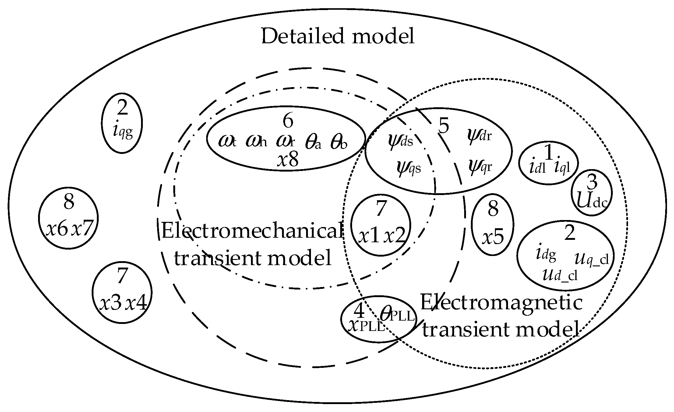
In the electromagnetic transient time scale, the work done by the imbalance of shaft torque to the generator rotor is little, while the inertia of the generator rotor is large. According to Equation (2), the generator speed is hardly changed. Therefore, the influence of the shaft on the DFIG wind turbine system can be ignored. I.e., assuming that the state variables of the shaft (
ωt,
ωh,
ωr,
θa,
θb, and
x8) are constants, the model can be further simplified to 15 orders. In this case, the eigenvalues of the reduced-order model are shown in
Table 3.
Comparing
Table 2 and
Table 3, it can be seen that the ignorance of the dynamic process of the state variables of the shaft module has little impact on the other modes of the system, and can well represent the electromagnetic transient process of the system.
2. Analysis of the 14-order electromagnetic transient model
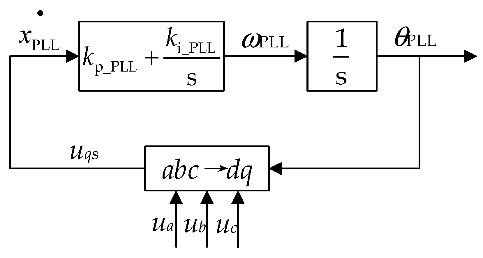
Further simplification can be applied by neglecting the variables that have little effect on the overall trend of the DFIG wind turbine system. For example, the ratio of the integral link gain to the proportional link gain of the PI controller of the PLL is small; the accumulation of the integral link is neglectable compared to the output of the proportional link in a short time. Therefore, the integral link of the controller of the PLL can be ignored, and the model can be further simplified to 14 orders. In this case, the eigenvalues of the reduced-order model are shown in
Table 4.
Comparing
Table 2 and
Table 4, it can be seen that only the characteristic values corresponding to the PLL have changed greatly because of the ignorance of the integral link. Since the relative phase angle
θPLL is output through the integral link, it may not affect the dynamics of the DFIG wind turbine system in a short time. Therefore, it is reasonable to ignore the integral link of the PLL controller.
3. Analysis of Other Reduced-Order Electromagnetic Transient Model of the DFIG Wind Turbine System
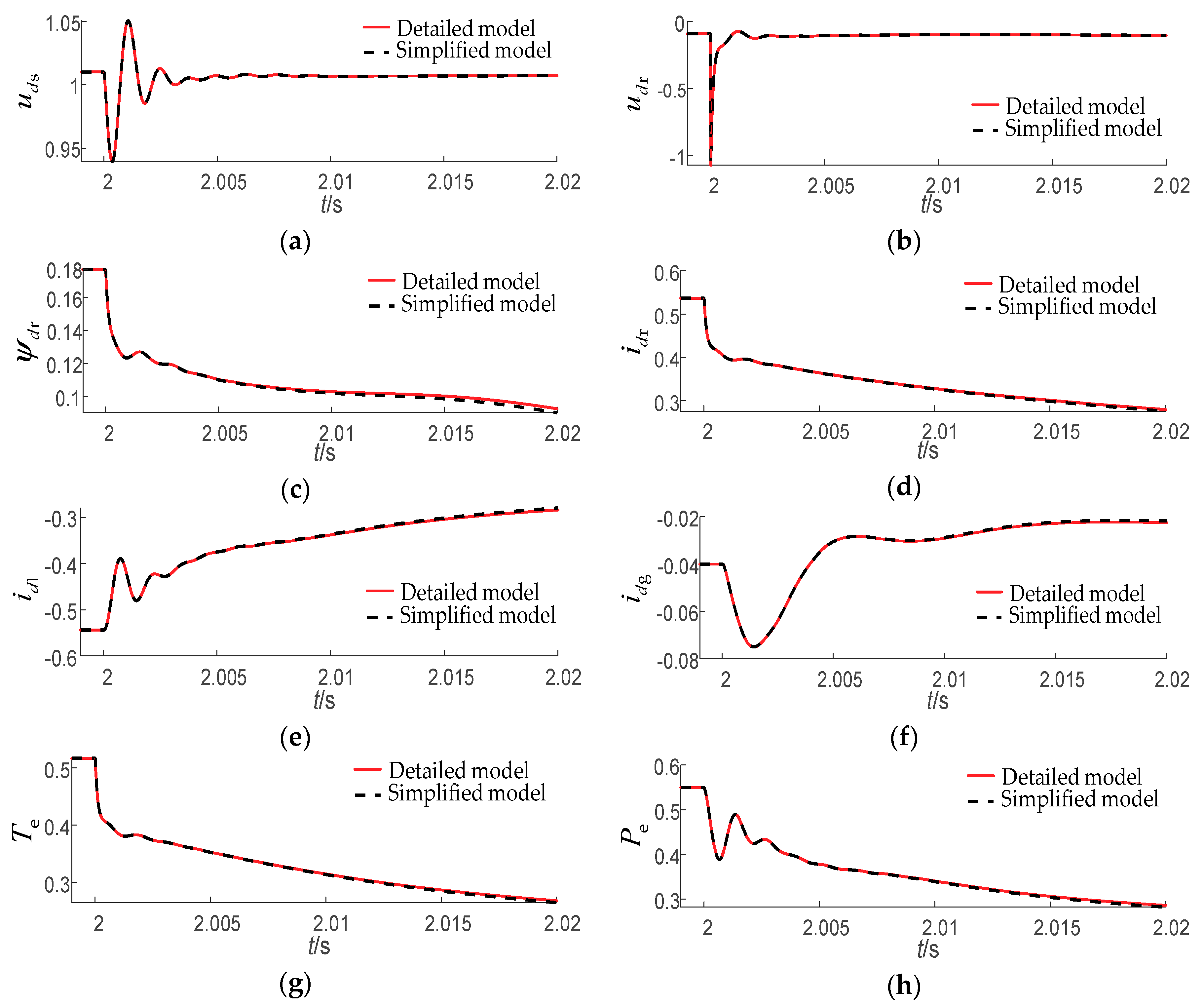
In the case of lower precision requirements, further simplification can be adopted on the basis of the abovementioned 14-order simplified model. Firstly, the integral link of the outer ring controller of the control system can be ignored, but this reduction is only effective in the smaller time scale (less than 10 ms). The reason is that since the ratio of the integral link gain to the proportional link gain in the outer ring controller is relatively large, i.e., the cumulative amount of the integral link has a great influence on the output of the proportional link, the time scale at which the simplified model fit the output curve of the detailed model will be reduced. Moreover, without the integral link, the control system cannot make an adjustment without a difference. In a larger time scale (from 10 ms to minutes), the simplified model cannot follow the output curve of the detailed model. In other words, ignoring the integral link of the PI controller of the outer loop of the control system is only suitable for studying the variation trend of each variable in an electromagnetic transient process time scale.
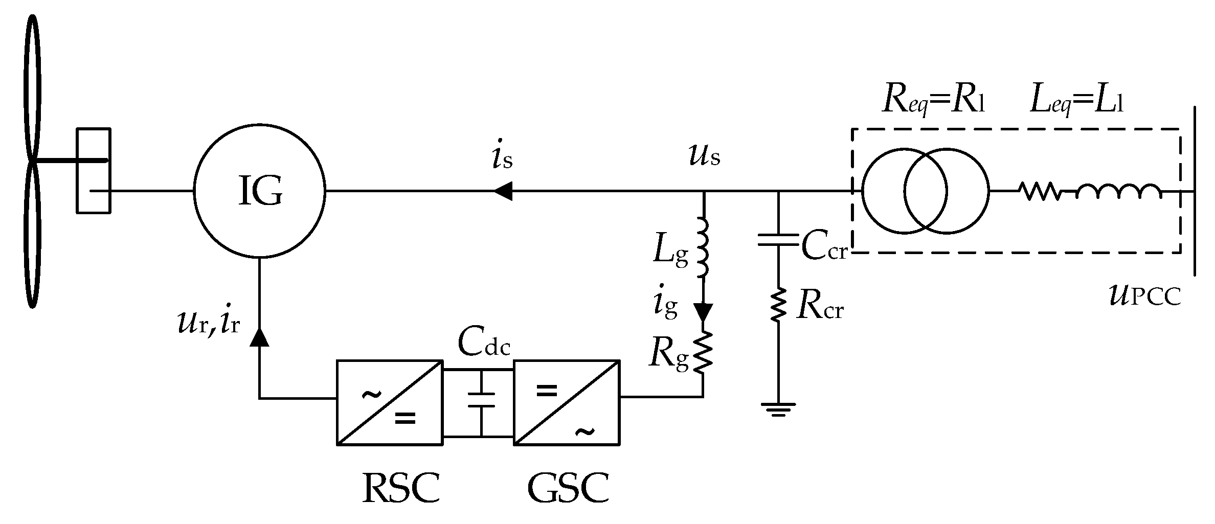
Secondly, if only the dynamic process of generator-side variables need analysis, the dynamic process of the grid-side filter and the DC voltage can be ignored. The reason is that according to the structure of the DFIG wind turbine system, the generator-side variables are not directly affected by the DC voltage and the grid-side filter. The output of the PLL can be assumed constant for further simplification if the dynamic process of the PLL is ignored. The validity analysis of the model simplifications is not repeated here.
3.3.3. Electromechanical Transient Process Modeling
1. Analysis of the six-order electromechanical transient model
According to
Table 1, the electrical variables and the control variables change faster than the mechanical variables. Ideally, the electrical variables and control variables mutate instantly in the electromechanical transient process. Thus, the simplified six-order electromechanical transient model is obtained; its eigenvalues are shown in
Table 5.
Comparing
Table 2 and
Table 5, it can be seen that the eigenvalues of the DFIG wind turbine system change greatly after ignoring the dynamic process of the electrical variables and control variables. This shows the dynamic process of the ignored variables has a great influence on the generator speed, and the six-order simplified model may cause a big error in simulation.
2. Analysis of the eight-order electromechanical transient model
According to Equation (4), the change of the stator flux linkage of the generator will cause the change of the rotor current in the electromechanical time scale. However, this is due to the effect of the rotor current inner loop in the rotor converter control system, as well as the response speed of the rotor flux linkage being far greater than that of the stator flux linkage (see
Table 1). The rotor flux linkage will quickly follow the change trend of the stator flux linkage, and the stator and rotor currents are almost changeless, i.e., the electromagnetic torque hardly changes. Therefore, it can be considered that the stator flux linkage does not affect the generator speed.
Moreover, the grid-side converter control system, which helps maintain the stability of the DC capacitance, is uncoupled with the rotor-side converter, and will not affect the stator and rotor currents. Therefore, the stator flux linkage, the grid-side state variables, and the inner loop controller of the control system have little influence on the generator electromagnetic torque. According to the natural frequency distribution in
Table 1, the intermediate variables of the outer loop (
x1,
x3) of the control system are added to the slow variables to better fit the dynamic curve of the shaft module, and then the eight-order electromechanical transient process model is obtained. The eigenvalues are shown in
Table 6.
Comparing
Table 2 and
Table 6, it can be seen that when the intermediate variables of the outer loop of the control system are taken into account, the error of the shaft dominant mode eigenvalues is reduced, and the overall dynamics of the shaft module will be better modulated. Meanwhile, the dominant mode eigenvalues of the outer loop intermediate variables change significantly. This is due to the ignorance of the dynamic process of the state variables corresponding to the outer loop control variables, and what corresponds to the power outer loop is the rotor flux linkage.
3. Analysis of the 10-order electromechanical transient model
The rotor flux linkage changes rapidly in the transient dynamics according to
Table 1, and thus can be ignored to accelerate the simulation speed. However, this may result in the collapse of the whole system. This is because when the dynamics of the rotor flux linkage is ignored, the rotor flux linkage will mutate if a large disturbance is introduced to the model, the accuracy of the control system will be reduced, and the errors will be magnified. Therefore, it is suggested that the rotor flux linkage dynamics should be considered in the electromechanical time scale, and thus, the 10-order electromechanical model is achieved. The eigenvalues are shown in
Table 7.
Comparing
Table 2,
Table 6, and
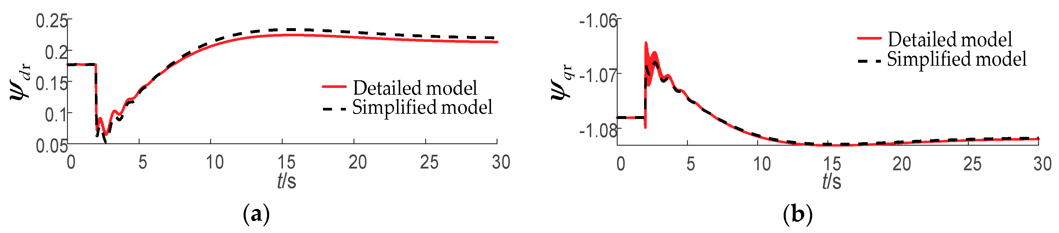
Table 7, it can be seen that after adding the rotor flux linkage dynamics, the errors of the eigenvalues of the outer loop of the control system and the shaft dominant mode are greatly improved, but it has a great influence on the eigenvalues corresponding to the rotor flux linkage dominant mode. Since the time constant of the rotor flux linkage is small and the dynamics of the rotor flux linkage decay fast, the influence of the rotor flux linkage on the shaft can be neglected. Therefore, the error of the eigenvalues corresponding to the rotor flux linkage dominant mode can be neglected.
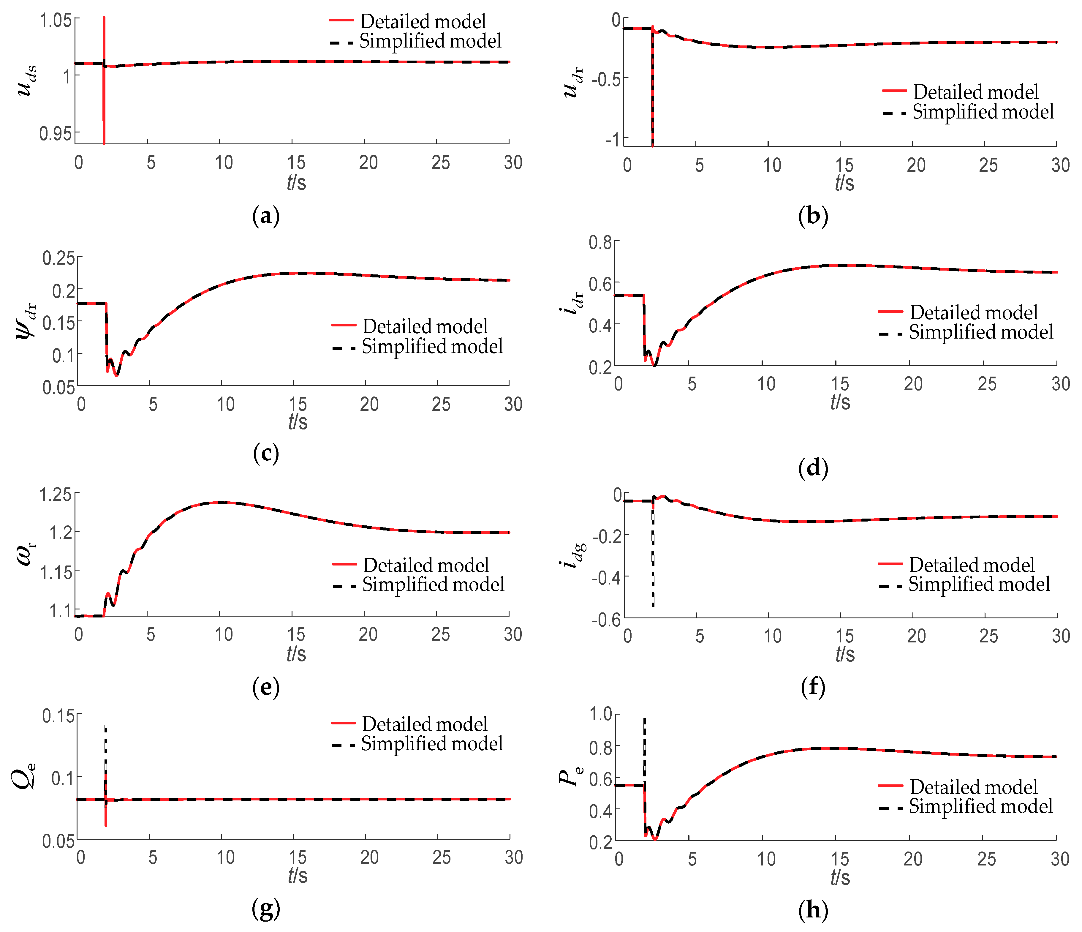
Since the dynamic process of the stator-side energy storage element is neglected and the change trend of the stator-side state variables are determined by the rotor flux linkage, the error of the rotor flux linkage is adopted to estimate the coincidence of the output characteristics of the 10-order simplified model and the detailed model. The dynamics of the rotor flux linkage for the detailed model and 10-order simplified model when the wind speed changes from 10 m/s to 11 m/s are shown as
Figure 8. From
Figure 8, it can be seen that the rotor flux balance point of the simplified system has been offset, which illustrates the analysis on
Table 7.
4. Analysis of the 12-order electromechanical transient model
The offset of the balance point of the 10-order simplified model is caused by the ignorance of the PLL in the electromechanical time scale. The dynamics of the PLL is directly related to the rotation speed of the rotating reference coordinate system. Ignoring the dynamics of the PLL will cause the missing of the deviation of the
d-axis and
q-axis voltage components at the point of common coupling (PCC) points, which makes the system balance point deviate. Therefore, taking into account the dynamics of the PLL in the electromechanical time scale, a 12-order electromechanical transient model is established, and the eigenvalues of the reduced-order model are shown in
Table 8.
Comparing
Table 2 and
Table 8, the time constant of the
d-axis flux linkage of the rotor doubles after taking into account the dynamics of the PLL in the electromechanical time scale. Meanwhile, the response speed of the
d-axis flux linkage of the rotor is still far greater than that of other state variables of the simplified model. Therefore, the influence caused by the change of the time constant of the
d-axis flux linkage of the rotor can be ignored.
5. Notification of the 12-order model and 10-order model
It should be noted that although the 12-order electromechanical transient model has higher precision than the 10-order model, its stability performance is worse under voltage sag conditions. The reason is that for the 12-order model, a large angular frequency error from the phase-lock loop output may occur because of the consideration of the dynamics of the phase-lock loop and the ignorance of the energy storage components in the stator side of the DFIG wind turbine system, resulting in the crash of the entire system.
Therefore, under voltage sag conditions, the 10-order electromechanical transient model should be adopted instead of the 12-order model. Under other conditions except voltage sag, the 12-order electromechanical transient model can be selected to improve the simulation accuracy.


