1. Introduction
Distributed generation technology, as a research direction of new energies development, refers to distributed generation devices (DGs) resettled directly into distributed networks or near loads, including the micro-turbine, photo-voltaic cell, wind turbine and fuel cell, etc. [
1,
2]. For the dispersion of DGs, comprehensive management and utilization are difficult (e.g., how to minimize power supply variations properly and maintain DGs power balance) [
3]. An autonomous power system consisting of various DGs, energy storage units, loads and its control system is called a microgrid and can effectively integrate DGs to maintain a stable power supply for loads [
4,
5,
6,
7]. Generally, microgrids that are small-scale low-voltage energy networks can be mainly used to ensure local generation and distribution in remote/isolated/underdeveloped communities [
8]. Besides, microgrids can partially address the challenges of safe network operation and efficient power control, brought on by huge numbers of DGs, in a decentralized way and further help large grids to reduce the control burden [
9].
Microgrids can work either autonomously (islanded mode) or be interconnected with large grids (grid-connected mode) [
10] through power electronic devices, and for the AC microgrid, the main device is the inverter [
11]. In normal operation, the microgrid is connected to the large grid, and DGs in the network can obey the large grid’s dispatching to operate without being in control. In case of a disturbance, the microgrid can disconnect from the large grid and enter islanded mode, at which point DGs need to work autonomously with appropriate control methods so as to maintain power stability. The islanded operation can bring more flexibility to the integration of DGs and provide a more reliable power supply, but islanded microgrids may become much weaker than traditional large grids for limited DGs capacities [
12]. Droop control, as a common control method of interfaced inverter in islanded mode, can spontaneously coordinate the dispatched powers of DGs by controlling their respective voltages without communication among DGs [
13,
14,
15]. It then implements the DGs’ plug-and-play function and peer-to-peer control. However, global running frequency deviates from rated value as loads change [
16]. The above frequency performance, attributed to the inherent droop feature, is hardly considered in the relevant literature. Besides, relative to bus voltage, deviation scales of DGs voltages are different for mismatched line impedance [
17,
18], so power-sharing inaccuracy remains to be settled [
19].
A consensus-based distributed frequency control method is proposed for frequency restoration in [
20]. Meanwhile the dependency on global communication links in frequency information exchange exists, so it is not absolutely decentralized. A finite-time control protocol for frequency restoration, based on feedback linearization, is proposed in order to synchronize the global frequency to nominal value with better disturbance rejection properties in [
21]. The frequency deviation is corrected by droop compensation in DG self-frequency restoration control without requiring a secondary controller [
22]. However, power coupling in P/f droop control, caused by resistive line impedance in low-voltage microgrids, seems not to be considered, so it is applied to high/medium-voltage microgrids. Generally, a method directly applied to low-voltage microgrids is P/U droop, but it is similarly limited to resistive line impedance (P/f droop is inductive line impedance).
In additional to frequency restoration, active power sharing inaccuracy caused by mismatched line impedance also remains to be settled. Although the two problems are settled together in some studies, they are mutually independent in P/U droop control [
23]. Enhanced virtual impedance is proposed to compensate mismatched line impedance for minimizing the power sharing error [
24,
25]. Virtual impedance is regarded as an effective tool for improving power sharing accuracy. Power information as a small disturbance signal is injected into the system to improve power sharing accuracy based on the power error before and after injecting the signal in [
26], but the stability declines. Paper [
27] uses low-bandwidth synchronization signals to activate the abovementioned sharing error reduction operation. It will lead to a decrease in DG voltages so as to reduce the impacts of line impedance. However, the application of simple communication may reduce stability.
Changeable reference, used in P/U droop control, is firstly proposed in this paper to realize frequency restoration and accurate active power sharing in low-voltage microgrids. The strategy is entirely decentralized without communication links between DGs. The innovative works of this paper are as follows.
Changeable frequency reference (CFR), suitable for frequency droop control, is proposed to restore the DG running frequency. For compensating the frequency deviation (e.g., frequency drop), the calculation of CFR is designed in an iterative way by adding real-time frequency deviation to the rated frequency. Thus, running frequency will stabilize at a rated value.
To obtain accurate active power sharing, changeable voltage amplitude reference (CVAR) in voltage droop control is proposed. The calculation of CVAR is also designed in an iterative way by adding the real-time line voltage drop to rated voltage, so that theoretical droop lines can be converted to actual droop lines corresponding to actual voltage.
Based on CVAR, the active droop coefficient is further improved so as to obtain a new droop line corresponding to actual DG operation. Even in the case of different DG voltages, active power sharing remains accurate. The same objective as with CVAR is realized, and voltage amplitude reference in the new droop line remains constant.
This paper considers the inverter impedance and designs its equivalent value as a negative line inductance. The elimination of line inductance contributes to strictly accurate active power sharing. Virtual impedance is used to realize the inverter impedance design.
Besides control precision, robustness problem is handled in inter-loop controllers by proposing a robust control method, based on the Lyapunov function that corresponds to DGs.
This paper is organized as follows.
Section 2 describes the principle of P/U droop control considering inverter impedance in low-voltage microgrids.
Section 3 describes the CFR-based improved frequency droop control.
Section 4 describes the CVAR-based voltage droop control and further improves the active droop coefficient.
Section 5 describes the related controller designs and robust control details.
Section 6 gives the simulation results.
Section 7 summarizes the paper and gives conclusions.
2. P/U Droop Control
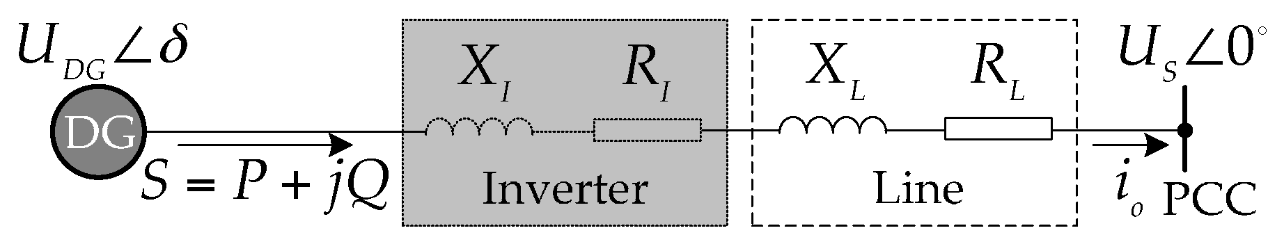
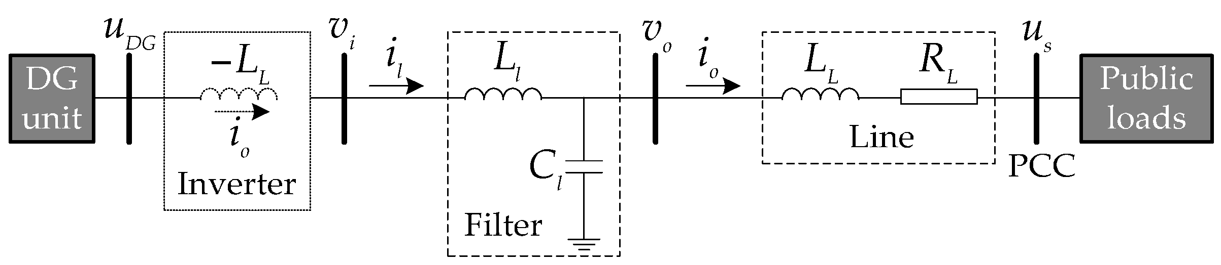
For a DG in the microgrid, the equivalent circuit of its grid-connected state is shown in
Figure 1, where
is DG voltage;
is DG powers output;
is bus voltage;
,
are line impedance;
is line current;
,
are inverter impedance whose values rely on the control demands when necessary (e.g., neutralize line inductance in this paper). The inverter impedance is not certainly a physical impedance but the equivalent impedance when the current flowing through inverter is equivalent to line current
. Based on the circuit in
Figure 1, the power outputs of DG are
Then, combine (1) with (2) and obtain the following equations
Impedance between DG and bus in low-voltage microgrids is mainly line resistance (
) [
28] without considering inverter impedance, where P/U droop control is applicable. Although line inductance is insignificant, the voltage drop in line inductance associated with the values of DG voltages affects power sharing. This paper considers the inverter impedance and designs its value for fully eliminating line inductance. Thus, power sharing is strictly improved and power coupling caused by line inductance is incidentally restrained [
29]. The virtual impedance method is used to design inverter impedance as given virtual impedance. For the above objective, design inverter impedance is negative line inductance:
. Hence, in the subsequent part, line inductance is unnecessary to be considered and “line impedance” is line resistance. Due to the small power angle
,
are reasonably assumed. Based on (3) and (4), we can derive as
Generally, power angle can be replaced by DG frequency
f. Hence, P/U droop control equations of DG are obtained as
where
m,
n are respectively reactive and active droop coefficients, given as
where
is frequency reference whose rated value is popularly 50 Hz;
is voltage amplitude reference whose rated value is equal to bus voltage;
are rated powers output;
is maximum running frequency;
is minimum voltage amplitude;
are maximal powers capacity. As seen in (7) and (8), DG running frequency is greatly affected by load power demands. The running frequency cannot stabilize at rated values when loads change. Hence, traditional P/U droop control is poorly adjusted in the stabilization performance of running frequency, and frequency restoration is necessary. In a microgrid with mismatched line impedance, DG (e.g., DG1, DG2) voltages are unequal (
) substituted into (8) and (10), and derive as
. Hence, active power sharing accuracy in traditional P/U droop control remains to be improved.
3. CFR-Based Improved Frequency Droop Control
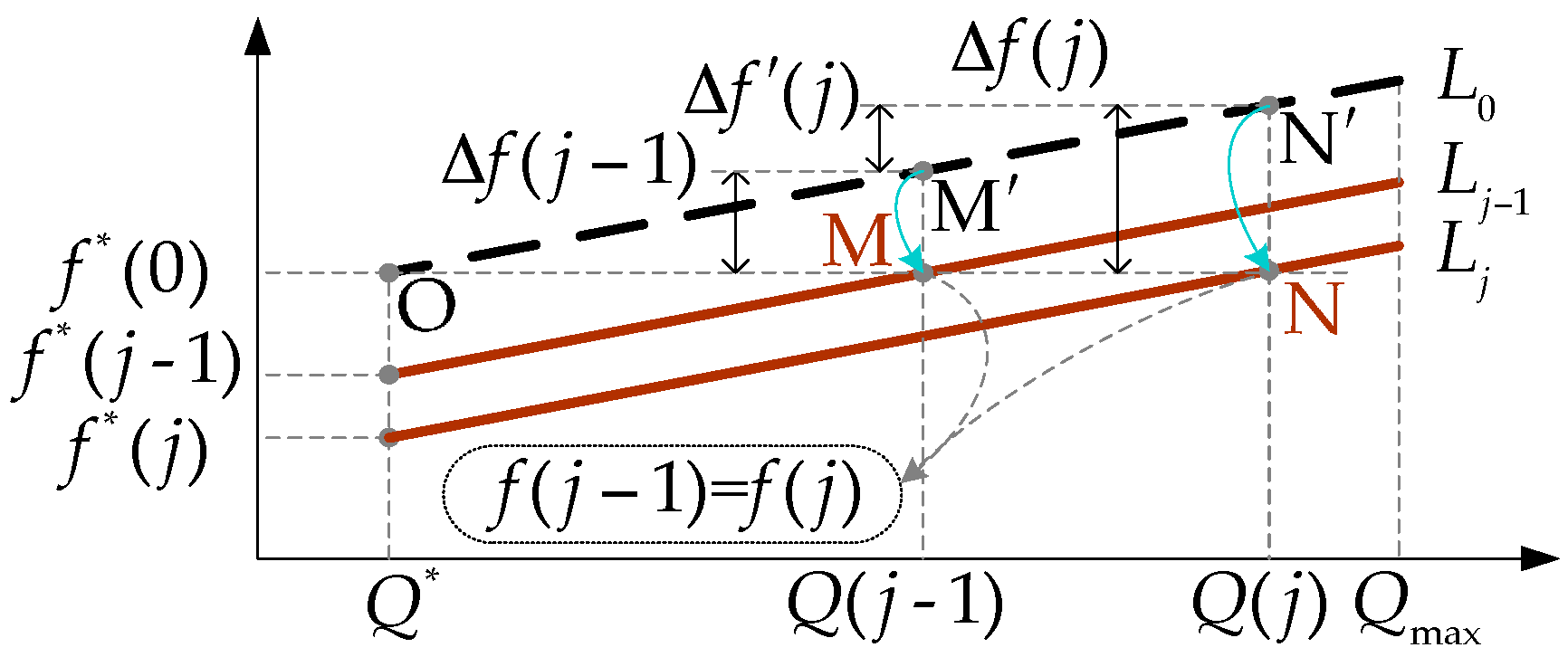
Traditional frequency droop feature of DG is presented as line
in
Figure 2, where
is the DG running frequency,
is the DG reactive power output,
is the running frequency deviation. Assume that DG operates at rated point O at initial state. When loads change at
t =
j, DG reactive power output changes to
and the frequency deviation of running point
relative to point O is
. Obviously, when loads change, the running frequency cannot stabilize at a rated value. So the frequency regulation in traditional droop control is a deviating regulation. To restore the running frequency to a rated value, CFR is proposed to compensate the frequency deviation (i.e., frequency reference increases/reduces as much as running frequency reduces/increases). The CFR value determination is related to the variation value of the DG reactive power output. That is, the value of CFR changes with loads. For any DG, detailed determination steps of CFR are as follows:
1. Determine the variation values of DG reactive power output.
Assume loads change at moments
t = 1, 2, ...,
j, ...
n (
j ≥ 2). Relative to reactive power output of DG at
t =
j − 1, the variation value of DG reactive power output at
t =
j is
When loads increase,
, otherwise,
. Define
(corresponding to DG assumed to run on non-load state at
t = 0 s, otherwise, it can be defined widely), the variation vector of DG reactive power output at (
n + 1) moments, set to
Q, is given as
2. Determine the compensation values of frequency reference.
Based on (7) and (11), the running frequency deviation at
t =
j is
Since
,
when
, otherwise,
when
. The running frequency is proportional to DG reactive power output. Set the frequency reference at
t =
j as:
According to (11)–(14), it is clear that when loads reduce/increase at
t =
j, the frequency reference increases/reduces as much as the running frequency deviation reduces/increases. The compensation vector of frequency references, set to
R, is given as
3. Determine the frequency references at (n + 1) moments.
Set the vector of frequency references to
F:
where
is also defined. Based on (14), we can obtain (17)
where
M is a constant matrix with (
n + 1)-dimensions and the rank is
n (rank (
M) =
n), given as
Frequency references at (
n + 1) moments as elements constitute the solution space
F of following nonhomogeneous linear equation:
where
E is an identity matrix with (
n + 1)-dimensions. Although the rank of coefficient matrix
E −
M is
n (rank (
E −
M) <
n + 1), the solution space of (19) is still definite for an initial condition
(i.e., special solution). The CFR calculation is similar to an iteration process of (14) with the initial value:
. Due to the uncertainty of load changes, it is preferential to obtain the frequency reference at the current running moment. Even in case of continuous or frequent load variations, the proposed CFR calculation at all load change moments is feasible, otherwise, use (14) directly to calculate the frequency reference at the current running moment.
As shown in
Figure 2, lines
are the CFR-based improved frequency droop lines at
t =
j − 1,
j. In addition, the corresponding running points are M, N changed from points
. Relative to point O, frequency references reduce as much as original frequency increases (
). When loads change at
t =
j, DG reactive power output is changed from
Q (
j − 1) to
Q(
j) and frequency reference is changed from
to
according to (14). If frequency reference remains constant at
t =
j, the frequency deviation
will exist. Line
is necessary to serve as frequency droop line at
t =
j. So frequency references should be changeable with load variations to stabilize running frequency. Thus, running frequency hardly changes when loads change at
t =
j (
). Hence, within the allowable range of DG reactive power output, running frequency can be maintained at 50 Hz no matter how loads change.
4. CVAR-Based Improved Voltage Droop Control
4.1. CVAR Determination
Active power sharing in accordance with DG power capacity largely depends on whether DG voltages are consistent. However, there are unequal line voltage drops between actual DG voltages and bus voltage associated with mismatched line impedance, so that values of actual voltages are slightly larger than theoretical values. Theoretical voltage droop lines so not satisfy actual voltages. If we still use the theoretical voltage droop lines to control DGs, active power sharing will be inaccurate for different actual voltages caused by unequal line voltage drops. Hence, line voltage drops are considered to improve voltage droop features by proposing CVAR when loads change. The principle of CVAR is adding line voltage drop to rated voltage amplitude reference, so that theoretical droop lines can be converted to actual droop lines corresponding to actual voltages. Only when droop lines are suitable for actual voltages will active power sharing be accurate in the case of discrepant DG voltages. This paper considers the inverter impedance and designs it as negative line inductance, so following “line voltage drop” refers to voltage drop in line resistance. For any DG in a microgrid, the detailed determination steps of CVAR are as follows:
1. Determine the variation values of “line voltage drop”.
Assume loads also change at moments
t = 1, 2, ...,
j, ...
n (
). Relative to the “line voltage drop” at
t =
j − 1, the variation value of “line voltage drop” at
t =
j is
For line current increases as loads increase,
, otherwise,
. Define
(corresponding to DG assumed to run on non-load state at
t = 0 s, otherwise, it can be defined widely), the variation vector of “line voltage drop” at (
n + 1) moments, set to
O, is given as
2. Determine the voltage amplitude references at (n + 1) moments.
Set the DG voltage amplitude reference at
t =
j to
According to (20) and (22), it is clear that when loads reduce/increase at
t =
j, voltage amplitude reference reduces/increases as much as “line voltage drop” reduces/increases. The vector of voltage amplitude references at (
n + 1) moments, set to
U, is given as
where
(i.e., voltage amplitude reference at initial time or no-load running state) is generally the bus voltage (
). Based on (22), there is
where
M is shown in (18). Voltage amplitude references at (
n + 1) moments as elements constitute the solution space
U of following nonhomogeneous linear equation:
The coefficient matrix in (25) is the same with (19), so the solution space of (25) is also definite for an initial condition , i.e., special solution.
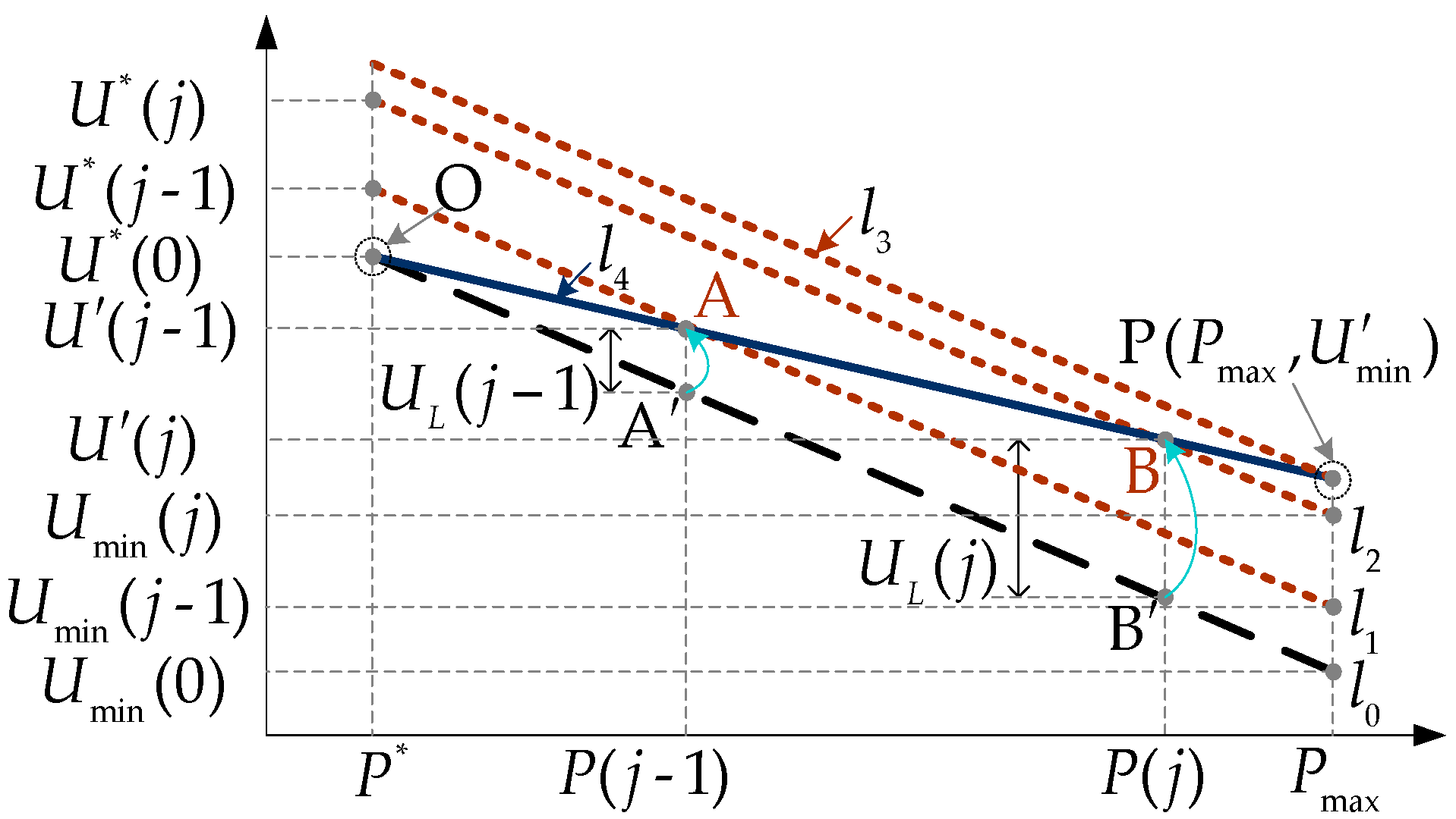
Voltage droop features are shown in
Figure 3, where line
is the traditional/theoretical droop line at
t = 0; lines
l1,
l2 are the CVAR-based improved droop lines at
t =
j − 1,
j; line
l3 is also the improved droop line corresponding to maximum active power running point P;
is the DG actual voltage;
is the DG active power output;
is the ‘line voltage drop’. Because the “line voltage drop” exists at
t =
j − 1,
j, running points are changed from points
to points
dissatisfied with line
. If we still use line
to control actual voltage, active power output will deviate from theoretical value. Considering impact of “line voltage drop”, design voltage amplitude references at
t =
j − 1,
j, so that actual droop lines
conforming to actual voltages are obtained. If we use lines
to control actual voltages, active power outputs will return to the exact value.
4.2. CVAR-Based Active Droop Coefficient Improvement
When loads change at
t =
j, the actual running point will change from A to B and the corresponding droop line will also become line
. So line
is only applied to actual running point A at
t =
j − 1 and cannot cover all the DG running points at (
n + 1) moments (e.g., point B). When loads change, all the actual DG running points do not synchronously meet the identical improved droop line with the same voltage amplitude reference. There are (
n + 1) droop lines that respectively correspond to (
n + 1) running states at (
n + 1) moments. Namely, DG at different running states has different droop lines. To further improve CVAR-based droop control, a line applicable to all the actual DG running points is derived as line
in
Figure 3, which is proved in subsequent part. The equation is deduced as follows:
1. Determine the coordinate of point P () when DG dispatches maximum active power.
The ‘line impedance’ in proposed low-voltage microgrid using virtual negative inductance is line resistance. Based on (6), when DG dispatches maximum active power, ‘line voltage drop’ is
Hence, the y-axis of point
P is
Thus, the coordinate of point P is ().
2. Determine the equation of line .
The coordinate of DG no-load running point O is (
). Based on coordinates of two points in line
and (10), the line equation is deduced as
where
is DG actual voltage,
is the improved active droop coefficient :
Based on (6), the ‘line voltage drop’ at a random moment (e.g.,
t =
j) is
Based on (8), DG actual voltage at
t =
j is
From (28) to (31), it is deduced that the coordinates of actual DG running points as loads change synchronously satisfy the equation of line , so it is summarized as the actual voltage droop line. It is worth noting that voltage amplitude reference in actual voltage droop line just remains at the rated value (i.e., bus voltage).
4.3. Improved Active Power Sharing
For a microgrid with multiple parallel DGs (e.g., DG1, DG2), difference in DGs actual voltages based on (28) is
According to (6), DGs actual voltages can be expressed as
We can substitute (10) and (33) into (32) and deduce as
Hence, in case of discrepant DGs actual voltages, accurate active power sharing of DGs controlled by line is proved.
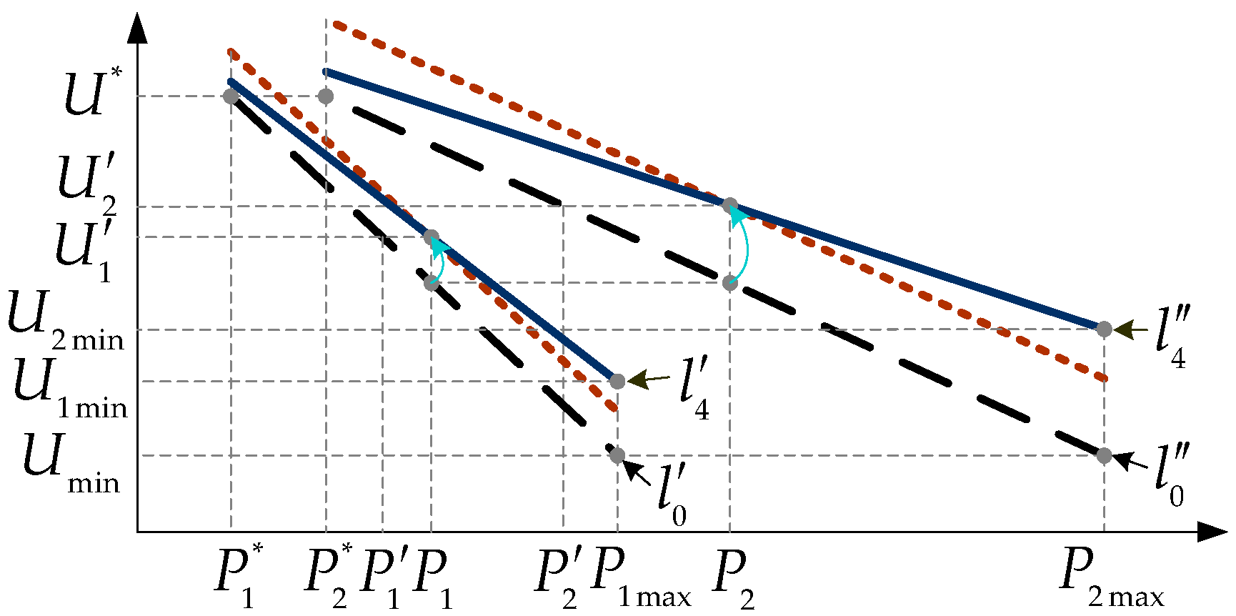
Performance of improved active power sharing in accordance with DG active power capacity is shown in
Figure 4, where
are the traditional droop lines of DG1, DG2. When lines
are used for active power sharing and “line voltage drop” isn’t considered, the active power sharing (
) is accurate for equal voltages. However, the significant “line voltage drop” has to be considered, so DG actual voltages are discrepant (
). If we still use lines
to control DGs, actual active power sharing (
) will deviate from accurate value (
). Lines
are the CVAR-based improved droop lines of DG1, DG2. If they are used for active power sharing, the improvement of active droop coefficient restores DG active power output back to accurate value without changing actual DG voltages. So it is unnecessary to consider whether DG actual voltages are consistent, and meanwhile, performance of active power sharing is relatively fine.
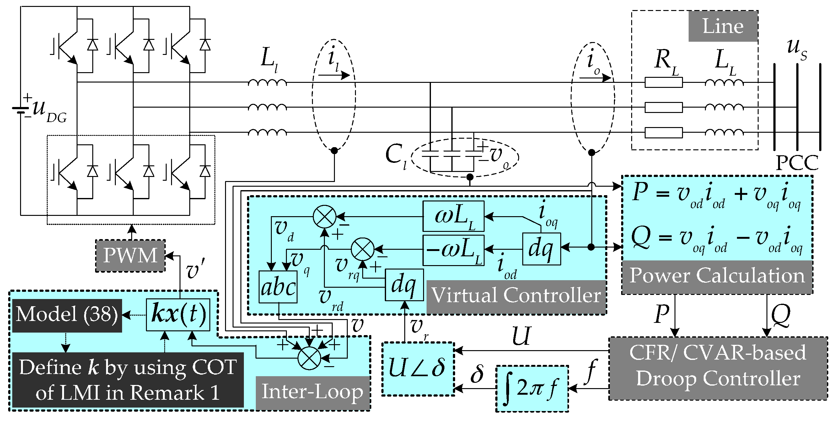
5. Control System of Improved Droop-Controlled Inverter
The control system of an improved droop-controlled inverter in a low-voltage microgrid, realized for frequency restoration and accurate active power sharing, is shown in
Figure 5, where
is filter inductance,
is filter capacitor. Input capacitor voltage
and line current
assess the power calculation mode and obtain DG active/reactive power outputs. Then, the droop controller realizes the CFR/CVAR-based improved P/U droop control and sends “order voltage”
to a virtual controller. Generally, in a virtual controller, one must subtract the virtual voltage drop from the “order voltage” to realize virtual impedance [
30,
31] and then obtain a new “order voltage”
. In the inter-loop controller, robust control is used to realize that capacitor voltage tracks a new “order voltage” with minimum robustness problem in case of load variations. Pulse width modulation (PWM) mode modulates the waveform of the inverter voltage.
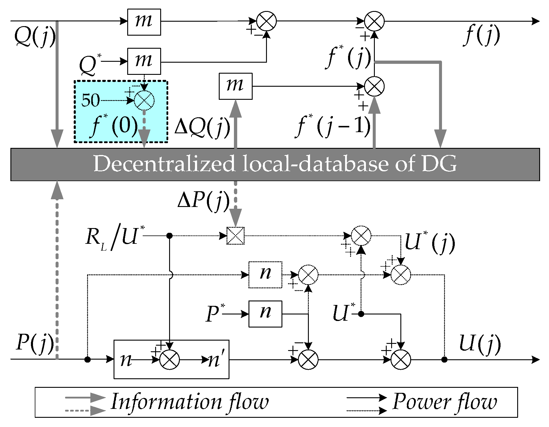
5.1. CFR/CVAR-Based Droop Controller Design
Figure 6 describes the detailed design of a droop controller. Based on (19) and (25), the calculation systems of CFR and CVAR are established, and CVAR calculation is replaced by a control pattern designed as (28). The iteration calculation of references relies on the established database, which is used to extract and store related physical information such as DG active/reactive power, and frequency references. The DG active/reactive powers outputted from power calculation mode are immediately stored in the database after per loads change. Then, the database extracts previously stored information (DG powers output before loads change) and obtains variation values of DG powers. The previous references necessary for reference calculation also need to be extracted. Then, new references can be obtained to contribute to an improved droop control, and meanwhile, they will be stored to the database in time for preparing the next reference calculation in advance. The application of the control pattern as (28) instead of CVAR dispenses with the storage and reading of related information in CVAR calculation. Thus, the quantity of uploaded and downloaded information reduces.
The proposed control strategy is realized within all the individual DGs, so cooperation of DGs is unnecessary. The decentralized local database of DGs means communication links among DGs are unnecessary. Each database only stores and extracts physical information of the corresponding DG to which it belongs. Generally, active power sharing, scilicet, is the coordination among active DG power outputs. However, in this paper, the accuracy improvement of active power sharing depends on the independent design of CVAR/improved active droop coefficients, only considering respective line impedance. Each DG is similar to an “isolation room” for their self-governed operations can share the load demands based on their respective capacities. Due to the unnecessary communication links and little information in the local database, delay time in data transmission is almost nonexistent.
5.2. Virtual Controller Design
A virtual controller, used to realize virtual impedance, plays a decisive role in the evaluation of inverter impedance. As shown in
Figure 5, line current is fed back to calculate the virtual voltage drop
. To emulate an actual impeder, one must subtract virtual voltage drop from “order voltage”. Meanwhile, a new “order voltage” for the inter-loop controller must be generated. Differentiation of line current in calculation of virtual voltage drop (
) can easily result in high-frequency noise amplification and even destabilize the voltage control stability, especially during a transient [
25]. An effective method to avoid the above problem is approximating
as
, which is realized in the polar form through direct complex number manipulations in the dq frame. Hence, virtual voltage drop in the dq frame is given as
Then, a new “order voltage” for inter-loop controller is obtained as
5.3. Inter-Loop Controller Design
Because CFR/CVAR is associated with load variations, their applications will inevitably affect system robustness in case of load variations. Besides the control precision in the proposed droop control method, the other pivotal problem is how to choose an appropriate method to handle the robustness stabilization problem in the inter-loop controller. A robust control method based on the Lyapunov function is proposed corresponding to actual DGs. The following section will describe the stabilization design method.
Based on the structure diagram of the DG unit given in
Figure 7, the mathematical model of the DG unit applying Kirchhoff laws is formulated as follows
Considering uncertainties of loads change and line/filter parameters, the dynamic model of the DG unit as (37) might be expanded into the following form
where
is state matrix of the DG unit;
is control input;
is control output;
is assumed to be a disturbance signal preferably set to zero;
,
,
and
are coefficient matrices with appropriate dimensions.
Then, the inter-loop controller of the DG unit in
Figure 5 is designed as state feedback control
where
is the control gain of the inter-loop controller.
Based on (38) and (40), the dynamical model of the DG unit is rearranged in the following from
where
.
We define the Lyapunov function for the control system as
where
is the symmetric positive definite weighting matrix of DG.
Considering the initial condition, H∞ performance related to the controlled output is given as
where
is a prescribed attenuation level. Physical meaning of (43) is minimizing impact of
on output
, scilicet, impact of disturbance (loads variation) on tracking error in the inter-loop controller is attenuated below a desired level.
Theorem 1. The controlled unit (41) can be H∞ robust stabilization by the inter-loop controller (40), only if is the common solution of the following symmetric matrix inequality.
where is an identity matrix.
Proof. The derivative of
along the trajectory of system (42) satisfies
It is easy to obtain as
☐
Based on the above result, if matrix inequality (44) is satisfied, the system of (41) is H∞ robust stabilization by inter-loop controller (40). The inequality (44) is linear matrix inequality (LMI).
Remark 1. To obtain better robust performance, H∞ robust stabilization control can be treated as the following minimization problem as (47), so that the H∞ performance in (43) can be reduced as small as possible The minimization problem in (47) can be transformed into a LMI convex optimization problem. By using convex optimization techniques (COT) of LMI, inter-loop controller control gain as well as minimization H∞ robust performance of proposed droop control system can be obtained.
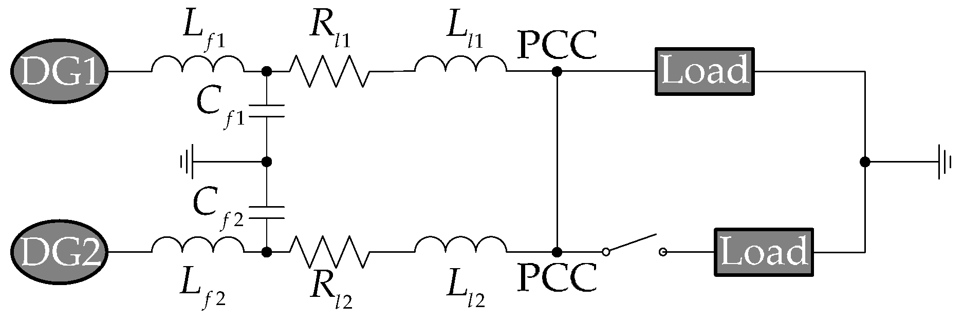
6. Simulation Results
The simulation model shown in
Figure 8 has been established in a platform RT-LAB (Opal-RT Technologies Inc, Montreal, QC, Canada). The model is summarized as an islanded microgrid with two parallel DGs and several public loads. Simulation parameters are shown in
Table 1. The improved active droop coefficients are selected by (29). Microgrid operates at no-load state at
t = 0 s. DGs share the powers in a ratio of 1:1. To analyze the performance of reactive power/frequency and active power/DG voltage in case of load variation, simulation results are divided into three phases: increase loads (3000 W, 1000 Var) at
t = 0 s; increase 100% of loads at
t = 1.0 s; reduce 50% of loads at
t = 2.0 s.
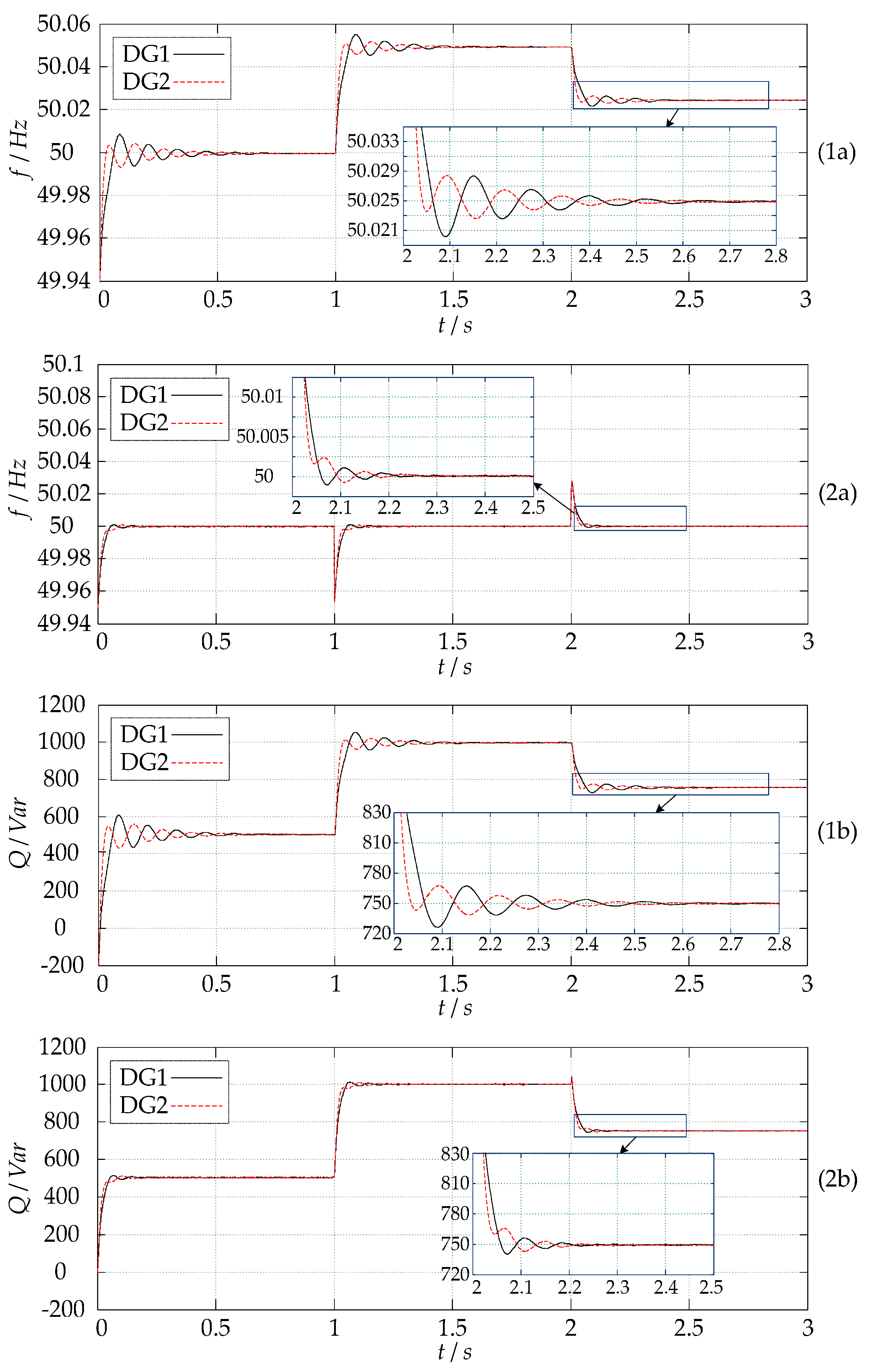
6.1. Results of Reactive Power/Frequency
Figure 9 shows the performance of reactive power and frequency in case of load variation. Two methods are verified: method 1 (traditional method) uses the constant frequency reference; method 2 (proposed method) uses CFR. As seen in (1b), DG1 and DG2 dispatch rated reactive power (500 Var) during
t = 0 s to
t = 1.0 s when putting given loads into use. Corresponding to (1a), running frequencies of DG1 and DG2 maintain at 50 Hz during
t = 0 s to
t = 1.0 s. However, once total loads change after
t = 1.0 s, running frequency stabilizing at rated value can be then lost. In detail, because frequency is proportional to DG reactive power output in (7), the frequency in method 1 (traditional method) can increase as loads increase at
t = 1.0 s and reduce as loads reduce at
t = 2.0 s. Corresponding to (1b), DGs reactive power sharing is, however, accurate (1:1) due to the frequency synchronization in (1a). However, one remarkable thing is that the overshoot time, about 0.7 s, is relatively long.
Similarly, in (2a), running frequency in method 2 (proposed method) has been stabilized at rated value after t = 1.0 s. It attributes to the contribution of CFR, whose compensation can restore running frequency to rated value (50 Hz). A sudden change of frequency reference can result in the drop/rise in running frequency at t = 1.0 s/2.0 s in (2a). Specifically, based on (14) or (19), frequency references of DG1 and DG2 change from 50 Hz to 49.95 Hz at t = 1.0 s and change from 49.95 Hz to 50.025 Hz at t = 2.0 s. Relative to (1a), although the values of running frequency change, frequency synchronization still remains constant. Meanwhile, the same applies to DG reactive power sharing accuracy (1:1). The overshoot time as about 0.25 s becomes significantly shorter. Due to certain different system parameters of DG1 and DG2, including unbalanced line impedance, their quick responses to load changes may also be different. Thus, in (1a) and (2a), it may result in different frequencies of DG1 and DG2 in the overshoot stage. The above analysis indicates that CFR can be used to restore running frequency without influencing DG reactive power output. In addition, robust control, used in the proposed method, can minimize the robustness problem of DG frequency and reactive power in the case of load changes or disturbances.
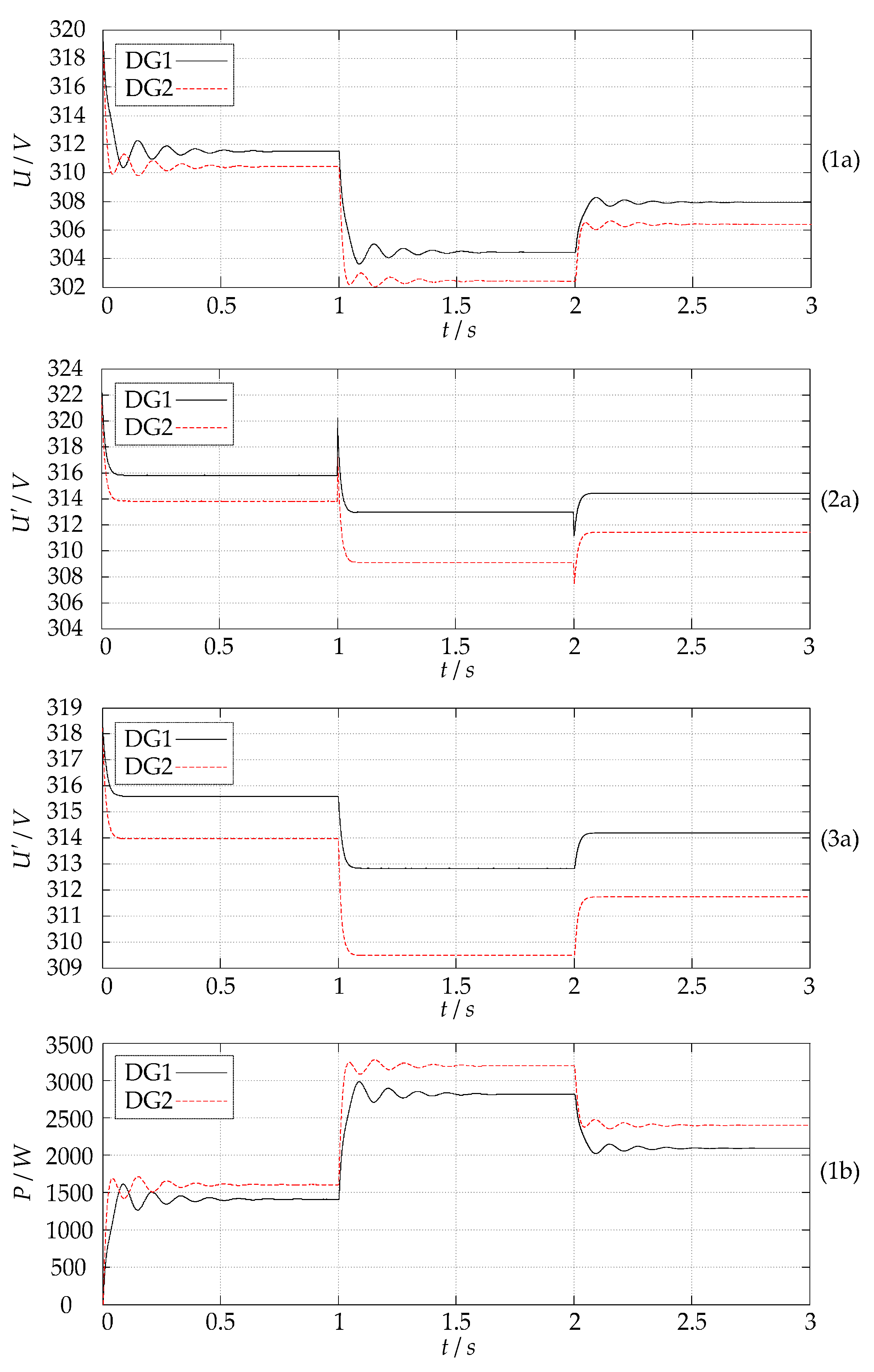
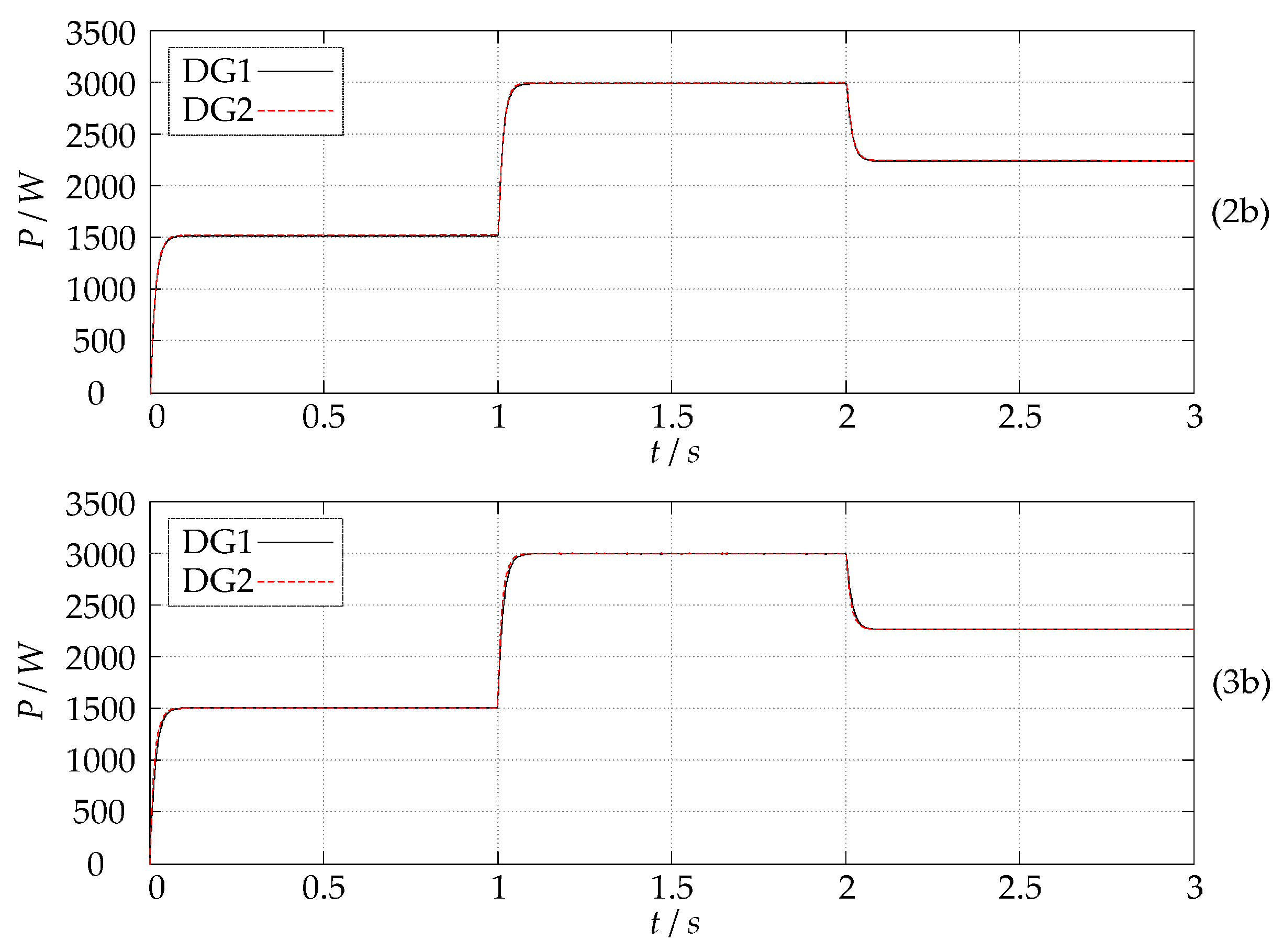
6.2. Results of Active Power/DG Voltage
Figure 10 shows the DG voltage deviations and active power sharing accuracy. Three methods are verified: method 1 (traditional method) uses constant voltage amplitude reference; method 2 (proposed method) uses CVAR; method 3 (proposed method) uses an improved active droop coefficient. As shown in
Figure 10, because DG voltages are inversely proportional to DG active power outputs in (8), DG voltages will reduce/increase/reduce as loads increase/reduce/increase at
t = 0 s/
t = 1.0 s/
t = 2.0 s. In method 1 (traditional method), as total loads change after
t = 0 s, deviation in DG voltages in (1a) caused by mismatched line impedances results in active power sharing inaccuracy in (1b). In detail, when loads increase/reduce, the voltage drop in line impedance can further increase/reduce, which can result in increased/reduced DG voltage deviation in (1a) and further increase/reduce active power sharing inaccuracy in (1b). Besides, the overshoot time as about 0.6s is also relatively long in method 1 (traditional method).
In method 2 (proposed method) using CVAR and method 3 (proposed method) using improved active droop coefficient, because voltage drop in line impedance is added into traditional voltage amplitude reference, the DG voltages can increase in (2a) and (3a) relative to (1a). Although DG voltage deviation still exists in (2a) and (3a), the active power sharing in (2b) and (3b) are accurate by using actual voltage droop line to control DGs. Small differences in (2a) and (3a) are the obvious voltage droops/rises in (2a) for sudden reference changes. In addition, voltages in (3a) are relatively stable. The voltage droops/rises in (2a) hardly have an impact on active power sharing for the almost none droop/rise time, so sharing performances in (2b) and (3b) are almost consistent. The same applies to frequency; the overshoot time is almost nonexistent in the proposed method, attributed to robustness minimized by the proposed robustness control. Therefore, either method 2 or method 3 improves the active power sharing accuracy in case of loads variation. The above analysis indicates that CVAR or an improved active droop coefficient can be used to improve active power sharing accuracy. Besides, robust control can also minimize robustness problem of DG voltages and active power in case of load changes or disturbances.
7. Conclusions
An improved P/U droop control strategy based on changeable reference is proposed for restoring frequency and improving active power sharing accuracy. In the case of load changes, DG running frequency can stabilize at the rated value (50 Hz) by changing frequency reference to compensate for frequency deviation while hardly influencing DG reactive power output. Thus, frequency restoration is realized by using CFR in the proposed method. Besides, to eliminate the influences of line inductance on active power sharing accuracy and power coupling, we use a virtual impedance method to design the inverter impedance as negative line inductance to neutralize line inductance. Then, we consider voltage drop in line impedance and give CVAR. Thus, actual droop lines corresponding to actual DG voltages can be obtained and will be used to control DGs so as to improve active power sharing accuracy. CVAR is further simplified as improving active droop coefficient. By using improved active droop coefficient to control DGs, active power sharing is still accurate and the performance of DG voltage stability will be better. Besides the control precision, the robust performance in the case of load changes or disturbances is also discussed. By proposing and using a robust control method based on the Lyapunov function in the inter-loop controller, robustness problems of frequency/voltage/powers are minimized. The simulation results coincide with the above theoretical results (i.e., the proposed method really contributes to frequency restoration and power accuracy improvement, with good robustness).


