1. Introduction
With the increasing penetration of renewable energy into the grid, power quality and stability issues become more and more important. In distributed power generation system (DPGS), a grid-connected converter is usually used as the interface between the renewable energy and grid, which plays an important role in injecting high quality power into the grid [
1,
2,
3]. For the grid-connected converter, an LCL filter is usually preferred to attenuate the switching frequency harmonics due to its having a higher harmonic attenuating ability than an L filter [
4,
5]. For the three-phase LCL-type grid-connected converter, the most widely used current control method is the proportional-integral (PI) control in
dq frame [
1,
6].
Many areas for improving the control performance of the LCL-type grid-connected converter have been discussed. To suppress the resonance peak of the LCL filter and avoid the attendant power loss of passive damping, some active damping control algorithms have been discussed [
7,
8]. Among various active damping solutions, capacitor current feedback active damping is widely used for its ease of implementation [
4,
9]. The suppression of the grid current harmonics caused by distorted grid voltage is discussed in [
10,
11,
12], and control delay compensation is discussed in [
13,
14]. However, there is very little literature on its start-up performance, which is an indispensable part of grid-connected converter current control.
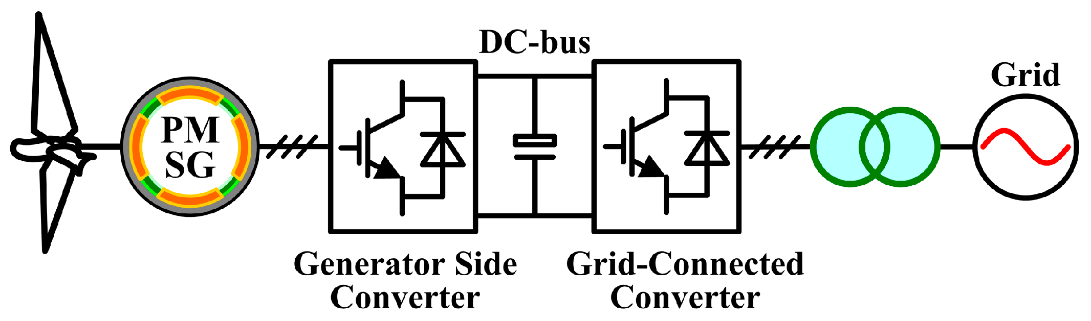
When the DPGS starts, for example, the direct-drive wind power generation system (DDWPGS), as shown in
Figure 1, before the grid-connected converter begins to work, the DC-bus capacitor will be pre-charged through the antiparallel diodes of the switches, until the DC-bus voltage is slightly below the peak value of grid line voltage, but far below the DC-bus voltage reference. Then, the grid-connected converter starts in rectifier mode and continues to pre-charge the DC-bus capacitor, until the DC-bus voltage reaches its reference. Then, the generator side converter starts, with grid-connected converter running in the inverter mode. However, when running in rectifier mode, the grid-connected converter would cause serious inrush current at the start time if no effective control method is employed [
15]. Such inrush current may result in triggering overcurrent protection, and even damage the switching devices.
To suppress the start-up inrush current, for a grid-connected converter or pulse width modulation (PWM) rectifier, some control strategies have been studied. Reference [
16] introduces constant terms into the current control loops to smooth the start-up behavior. Reference [
17] proposes a method to pre-charge the DC-bus voltage until it reaches a certain level, at which point the conventional control strategy is adopted. However, these pre-charge methods are complicated. In [
18], the current of the DC-bus capacitor is used as the reactive current reference during start-up. However, the inrush current is not particularly dependent on current reference when the converter starts, so such methods of current reference change cannot fundamentally suppress inrush current [
15]. Reference [
19] injects a reverse DC component current into the main circuit to mitigate the start-up inrush current. However, according to the simulation results in [
19], this method can only accelerate attenuation of the inrush current, but cannot fundamentally suppress the generation of inrush current. As a consequence, grid voltage feedforward or filter capacitor voltage feedforward is usually used to fundamentally suppress start-up inrush current [
6,
15]. These methods are simple and easy to implement. However, since the renewable energy resources are usually located far from the load center, the public grid exhibits weak grid characteristics, which results in a situation where grid impedance cannot be ignored. Unfortunately, the applicability of the above methods under weak grid conditions has not been studied in the above references.
When the grid-connected converter is connected to a weak grid, the power quality and system stability will be significantly affected [
3,
4]. Generally, the short circuit ratio (SCR) is used to characterize the stiffness of the grid. When 2 ≤ SCR ≤ 3, the grid is weak, and when SCR < 2, the grid is very weak [
20]. Impedance-based control strategies and stability analysis under weak grid conditions are discussed in [
4,
21]. The negative effect of phase-locked loop (PLL) on the grid-connected converter control under weak grid conditions is discussed in [
20,
21]. Moreover, in [
5], the influence of point of common coupling (PCC) voltage feedforward on the grid current control under weak grid conditions is studied. It concludes that PCC voltage feedforward will introduce a positive feedback loop related to the grid current and grid impedance, thus many grid current harmonics will be aroused and the system stability margin will be significantly reduced under weak grid conditions. In [
22], it is pointed out that grid current control and the PCC voltage feedforward interact with each other via grid impedance. Therefore, it is necessary to further study how to suppress start-up inrush current without impairing grid current quality and system stability under weak grid conditions.
For these issues, this paper proposes a simple method based on the
d-axis fundamental positive-sequence component of filter capacitor voltage feedforward (DFPS-CVFF) for three-phase PI controlled active damping LCL-type grid-connected converter. Under the proposed method, the start-up inrush current can be effectively suppressed without affecting the grid current quality and system stability under weak grid conditions. Furthermore, since the
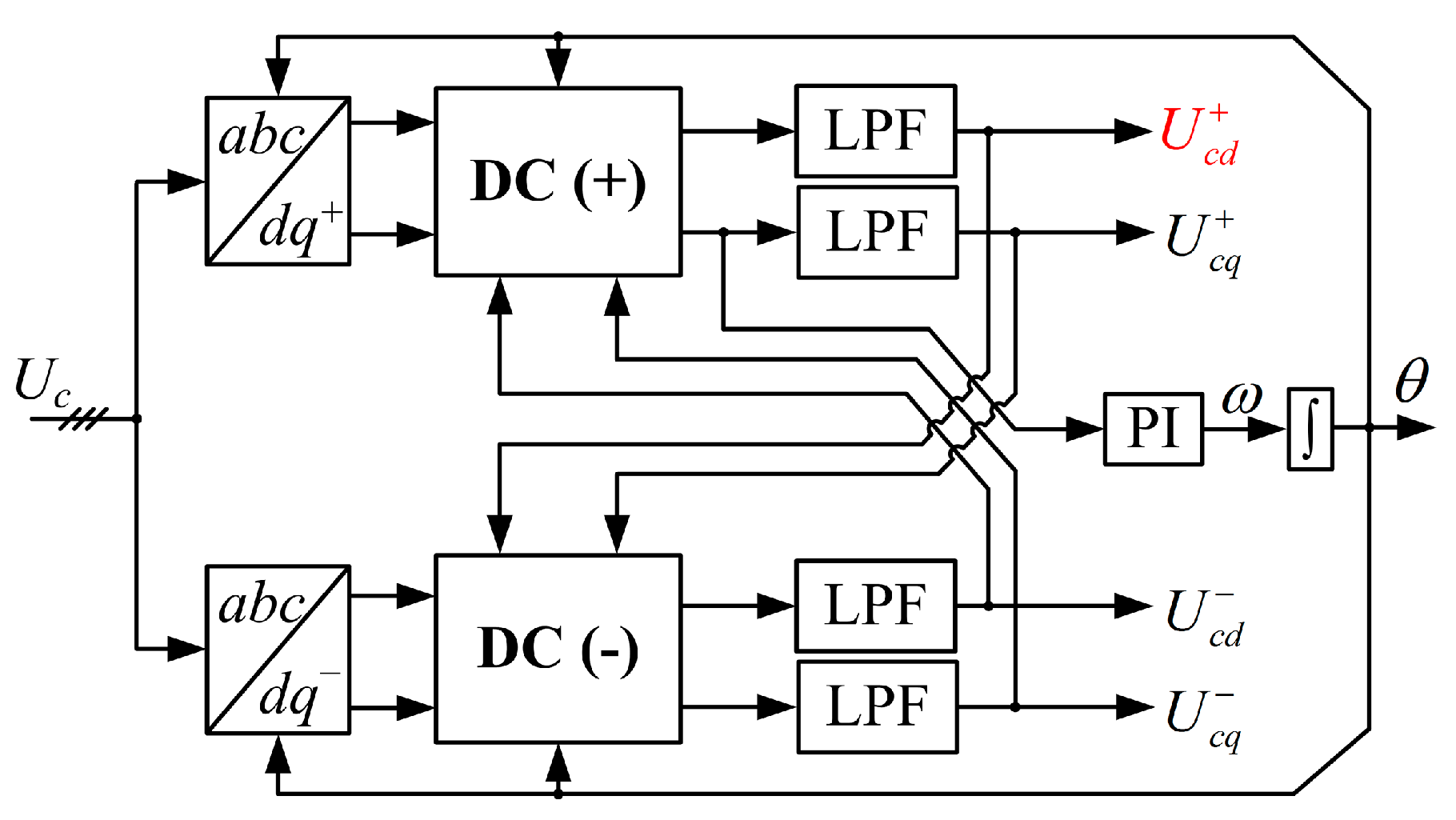
d-axis fundamental positive-sequence component of filter capacitor voltage is extracted from decoupled double synchronous reference frame phase-locked loop (DDSRF-PLL) [
23], which uses the filter capacitor voltage for grid synchronization, the proposed method does not increase the extra sensors and software resources.
This paper is organized as follows. In
Section 2, the mechanism of start-up inrush current is analyzed in detail. Then, the filter capacitor voltage feedforward, which is used to suppress start-up inrush current, is analyzed. In
Section 3, DFPS-CVFF is proposed, and the influence of different feedforward methods on the system stability under weak grid conditions is analyzed by the impedance model of grid-connected converter. In
Section 4, the experimental and simulation results demonstrate the validity of the proposed method. Finally, some conclusions are summarized in
Section 5.
2. Generation and Suppression Mechanism Analysis of Start-Up Inrush Current
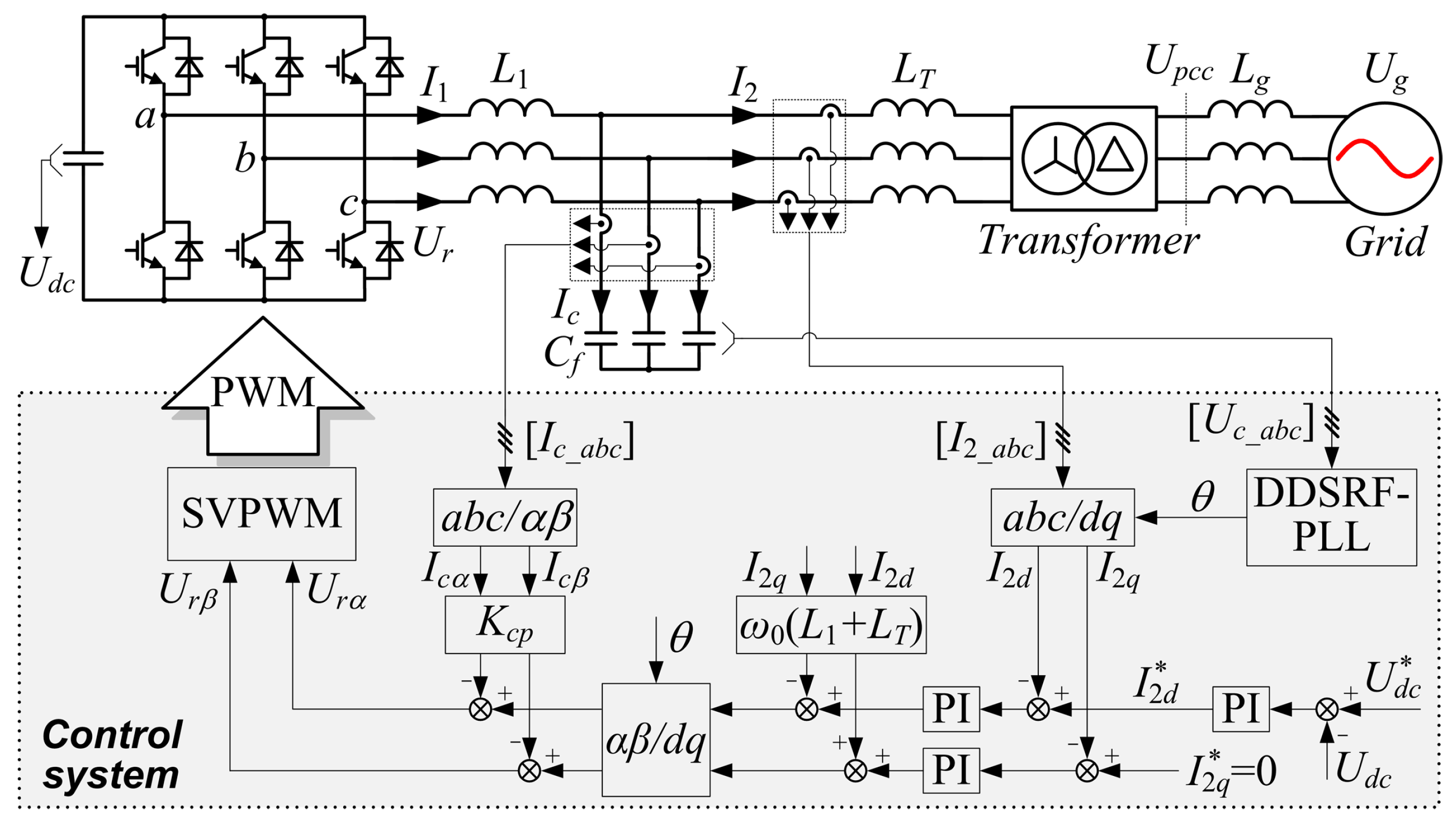
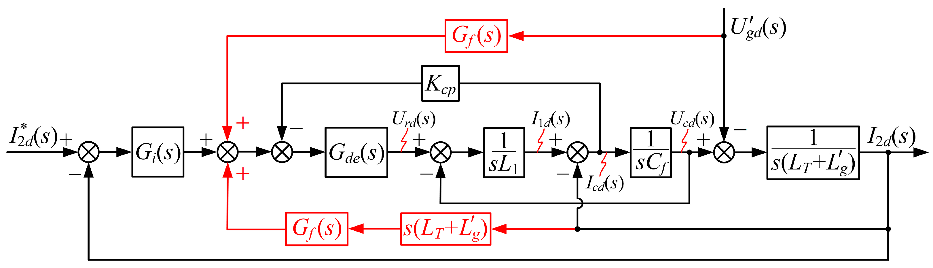
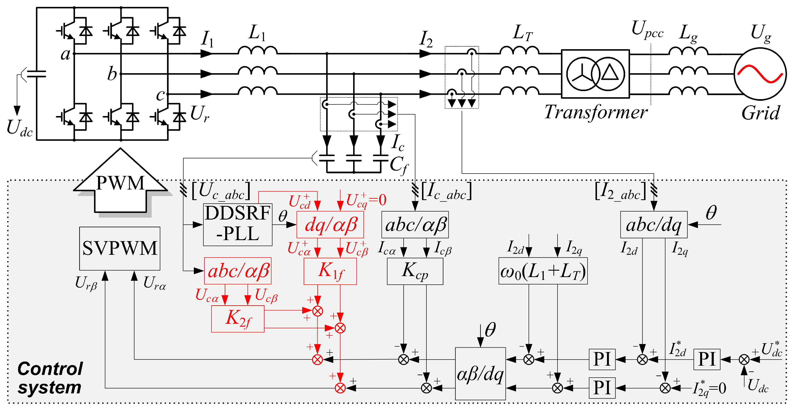
The three-phase LCL-type grid-connected converter topology and its control block in
dq frame are shown in
Figure 2. The LCL filter is composed of the converter side filter inductance
L1, filter capacitor
Cf, and grid side filter inductance
LT, which is the leakage inductance of the isolation transformer. Grid current
I2 is controlled by PI controller, and the capacitor current
Ic feedback active damping is used to suppress the LCL filter resonance peak.
I1 is the converter side current,
Udc is the DC-bus voltage,
Ur is the converter output voltage, and
Upcc is the PCC voltage. For DPGSs, especially megawatt-level systems, it is relatively difficult to measure the PCC voltage to realize grid synchronization, due to the following reasons [
24]: (1) the isolation transformer may be geographically far from the grid-connected converter; (2) in medium- or high-voltage applications, the PCC voltage is comparatively high, leading to a situation where the signal conditioning circuit can be quite complex and expensive; and (3) the grid side inductance of the LCL filter might be replaced by the leakage inductance of the isolation transformer to reduce the volume and cost, as in the system described in this paper. Therefore, as applied in [
13,
24,
25], filter capacitor voltage
Uc is used as the input voltage of DDSRF-PLL. Moreover, a weak grid can be denoted by the Thevenin equivalent circuit, in which an ideal grid voltage
Ug is in series with the grid impedance
Lg. The parameters of transformer high-voltage side
Ug,
Upcc and
Lg are
U’g,
U’pcc and
L’g after being converted to the transformer low-voltage side.
2.1. Generation Mechanism Analysis of the Start-Up Inrush Current
Here,
d-axis is used as an example. According to the main circuit of
Figure 2, applying Kirchhoff’s laws and Clarke transformation, (1) and (2) can be obtained:
where
L2 =
LT +
L’g is the grid side equivalent inductance and
ω0 is the fundamental angular frequency. Subscripts “
d” and “
q” denote the
d- and
q-axis components, respectively.
Bellow the resonant frequency, the LCL filter behaves as an
L filter. Therefore, by combining (1) and (2), the relationships among the grid voltage disturbances, the converter output control voltage and the current can be obtained, as shown in (3). It can be seen that the variety of grid current is determined by the
Urd and
.
In
Figure 2, the capacitor current feedback active damping in
αβ frame can be equivalent to that in
dq frame. Therefore, the control voltage
Urd of current loop output can be expressed as:
where
Kp and
Ki are the proportional coefficient and integral coefficient, respectively, of the grid current PI controller.
Kcp is the capacitor current feedback coefficient.
Ts is sampling period.
Since the reference direction of grid current is from the converter to the grid, the grid current reference is negative when running in rectifier mode. According to (4), at the start time, since the I2d and Icd are very small, Urd is negative. Then, according to (3), L2dI2d/dt + L1dI1d/dt will be large, and the current will increase quickly because of the superposition of Urd and . For the same trend of I2d and I1d, the grid current I2d will increase rapidly, which leads to inrush current. Under weak grid conditions, the larger the grid inductance is (the larger L2 is), the smaller dI2d/dt and inrush current will be. It can be concluded that, when grid voltage disturbance and converter output control voltage are in the same direction, the superposition of the two items will result in inrush current.
Then,
Urd has a process from negative to positive. When the
Urd is equal to
, the inrush current reaches the maximum value, which can be expressed as:
In fact, according to (3) and (4), even if the current reference = 0 when the converter starts; due to the disturbance of grid voltage and small values of I2d and Icd, the inrush current will also be aroused, but the inrush current peak is smaller than when current reference is negative. Therefore, start-up inrush current is not particularly dependent on the current reference.
Moreover, when the grid-connected converter starts in inverter mode, the current reference is positive. According to (4), due to the small values of I2d and Icd at start time, the Urd is positive. Then, according to (3), L2dI2d/dt + L1dI1d/dt will be much smaller than that when converter starts in rectifier mode. Therefore, the inrush current is much smaller when the converter starts in inverter mode than that when converter starts in rectifier mode.
Since d-axis voltage is orientated on the grid voltage vector for control, q-axis grid voltage is zero. Therefore, the q-axis grid voltage does not cause disturbance to the grid current control, thus the start-up inrush current is mainly caused by d-axis voltage.
2.2. Suppression Mechanism Analysis of the Start-Up Inrush Current
For the above analysis, grid voltage disturbance is the primary cause of the start-up inrush current. Therefore, if this disturbance can be offset, the inrush current can be fundamentally suppressed. However, it is relatively difficult to measure the grid voltage or PCC voltage [
24] as in the previous analysis, and therefore the filter capacitor voltage feedforward can be used to suppress the inrush current, since it is linear with the PCC voltage [
13].
With the filter capacitor voltage feedforward compensation, the control voltage
U′rd of current loop output can be expressed as:
where
Gf is the feedforward function.
When the converter starts in rectifier mode, (7) can be obtained by combining (3), (4), (6) and (1).
Comparison between (7) and (3) shows that, due to the same trends of
I2d and
I1d, with filter capacitor voltage feedforward, when
Gf =
Kf = 1 (
Kf is the feedforward proportional coefficient), the grid voltage disturbance is offset, and then
L1dI1d/
dt will be smaller, the change rate of
I2d will be significantly decreased, and the inrush current will not be aroused. Under weak grid conditions, i.e., large
L2, according to (7), the filter capacitor voltage feedforward can also offset the grid voltage disturbance, and the inrush current can similarly be suppressed. When
Kf is decreased from 1 to 0, due to the partial offset of grid voltage disturbance, the change rate of
I2d will be increased, and the inrush current suppression result will deteriorate. When
Kf > 1, the grid voltage disturbance will be over-offset, which is not conducive to the dynamic performance and stability of the system. Therefore,
Gf =
Kf = 1 is selected, and the maximum
I2d is:
When the grid-connected converter starts in inverter mode or current reference = 0, (7) can be derived similarly. It also can be seen that the grid voltage disturbance can be effectively offset by capacitor voltage feedforward, so that the converter can also start without inrush current.
The filter capacitor voltage feedforward can offset the grid voltage disturbance and suppress the inrush current effectively. However, many grid current harmonics will be aroused and the system stability will deteriorate when the filter capacitor voltage feedforward is introduced under weak grid conditions. Therefore, in the next Section, the DFPS-CVFF will be proposed to suppress start-up inrush current without affecting the system stability under weak grid conditions.
4. Experimental and Simulation Results
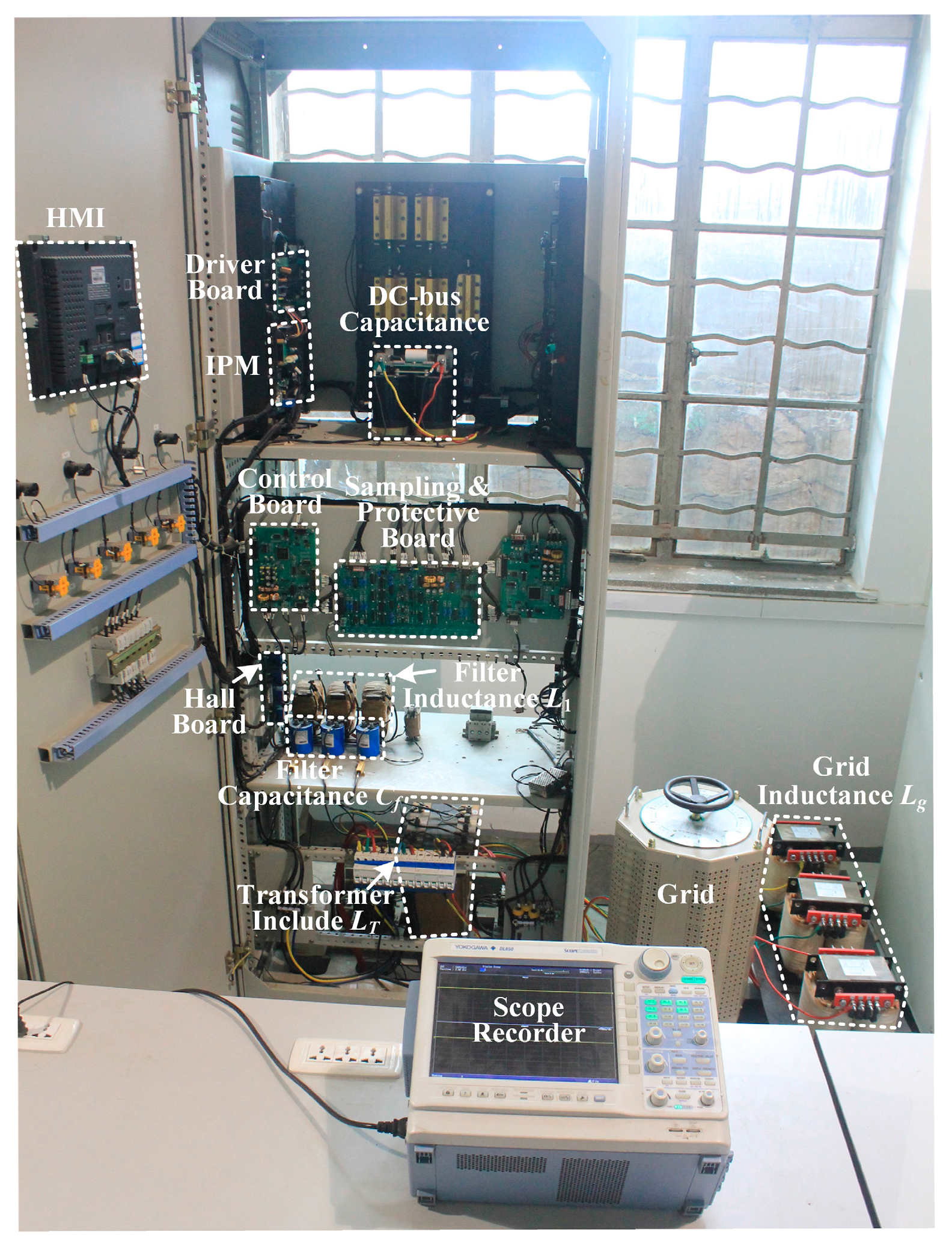
To verify the above theoretical analysis, a prototype of a 10 kW three-phase LCL-type grid-connected converter is built, as shown in
Figure 10. The topology is shown in
Figure 2, and its parameters are listed in
Table 1. The converter is implemented using an intelligent power module (IPM) (PM100RL1A120, Mitsubishi, Tokyo, Japan). The current and voltage are sensed by the halls (LA58-P, Lem, Beijing, China and CLSM-05MA, Sypris, Orlando, FL, USA). The control strategy is implemented in a DSP (TMS320F28335, Texas Instruments, Dallas, TX, USA). All the signals are sampled by a 12-bit A/D converter (AD7891, Analog Devices, Norwood, MA, USA). An isolation transformer is placed between the LCL-type grid-connected converter and the grid, and the leakage inductance
LT of the transformer acts as the grid side filter inductance of the LCL filter. An external inductance (
Lg = 4.6 mH and 23.1 mH, corresponding to SCR = 10 and 2, respectively) is used to emulate the weak grid, which is placed in series between the grid and the isolation transformer.
Before converter start, phase locking is achieved, and the calculation of the d-axis fundamental positive-sequence component of capacitor voltage has already been completed.
4.1. Under Normal Grid Voltage Conditions
When grid inductance
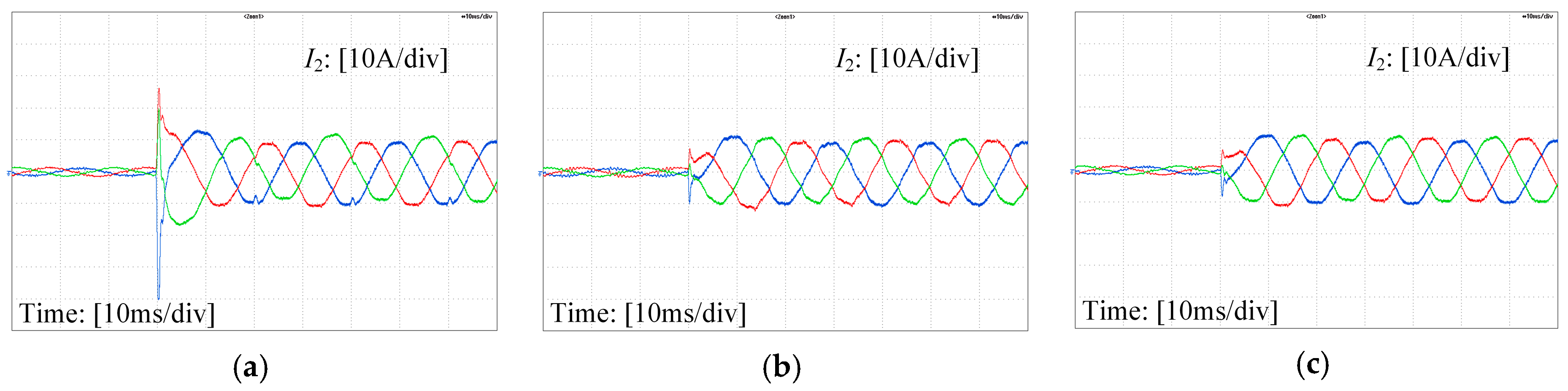
L’g = 0, experimental results of grid-connected converter starts in rectifier mode with NFF, SCVDFF and DFPS-CVFF are shown in
Figure 11. The current reference is −10 A. As shown in
Figure 11a, with NFF, the current peak can reach 40 A, the overshoot is 300%. Obviously, such inrush current may trigger overcurrent protection, and even damage the switching device. However, with feedforward, as shown in
Figure 11b,c, after a short adjustment, the grid current converges smoothly to its reference, and the current peak has been effectively suppressed.
Figure 11b,c also show that, with SCVDFF and DFPS-CVFF, the system has the same start-up inrush current suppression performance. Moreover, SCVDFF and DFPS-CVFF can offset the grid voltage disturbance, and the grid current has the better steady-state control performance compared with NFF.
When grid inductance
L’g = 0, experimental results of the grid-connected converter starting in inverter mode with NFF, SCVDFF and DFPS-CVFF are shown in
Figure 12. The current reference is 10 A. The comparison of
Figure 12a and
Figure 11a shows that the inrush current when the converter starts in inverter mode is much smaller than that when the converter starts in rectifier mode. With SCVDFF and DFPS-CVFF, the disturbance of grid voltage is restrained, and the grid-connected converter has a better start-up dynamic performance, which is consistent with the theoretical analysis.
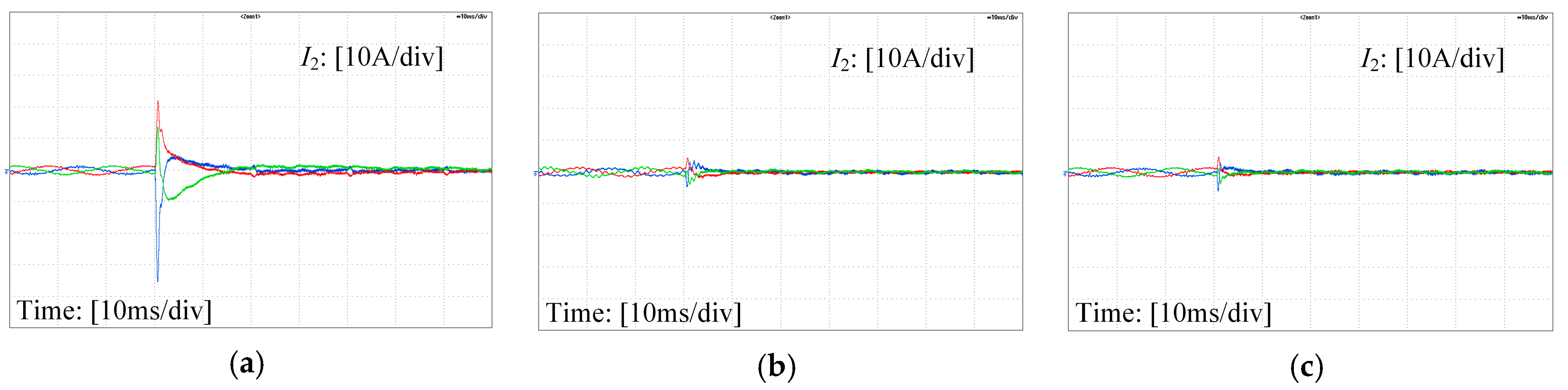
When grid inductance
L’g = 0 and the current reference
= 0, experimental results of the grid-connected converter starting with NFF, SCVDFF and DFPS-CVFF are shown in
Figure 13.
Figure 13a shows that even if the current reference
= 0 when the converter starts, the start-up inrush current is also aroused, and a little smaller than when the current reference is −10 A, as shown in
Figure 11a. This indicates that the start-up inrush current is not particularly dependent on the current reference, which is consistent with the theoretical analysis. The current peak can also be suppressed with SCVDFF and DFPS-CVFF, as shown in
Figure 13b,c.
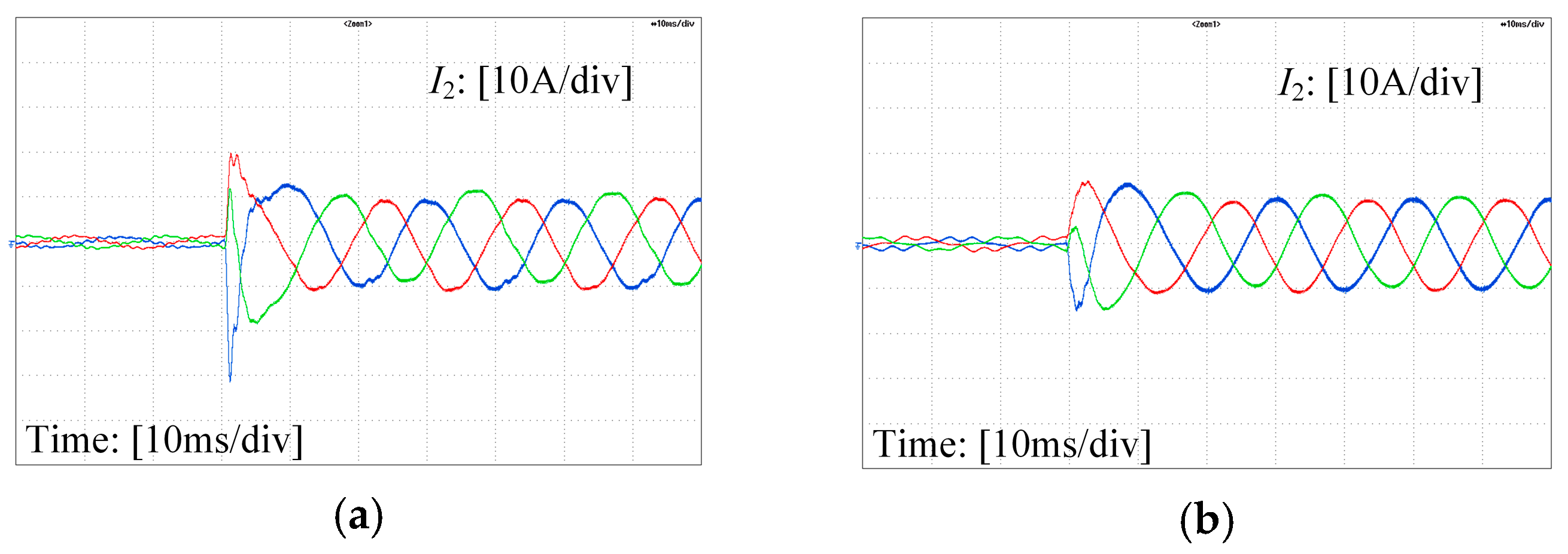
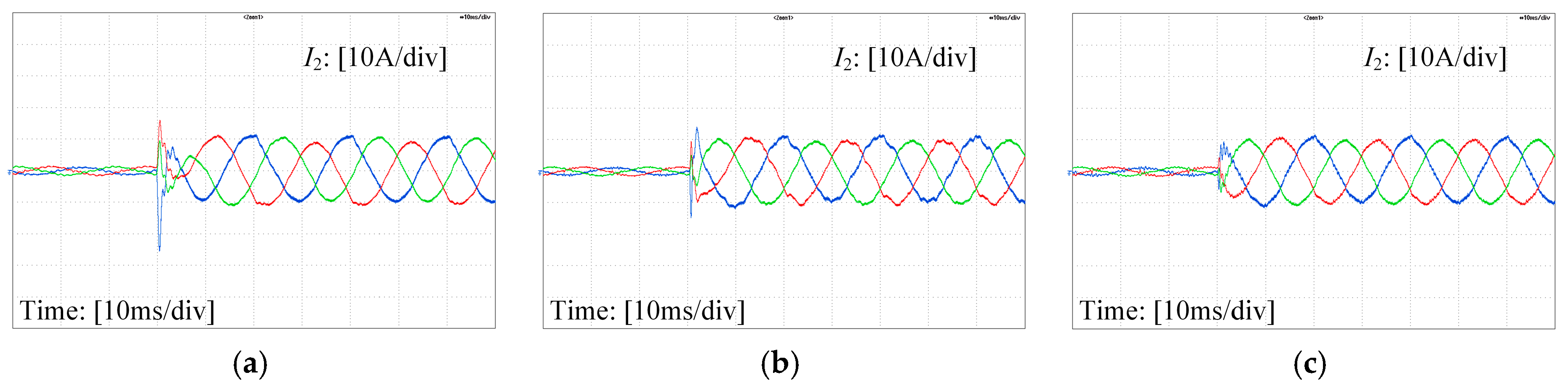
When SCR = 10 and 2, experimental results of grid-connected converter starts in rectifier mode with NFF are shown in
Figure 14, and the FFT analyses are shown in
Figure 15. The comparison of
Figure 14a,b and
Figure 11a shows that, under weak grid conditions, with the increase of grid inductance, the start-up inrush current is smaller, which is consistent with the theoretical analysis.
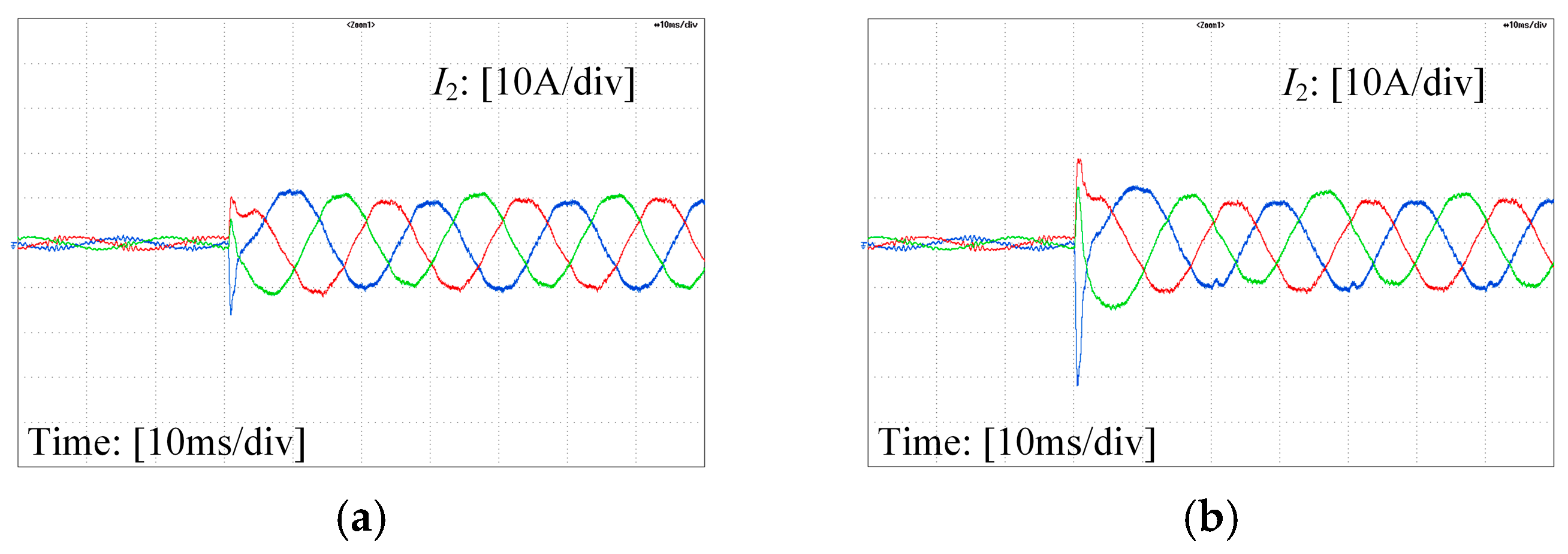
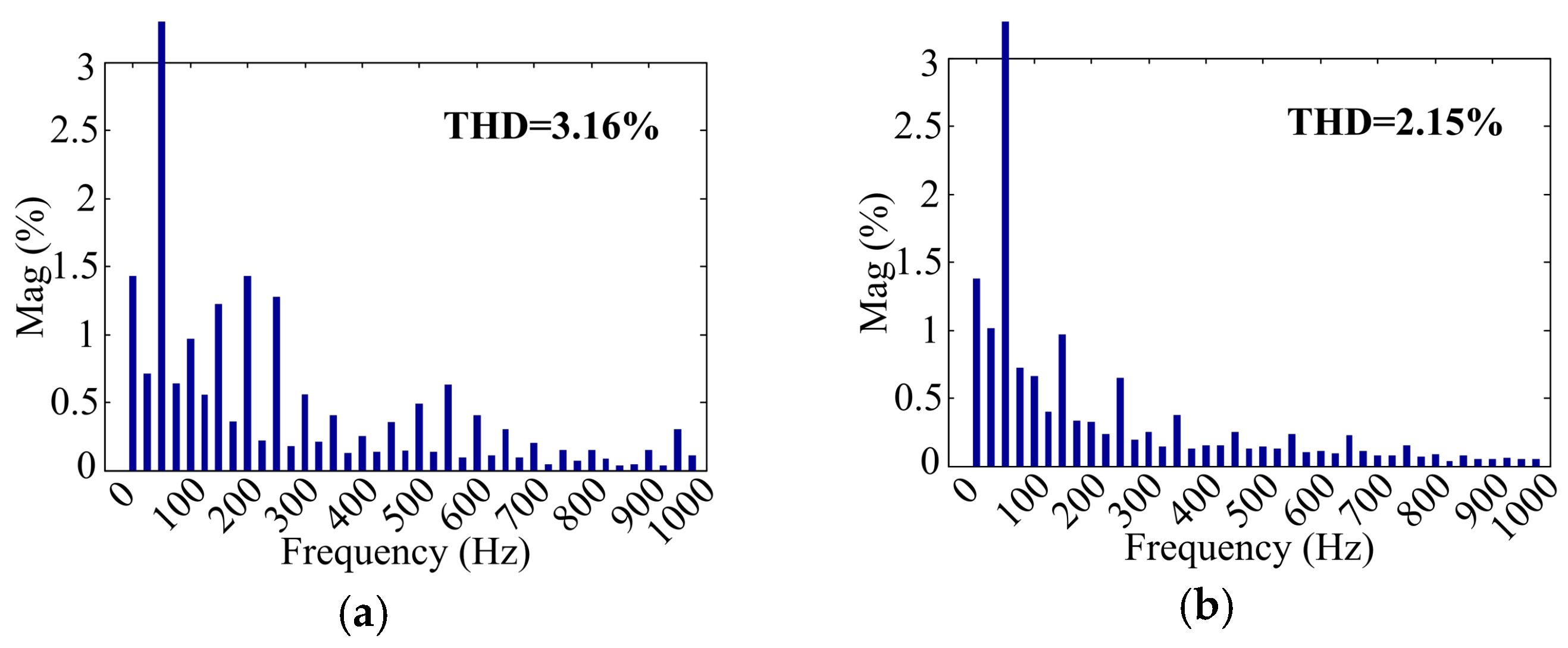
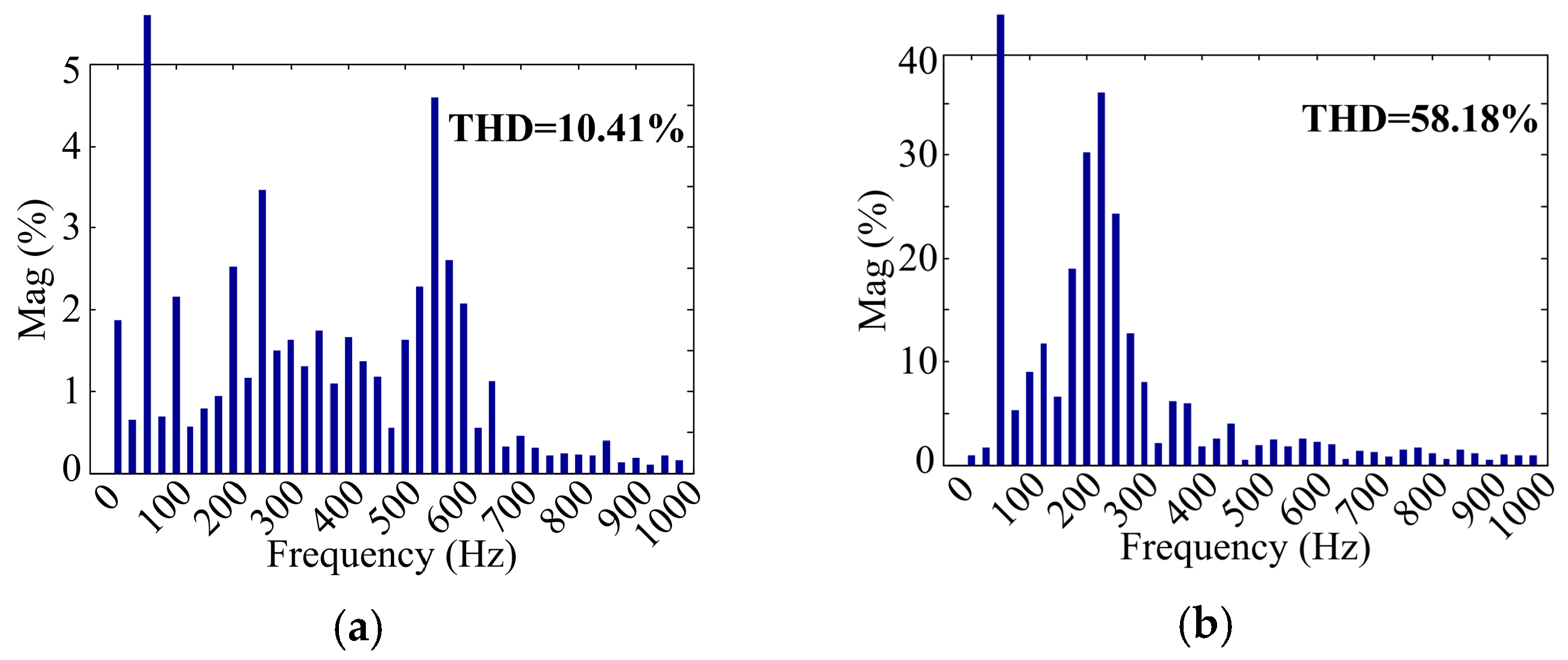
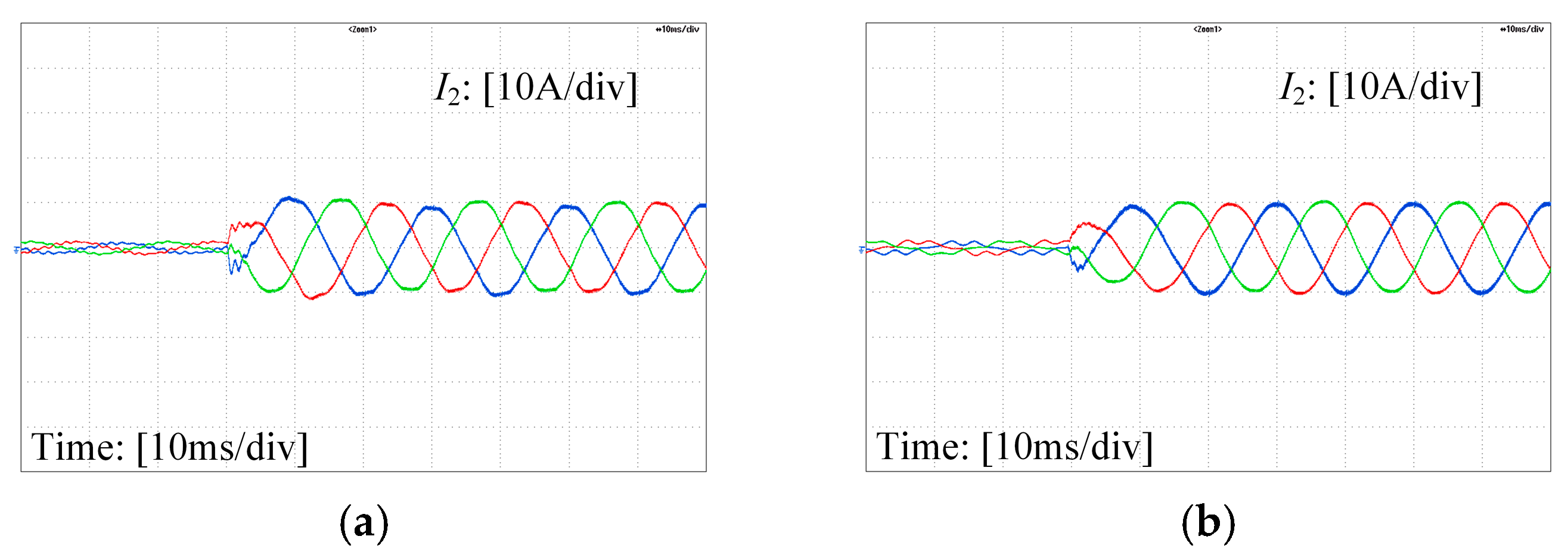
When SCR = 10 and 2, the experimental results for the grid-connected converter starting in rectifier mode with SCVDFF are shown in
Figure 16, and the FFT analyses are shown in
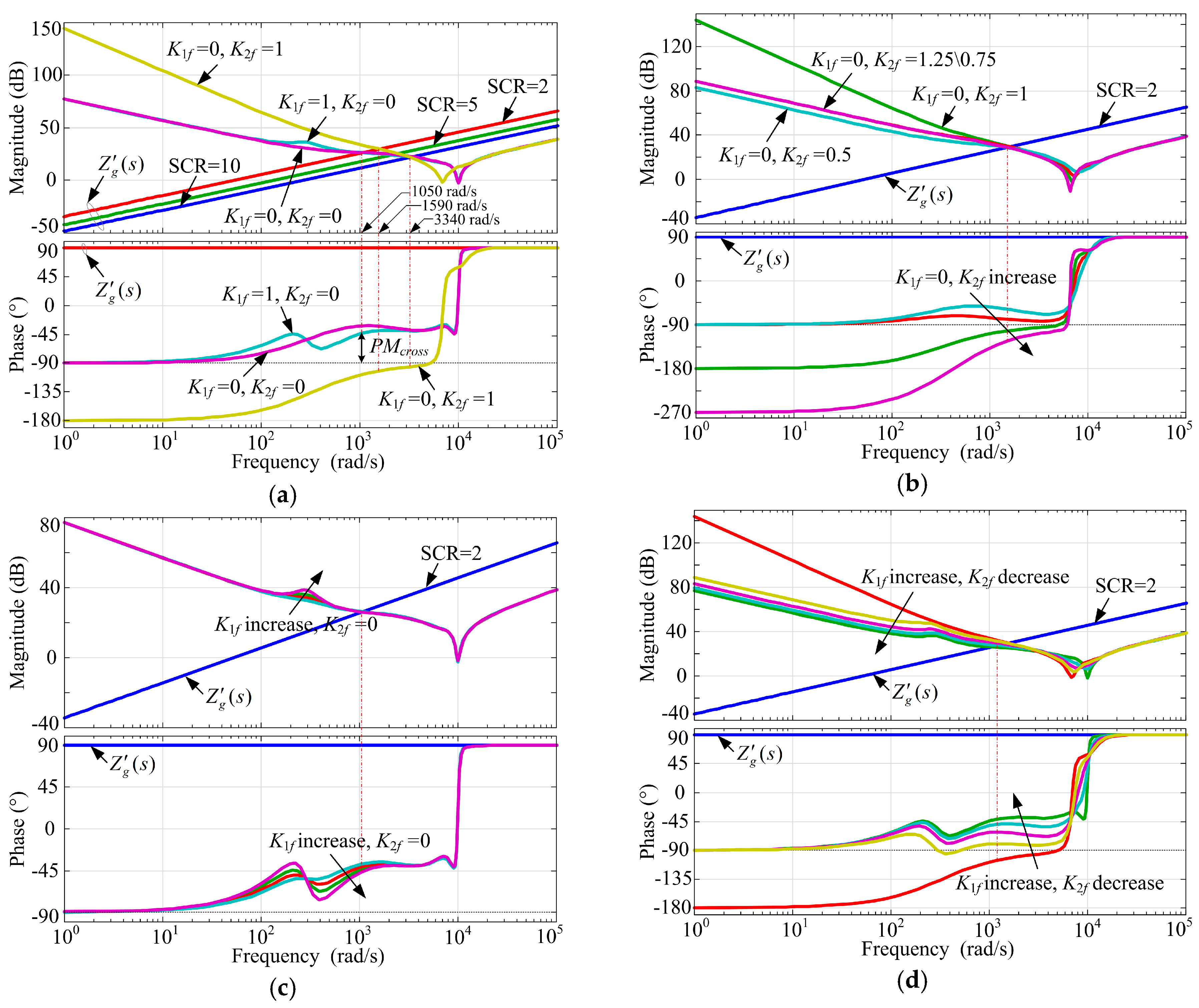
Figure 17. Under weak grid conditions, due to the additional positive feedback loop of grid current, the system does not have a big enough stability margin. Therefore, the grid current has many harmonics and serious distortion. The weaker the grid is, the more serious the grid current distortion will be. Moreover, as shown in
Figure 9a, when SCR = 10 and 2, with SCVDFF, the converter output impedance intersects with the grid impedance around 550 Hz and 250 Hz, and the
PMcross is negative. This explains the distortion of grid current in
Figure 16. FFT analysis of the grid current reveals large harmonics around the 550 Hz and 250 Hz respectively, as shown in
Figure 17, which correlates to the impedance intersection frequency
fcross.
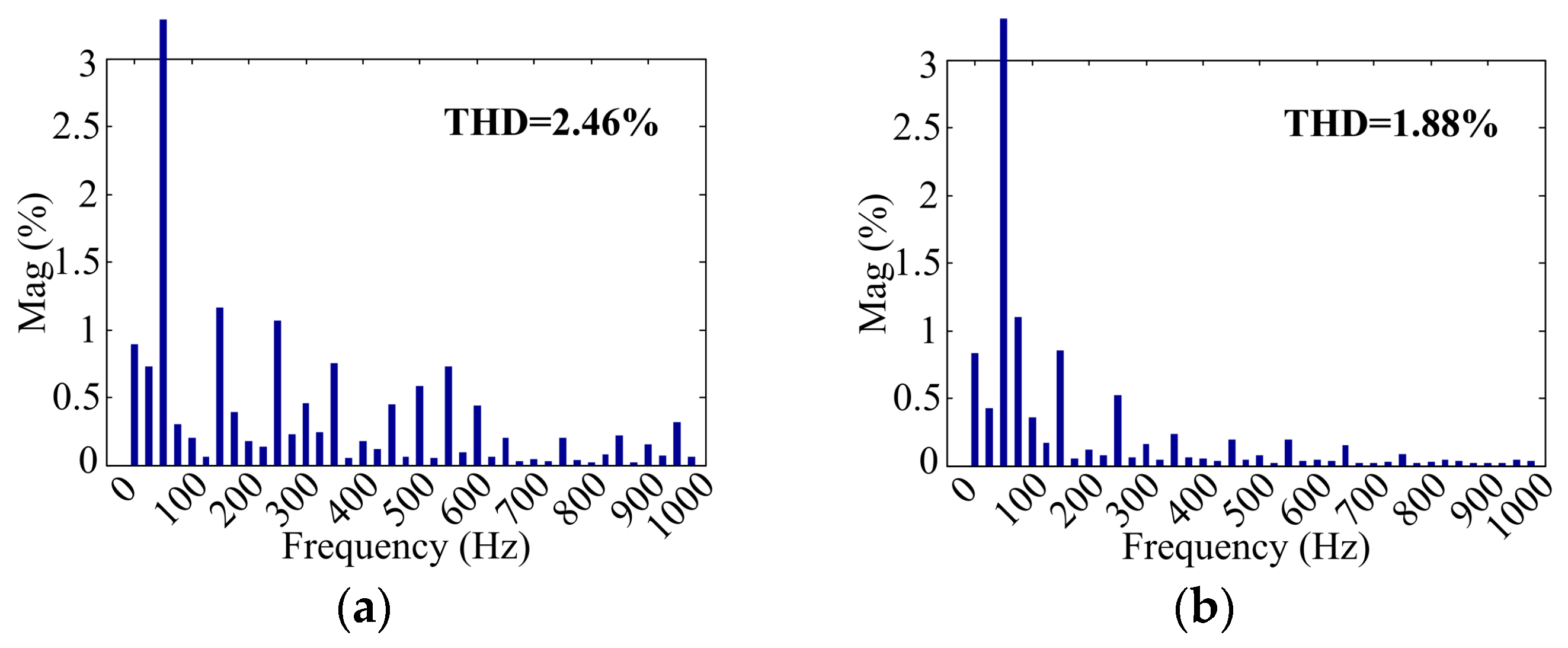
When SCR = 10 and 2, the experimental results for the grid-connected converter starting in rectifier mode with DFPS-CVFF are shown in
Figure 18, and the FFT analyses are shown in
Figure 19. Under weak grid conditions, with DFPS-CVFF, the start-up inrush current can also be suppressed effectively. Since the system has a big enough stability margin, the grid current has better waveform quality compared with SCVDFF, as shown in
Figure 16. The THD are smaller compared with NFF and SCVDFF, as shown in
Figure 15 and
Figure 17. Moreover, the harmonics around the
fcross (550 Hz and 150 Hz) are significantly reduced compared with
Figure 17, as shown in
Figure 19, which illustrates the increase of
PMcross in
Figure 9a.
When grid inductance
L’g = 0 and
K1f = 0,
K2f = 0.75 and 0.25, respectively, the experimental results of the grid-connected converter starting in rectifier mode with SCVDFF are shown in
Figure 20. When grid inductance
L’g = 0 and
K1f = 0.75, 0.25,
K2f = 0, respectively, the experimental results of the grid-connected converter starting in rectifier mode with DFPS-CVFF are shown in
Figure 21. It can be seen that, under stiff grid conditions, the smaller the feedforward coefficient is, the worse the inrush current suppression will be, which is consistent with the above theoretical analysis. Note that, except
Figure 20 and
Figure 21, NFF is
K1f =
K2f = 0, SCVDFF is
K1f = 0,
K2f = 1, and DFPS-CVFF is
K1f = 1,
K2f = 0.
4.2. Unbalanced and Distorted Grid Voltage Conditions
Since the weak grid often involves problems of unbalance and distortion, the effectiveness of the proposed control algorithm under the conditions of unbalanced and distorted grid voltage are also verified.
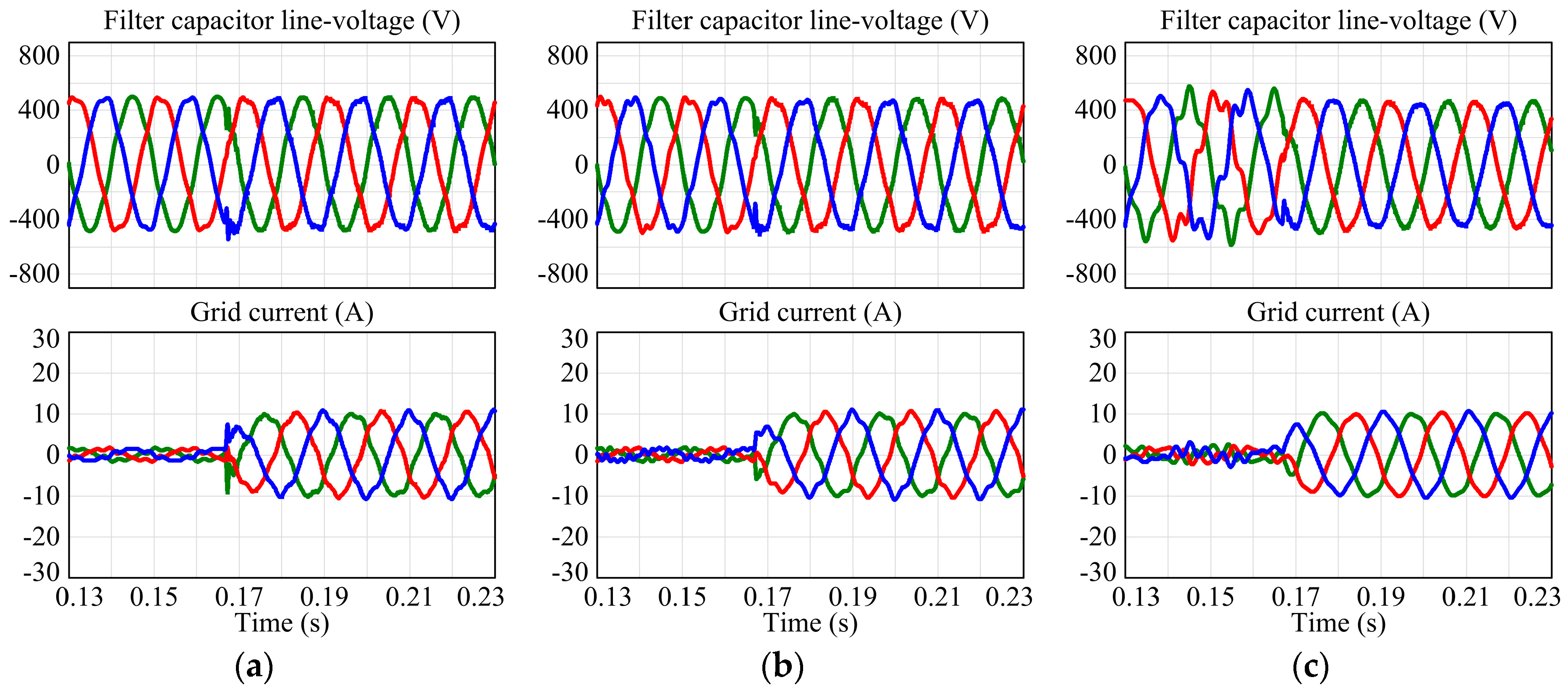
Under unbalanced grid voltage condition, the simulation results of the grid-connected converter starting in rectifier mode with DFPS-CVFF when
L’g = 0, SCR = 10, and SCR = 2, respectively, are shown in
Figure 22. The grid voltage includes 20% voltage amplitude and zero phase shift of negative-sequence components.
Figure 22 shows the filter capacitor line-voltage and grid current. The grid current is balanced, since the double synchronous reference frame PI controller [
29] and DDSRF-PLL are used, and the start-up inrush current can also be suppressed effectively with the proposed method under unbalanced grid conditions.
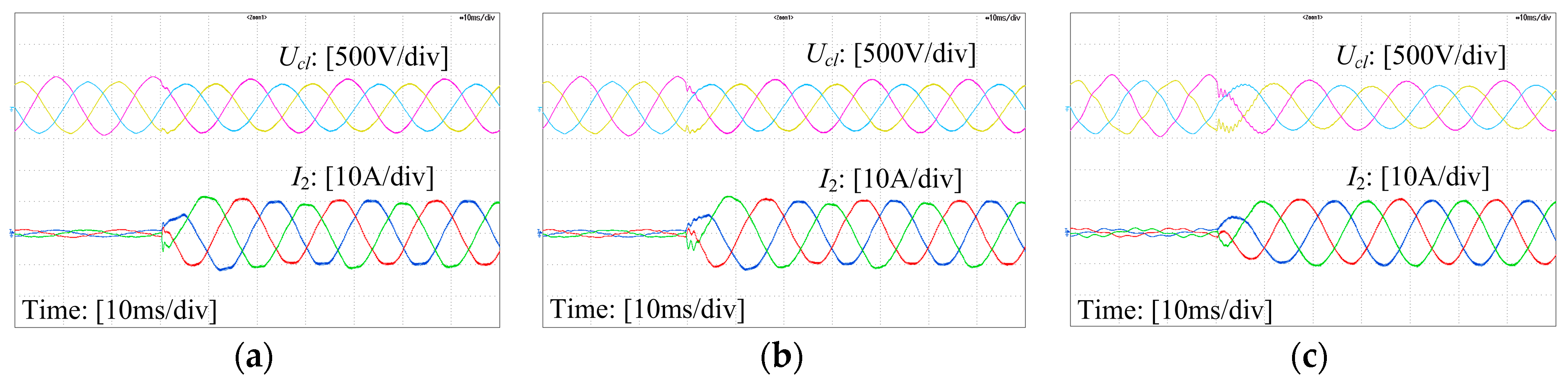
Under unbalanced grid voltage conditions, the experimental results of the grid-connected converter starting in rectifier mode with DFPS-CVFF when
L’g = 0, SCR = 10, and SCR = 2, respectively, are shown in
Figure 23. The phase-A and phase-B grid voltages are both dipped 20% using a grid fault generator [
30].
Figure 23 shows the filter capacitor line-voltage and grid current. Note that the Δ-Y type transformer will cause 30° phase shift of grid voltage and grid current. The experimental results also show that the start-up inrush current can also be suppressed effectively with the proposed method under unbalanced grid conditions.
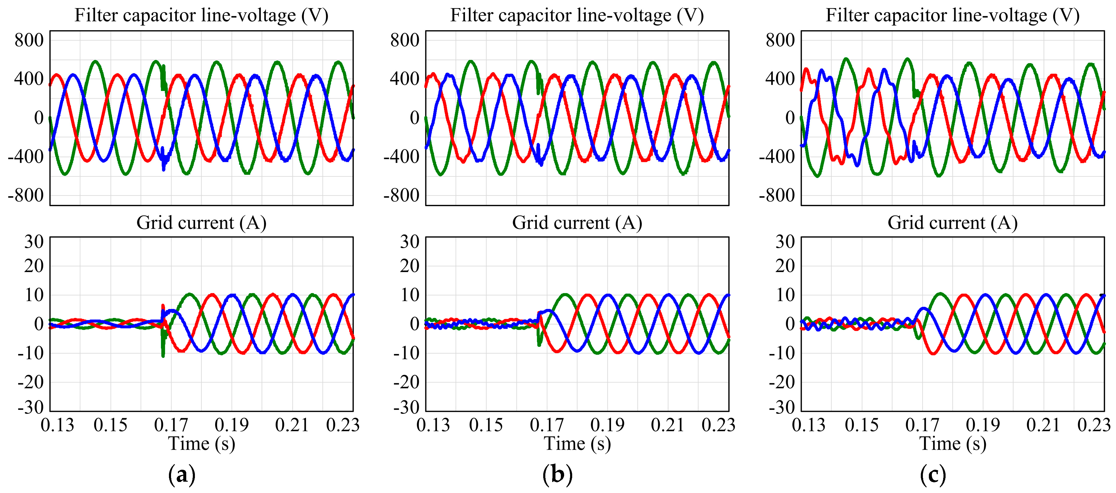
Under distorted grid voltage conditions, the simulation results of the grid-connected converter starting in rectifier mode with DFPS-CVFF when
L’g = 0, SCR = 10, and SCR = 2, respectively, are shown in
Figure 24. The grid voltage is distorted by 3% for fifth harmonics and 2% for seventh harmonics, with zero phase shifts.
Figure 24 shows the filter capacitor line-voltage and grid current. Since the control strategy used in this paper cannot suppress the grid current harmonics caused by distorted grid voltage, there are some low-frequency harmonics in the grid current. However, this paper mainly focuses on start-up inrush current suppression, and the effect of the grid voltage harmonics is beyond its scope. If further low frequency harmonic suppression is desired, other control schemes such as full-feedforward of grid voltages [
11] or multiple proportional-resonant (PR) compensators [
12] could be introduced. Moreover,
Figure 24 also shows that the start-up inrush current can also be suppressed effectively with the proposed method under distorted grid conditions.


