A UAV Vision-Based Deformation Monitoring Method with 3D Scale Constraints


Highlights
- What is the main finding?
- The study developed a spatial 3D scale that provides high-precision scale infor-mation and proposed a UAV visual deformation monitoring method with 3D scale constraints.
- What are the implications of the main findings?
- This method effectively addresses the scale difference between the survey area model and the real model caused by low-quality images and low-precision control points, meeting the needs of high-precision engineering defor-mation monitoring.
- The spatial 3D scale has low production cost and simple on-site deployment, which enhances the applicability of UAV visual deformation monitoring and pro-vides a reliable solution for large-scale deformation monitoring.
Abstract
1. Introduction
2. Materials and Methods
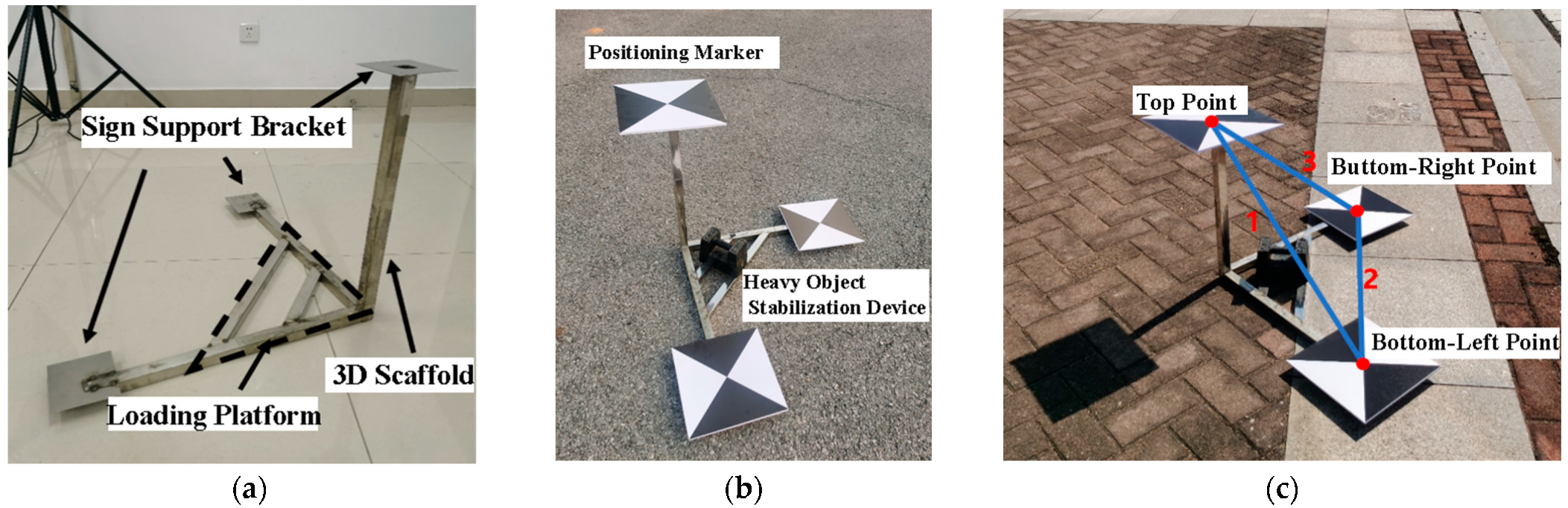
2.1. Development of Three-Dimensional Spatial Ruler
Error Propagation Model
2.2. Control Point Constraints
- (1)
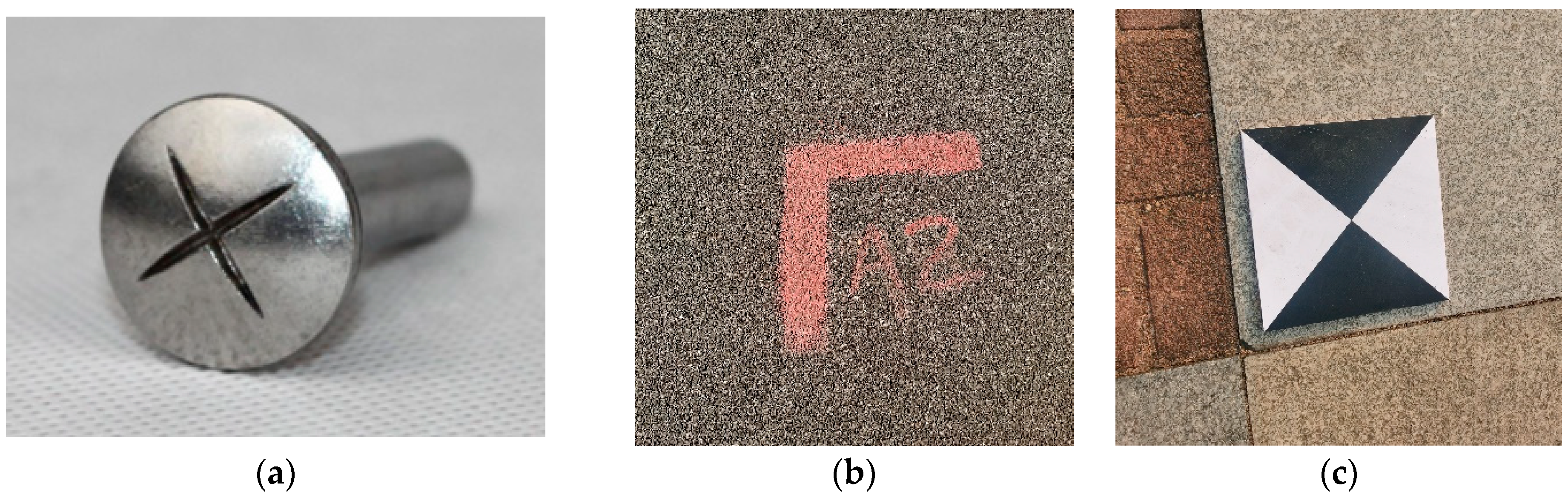
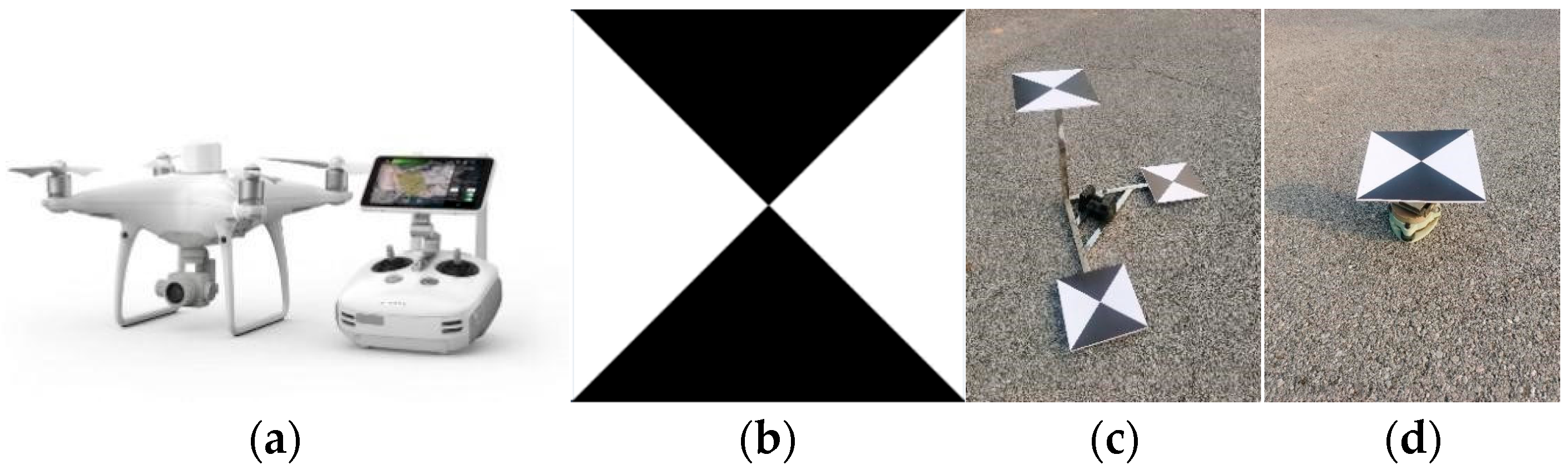
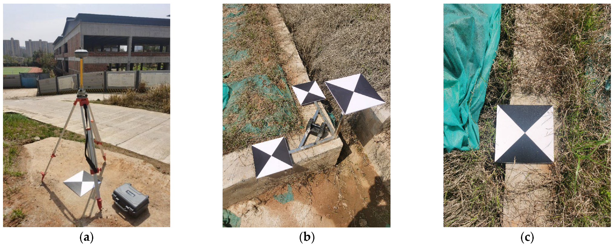
- Clear position. Cross-shaped markers with clear center positions are used as the position carriers of control points. Compared with markers such as building corners and intersections selected in non-visual ways, they have more identifiable features, and their structure is conducive to computer algorithm recognition, with greater advantages in automated position extraction.
- (2)
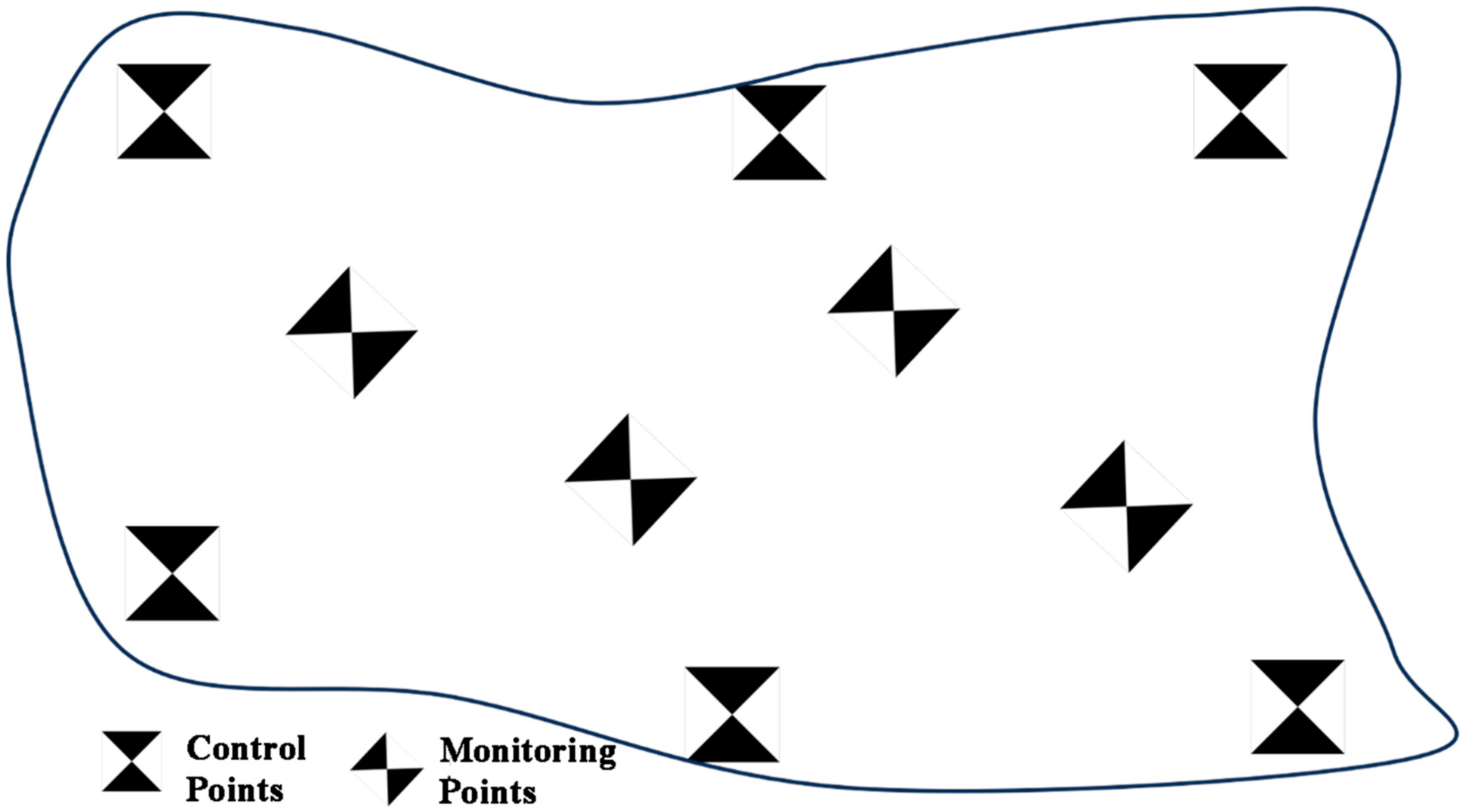
- Uniform distribution. Control points should be evenly distributed in the measurement area to avoid concentrated layout in a certain area, ensuring the accuracy of subsequent 3D modeling.
- (3)
- High point accuracy. The coordinate measurement results of control points should have high precision and reliability, and total stations, GNSS measurement equipment, and RTK receiving equipment can be used for control point position measurement.
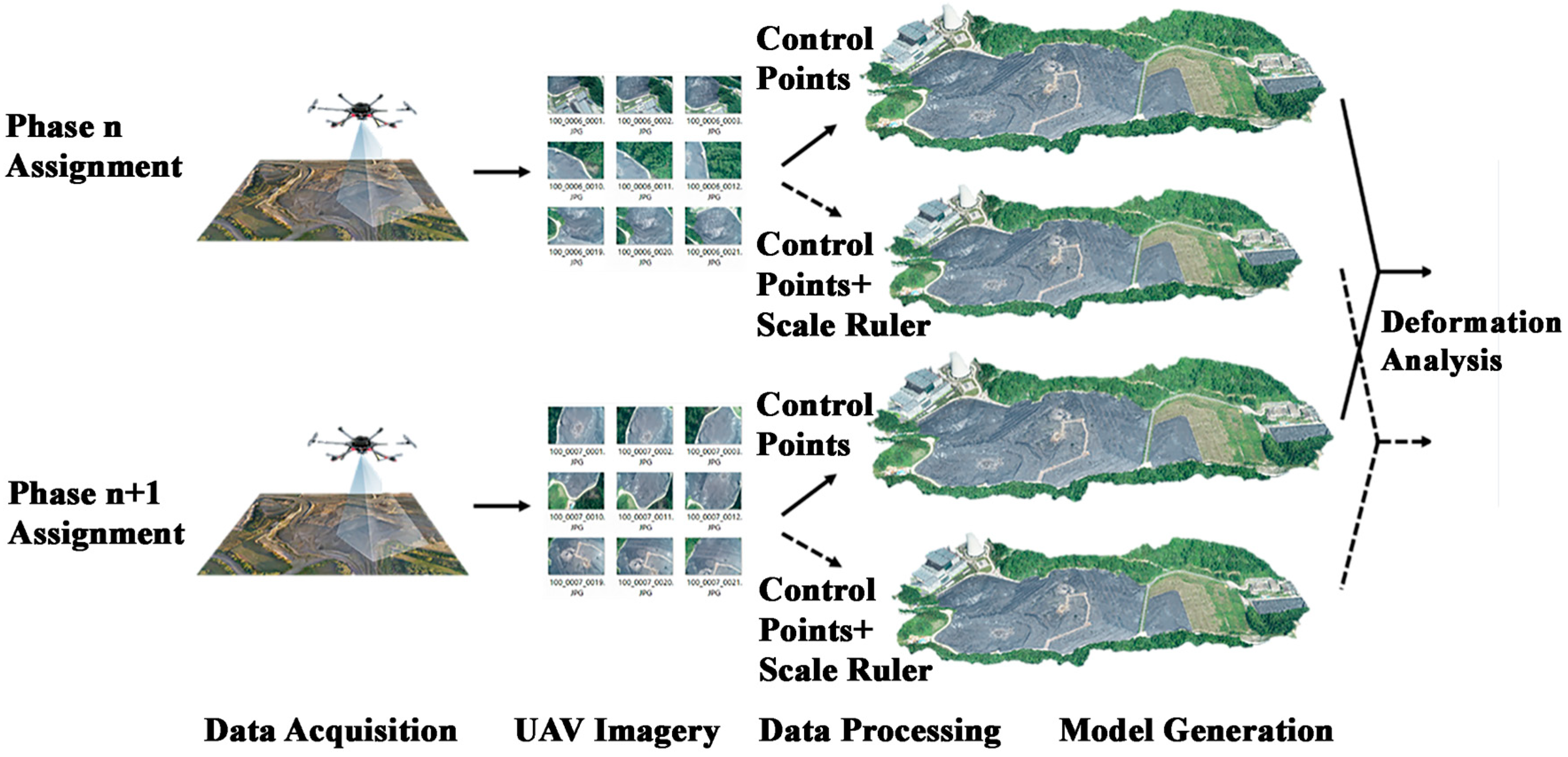
2.3. Workflow of the UAV Vision-Based Deformation Monitoring Method with 3D Scale Constraints
- (1)
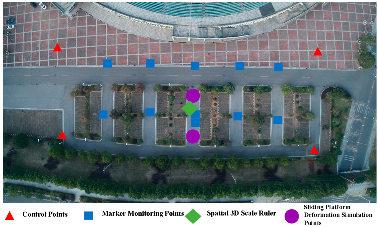
- Layout of points in the survey area: Arrange the spatial 3D scale rulers in unobstructed areas, plan the UAV operation route, and conduct UAV image acquisition.
- (2)
- Image quality evaluation: Disable low-quality images (image quality lower than 0.7) in subsequent processing and reconstruct a rough model using UAV POS data.
- (3)
- Use Metashape software (v. 2.2.1) to manually locate the positions of feature points such as control points and scale ruler points, construct spatial 3D scale rulers, calculate the scale conversion coefficient according to Equation (3), and scale the generated model to the real-world coordinate system.
- (4)
- Use the adaptive Radon transform marker detection and positioning method to perform high-precision repeated positioning of the markers in step (3) to obtain high-precision and highly consistent marker coordinates.
- (5)
- Export the 3D coordinates of monitoring points in the current phase. Repeat steps (1) to (4) to obtain the 3D coordinates of monitoring points in the next phase, and calculate the difference between the coordinates of the two phases to obtain the deformation value of the two phases of monitoring.
- (1)
- Image collection: UAV data collection.
- (2)
- Calculation of detection parameters: After obtaining information (marker size W, UAV flight height H, ratio s of the center line length to the side length of the marker, focal length f and pixel size u of the UAV vision sensor), calculate the marker information collection radius R and the edge width L of the cross-shaped scoring template, where the calculation formulas of R and L are:where .
- (3)
- Marker detection and positioning: Obtain a saliency map using the Radon transform, locate peak points through surface fitting, and finally obtain the marker positioning results.
2.4. Calculation of Deformation Monitoring Results
3. Experiment Design and Result
3.1. UAV 3D Deformation Monitoring Experiment
Experimental Results and Analysis
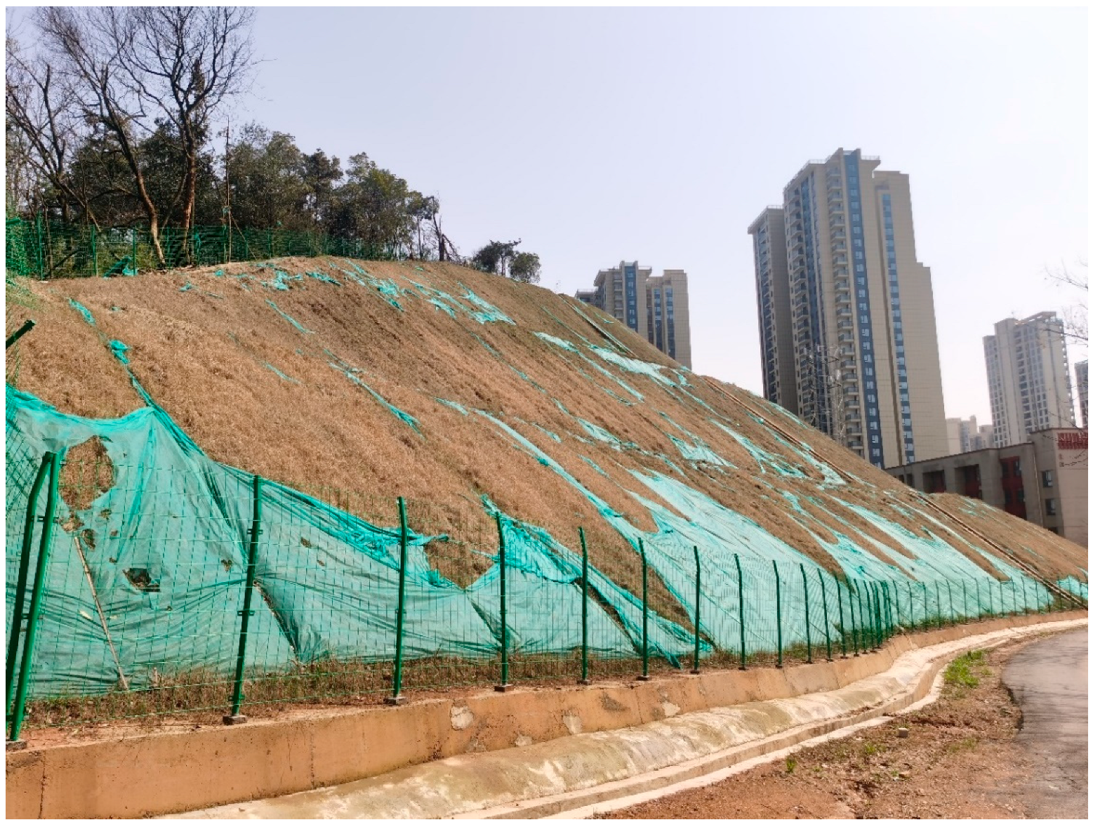
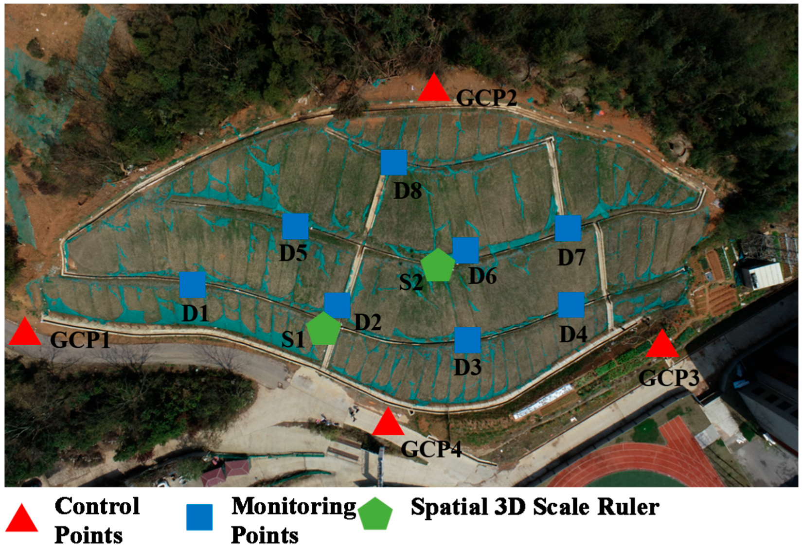
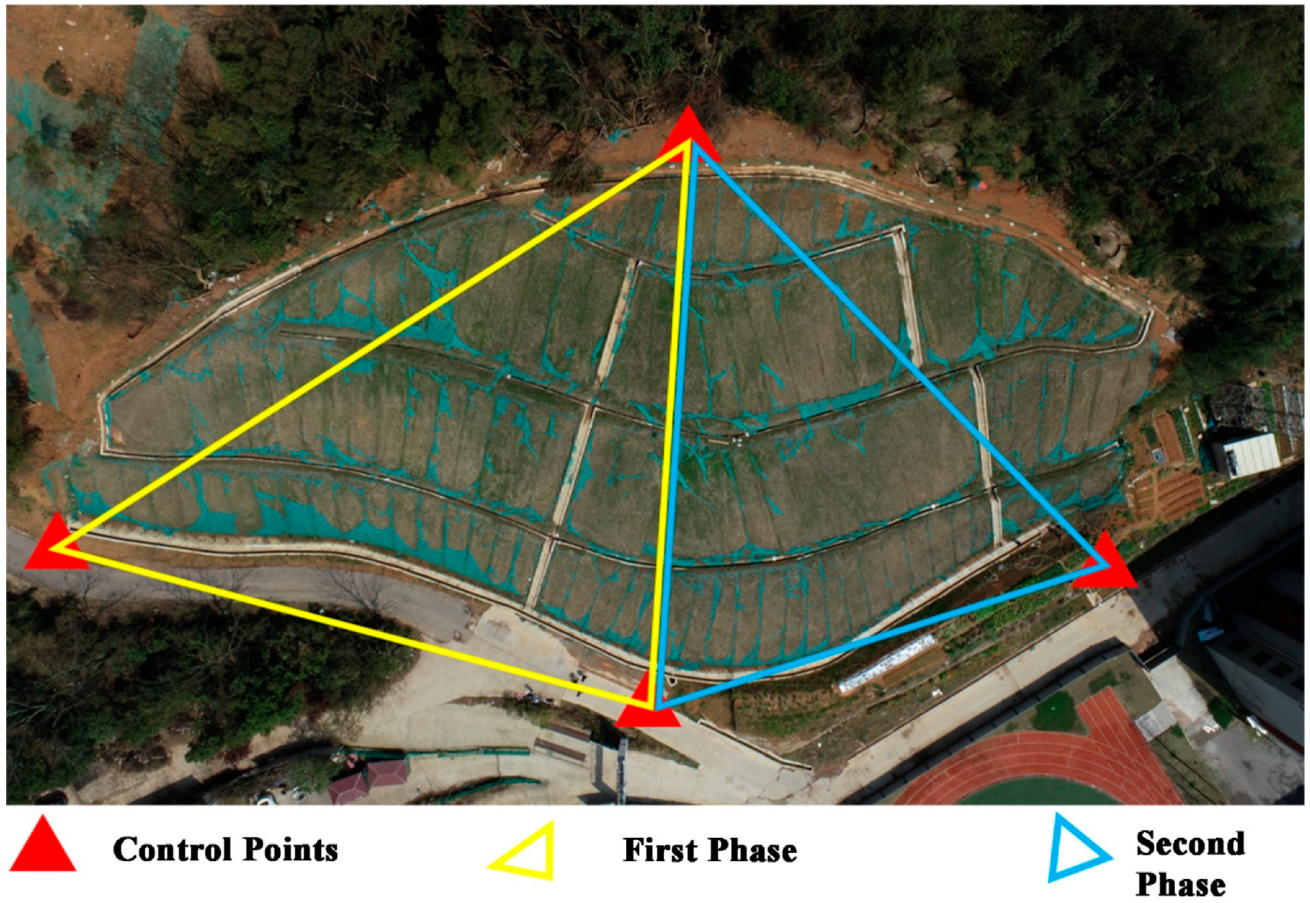
3.2. Landslide Monitoring Experiment at the Northwest Corner of Chuangyuan Primary School in Kaifu District, Changsha City
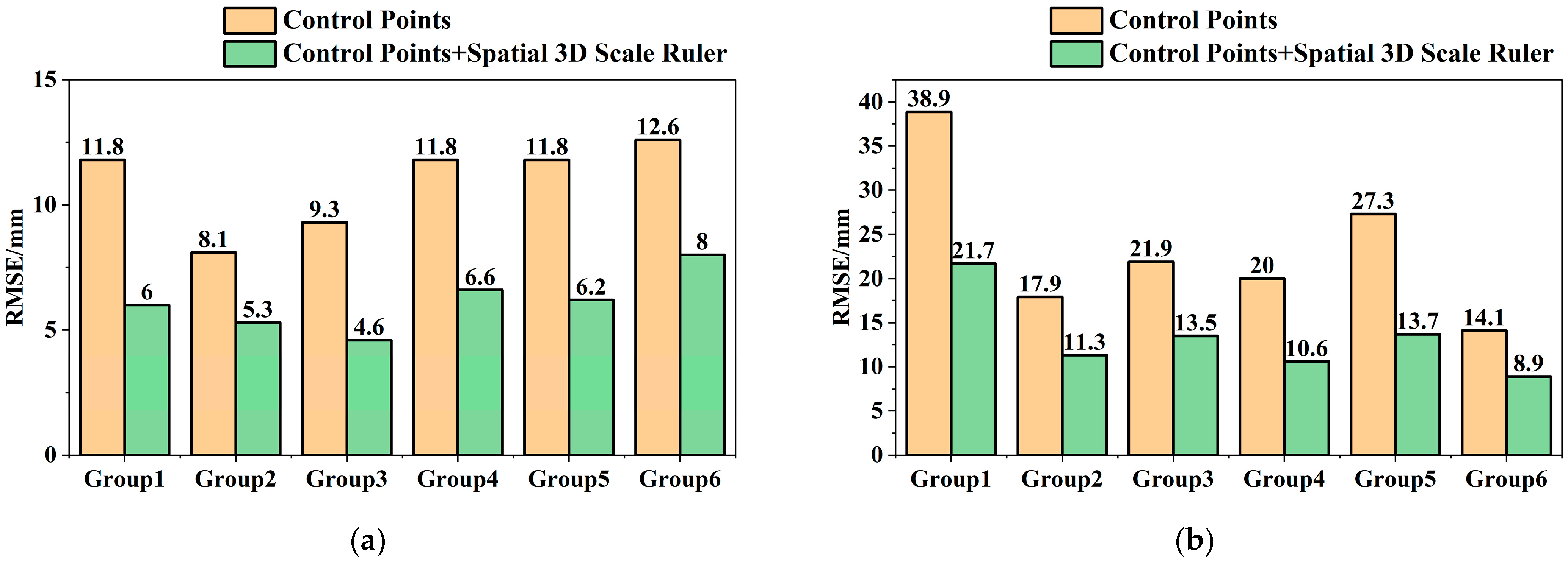
Experimental Results and Analysis
4. Discussion
Author Contributions
Funding
Institutional Review Board Statement
Informed Consent Statement
Data Availability Statement
Acknowledgments
Conflicts of Interest
Abbreviations
| UAV | Unmanned Aerial Vehicle |
| SfM | Structure from Motion |
| 3D | Three-Dimensional |
| GSD | Ground Sampling Distance |
References
- Dandoš, R.; Mozdřeň, K.; Staňková, H. A New Control Mark for Photogrammetry and Its Localization from Single Image Using Computer Vision. Comput. Stand. Interfaces 2018, 56, 41–48. [Google Scholar] [CrossRef]
- Taşçi, L. Deformation Monitoring in Steel Arch Bridges through Close-Range Photogrammetry and the Finite Element Method. Exp. Tech. 2015, 39, 3–10. [Google Scholar] [CrossRef]
- Xin, W.; Pu, C.; Liu, W.; Liu, K. Landslide Surface Horizontal Displacement Monitoring Based on Image Recognition Technology and Computer Vision. Geomorphology 2023, 431, 108691. [Google Scholar] [CrossRef]
- Guan, L.; Chen, Y.; Liao, R. Accuracy Analysis for 3D Model Measurement Based on Digital Close-Range Photogrammetry Technique for the Deep Foundation Pit Deformation Monitoring. KSCE J. Civ. Eng. 2023, 27, 577–589. [Google Scholar] [CrossRef]
- Moulon, P.; Monasse, P.; Marlet, R. Global Fusion of Relative Motions for Robust, Accurate and Scalable Structure from Motion. In Proceedings of the IEEE International Conference on Computer Vision, Sydney, Australia, 1–8 December 2013; pp. 3248–3255. [Google Scholar]
- Zhu, S.; Zhang, R.; Zhou, L.; Shen, T.; Fang, T.; Tan, P.; Quan, L. Very Large-Scale Global Sfm by Distributed Motion Averaging. In Proceedings of the IEEE Conference on Computer Vision and Pattern Recognition, Salt Lake City, UT, USA, 18–22 June 2018; pp. 4568–4577. [Google Scholar]
- Parente, L.; Chandler, J.H.; Dixon, N. Optimising the Quality of an SfM-MVS Slope Monitoring System Using Fixed Cameras. Photogramm. Rec. 2019, 34, 408–427. [Google Scholar] [CrossRef]
- Peppa, M.V.; Mills, J.P.; Moore, P.; Miller, P.E.; Chambers, J.E. Automated Co-registration and Calibration in SfM Photogrammetry for Landslide Change Detection. Earth Surf. Process. Landf. 2019, 44, 287–303. [Google Scholar] [CrossRef]
- Esposito, G.; Salvini, R.; Matano, F.; Sacchi, M.; Danzi, M.; Somma, R.; Troise, C. Multitemporal Monitoring of a Coastal Landslide through SfM-derived Point Cloud Comparison. Photogramm. Rec. 2017, 32, 459–479. [Google Scholar] [CrossRef]
- Xue, Y.; Zhang, S.; Zhou, M.; Zhu, H. Novel SfM-DLT Method for Metro Tunnel 3D Reconstruction and Visualization. Undergr. Space 2021, 6, 134–141. [Google Scholar] [CrossRef]
- Cardenal, J.; Fernández, T.; Pérez-García, J.L.; Gómez-López, J.M. Measurement of Road Surface Deformation Using Images Captured from UAVs. Remote Sens. 2019, 11, 1507. [Google Scholar] [CrossRef]
- Peppa, M.V.; Mills, J.P.; Moore, P.; Miller, P.E.; Chambers, J.E. Accuracy Assessment of a UAV-Based Landslide Monitoring System. Int. Arch. Photogramm. Remote Sens. Spat. Inf. Sci. 2016, 41, 895–902. [Google Scholar] [CrossRef]
- GB 50026-2020; Standard for Engineering Surveying. China Plans Publishing House: Beijing, China, 2020.
- Mosbrucker, A.R.; Major, J.J.; Spicer, K.R.; Pitlick, J. Camera System Considerations for Geomorphic Applications of SfM Photogrammetry. Earth Surf. Process. Landf. 2017, 42, 969–986. [Google Scholar] [CrossRef]
- Dai, W.; Zheng, G.; Antoniazza, G.; Zhao, F.; Chen, K.; Lu, W.; Lane, S.N. Improving UAV-SfM Photogrammetry for Modelling High-relief Terrain: Image Collection Strategies and Ground Control Quantity. Earth Surf. Process. Landf. 2023, 48, 2884–2899. [Google Scholar] [CrossRef]
- O’Connor, J. Impact of Image Quality on SfM Photogrammetry: Colour, Compression and Noise; Kingston University: Kingston, UK, 2018. [Google Scholar]
- Sanz-Ablanedo, E.; Chandler, J.H.; Rodríguez-Pérez, J.R.; Ordóñez, C. Accuracy of Unmanned Aerial Vehicle (UAV) and SfM Photogrammetry Survey as a Function of the Number and Location of Ground Control Points Used. Remote Sens. 2018, 10, 1606. [Google Scholar] [CrossRef]
- Villanueva, J.K.S.; Blanco, A.C. Optimization of Ground Control Point (GCP) Configuration for Unmanned Aerial Vehicle (UAV) Survey Using Structure from Motion (SFM). Int. Arch. Photogramm. Remote Sens. Spat. Inf. Sci. 2019, 42, 167–174. [Google Scholar] [CrossRef]
- Ye, N.; Zhu, H.; Wei, M.; Zhang, L. Accurate and Dense Point Cloud Generation for Industrial Measurement via Target-Free Photogrammetry. Opt. Lasers Eng. 2021, 140, 106521. [Google Scholar] [CrossRef]
- Liu, J.; Dai, W.; Zhang, Y.; Xing, L.; Pan, D. An Adaptive Radon-Transform-Based Marker Detection and Localization Method for Displacement Measurements Using Unmanned Aerial Vehicles. Sensors 2024, 24, 1930. [Google Scholar] [CrossRef] [PubMed]
- Zhang, K. Research on the Application of UAV Photogrammetry Technology in Slope Deformation Monitoring. Master’s Thesis, North China University and Technology, Tangshan, China, 2022. [Google Scholar]



| Name of Ruler Edge | Length (m) |
|---|---|
| 1 | 0.7185 |
| 2 | 0.6980 |
| 3 | 0.7194 |
| Flight Altitude | Flight Speed | GSD | Overlap Rate (Longitudinal/Lateral) | Camera Model | Camera Resolution | Camera Focal Length | Camera Tilt Angle |
|---|---|---|---|---|---|---|---|
| 25 (m) | 2.4 (m/s) | 0.68 (cm/pixel) | 80%/75% | FC6310R | 5472 × 3648 | 8.8 (mm) | −60° |
| Monitoring Group | Deformation Simulation Point 1 | Deformation Simulation Point 2 | ||||
|---|---|---|---|---|---|---|
| Group 1 | Group 2 | Group 3 | Group 1 | Group 2 | Group 3 | |
| Preset Horizontal Displacement (mm) | 7.1 | 14.1 | 10.0 | 5.0 | 10.0 | 15.0 |
| Horizontal Displacement by Control Point Method (mm) | 15.6 | 12.1 | 6.6 | 37.8 | 29.0 | 12.7 |
| Horizontal Displacement by Proposed Method (mm) | 8.8 | 13.8 | 6.5 | 21.8 | 21.9 | 13.0 |
| Horizontal Absolute Error by Control Point Method (mm) | 8.5 | 2.0 | 3.4 | 32.8 | 19 | 2.3 |
| Horizontal Absolute Error by Proposed Method (mm) | 1.7 | 0.3 | 3.5 | 16.8 | 11.9 | 2.0 |
| Preset Vertical Displacement (mm) | −9.0 | 9.0 | 0.0 | 0.0 | 0.0 | 0.0 |
| Vertical Displacement by Control Point Method (mm) | 8.8 | −12.3 | 30.8 | 42.0 | −51.6 | 32.1 |
| Vertical Displacement by Proposed Method (mm) | −22.4 | 20.5 | 7.8 | 18.0 | −30.7 | 22.6 |
| Vertical Absolute Error by Control Point Method (mm) | 17.8 | 21.3 | 30.8 | 42.0 | 51.6 | 32.1 |
| Vertical Absolute Error by Proposed Method (mm) | 13.4 | 11.5 | 7.8 | 18.0 | 30.7 | 22.6 |
| Monitoring Direction | Method | (mm) | (mm) | RMSE (mm) |
|---|---|---|---|---|
| Horizontal | Control Point Method | 11.33 | 12.3 | 15.90 |
| Proposed Method | 6.03 | 6.70 | 8.59 | |
| Vertical | Control Point Method | 32.6 | 12.65 | 34.58 |
| Proposed Method | 17.33 | 8.30 | 18.92 |
| Control Points + Single Ruler | Control Points + Spatial 3D Scale Ruler | |||
|---|---|---|---|---|
| Horizontal | Vertical | Horizontal | Vertical | |
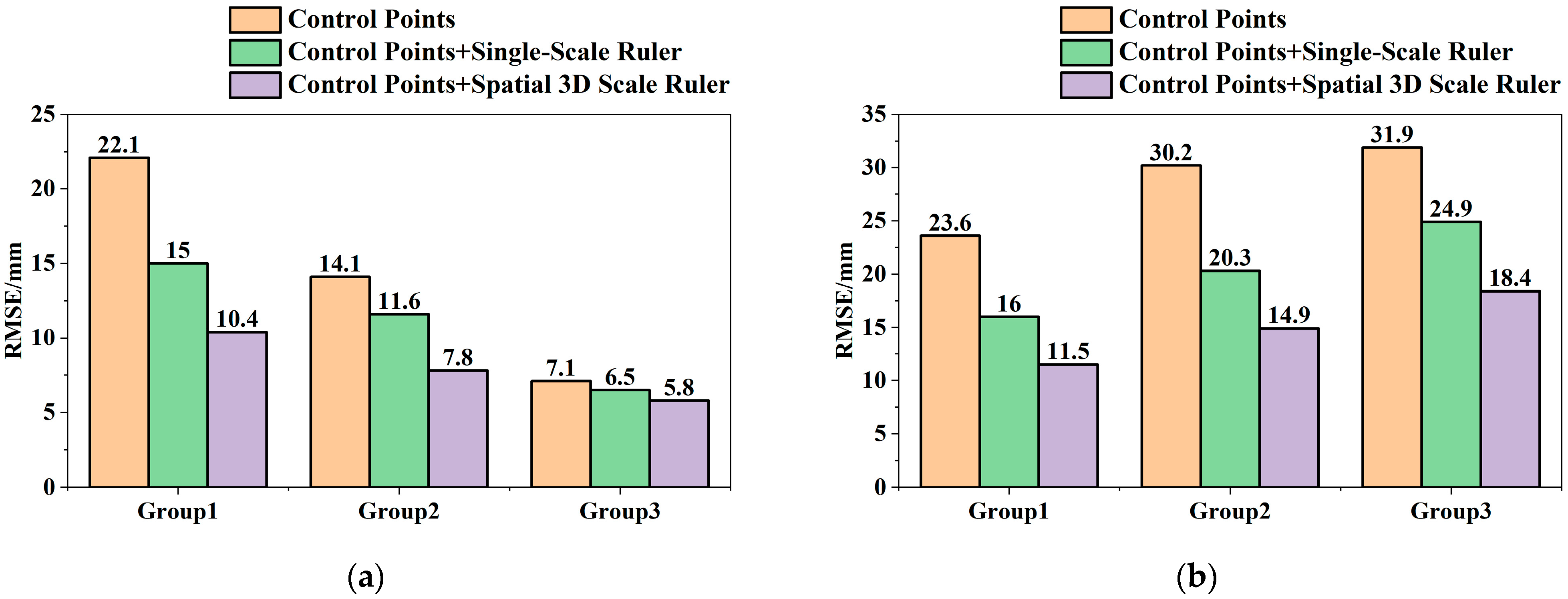
| Group 1 | 32.1% | 32.2% | 52.9% | 51.3% |
| Group 2 | 17.7% | 32.8% | 44.7% | 50.7% |
| Group 3 | 8.5% | 21.9% | 18.3% | 42.3% |
| Average | 19.4% | 29.0% | 38.6% | 48.1% |
| Monitoring Direction | Method | (%) | RMSE (%) |
|---|---|---|---|
| Horizontal | Control points + single scale Ruler | 11.8 | 21.7 |
| Control points + spatial 3D scale Ruler | 17.6 | 41.4 | |
| Vertical | Control points + single scale Ruler | 6.13 | 29.4 |
| Control points + spatial 3D scale Ruler | 5.03 | 48.3 |
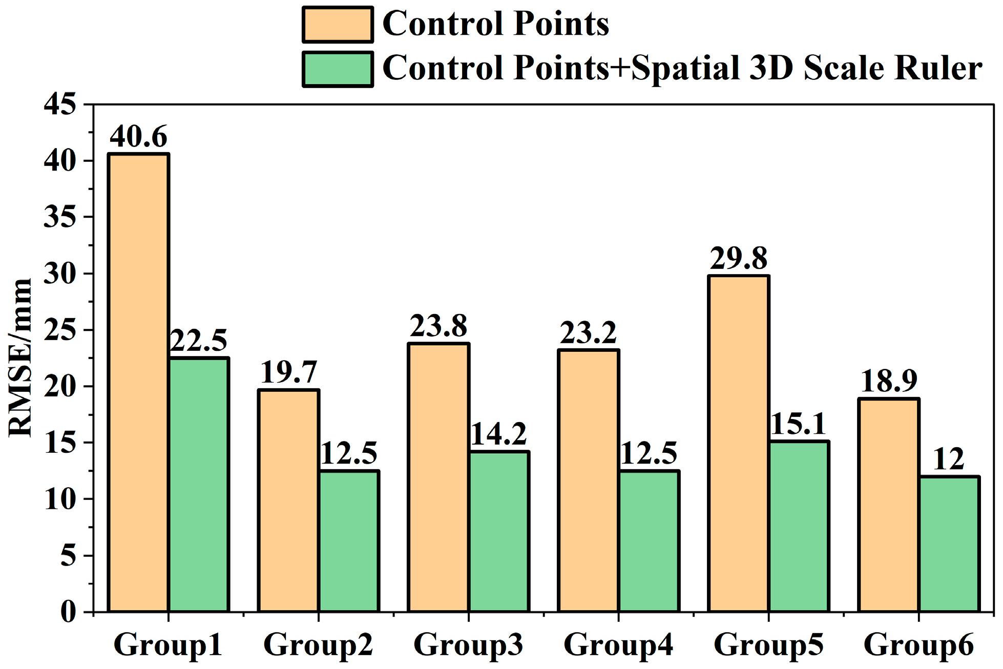
| Monitoring Group | Accuracy Improvement Rate (%) |
|---|---|
| Group 1 | 44.7 |
| Group 2 | 36.6 |
| Group 3 | 40.3 |
| Group 4 | 45.9 |
| Group 5 | 49.3 |
| Group 6 | 36.8 |
| Average | 42.3 |
Disclaimer/Publisher’s Note: The statements, opinions and data contained in all publications are solely those of the individual author(s) and contributor(s) and not of MDPI and/or the editor(s). MDPI and/or the editor(s) disclaim responsibility for any injury to people or property resulting from any ideas, methods, instructions or products referred to in the content. |
© 2025 by the authors. Licensee MDPI, Basel, Switzerland. This article is an open access article distributed under the terms and conditions of the Creative Commons Attribution (CC BY) license (https://creativecommons.org/licenses/by/4.0/).
Share and Cite
Liu, J.; Wu, J.; Dai, W.; Pan, D.; Zhou, M.; Xing, L.; Yu, Z. A UAV Vision-Based Deformation Monitoring Method with 3D Scale Constraints. Sensors 2025, 25, 7418. https://doi.org/10.3390/s25247418
Liu J, Wu J, Dai W, Pan D, Zhou M, Xing L, Yu Z. A UAV Vision-Based Deformation Monitoring Method with 3D Scale Constraints. Sensors. 2025; 25(24):7418. https://doi.org/10.3390/s25247418
Chicago/Turabian StyleLiu, Jianlin, Jun Wu, Wujiao Dai, Deyong Pan, Min Zhou, Lei Xing, and Zhiwu Yu. 2025. "A UAV Vision-Based Deformation Monitoring Method with 3D Scale Constraints" Sensors 25, no. 24: 7418. https://doi.org/10.3390/s25247418
APA StyleLiu, J., Wu, J., Dai, W., Pan, D., Zhou, M., Xing, L., & Yu, Z. (2025). A UAV Vision-Based Deformation Monitoring Method with 3D Scale Constraints. Sensors, 25(24), 7418. https://doi.org/10.3390/s25247418