Design of a Millimeter-Wave MIMO Antenna Array for 5G Communication Terminals

 ,
,  ,
,  and
and 
Abstract
:1. Introduction
2. Antenna Geometry
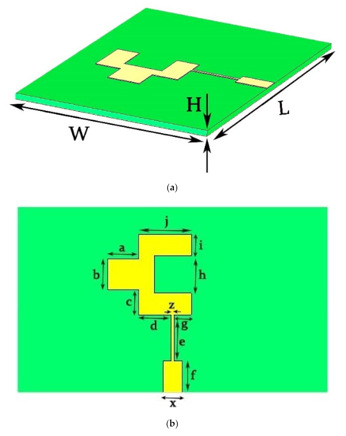
2.1. Single Element
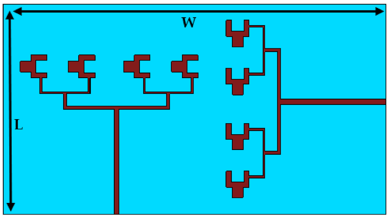
2.2. Multiple Element Antenna Arrays
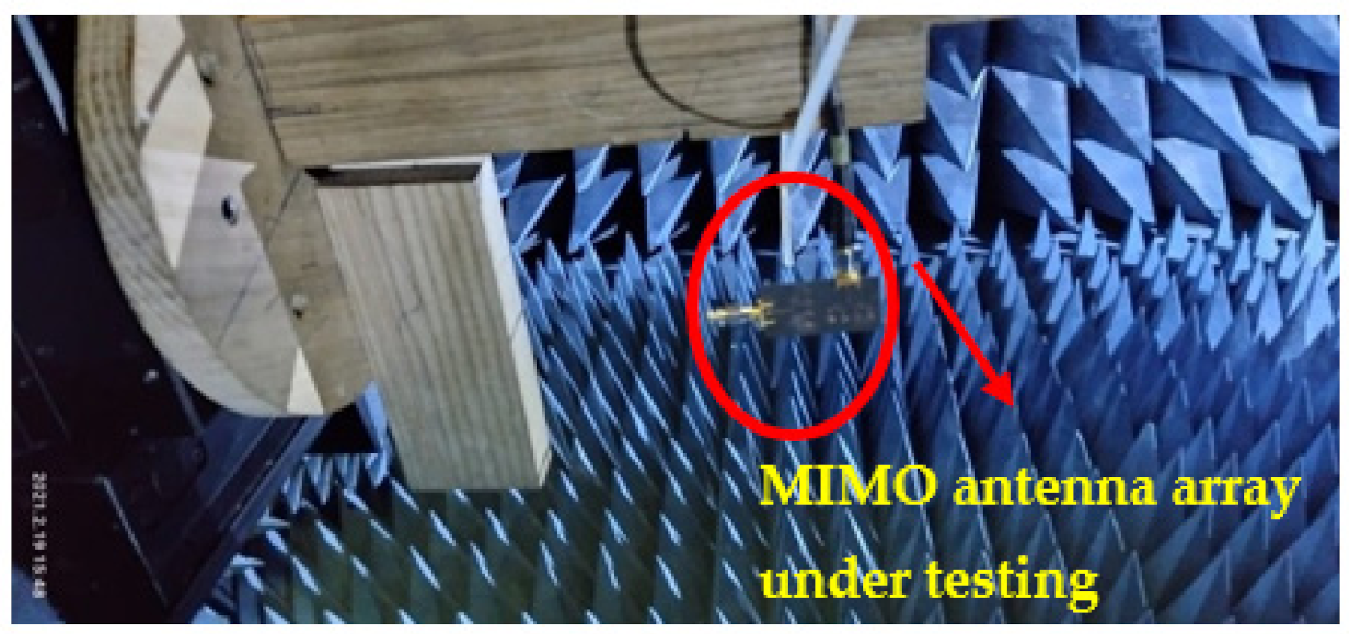
2.3. MIMO Configuration
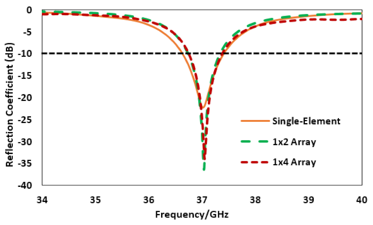
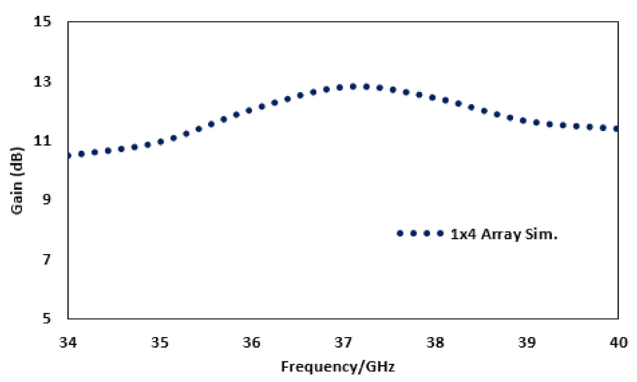
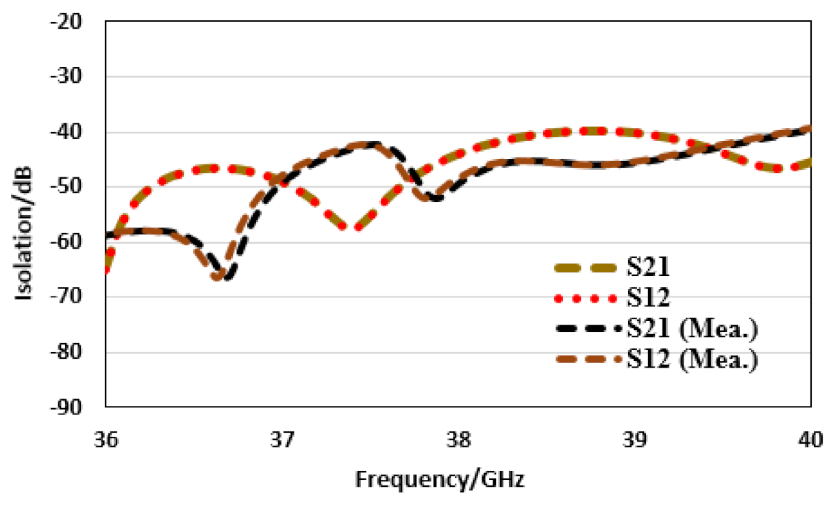
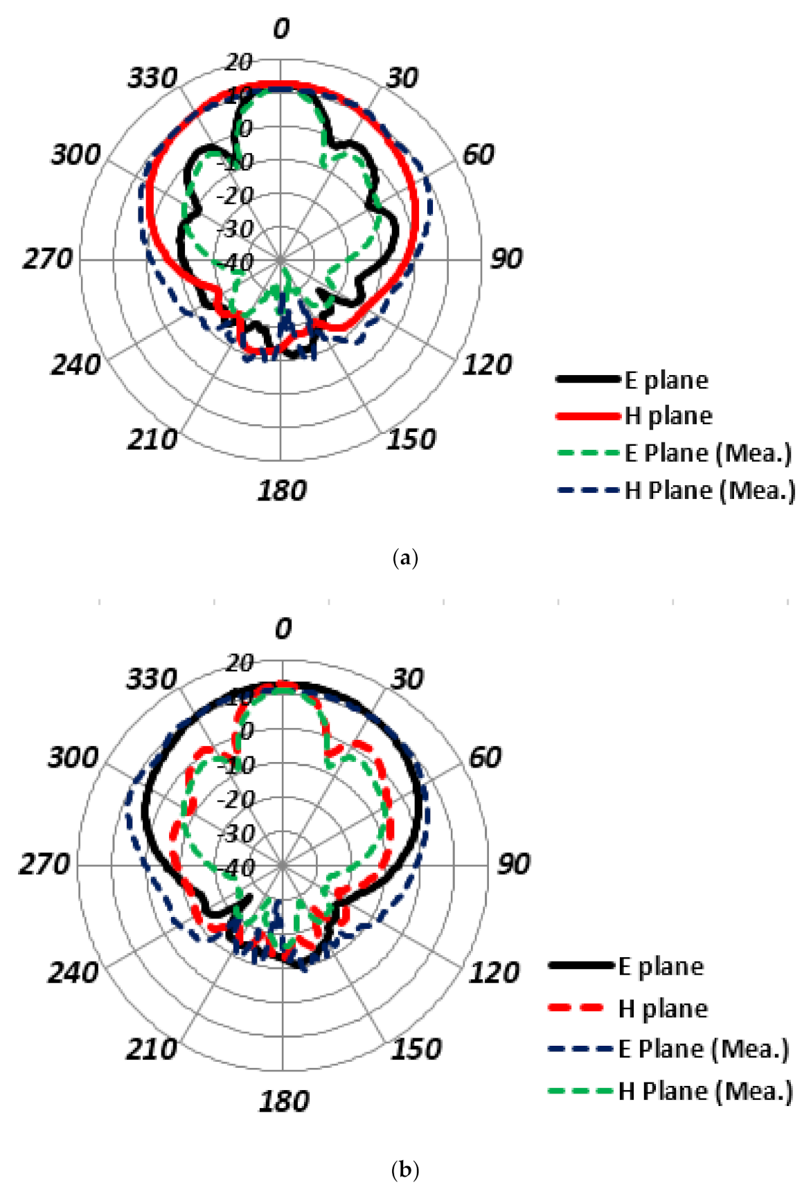
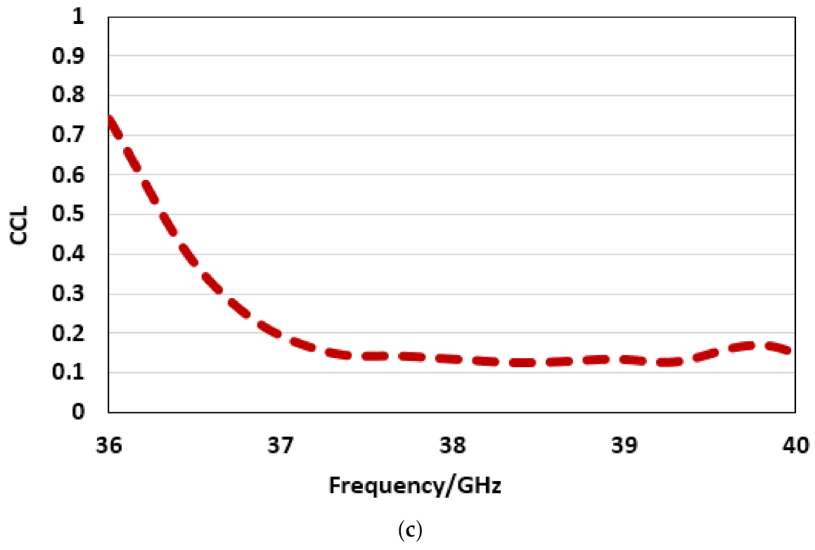
3. Results and Discussion
4. Conclusions
Author Contributions
Funding
Institutional Review Board Statement
Informed Consent Statement
Data Availability Statement
Conflicts of Interest
References
- Storck, C.R.; Duarte-Figueiredo, F. A survey of 5G technology evolution, standards, and infrastructure associated with vehicle-to-everything communications by internet of vehicles. IEEE Access 2020, 8, 117593–117614. [Google Scholar] [CrossRef]
- Barreto, A.N.; Faria, B.; Almeida, E.; Rodriguez, I.; Lauridsen, M.; Amorim, R.; Vieira, R. 5G—Wireless Communications for 2020. J. Commun. Inf. Syst. 2016, 31, 146–163. [Google Scholar] [CrossRef] [Green Version]
- Patnaik, P.; Sarkar, D.; Saha, C. A multi-band 5G antenna for Smart phones operating at Sub-6 GHz frequencies. In Proceedings of the IEEE International Symposium on Antennas & Propagation (APSYM), Montreal, QC, Canada, 4–11 July 2020; pp. 32–35. [Google Scholar]
- Nam, H.J.; Lim, S.; Yoon, Y.J.; Kim, H. Tunable triple-band antenna for Sub-6 GHz 5G mobile phone. In Proceedings of the IEEE International Symposium on Antennas and Propagation and North American Radio Science Meeting, Montreal, QC, Canada, 5–10 July 2020; pp. 1455–1456. [Google Scholar]
- Jiang, J.; Li, Y. A wideband kanji patch antenna for 5G Sub-6-GHz applications. In Proceedings of the IEEE 13th UK-Europe-China Workshop on Millimetre-Waves and Terahertz Technologies (UCMMT), Tianjin, China, 29–31 August 2020; pp. 1–2. [Google Scholar]
- Sehrai, D.A.; Abdullah, M.; Altaf, A.; Kiani, S.H.; Muhammad, F.; Tufail, M.; Irfan, M.; Glowacz, A.; Rahman, S. A novel high gain wideband MIMO antenna for 5 G millimeter wave applications. Electronics 2020, 9, 1031. [Google Scholar] [CrossRef]
- Mao, C.; Gao, S.; Wang, Y. Broadband high-gain beam-scanning antenna array for millimeter-wave applications. IEEE Trans. Antennas Propag. 2017, 65, 4864–4868. [Google Scholar] [CrossRef]
- Zhu, J.; Chu, C.; Deng, L.; Zhang, C.; Yang, Y.; Li, S. mm-wave high gain cavity-backed aperture-coupled patch antenna array. IEEE Access 2018, 6, 44050–44058. [Google Scholar] [CrossRef]
- Raheel, K.; Altaf, A.; Waheed, A.; Kiani, S.H.; Sehrai, D.A.; Tubbal, F.; Raad, R. E-shaped H-slotted dual band mmWave antenna for 5G technology. Electronics 2021, 10, 1019. [Google Scholar] [CrossRef]
- Di Paola, C.; Zhao, K.; Zhang, S.; Pedersen, G.F. SIW multibeam antenna array at 30 GHz for 5G mobile devices. IEEE Access 2019, 7, 73157–73164. [Google Scholar] [CrossRef]
- Yang, S.J.; Pan, Y.M.; Shi, L.; Zhang, X.Y. Millimeter-wave dual-polarized filtering antenna for 5G application. IEEE Trans. Antennas Propag. 2020, 68, 5114–5121. [Google Scholar] [CrossRef]
- Ali, M.; Muñoz, L.E.G.; Carpintero, G.; Nellen, S.; Globisch, B. Millimetre-wave photonic emitter integrating a PIN-PD and planar high gain antenna. In Proceedings of the IEEE Third International Workshop on Mobile Terahertz Systems (IWMTS), Essen, Germany, 2–3 July 2020; pp. 1–5. [Google Scholar]
- Johnson, M.; Dascurcu, J.; Zhan, K.; Galioglu, A.; Adepu, N.; Jain, S.; Krishnaswamy, H.; Natarajan, A.S. Code-domain multiplexing for shared IF/LO interfaces in millimeter-wave MIMO arrays. IEEE J. Solid-State Circuits 2020, 55, 1270–1281. [Google Scholar] [CrossRef]
- Zhang, J.; Huang, Y.; Wang, J.; Schober, R.; Yang, L. Power-efficient beam designs for millimeter wave communication systems. IEEE Trans. Wirel. Commun. 2020, 19, 1265–1279. [Google Scholar] [CrossRef]
- Xu, H.; Yu, J.; Zhu, S. Ping-pong optimization of user selection and beam allocation for millimeter wave communications. IEEE Access 2019, 7, 133178–133189. [Google Scholar] [CrossRef]
- Zhao, X.; Yeo, S.P.; Ong, L.O. Decoupling of inverted-F antennas with high-order modes of ground plane for 5G mobile MIMO platform. IEEE Trans. Antennas Propag. 2017, 66, 4485–4495. [Google Scholar] [CrossRef]
- Li, M.Y.; Xu, Z.Q.; Ban, Y.L.; Sim, C.Y.D.; Yu, Z.F. Eight-port orthogonally dual-polarized MIMO antenna using loop structures for 5G smartphone. IET Microw. Antennas Propag. 2017, 11, 1810–1816. [Google Scholar] [CrossRef]
- Li, M.Y.; Ban, Y.L.; Xu, Z.Q.; Guo, J.; Yu, Z.F. Tri-polarized 12-Antenna MIMO array for future 5G smartphone applications. IEEE Access 2017, 6, 6160–6170. [Google Scholar] [CrossRef]
- Jiang, W.; Cui, Y.; Liu, B.; Hu, W.; Xi, Y. A dual-band MIMO antenna with enhanced isolation for 5G smartphone applications. IEEE Access 2019, 7, 112554–112563. [Google Scholar] [CrossRef]
- Li, H.; Tsiaras, A.; Lau, B.K. Analysis and estimation of MIMO-SAR for multi-antenna mobile handsets. IEEE Trans. Antennas Propag. 2017, 65, 1522–1527. [Google Scholar] [CrossRef] [Green Version]
- Li, M.Y.; Li, C.; Ban, Y.L.; Kang, K. Multiple antennas for future 4G/5G smartphone applications. In Proceedings of the IEEE MTT-S International Microwave Workshop Series on Advanced Materials and Processes for RF and THz Applications (IMWS-AMP), Chengdu, China, 20–22 July 2016. [Google Scholar]
- Corchia, L.; Monti, G.; Tarricone, L. Wearable antennas: Nontextile versus fully textile solutions. IEEE Antennas Propag. 2019, 61, 71–83. [Google Scholar] [CrossRef]
- Wang, M.; Ma, H.F.; Zhang, H.C.; Tang, W.X.; Zhang, X.R.; Cui, T.J. Frequency-fixed beamscanning leaky-wave antenna using electronically controllable corrugated microstrip line. IEEE Trans. Antennas Propag. 2018, 66, 4449–4457. [Google Scholar] [CrossRef]
- Wang, J.; Lu, W.; Liu, Z.; Zhang, A.; Chen, H. Graphene-based microwave antennas with reconfigurable pattern. IEEE Trans. Antennas Propag. 2019, 68, 2504–2510. [Google Scholar] [CrossRef]
- Tang, L.; Zhang, J.; Tang, Y.; Kong, J.; Liu, T.; Gu, J. Polymer matrix wave-transparent composites: A review. J. Mater. Sci. Technol. 2021, 75, 225–251. [Google Scholar] [CrossRef]
- Dumitru, A.I.; Velciu, G.; Pintea, J.; Patroi, D.; Marinescu, V.; Clicinschi, F.; Matekovits, L.; Peter, I. Investigations on the doping effects on the properties of piezoelectric ceramics. Adv. Mater. Res. 2020, 1158, 105–114. [Google Scholar] [CrossRef]
- Park, T.H.; Kim, S.M.; Oh, M.C. Polymeric tunable wavelength filter with two-stage cascaded tilted Bragg gratings. Opt. Express 2020, 28, 10145–10152. [Google Scholar] [CrossRef] [PubMed]
- Sharaf, M.H.; Zaki, A.I.; Hamad, R.K.; Omar, M.M.M. A novel dual-band (38/60 GHz) patch antenna for 5G mobile handsets. Sensors 2020, 20, 2541. [Google Scholar] [CrossRef] [PubMed]
- Khan, J.; Sehrai, D.A.; Ali, U. Design of dual band 5G antenna array with SAR analysis for future mobile handsets. J. Electr. Eng. Technol. 2019, 14, 809–816. [Google Scholar] [CrossRef]
- Peng, M.; Zhao, A. High performance 5G millimeter-wave antenna array for 37–40 GHz mobile application. In Proceedings of the IEEE International Workshop on Antenna Technology (iWAT), Bucharest, Romania, 25–28 February 2018; pp. 1–4. [Google Scholar]
- Park, J.; Choi, D.; Hong, W. 37–39 GHz vertically-polarized end-fire 5G antenna array featuring electrically small profile. In Proceedings of the IEEE International Symposium on Antennas and Propagation & USNC/URSI National Radio Science Meeting, Marina Bay Sands, Singapore, 10–16 July 2018; pp. 637–638. [Google Scholar]
- Khan, J.; Sehrai, D.A.; Khan, M.A.; Khan, H.A.; Ahmad, S.; Ahmad, S.; Ali, A.; Arif, A.; Memon, A.A.; Khan, S. Design and performance comparison of rotated Y-shaped antenna using different metamaterial surfaces for 5G mobile devices. Comput. Mater. Contin. 2019, 2, 409–420. [Google Scholar] [CrossRef]
- Nosrati, M.; Tavassolian, N. A single feed dual-band, linearly/circularly polarized cross-slot millimeter-wave antenna for future 5G networks. In Proceedings of the IEEE International Symposium on Antennas and Propagation & USNC/URSI National Radio Science Meeting, Denver, CO, USA, 10–15 July 2017; pp. 2467–2468. [Google Scholar]
- Sehrai, D.A.; Asif, M.; Shoaib, N.; Ibrar, M.; Jan, S.; Alibakhshikenari, M.; Lalbakhsh, A.; Limiti, E. Compact Quad-Element High-Isolation Wideband MIMO Antenna for mm-Wave Applications. Electronics 2021, 10, 1300. [Google Scholar] [CrossRef]
- Ballanis, C.A. Antenna Theory Analysis and Design; John Willey and Son’s Inc.: New York, NY, USA, 2016. [Google Scholar]
- Ojaroudiparchin, N.; Shen, M.; Pedersen, G.F. Beam-steerable microstrip-fed bow-tie antenna array for fifth generation cellular communications. In Proceedings of the IEEE 10th European Conference on Antennas and Propagation (EuCAP), Davos, Switzerland, 10–15 April 2016; pp. 1–5. [Google Scholar]
- Kamal, M.M.; Yang, S.; Kiani, S.H.; Sehrai, D.A.; Alibakhshikenari, M.; Abdullah, M.; Falcone, F.; Limiti, E.; Munir, M. A Novel Hook-Shaped Antenna Operating at 28 GHz for Future 5G mmwave Applications. Electronics 2021, 10, 673. [Google Scholar] [CrossRef]
- Ullah, U.; Al-Hasan, M.; Koziel, S.; Mabrouk, I.B. Series-slot-fed circularly polarized multiple-input–multiple-output antenna array enabling circular polarization diversity for 5G 28 GHz indoor applications. IEEE Trans. Antennas Propag. 2021, 69, 5607–5616. [Google Scholar] [CrossRef]
- Hussain, N.; Jeong, M.; Abbas, A.; Kim, N. Metasurface-based single-layer wideband circularly polarized MIMO antenna for 5G millimeter-wave systems. IEEE Access 2020, 8, 130293–130304. [Google Scholar] [CrossRef]
- Dicandia, F.A.; Genovesi, S.; Monorchio, A. Analysis of the performance enhancement of MIMO systems employing circular polarization. IEEE Trans. Antennas Propag. 2017, 65, 4824–4835. [Google Scholar] [CrossRef]
- Sun, W.; Li, Y.; Chang, L.; Li, H.; Qin, X.; Wang, H. Dual-band dual-polarized microstrip antenna array using double-layer gridded patches for 5G millimeter-wave applications. IEEE Trans. Antennas Propag. 2021, 69, 6489–6499. [Google Scholar] [CrossRef]
- Li, H.; Li, Y.; Chang, L.; Sun, W.; Qin, X.; Wang, H. A wideband dual-polarized endfire antenna array with overlapped apertures and small clearance for 5G millimeter-wave applications. IEEE Trans. Antennas Propag. 2020, 69, 815–824. [Google Scholar] [CrossRef]


| Parameter | L | W | H | a | b | c | d | e |
|---|---|---|---|---|---|---|---|---|
| Value (mm) | 10 | 6 | 0.254 | 1 | 1 | 0.8 | 1.05 | 1.5 |
| Parameter | f | G | i | j | k | s | w | z |
| Value (mm) | 1 | 0.55 | 0.7 | 1.7 | 1.22 | 1.21 | 0.62 | 0.1 |
| Parameter | p | q | z1 | z2 | z3 | z8 |
|---|---|---|---|---|---|---|
| Value (mm) | 20 | 8 | 4.56 | 1.1 | 90 | 1.6 |
| Parameter | z4 | z5 | z6 | z7 | gp | - |
| Value (mm) | 1.4 | 0.27 | 0.2 | 0.1 | 1.9 |
Publisher’s Note: MDPI stays neutral with regard to jurisdictional claims in published maps and institutional affiliations. |
© 2022 by the authors. Licensee MDPI, Basel, Switzerland. This article is an open access article distributed under the terms and conditions of the Creative Commons Attribution (CC BY) license (https://creativecommons.org/licenses/by/4.0/).
Share and Cite
Khan, J.; Ullah, S.; Ali, U.; Tahir, F.A.; Peter, I.; Matekovits, L. Design of a Millimeter-Wave MIMO Antenna Array for 5G Communication Terminals. Sensors 2022, 22, 2768. https://doi.org/10.3390/s22072768
Khan J, Ullah S, Ali U, Tahir FA, Peter I, Matekovits L. Design of a Millimeter-Wave MIMO Antenna Array for 5G Communication Terminals. Sensors. 2022; 22(7):2768. https://doi.org/10.3390/s22072768
Chicago/Turabian StyleKhan, Jalal, Sadiq Ullah, Usman Ali, Farooq Ahmad Tahir, Ildiko Peter, and Ladislau Matekovits. 2022. "Design of a Millimeter-Wave MIMO Antenna Array for 5G Communication Terminals" Sensors 22, no. 7: 2768. https://doi.org/10.3390/s22072768
APA StyleKhan, J., Ullah, S., Ali, U., Tahir, F. A., Peter, I., & Matekovits, L. (2022). Design of a Millimeter-Wave MIMO Antenna Array for 5G Communication Terminals. Sensors, 22(7), 2768. https://doi.org/10.3390/s22072768