
An Intelligent Approach for Cloud-Fog-Edge Computing SDN-VANETs Based on Fuzzy Logic: Effect of Different Parameters on Coordination and Management of Resources

 ,
,  , , , and
Abstract
:1. Introduction
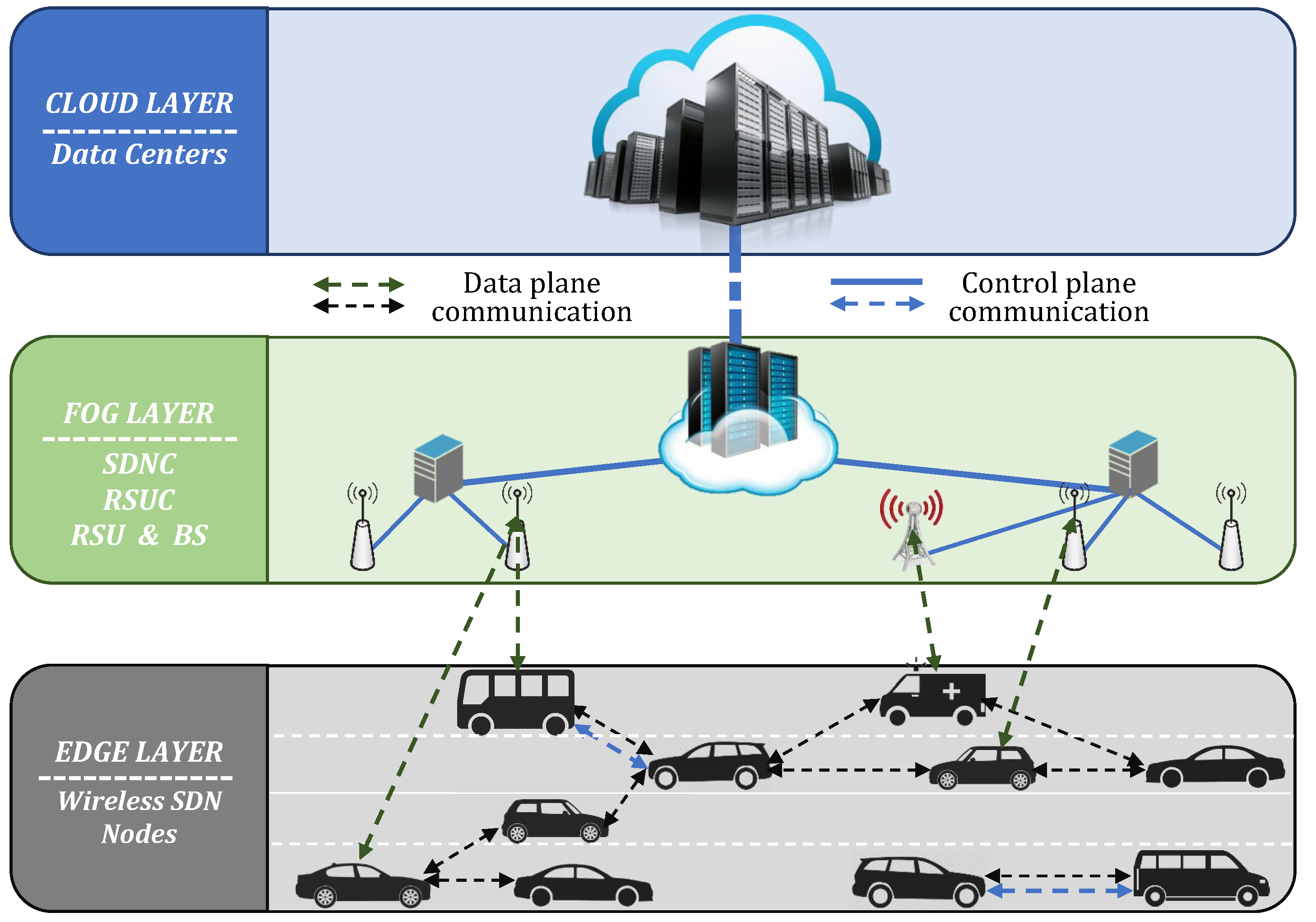
- The paper presents an integrated system, called Integrated Fuzzy-based System for Coordination and Management of Resources (IFS-CMR), which, different from existing approaches, makes a decision following a bottom-up approach in a cloud-fog-edge architecture.
- IFS-CMR considers the condition of the network created between vehicles, such as the Quality of Service (QoS) in the network and the unused amount of resources, together with the application requirements, to select the best resources for a particular situation.
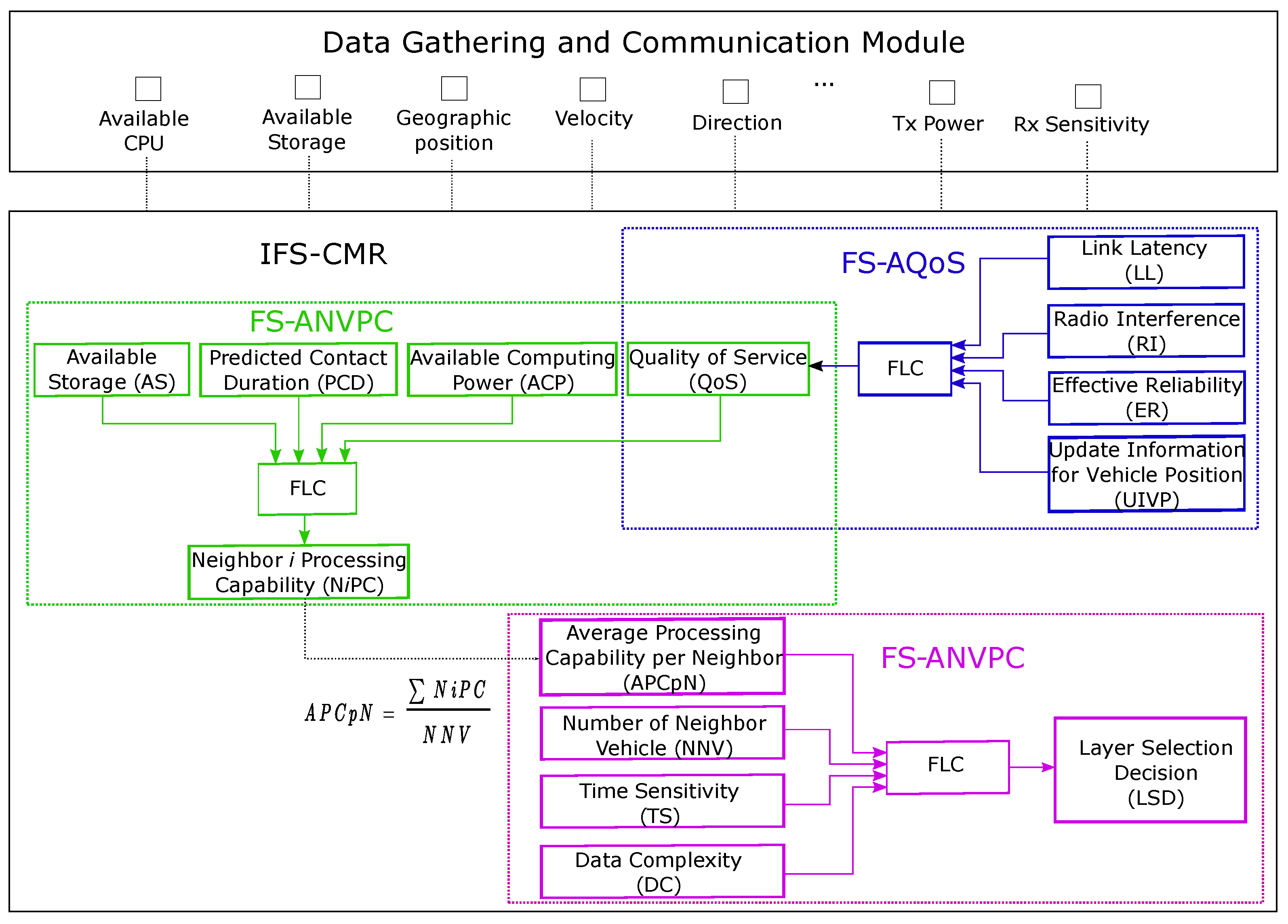
- IFS-CMR is composed of three subsystems, namely Fuzzy-based System for Assessment of QoS (FS-AQoS), Fuzzy-based System for Assessment of Neighbor Vehicle Processing Capability (FS-ANVPC), and Fuzzy-based System for Cloud-Fog-Edge Layer Selection (FS-CFELS), each having a key role in the proposed approach.
- The feasibility of the proposed architecture in coordinating and managing the available VANETs resources is demonstrated by the results of extensive simulations.
2. Background Overview
2.1. Internet of Things
2.2. Cloud, Fog, and Edge Computing
2.3. Software Defined Networking
2.4. Vehicular Ad Hoc Networks
2.5. Related Works
3. Proposed Architecture
3.1. Data Gathering and Communication Module
3.2. IFS-CMR Parameters
3.3. Description of IFS-CMR Subsystems
4. Simulation Results
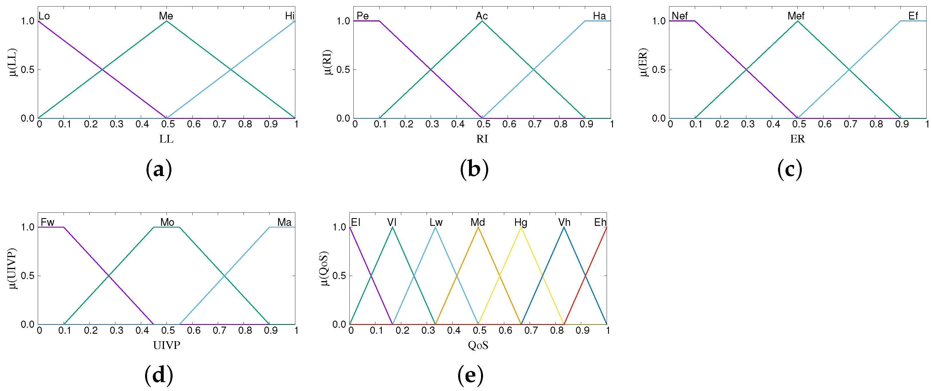
4.1. Results of FS-AQoS
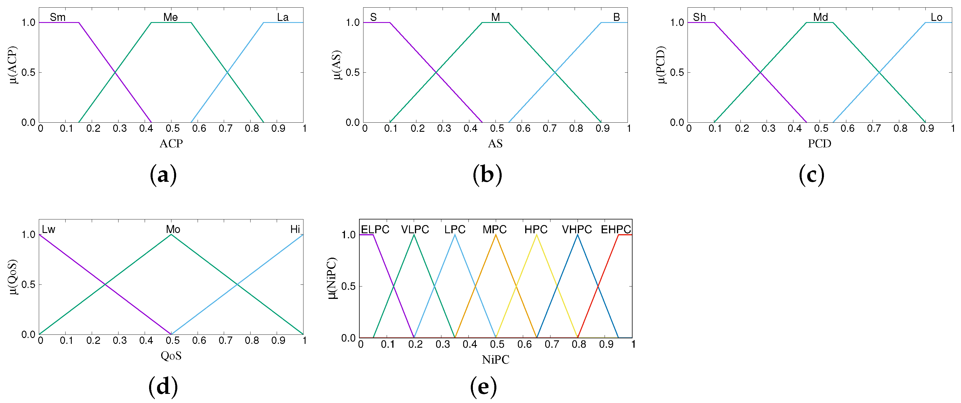
4.2. Results of FS-ANVPC
4.3. Results of FS-CFELS
5. Conclusions
- Higher QoS values are achieved for a moderate number of beacon messages broadcasted, which increases the possibility of vehicles being categorized as potentially helpful neighbors.
- When a neighbor vehicle offers only a small amount of resources, it is considered less capable of helping, regardless of the quality of communication.
- In a dense environment, moderate complex data can be processed in the edge only if there are many potentially helpful neighbors in the vicinity.
- Time-sensitive applications are run either in edge or fog layer and never in the cloud.
- With the increase of data complexity less data is processed in the edge layer even if vehicles stay connected to the same potentially helpful neighbors for a long time.
Author Contributions
Funding
Data Availability Statement
Conflicts of Interest
References
- World Health Organization. Global Status Report on Road Safety 2018: Summary; (WHO/NMH/NVI/18.20). Licence: CC BY-NC-SA 3.0 IGO); World Health Organization: Geneva, Switzerland, 2018. [Google Scholar]
- Rolison, J.J.; Regev, S.; Moutari, S.; Feeney, A. What are the factors that contribute to road accidents? An assessment of law enforcement views, ordinary drivers’ opinions, and road accident records. Accid. Anal. Prev. 2018, 115, 11–24. [Google Scholar] [CrossRef] [PubMed]
- Colagrande, S. A methodology for the characterization of urban road safety through accident data analysis. Transp. Res. Procedia 2022, 60, 504–511. [Google Scholar] [CrossRef]
- Fang Wu, G.; Jia Liu, F.; Liang Dong, G. Analysis of the Influencing Factors of Road Environment in Road Traffic Accidents. In Proceedings of the 2020 4th Annual International Conference on Data Science and Business Analytics (ICDSBA), Changsha, China, 5–6 September 2020; pp. 83–85. [Google Scholar] [CrossRef]
- Lu, N.; Cheng, N.; Zhang, N.; Shen, X.; Mark, J.W. Connected Vehicles: Solutions and Challenges. IEEE Internet Things J. 2014, 1, 289–299. [Google Scholar] [CrossRef]
- Seo, H.; Lee, K.D.; Yasukawa, S.; Peng, Y.; Sartori, P. LTE evolution for vehicle-to-everything services. IEEE Commun. Mag. 2016, 54, 22–28. [Google Scholar] [CrossRef]
- Raza, S.; Wang, S.; Ahmed, M.; Anwar, M.R. A Survey on Vehicular Edge Computing: Architecture, Applications, Technical Issues, and Future Directions. Wirel. Commun. Mob. Comput. 2019, 2019, 3159762. [Google Scholar] [CrossRef]
- Aung, N.; Zhang, W.; Dhelim, S.; Ai, Y. Accident Prediction System Based on Hidden Markov Model for Vehicular Ad-Hoc Network in Urban Environments. Information 2018, 9, 311. [Google Scholar] [CrossRef] [Green Version]
- Luan, T.H.; Cai, L.X.; Chen, J.; Shen, X.S.; Bai, F. Engineering a Distributed Infrastructure for Large-Scale Cost-Effective Content Dissemination over Urban Vehicular Networks. IEEE Trans. Veh. Technol. 2014, 63, 1419–1435. [Google Scholar] [CrossRef]
- Shrestha, R.; Bajracharya, R.; Nam, S.Y. Challenges of Future VANET and Cloud-Based Approaches. Wirel. Commun. Mob. Comput. 2018, 2018. [Google Scholar] [CrossRef]
- Karagiannis, G.; Altintas, O.; Ekici, E.; Heijenk, G.; Jarupan, B.; Lin, K.; Weil, T. Vehicular networking: A survey and tutorial on requirements, architectures, challenges, standards and solutions. IEEE Commun. Surv. Tutorials 2011, 13, 584–616. [Google Scholar] [CrossRef]
- He, Y.; Liu, Z.; Zhou, X.; Zhong, B. Analysis of Urban Traffic Accidents Features and Correlation with Traffic Congestion in Large-Scale Construction District. In Proceedings of the 2017 International Conference on Smart Grid and Electrical Automation (ICSGEA), Changsha, China, 27–28 May 2017; pp. 641–644. [Google Scholar] [CrossRef]
- Taha, A.E.; AbuAli, N. Route Planning Considerations for Autonomous Vehicles. IEEE Commun. Mag. 2018, 56, 78–84. [Google Scholar] [CrossRef]
- de Souza, A.M.; Braun, T.; Botega, L.C.; Cabral, R.; Garcia, I.C.; Villas, L.A. Better safe than sorry: A vehicular traffic re-routing based on traffic conditions and public safety issues. J. Internet Serv. Appl. 2019, 10, 17. [Google Scholar] [CrossRef] [Green Version]
- Jurgen, R. V2V/V2I Communications for Improved Road Safety and Efficiency; SAE International: Warrendale, PA, USA, 2012. [Google Scholar]
- Wang, S.; Huang, A.; Zhang, T. Performance Evaluation of IEEE 802.15.4 for V2V Communication in VANET. In Proceedings of the 2013 International Conference on Computational and Information Sciences, Shiyang, China, 21–23 June 2013; pp. 1603–1606. [Google Scholar] [CrossRef]
- Prayitno, A.; Nilkhamhang, I. V2V Network Topologies for Vehicle Platoons with Cooperative State Variable Feedback Control. In Proceedings of the 2021 Second International Symposium on Instrumentation, Control, Artificial Intelligence, and Robotics (ICA-SYMP), Bangkok, Thailand, 20–22 January 2021; pp. 1–4. [Google Scholar] [CrossRef]
- Lee, M.; Atkison, T. VANET applications: Past, present, and future. Veh. Commun. 2021, 28, 100310. [Google Scholar] [CrossRef]
- Lottermann, C.; Botsov, M.; Fertl, P.; Müllner, R.; Araniti, G.; Campolo, C.; Condoluci, M.; Iera, A.; Molinaro, A. LTE for Vehicular Communications. In Vehicular ad hoc Networks: Standards, Solutions, and Research; Springer International Publishing: Cham, Switzerland, 2015; pp. 457–501. [Google Scholar] [CrossRef]
- Hartenstein, H.; Laberteaux, K. Introduction. In VANET Vehicular Applications and Inter-Networking Technologies; John Wiley & Sons: Hoboken, NJ, USA, 2010; pp. 1–19. [Google Scholar] [CrossRef]
- Gyawali, S.; Xu, S.; Qian, Y.; Hu, R.Q. Challenges and Solutions for Cellular-Based V2X Communications. IEEE Commun. Surv. Tutorials 2021, 23, 222–255. [Google Scholar] [CrossRef]
- Gasmi, R.; Aliouat, M. Vehicular Ad Hoc NETworks versus Internet of Vehicles—A Comparative View. In Proceedings of the 2019 International Conference on Networking and Advanced Systems (ICNAS), Annaba, Algeria, 26–27 June 2019; pp. 1–6. [Google Scholar] [CrossRef]
- Cheng, J.; Yuan, G.; Zhou, M.; Gao, S.; Liu, C.; Duan, H.; Zeng, Q. Accessibility Analysis and Modeling for IoV in an Urban Scene. IEEE Trans. Veh. Technol. 2020, 69, 4246–4256. [Google Scholar] [CrossRef]
- Hbaieb, A.; Ayed, S.; Chaari, L. A survey of trust management in the Internet of Vehicles. Comput. Netw. 2022, 203, 108558. [Google Scholar] [CrossRef]
- Sakiz, F.; Sen, S. A survey of attacks and detection mechanisms on intelligent transportation systems: VANETs and IoV. Ad Hoc Netw. 2017, 61, 33–50. [Google Scholar] [CrossRef]
- Yang, F.; Wang, S.; Li, J.; Liu, Z.; Sun, Q. An overview of Internet of Vehicles. China Commun. 2014, 11, 1–15. [Google Scholar] [CrossRef]
- Al-Heety, O.S.; Zakaria, Z.; Ismail, M.; Shakir, M.M.; Alani, S.; Alsariera, H. A Comprehensive Survey: Benefits, Services, Recent Works, Challenges, Security, and Use Cases for SDN-VANET. IEEE Access 2020, 8, 91028–91047. [Google Scholar] [CrossRef]
- Fadhil, J.A.; Sarhan, Q.I. Internet of Vehicles (IoV): A Survey of Challenges and Solutions. In Proceedings of the 2020 21st International Arab Conference on Information Technology (ACIT), Giza, Egypt, 28–30 November 2020; pp. 1–10. [Google Scholar] [CrossRef]
- Yousefpour, A.; Fung, C.; Nguyen, T.; Kadiyala, K.; Jalali, F.; Niakanlahiji, A.; Kong, J.; Jue, J.P. All one needs to know about fog computing and related edge computing paradigms: A complete survey. J. Syst. Archit. 2019, 98, 289–330. [Google Scholar] [CrossRef]
- Paranjothi, A.; Tanik, U.; Wang, Y.; Khan, M.S. Hybrid-Vehfog: A robust approach for reliable dissemination of critical messages in connected vehicles. Trans. Emerg. Telecommun. Technol. 2019, 30, e3595. [Google Scholar] [CrossRef] [Green Version]
- Bonomi, F.; Milito, R.; Zhu, J.; Addepalli, S. Fog Computing and Its Role in the Internet of Things. In Proceedings of the First Edition of the MCC Workshop on Mobile Cloud Computing (MCC’12), Helsinki, Finland, 17 August 2012; pp. 13–16. [Google Scholar] [CrossRef]
- Nkenyereye, L.; Nkenyereye, L.; Islam, S.M.R.; Choi, Y.H.; Bilal, M.; Jang, J.W. Software-Defined Network-Based Vehicular Networks: A Position Paper on Their Modeling and Implementation. Sensors 2019, 19, 3788. [Google Scholar] [CrossRef] [PubMed] [Green Version]
- Bonomi, F.; Milito, R.; Natarajan, P.; Zhu, J. Fog Computing: A Platform for Internet of Things and Analytics. In Big Data and Internet of Things: A Roadmap for Smart Environments; Springer International Publishing: Cham, Switzerland, 2014; pp. 169–186. [Google Scholar] [CrossRef]
- Spinelli, F.; Mancuso, V. Toward Enabled Industrial Verticals in 5G: A Survey on MEC-Based Approaches to Provisioning and Flexibility. IEEE Commun. Surv. Tutor. 2021, 23, 596–630. [Google Scholar] [CrossRef]
- Dressler, F.; Pannu, G.S.; Hagenauer, F.; Gerla, M.; Higuchi, T.; Altintas, O. Virtual Edge Computing Using Vehicular Micro Clouds. In Proceedings of the 2019 International Conference on Computing, Networking and Communications (ICNC), Honolulu, HI, USA, 18–21 February 2019; pp. 537–541. [Google Scholar] [CrossRef]
- Miao, Z.; Li, C.; Zhu, L.; Han, X.; Wang, M.; Cai, X.; Liu, Z.; Xiong, L. On Resource Management in Vehicular Ad Hoc Networks: A Fuzzy Optimization Scheme. In Proceedings of the 2016 IEEE 83rd Vehicular Technology Conference (VTC Spring), Nanjing, China, 15–18 May 2016; pp. 1–5. [Google Scholar] [CrossRef]
- Li, J.; Natalino, C.; Van, D.P.; Wosinska, L.; Chen, J. Resource Management in Fog-Enhanced Radio Access Network to Support Real-Time Vehicular Services. In Proceedings of the 2017 IEEE 1st International Conference on Fog and Edge Computing (ICFEC), Madrid, Spain, 14–15 May 2017; pp. 68–74. [Google Scholar] [CrossRef]
- Khan, A.A.; Abolhasan, M.; Ni, W.; Lipman, J.; Jamalipour, A. A Hybrid-Fuzzy Logic Guided Genetic Algorithm (H-FLGA) Approach for Resource Optimization in 5G VANETs. IEEE Trans. Veh. Technol. 2019, 68, 6964–6974. [Google Scholar] [CrossRef]
- Mendiboure, L.; Chalouf, M.A.; Krief, F. Edge Computing Based Applications in Vehicular Environments: Comparative Study and Main Issues. J. Comput. Sci. Technol. 2019, 34, 869–886. [Google Scholar] [CrossRef]
- Mchergui, A.; Moulahi, T.; Nasri, S. QoS evaluation model based on intelligent fuzzy system for vehicular ad hoc networks. Computing 2020, 102, 2501–2520. [Google Scholar] [CrossRef]
- Bylykbashi, K.; Liu, Y.; Matsuo, K.; Ikeda, M.; Barolli, L.; Takizawa, M. A Fuzzy-Based System for Cloud-Fog-Edge Selection in VANETs. In Proceedings of the 2019 7th International Conference on Emerging Internetworking, Data & Web Technologies (EIDWT), Fujairah, UAE, 26–28 February 2019; pp. 1–12. [Google Scholar] [CrossRef]
- Qafzezi, E.; Bylykbashi, K.; Spaho, E.; Barolli, L. A New Fuzzy-Based Resource Management System for SDN-VANETs. Int. J. Mob. Comput. Multimed. Commun. (IJMCMC) 2019, 10, 1–12. [Google Scholar] [CrossRef]
- Qafzezi, E.; Bylykbashi, K.; Ikeda, M.; Matsuo, K.; Barolli, L. Coordination and Management of Cloud, Fog and Edge Resources in SDN-VANETs Using Fuzzy Logic: A Comparison Study for Two Fuzzy-based Systems. Internet Things 2020, 11. [Google Scholar] [CrossRef]
- Bylykbashi, K.; Qafzezi, E.; Ampririt, P.; Ikeda, M.; Matsuo, K.; Barolli, L. Performance Evaluation of an Integrated Fuzzy-Based Driving-Support System for Real-Time Risk Management in VANETs. Sensors 2020, 20, 6537. [Google Scholar] [CrossRef]
- Hartenstein, H.; Laberteaux, K. Cooperative Vehicular Safety Applications. In VANET Vehicular Applications and Inter-Networking Technologies; John Wiley & Sons: Hoboken, NJ, USA, 2010; pp. 21–48. [Google Scholar] [CrossRef]
- Ge, X.; Li, Z.; Li, S. 5G Software Defined Vehicular Networks. IEEE Commun. Mag. 2017, 55, 87–93. [Google Scholar] [CrossRef] [Green Version]
- Zadeh, L.A.; Kacprzyk, J. Fuzzy Logic for the Management of Uncertainty; John Wiley & Sons, Inc.: New York, NY, USA, 1992. [Google Scholar]
- Kandel, A. Fuzzy Expert Systems; CRC Press, Inc.: Boca Raton, FL, USA, 1992. [Google Scholar]
- McNeill, F.M.; Thro, E. Fuzzy Logic: A Practical Approach; Academic Press Professional, Inc.: San Diego, CA, USA, 1994. [Google Scholar]
- Zimmermann, H.J. Fuzzy control. In Fuzzy Set Theory and Its Applications; Springer: Berlin/Heidelberg, Germany, 1996; pp. 203–240. [Google Scholar]
- Munakata, T.; Jani, Y. Fuzzy systems: An overview. Commun. ACM 1994, 37, 69–77. [Google Scholar] [CrossRef]
- Klir, G.J.; Folger, T.A. Fuzzy Sets, Uncertainty, and Information; Prentice Hall: Upper Saddle River, NJ, USA, 1988. [Google Scholar]


| Parameters | Term Sets |
|---|---|
| Link Latency (LL) | Low (Lo), Medium (Me), High (Hi) |
| Radio Interference (RI) | Permissible (Pe), Acceptable (Ac), Harmful (Ha) |
| Effective Reliability (ER) | Not Effective (Nef), Medium Effective (Mef), Effective (Ef) |
| Update Info. for Vehicle Position (UIVP) | Few (Fw), Moderate (Mo), Many (Ma) |
| Quality of Service (QoS) | Extremely Low (El), Very Low (Vl), Low (Lw), Moderate (Md), |
| High (Hg), Very High (Vh), Extremely High (Eh) |
| Parameters | Term Sets |
|---|---|
| Available Computing Power (ACP) | Small (Sm), Medium (Me), Large (La) |
| Available Storage (AS) | Small (S), Medium (M), Big (B) |
| Predicted Contact Duration (PCD) | Short (Sh), Medium (Md), Long (Lo) |
| Quality of Service (QoS) | Low (Lw), Moderate (Mo), High (Hi) |
| Neighbor i Processing Capability (NiPC) | Extremely Low PC (ELPC), Very Low PC (VLPC), |
| Low PC (LPC), Moderate PC (MPC), High PC (HPC), | |
| Very High PC (VHPC), Extremely High PC (EHPC) |
| Parameters | Term Sets |
|---|---|
| Data Complexity (DC) | Low (Lo), Moderate (Mo), High (Hi) |
| Time Sensitivity (TS) | Low (Lw), Middle (Md), High (Hg) |
| Number of Neighboring Vehicles (NNV) | Sparse(Sp), Medium Density (Me), Dense (De) |
| Avg. PC per Neighbor Vehicle (APCpNV) | Low (L), Moderate (M), High (H) |
| Layer Selection Decision (LSD) | Decision Level 1 (DL1), DL2, DL3, DL4, DL5, DL6, DL7 |
| No | LL | RI | ER | UIVP | QoS | No | LL | RI | ER | UIVP | QoS | No | LL | RI | ER | UIVP | QoS |
|---|---|---|---|---|---|---|---|---|---|---|---|---|---|---|---|---|---|
| 1 | Lo | Pe | Nef | Fw | Hg | 28 | Me | Pe | Nef | Fw | Vl | 55 | Hi | Pe | Nef | Fw | El |
| 2 | Lo | Pe | Nef | Mo | Eh | 29 | Me | Pe | Nef | Mo | Lw | 56 | Hi | Pe | Nef | Mo | Vl |
| 3 | Lo | Pe | Nef | Ma | Hg | 30 | Me | Pe | Nef | Ma | Vl | 57 | Hi | Pe | Nef | Ma | El |
| 4 | Lo | Pe | Mef | Fw | Vh | 31 | Me | Pe | Mef | Fw | Lw | 58 | Hi | Pe | Mef | Fw | El |
| 5 | Lo | Pe | Mef | Mo | Eh | 32 | Me | Pe | Mef | Mo | Md | 59 | Hi | Pe | Mef | Mo | Lw |
| 6 | Lo | Pe | Mef | Ma | Vh | 33 | Me | Pe | Mef | Ma | Lw | 60 | Hi | Pe | Mef | Ma | El |
| 7 | Lo | Pe | Ef | Fw | Eh | 34 | Me | Pe | Ef | Fw | Md | 61 | Hi | Pe | Ef | Fw | Vl |
| 8 | Lo | Pe | Ef | Mo | Eh | 35 | Me | Pe | Ef | Mo | Hg | 62 | Hi | Pe | Ef | Mo | Md |
| 9 | Lo | Pe | Ef | Ma | Eh | 36 | Me | Pe | Ef | Ma | Md | 63 | Hi | Pe | Ef | Ma | Vl |
| 10 | Lo | Ac | Nef | Fw | Md | 37 | Me | Ac | Nef | Fw | El | 64 | Hi | Ac | Nef | Fw | El |
| 11 | Lo | Ac | Nef | Mo | Hg | 38 | Me | Ac | Nef | Mo | Lw | 65 | Hi | Ac | Nef | Mo | El |
| 12 | Lo | Ac | Nef | Ma | Md | 39 | Me | Ac | Nef | Ma | El | 66 | Hi | Ac | Nef | Ma | El |
| 13 | Lo | Ac | Mef | Fw | Hg | 40 | Me | Ac | Mef | Fw | Vl | 67 | Hi | Ac | Mef | Fw | El |
| 14 | Lo | Ac | Mef | Mo | Eh | 41 | Me | Ac | Mef | Mo | Md | 68 | Hi | Ac | Mef | Mo | Vl |
| 15 | Lo | Ac | Mef | Ma | Hg | 42 | Me | Ac | Mef | Ma | Vl | 69 | Hi | Ac | Mef | Ma | El |
| 16 | Lo | Ac | Ef | Fw | Vh | 43 | Me | Ac | Ef | Fw | Lw | 70 | Hi | Ac | Ef | Fw | El |
| 17 | Lo | Ac | Ef | Mo | Eh | 44 | Me | Ac | Ef | Mo | Hg | 71 | Hi | Ac | Ef | Mo | Lw |
| 18 | Lo | Ac | Ef | Ma | Vh | 45 | Me | Ac | Ef | Ma | Lw | 72 | Hi | Ac | Ef | Ma | El |
| 19 | Lo | Ha | Nef | Fw | Lw | 46 | Me | Ha | Nef | Fw | El | 73 | Hi | Ha | Nef | Fw | El |
| 20 | Lo | Ha | Nef | Mo | Md | 47 | Me | Ha | Nef | Mo | Vl | 74 | Hi | Ha | Nef | Mo | El |
| 21 | Lo | Ha | Nef | Ma | Lw | 48 | Me | Ha | Nef | Ma | El | 75 | Hi | Ha | Nef | Ma | El |
| 22 | Lo | Ha | Mef | Fw | Md | 49 | Me | Ha | Mef | Fw | Vl | 76 | Hi | Ha | Mef | Fw | El |
| 23 | Lo | Ha | Mef | Mo | Hg | 50 | Me | Ha | Mef | Mo | Lw | 77 | Hi | Ha | Mef | Mo | El |
| 24 | Lo | Ha | Mef | Ma | Md | 51 | Me | Ha | Mef | Ma | Vl | 78 | Hi | Ha | Mef | Ma | El |
| 25 | Lo | Ha | Ef | Fw | Hg | 52 | Me | Ha | Ef | Fw | Lw | 79 | Hi | Ha | Ef | Fw | El |
| 26 | Lo | Ha | Ef | Mo | Vh | 53 | Me | Ha | Ef | Mo | Md | 80 | Hi | Ha | Ef | Mo | El |
| 27 | Lo | Ha | Ef | MaH | Hg | 54 | Me | Ha | Ef | Ma | Lw | 81 | Hi | Ha | Ef | Ma | El |
| No | ACP | AS | PCD | QoS | NiPC | No | ACP | AS | PCD | QoS | NiPC | No | ACP | AS | PCD | QoS | NiPC |
|---|---|---|---|---|---|---|---|---|---|---|---|---|---|---|---|---|---|
| 1 | Sm | S | Sh | Lw | ELPC | 28 | Me | S | Sh | Lw | ELPC | 55 | La | S | Sh | Lw | ELPC |
| 2 | Sm | S | Sh | Mo | ELPC | 29 | Me | S | Sh | Mo | ELPC | 56 | La | S | Sh | Mo | VLPC |
| 3 | Sm | S | Sh | Hi | ELPC | 30 | Me | S | Sh | Hi | VLPC | 57 | La | S | Sh | Hi | LPC |
| 4 | Sm | S | Md | Lw | ELPC | 31 | Me | S | Md | Lw | VLPC | 58 | La | S | Md | Lw | VLPC |
| 5 | Sm | S | Md | Mo | ELPC | 32 | Me | S | Md | Mo | VLPC | 59 | La | S | Md | Mo | LPC |
| 6 | Sm | S | Md | Hi | VLPC | 33 | Me | S | Md | Hi | LPC | 60 | La | S | Md | Hi | MPC |
| 7 | Sm | S | Lo | Lw | ELPC | 34 | Me | S | Lo | Lw | VLPC | 61 | La | S | Lo | Lw | LPC |
| 8 | Sm | S | Lo | Mo | ELPC | 35 | Me | S | Lo | Mo | LPC | 62 | La | S | Lo | Mo | MPC |
| 9 | Sm | S | Lo | Hi | LPC | 36 | Me | S | Lo | Hi | MPC | 63 | La | S | Lo | Hi | VHPC |
| 10 | Sm | M | Sh | Lw | ELPC | 37 | Me | M | Sh | Lw | ELPC | 64 | La | M | Sh | Lw | VLPC |
| 11 | Sm | M | Sh | Mo | ELPC | 38 | Me | M | Sh | Mo | ELPC | 65 | La | M | Sh | Mo | LPC |
| 12 | Sm | M | Sh | Hi | ELPC | 39 | Me | M | Sh | Hi | LPC | 66 | La | M | Sh | Hi | HPC |
| 13 | Sm | M | Md | Lw | ELPC | 40 | Me | M | Md | Lw | VLPC | 67 | La | M | Md | Lw | LPC |
| 14 | Sm | M | Md | Mo | ELPC | 41 | Me | M | Md | Mo | VLPC | 68 | La | M | Md | Mo | MPC |
| 15 | Sm | M | Md | Hi | VLPC | 42 | Me | M | Md | Hi | MPC | 69 | La | M | Md | Hi | VHPC |
| 16 | Sm | M | Lo | Lw | ELPC | 43 | Me | M | Lo | Lw | LPC | 70 | La | M | Lo | Lw | MPC |
| 17 | Sm | M | Lo | Mo | VLPC | 44 | Me | M | Lo | Mo | MPC | 71 | La | M | Lo | Mo | VHPC |
| 18 | Sm | M | Lo | Hi | LPC | 45 | Me | M | Lo | Hi | HPC | 72 | La | M | Lo | Hi | EHPC |
| 19 | Sm | B | Sh | Lw | ELPC | 46 | Me | B | Sh | Lw | ELPC | 73 | La | B | Sh | Lw | LPC |
| 20 | Sm | B | Sh | Mo | ELPC | 47 | Me | B | Sh | Mo | VLPC | 74 | La | B | Sh | Mo | MPC |
| 21 | Sm | B | Sh | Hi | ELPC | 48 | Me | B | Sh | Hi | LPC | 75 | La | B | Sh | Hi | HPC |
| 22 | Sm | B | Md | Lw | ELPC | 49 | Me | B | Md | Lw | VLPC | 76 | La | B | Md | Lw | MPC |
| 23 | Sm | B | Md | Mo | VLPC | 50 | Me | B | Md | Mo | LPC | 77 | La | B | Md | Mo | VHPC |
| 24 | Sm | B | Md | Hi | LPC | 51 | Me | B | Md | Hi | MPC | 78 | La | B | Md | Hi | VHPC |
| 25 | Sm | B | Lo | Lw | VLPC | 52 | Me | B | Lo | Lw | LPC | 79 | La | B | Lo | Lw | HPC |
| 26 | Sm | B | Lo | Mo | LPC | 53 | Me | B | Lo | Mo | HPC | 80 | La | B | Lo | Mo | EHPC |
| 27 | Sm | B | Lo | Hi | MPC | 54 | Me | B | Lo | Hi | HPC | 81 | La | B | Lo | Hi | EHPC |
| No | DC | TS | NNV | APCpNV | LSD | No | DC | TS | NNV | APCpNV | LSD | No | DC | TS | NNV | APCpNV | LSD |
|---|---|---|---|---|---|---|---|---|---|---|---|---|---|---|---|---|---|
| 1 | Lo | Lw | Sp | L | DL6 | 28 | Mo | Lw | Sp | L | DL7 | 55 | Hi | Lw | Sp | L | DL7 |
| 2 | Lo | Lw | Sp | M | DL4 | 29 | Mo | Lw | Sp | M | DL6 | 56 | Hi | Lw | Sp | M | DL7 |
| 3 | Lo | Lw | Sp | H | DL3 | 30 | Mo | Lw | Sp | H | DL4 | 57 | Hi | Lw | Sp | H | DL6 |
| 4 | Lo | Lw | Me | L | DL6 | 31 | Mo | Lw | Me | L | DL7 | 58 | Hi | Lw | Me | L | DL7 |
| 5 | Lo | Lw | Me | M | DL3 | 32 | Mo | Lw | Me | M | DL5 | 59 | Hi | Lw | Me | M | DL6 |
| 6 | Lo | Lw | Me | H | DL2 | 33 | Mo | Lw | Me | H | DL3 | 60 | Hi | Lw | Me | H | DL5 |
| 7 | Lo | Lw | De | L | DL6 | 34 | Mo | Lw | De | L | DL6 | 61 | Hi | Lw | De | L | DL7 |
| 8 | Lo | Lw | De | M | DL2 | 35 | Mo | Lw | De | M | DL4 | 62 | Hi | Lw | De | M | DL5 |
| 9 | Lo | Lw | De | H | DL1 | 36 | Mo | Lw | De | H | DL2 | 63 | Hi | Lw | De | H | DL4 |
| 10 | Lo | Md | Sp | L | DL5 | 37 | Mo | Md | Sp | L | DL7 | 64 | Hi | Md | Sp | L | DL7 |
| 11 | Lo | Md | Sp | M | DL3 | 38 | Mo | Md | Sp | M | DL5 | 65 | Hi | Md | Sp | M | DL6 |
| 12 | Lo | Md | Sp | H | DL2 | 39 | Mo | Md | Sp | H | DL4 | 66 | Hi | Md | Sp | H | DL5 |
| 13 | Lo | Md | Me | L | DL4 | 40 | Mo | Md | Me | L | DL6 | 67 | Hi | Md | Me | L | DL7 |
| 14 | Lo | Md | Me | M | DL2 | 41 | Mo | Md | Me | M | DL4 | 68 | Hi | Md | Me | M | DL5 |
| 15 | Lo | Md | Me | H | DL1 | 42 | Mo | Md | Me | H | DL3 | 69 | Hi | Md | Me | H | DL4 |
| 16 | Lo | Md | De | L | DL3 | 43 | Mo | Md | De | L | DL5 | 70 | Hi | Md | De | L | DL7 |
| 17 | Lo | Md | De | M | DL1 | 44 | Mo | Md | De | M | DL3 | 71 | Hi | Md | De | M | DL4 |
| 18 | Lo | Md | De | H | DL1 | 45 | Mo | Md | De | H | DL2 | 72 | Hi | Md | De | H | DL3 |
| 19 | Lo | Hg | Sp | L | DL4 | 46 | Mo | Hg | Sp | L | DL5 | 73 | Hi | Hg | Sp | L | DL5 |
| 20 | Lo | Hg | Sp | M | DL3 | 47 | Mo | Hg | Sp | M | DL4 | 74 | Hi | Hg | Sp | M | DL5 |
| 21 | Lo | Hg | Sp | H | DL2 | 48 | Mo | Hg | Sp | H | DL3 | 75 | Hi | Hg | Sp | H | DL4 |
| 22 | Lo | Hg | Me | L | DL3 | 49 | Mo | Hg | Me | L | DL4 | 76 | Hi | Hg | Me | L | DL5 |
| 23 | Lo | Hg | Me | M | DL2 | 50 | Mo | Hg | Me | M | DL3 | 77 | Hi | Hg | Me | M | DL4 |
| 24 | Lo | Hg | Me | H | DL1 | 51 | Mo | Hg | Me | H | DL2 | 78 | Hi | Hg | Me | H | DL3 |
| 25 | Lo | Hg | De | L | DL2 | 52 | Mo | Hg | De | L | DL3 | 79 | Hi | Hg | De | L | DL4 |
| 26 | Lo | Hg | De | M | DL1 | 53 | Mo | Hg | De | M | DL2 | 80 | Hi | Hg | De | M | DL3 |
| 27 | Lo | Hg | De | H | DL1 | 54 | Mo | Hg | De | H | DL1 | 81 | Hi | Hg | De | H | DL2 |
Publisher’s Note: MDPI stays neutral with regard to jurisdictional claims in published maps and institutional affiliations. |
© 2022 by the authors. Licensee MDPI, Basel, Switzerland. This article is an open access article distributed under the terms and conditions of the Creative Commons Attribution (CC BY) license (https://creativecommons.org/licenses/by/4.0/).
Share and Cite
Qafzezi, E.; Bylykbashi, K.; Ampririt, P.; Ikeda, M.; Matsuo, K.; Barolli, L. An Intelligent Approach for Cloud-Fog-Edge Computing SDN-VANETs Based on Fuzzy Logic: Effect of Different Parameters on Coordination and Management of Resources. Sensors 2022, 22, 878. https://doi.org/10.3390/s22030878
Qafzezi E, Bylykbashi K, Ampririt P, Ikeda M, Matsuo K, Barolli L. An Intelligent Approach for Cloud-Fog-Edge Computing SDN-VANETs Based on Fuzzy Logic: Effect of Different Parameters on Coordination and Management of Resources. Sensors. 2022; 22(3):878. https://doi.org/10.3390/s22030878
Chicago/Turabian StyleQafzezi, Ermioni, Kevin Bylykbashi, Phudit Ampririt, Makoto Ikeda, Keita Matsuo, and Leonard Barolli. 2022. "An Intelligent Approach for Cloud-Fog-Edge Computing SDN-VANETs Based on Fuzzy Logic: Effect of Different Parameters on Coordination and Management of Resources" Sensors 22, no. 3: 878. https://doi.org/10.3390/s22030878
APA StyleQafzezi, E., Bylykbashi, K., Ampririt, P., Ikeda, M., Matsuo, K., & Barolli, L. (2022). An Intelligent Approach for Cloud-Fog-Edge Computing SDN-VANETs Based on Fuzzy Logic: Effect of Different Parameters on Coordination and Management of Resources. Sensors, 22(3), 878. https://doi.org/10.3390/s22030878