Abstract
This paper presents a methodology for creating a soft sensor for predicting the bearing wear of electrical machines. The technique is based on a combination of Park vector methods and a classifier based on an artificial neural network (ANN-classifier). Experiments are carried out in laboratory conditions on an asynchronous motor of AIR132M4 brand. For the experiment, the inner rings of the bearing are artificially degraded. The filtered and processed data obtained from the installation are passed through the ANN-classifier. A method of providing the data into the classifier is shown. The result is a convergence of 99% and an accuracy of 98% on the test data.
1. Introduction
Today’s trend in industrial companies is to improve automation systems in all areas of operation [1,2]. This is primarily due to the digitalization of production [3]. The power supply industry is no exception. Automated electric drives are getting to become a major part of any industry, and their efficiency defines the growth and development strategy for companies [4,5]. The digital transformation of the energy sector is rapidly bringing new solutions to the market [6,7]. This development goes hand in hand with an uncontrolled increase in computing and instrumentation capacity. Current sensors and measurement principles for key process parameters are lagging far behind. However, sensor developments are much slower than necessary to keep up with the trend towards digitalization. The electricity supply area is no exception. There are a number of parameters that have to be measured, but for a number of reasons that is still not possible. The same trend can be seen in monitoring and maintenance systems for electrical machines. This in turn prevents the development of evaluation maps drive conditions for different process equipment topologies [8,9].
The induction motor is the key link and the most susceptible to wear and tear. An analysis of company data [10,11,12] identifies a segment of frequently occurring faults and research related to them, of which bearing defects are to be highlighted. Bearing failure leads to deviations in the mating components due to the multi-component nature of electrical machines. Untimely detection leads to accelerated wear and gradual degradation of coupled mechanical (couplings, reducers, etc.) and electrical (stator and rotor windings) parts of machines. It is of scientific interest to search for software and hardware solutions ensuring detection of bearing faults at the minimum stages of development with a minimum number of sensors.
In this context, the development of a soft sensor is an urgent task. It enables real-time measurements of various parameters that can subsequently be used to diagnose and assess the technical condition of electrical machines. Currently, the development of sensors and special methods of diagnostics and technical condition monitoring is carried out separately in science.
The paper (Ewert, P. et al.) [13] focuses on a system for the online monitoring of IM bearings and a subsequent fault diagnosis based on analysis of vibration measurement data. The bearing condition evaluation is performed by an appropriately trained neural network (NN) based on spectral analysis and mechanical vibration envelope analysis. In the absence of physical access or pre-built vibration sensors, the method is difficult to apply compared to the current analysis.
Experimental results from researchers (Lo, N.G. et al.) [14] demonstrate the effectiveness of discrete wavelet transforms in combination with Clarke shape indicators for classifying bearing and gear faults. The discrete wavelet transform is used as a filtering method to extract different frequency bands. The indicators used in this work are geometric shape descriptors derived from the Clarke transform. These indicators give a particular shape in the presence of a mechanical fault. The results of these experiments demonstrate the effectiveness of the discrete wavelet transform for the classification of bearing faults.
The article (Sunder, M. et al.) [15] presents an approach to bearing fault detection using Park’s vector. This study aims to analyze the deformation of the hodograph with respect to the reference one in the presence of bearing defects. The researchers have performed numerical analyses at varying degrees of defect on a large number of machines, but do not address the issue of software defect recognition.
The paper (Elbouchikhi, Elhoussin, et al.) [16] focuses on rolling bearing fault detection in induction machines based on stator current analysis. In particular, it is proposed to treat stator currents using the Hilbert–Huang transform. This approach is based on two steps: empirical mode decomposition and the Hilbert transform. The proposed approach is applied to detect bearing faults in asynchronous machines with several fault degrees.
The authors in the paper (Kompella, K.D. et al.) [17] describe discrete wavelet transform (DWT), stationary wavelet transform (SWT) and wavelet packet decomposition (WPD). In addition, a comparative analysis is performed using different fault identification parameters. The complexity of this method lies in the processing and separation of the diagnostic data criteria.
The work by (Fournier, E. et al.) [18] discusses a method of developing a reference signal for a fault-free system. Indications of an appropriate fault condition are identified by comparing the actual signal with the reference signal. The described method, compared with others, is most suitable for a large power segment of asynchronous motors considering the load and actuator variants.
Authors (Gyftakis, K.N. et al.) [19] present a new Filtered Park/Filtered Extended Park (FPVA/FEPVA) Vector Approach for broken rotor bars, which allows for the adjusting of machine design features. The other most common defects and the machine’s use of diagnostic data processing are of interest.
There have been many studies on the diagnosis of induction motors using the Park vector [20,21,22], but little attention has been paid to the treatment of vector trajectories.
There are a number of papers that show the advantage of using a soft sensor and the principles of its development for different industries [23]. For example, the article [24] deals with one of the issues of failsafe electric drive with direct field-oriented control of induction motor (Direct Field Oriented Control). An important point is the incorrect operation of the control system in case of a faulty Hall-effect current sensor. The use of a neural network to detect the status of the stator current sensor was suggested. The work convolutional neural network (CNN) fusing a frequency domain feature matching algorithm (FDFM) is used for the diagnosis of rolling bearings [25].
By analyzing available approaches, the authors propose to combine electromechanical machine diagnostics, Park theory and neural network theory. The next step is to create a software sensor that can be used to diagnose the technical condition of electromechanical equipment.
The main hypothesis of the paper is that a soft sensor, which is a mathematical apparatus combining the Park vector transformation and a classifier based on an artificial neural network (ANN-classifier), will enable real-time (or a frequency suitable for use in control systems) detection of bearing defects in electromechanical machines. The bearing is chosen as the main diagnostic unit in this case because the bearing is more subject to wear due to frictional forces than other parts of the machine, as well as its successive failure of all other parts.
2. Materials and Methods
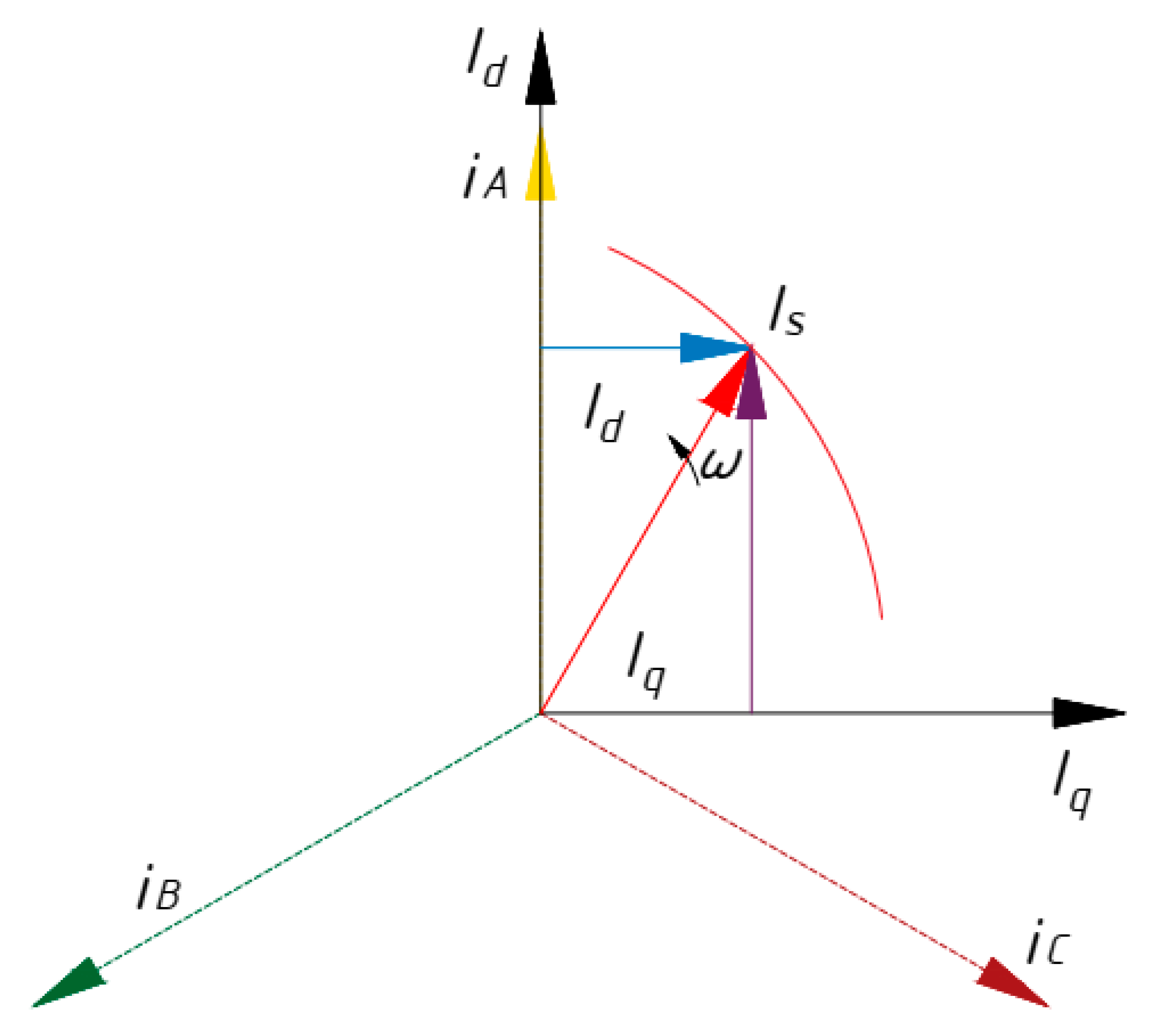
The basic idea of the paper is the Park (Gorev) vector transformations [26], consisting of the transition to a two-phase current system (id, iq) in the rotating coordinate system-dq from the three-phase current system consumed by the induction motor (iA, iB, iC,) [27] by the following mathematical Equations (1) and (2). These equations are valid for the real electric motor [28,29,30].
where
id, iq—currents consumed by an asynchronous motor (AM) in a 2-phase rotating coordinate system-dq;
iA, iB, iC—currents consumed by an asynchronous motor (AM) in a 3-phase rotating coordinate system-ABC.
Assuming that the asynchronous motor is a reference and is a three-phase symmetrical active-inductive load, the following equations are valid (3) and (4)
where
imax—maximum amplitude value of phase current, A;
ω—power angular frequency, rad/s;
t—time, s.
In a coordinate system-dq, the generalized vector of IS current is written as (5) and is valid for (1–4).
These mathematical transformations are shown in a vector diagram, Figure 1.
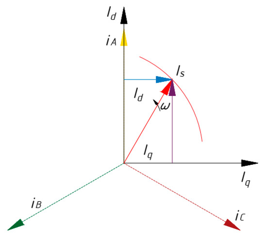
Figure 1.
Vector diagram of Park’s transformation (Gorev).
According to Equation (5), the generalized vector in the complex plane will describe a trajectory—the hodograph. The distortion of the real current vector trajectory with respect to the reference one is observed.
If the asynchronous motor is defective in terms of stator, rotor or mechanical damage, the hodograph of the generalized current vector changes relative to the reference. If one of the stator phases is damaged, the hodograph degenerates into an ellipse. The proportional change in ellipticity and width of the Park’s vector hodograph corresponds to the defect level [21]. Disturbance in the rotor causes the hodograph to degenerate into a complex shape [22]. Damage to the mechanical part of the motor gives rise to circular distortions and variations in the width of the described hodograph [20]. The study of complex trajectories makes it possible to determine the types and intensity of the influence of defects on the rotor speed and torque on the motor shaft in a comprehensive manner.
In this paper, a neural network classifier is used to identify changes in the Park vector, which allows for estimating changes in the state of the Park vector and signals the onset of a defect in a timely manner.
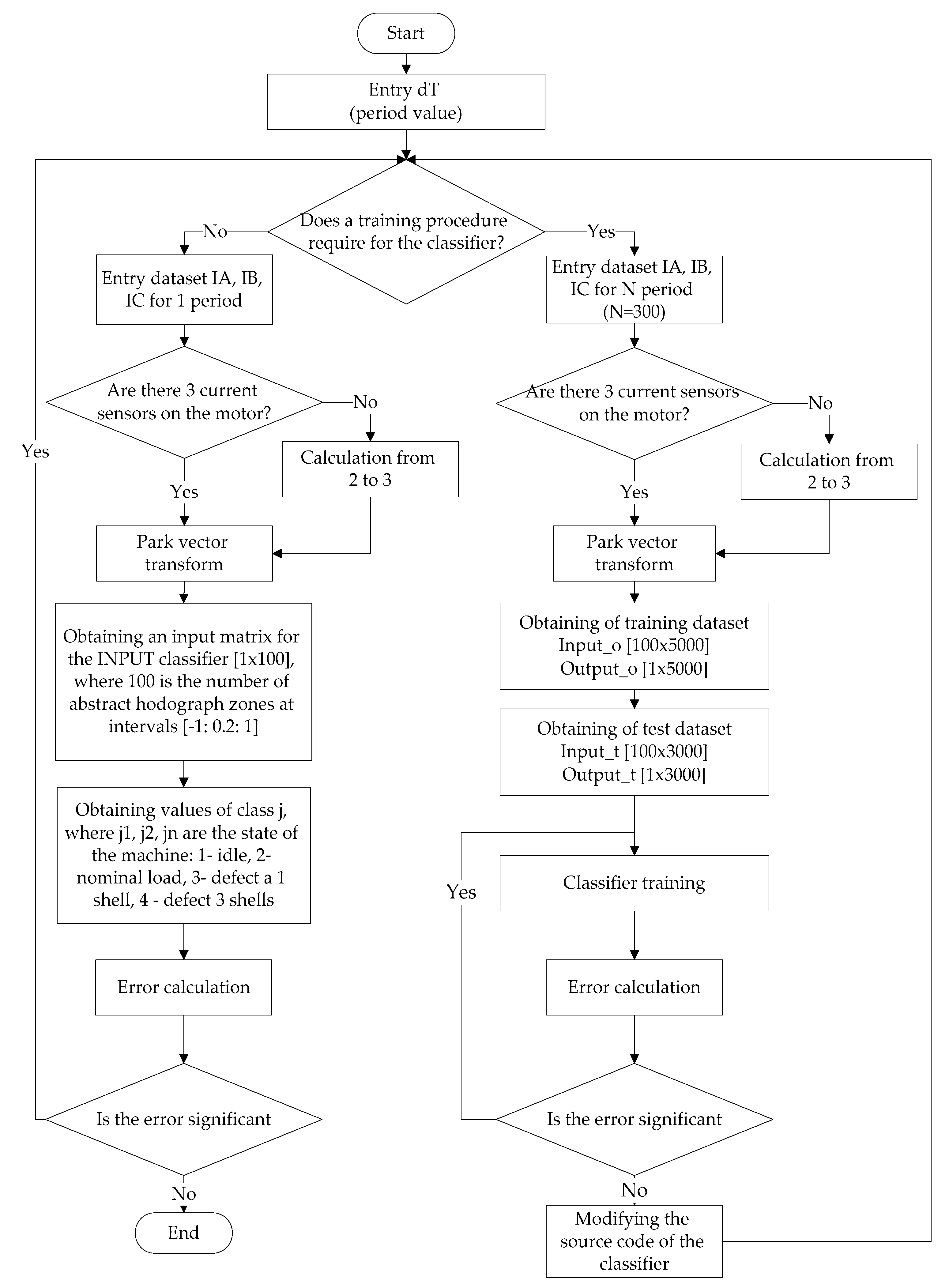
However, in order to use such a classifier, it needs to be adapted to process the data coming in the real-time mode [31,32]. Figure 2 shows the algorithm used in developing the ANN-classifier [33].
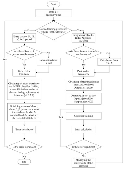
Figure 2.
The algorithm for ANN classifier.
A brief list of actions, according to this algorithm, is as follows: supply values equal to one given time period to the input of the model; obtain values for the Park vector; generate a matrix of values for the input to the classifier; obtain the result. The basic idea, in this case, is the idea of the special formation of the input vector for the ANN-classifier. As such a vector is taken as a vector showing how many times the data vector falls into one or another abstraction region of the Park vectors’ hodograph. In total, the hodograph was divided into 100 abstraction zones from minus 1 to 1 with a step of 0.2 (10 segments on the imaginary and real axis). Thus an array of size (100 × 1) is fed to the input of the ANN-classifier, where the value of each element of the array is the number of points falling into a given abstract zone.
In order to train and test the neural network, the data captured during the experiment were divided into groups. A total of 600,000 values were captured during the experiment. Ten percent was used for training. The rest of the data were used for testing. The important point in training and testing the data was to keep the right sequence. For the network to work correctly, an unbroken vector of data was required for the 1st period of operation. The data were therefore pre-divided into these periods with certain labels.
3. Experiments
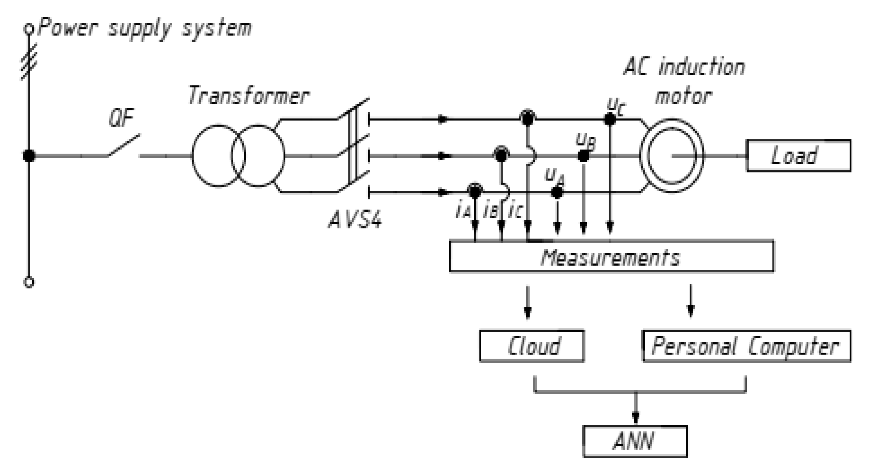
The object of the research is an asynchronous motor with the parameters given in Table 1. It is powered from a 50 Hz mains supply in a continuous duty mode S1 and a constant shaft load. The appearance and wiring diagram of the AM is shown in Figure 3. A similar motor in generator mode gives a constant load.

Table 1.
Nameplate and calculation data for asynchronous motors.

Figure 3.
Asynchronous motor AIR132M4, wiring and measurement diagram.
The impact of bearing failure has the most intense distortion of the magnetic field in the air gap, as shown in Figure 4, as well as in [34]. This type of defect has an increased rate of development, resulting in rapid degradation of the mechanical and associated electrical parts of the motor [35].

Figure 4.
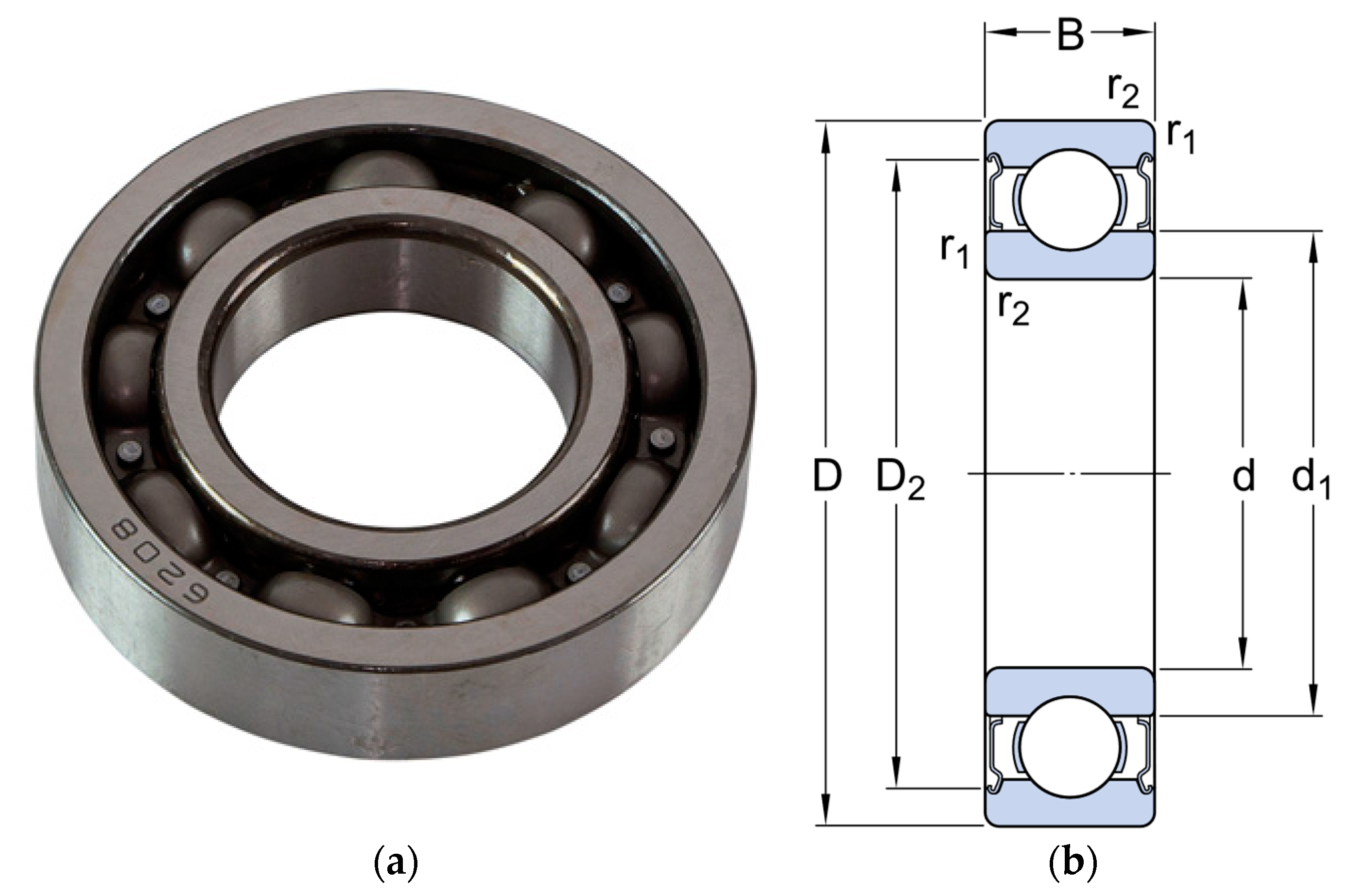
Ball bearings of series—6208: (a)—general view; (b)—sketch of product size.
According to the motor datasheet, the motor AIR132M4 is fitted with deep groove ball bearings series-6208 with the following technical data (Figure 4 and Table 2).
Table 2.
Bearing specifications 6208.
The procedure for the experiment is to artificially degrade the inner rings of the bearing as a number of friction-induced degradation shells in the deep-groove ball bearing. The degradation shells are shown in Figure 5.
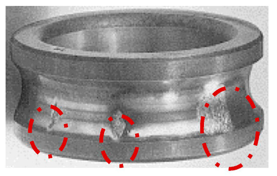
Figure 5.
Degradation shells of a deep-groove ball bearing.
The experiment was carried out on four states of the machine:
- Reference motor operation without load at idle speed
- Motor operation in reference condition at rated load
- Motor operation with one shell in the inner ring of the bearing
- Motor operation with three shells in the inner bearing ring
Tests in cases 3 and 4 were carried out at nominal load.
4. Results & Discussion
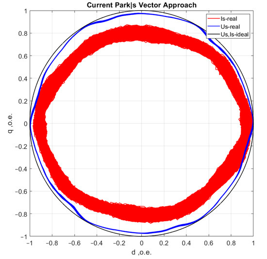
Figure 6.
Reference motor operation without load at idle speed.
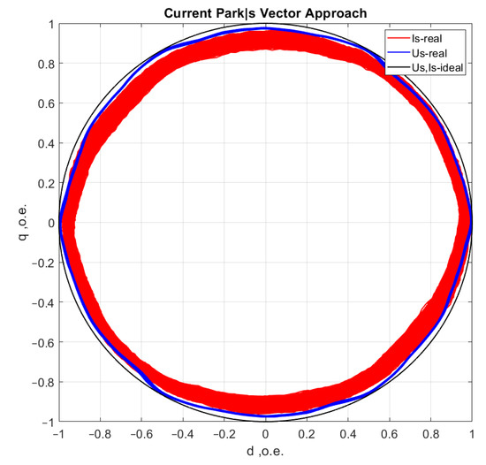
Figure 7.
Motor operation in reference condition at rated load.
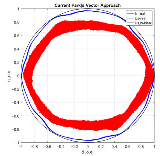
Figure 8.
Motor operation with one shell in the inner ring of the bearing.

Figure 9.
Motor operation with three shells in the inner bearing ring.
A visual assessment of the hodographs in Figure 6, Figure 7, Figure 8 and Figure 9 makes it possible to assert that the Park vector changes its state depending on the cases under consideration. The additional evidence for the expediency of using Park’s vector is shown below.
Study [30] on the spectral analysis of the current consumption of an electric motor highlights the characteristic frequencies by which the presence of a defect can be determined (6). The initial stage of bearing wear is the occurrence of contact parts with rolling elements, namely balls, on the inner or outer ring.
where
frm—rotor speed;
n—number of balls in the bearing;
β—contact angle;
Dpit—diameter of the circumference of the ball centres;
Dball—ball diameter.
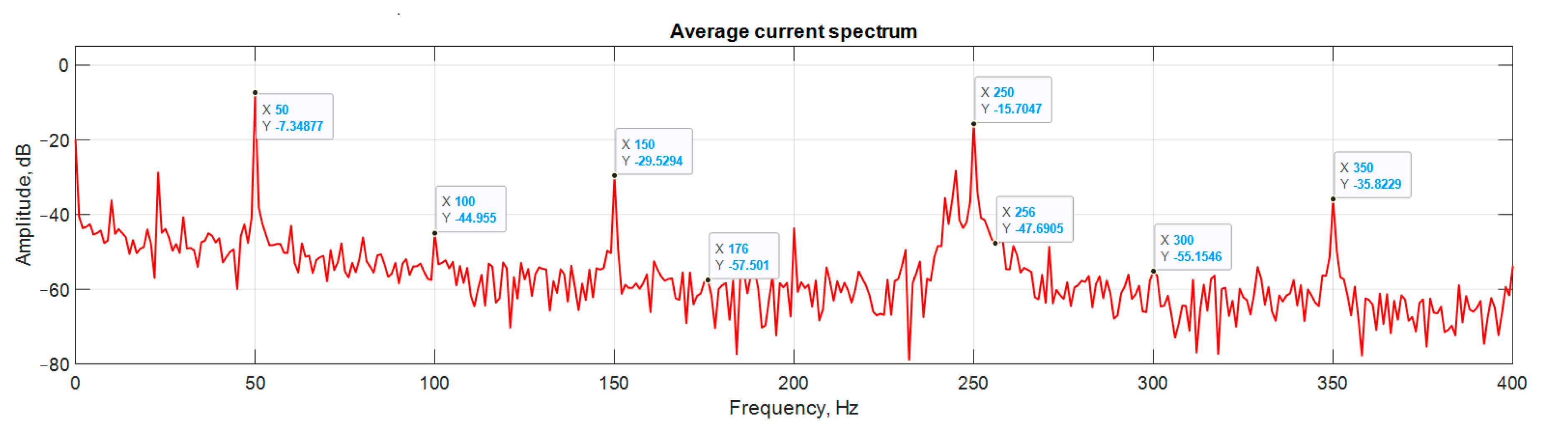
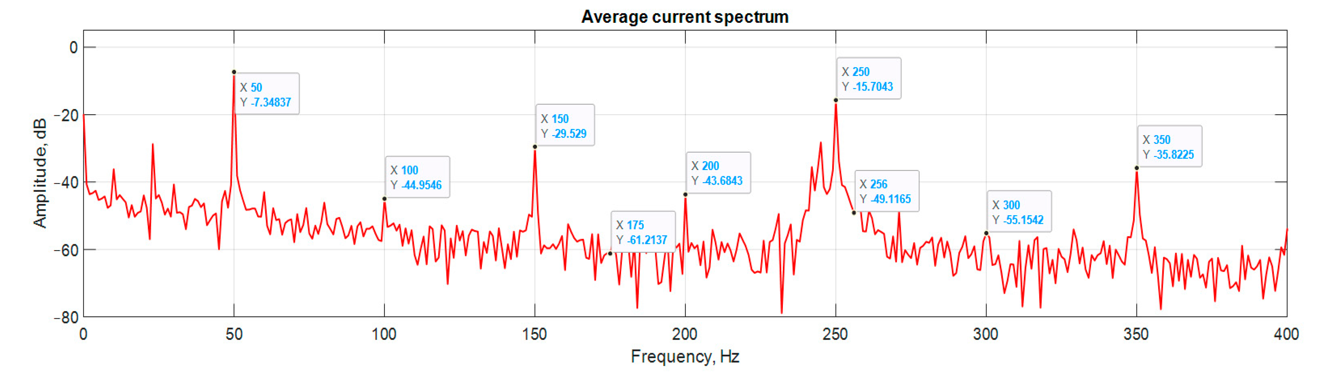
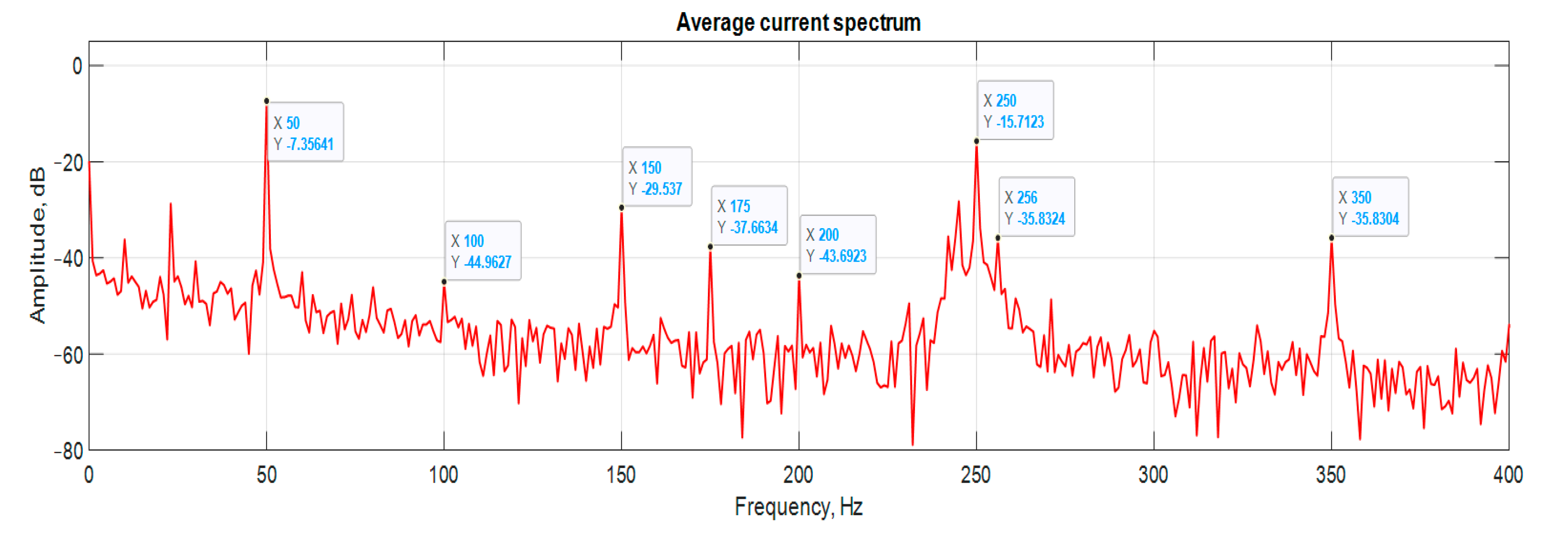
Compared to spectrum analysis (FFT) [36], where part of the information is lost due to the use of low and high-pass filters and is in the noise region (−75–80 dB), it is almost impossible to detect the initial stages of the defect. The occurrence of a defect (in our case a bearing defect) in the hodograph can be detected earlier as a distortion in its trajectory (Figure 10), which the spectrum does not provide. The expected calculated bearing fault frequencies according to (6) and Table 2 at cos β = 1 are frb = 175 Hz, 256 Hz. By analyzing the hodographs and spectra (Figure 10, Figure 11, Figure 12, Figure 13, Figure 14 and Figure 15) changes in the current hodograph (Figure 10) are observed as the defect degree changes. However, it is difficult to isolate the peaks of the frequency components of the spectrum, which is an advantage of the generalized current vector method. However, due to the visual identification of faults in the trajectory distortion hodograph, it is not possible to construct a fault-level estimation system.
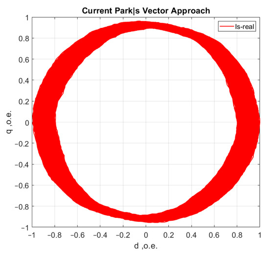
Figure 10.
The hodograph at the start of the defect.
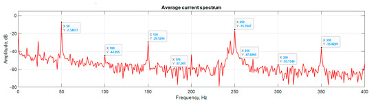
Figure 11.
Spectrum at the start of the defect.
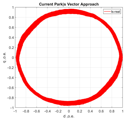
Figure 12.
The hodograph without any defects.

Figure 13.
Spectrum without any defects.
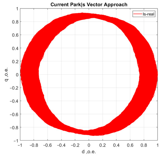
Figure 14.
The hodograph at medium defect.
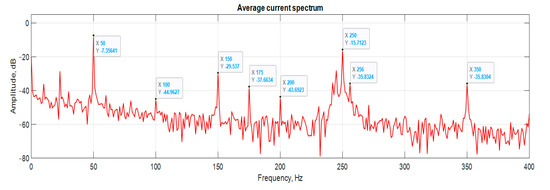
Figure 15.
The spectrum at medium defect.
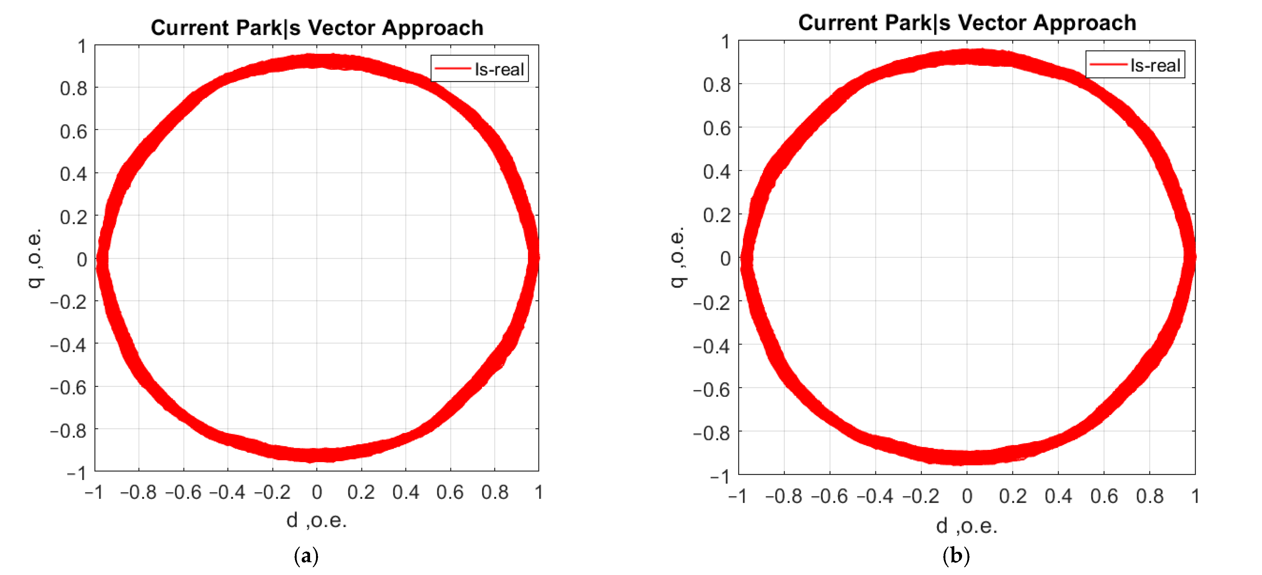
Further analysis of the method has highlighted a number of advantages. The first is that only two current sensors (Hall-effect compensated current sensors) are required to detect faults, as shown in Figure 16. The third phase current is determined indirectly [37,38,39].
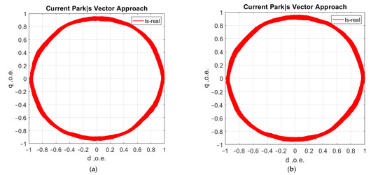
Figure 16.
AM current consumption hodographs: (a) when recording A, B, C phase currents; (b) when recording A and C phase currents.
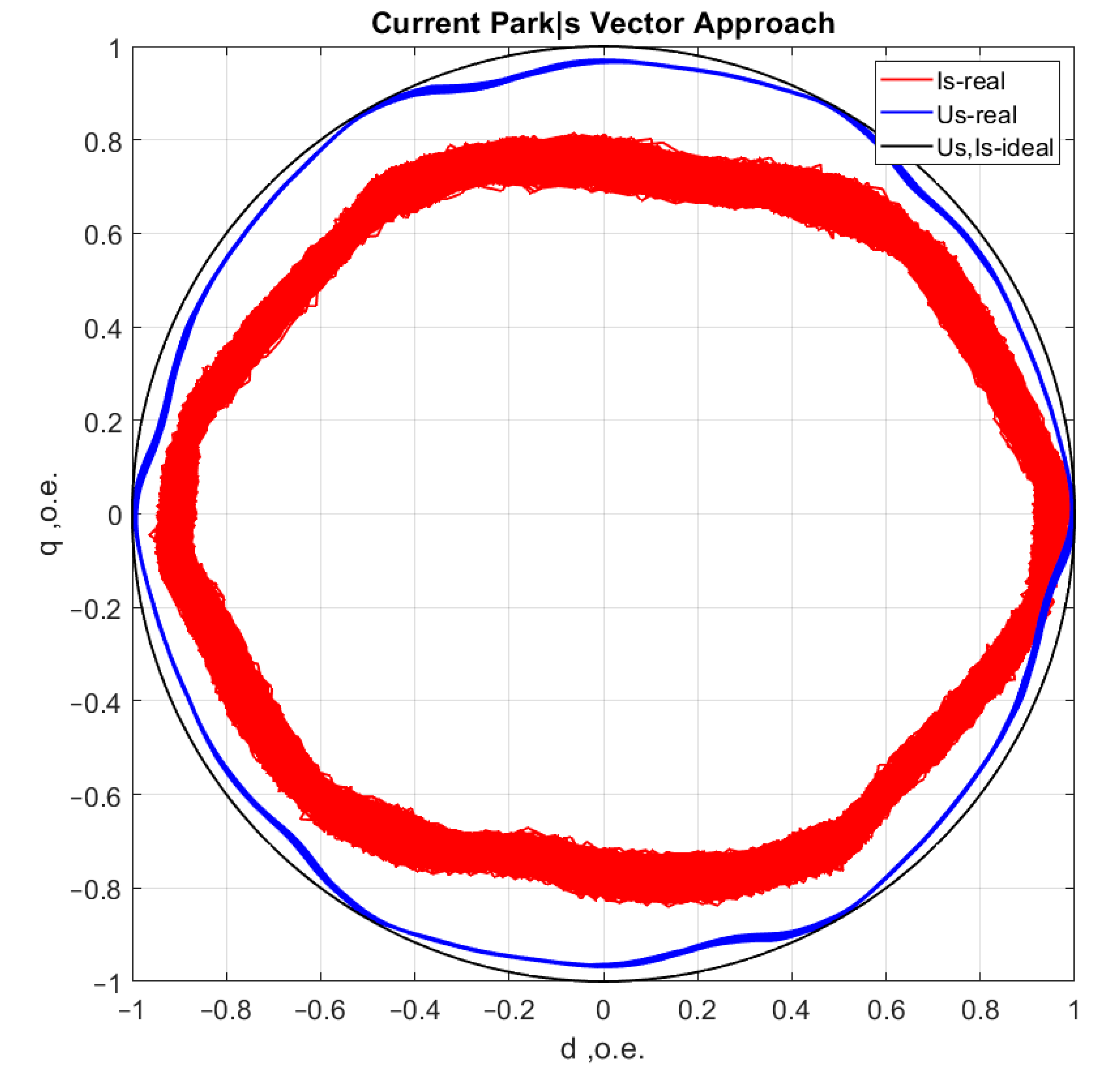
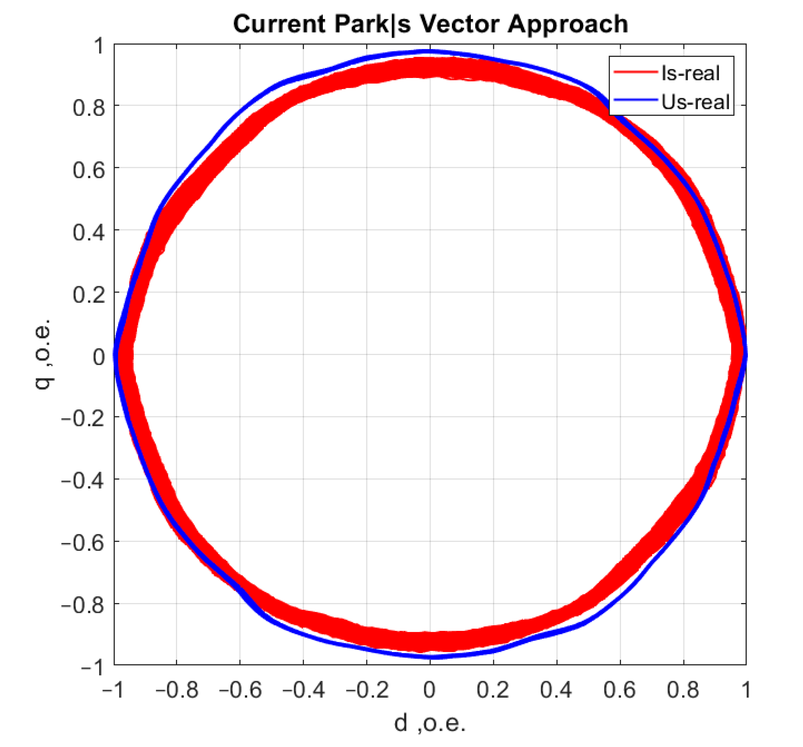
The second is achieved by a synchronous recording of the phase voltage currents (uA, uB, uC), which eliminates the influence of mains distortion. Distortions due to mains quality [40] have to be mutually excluded in the analysis from the asynchronous motor hodograph, (Figure 17).
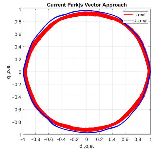
Figure 17.
AM current consumption (red) and supply voltage (blue).
The information value of the hodograph is quite high, but in addition to the trajectories already obtained and their changes to which certain stages and types of both individual and complex defects correspond [41].
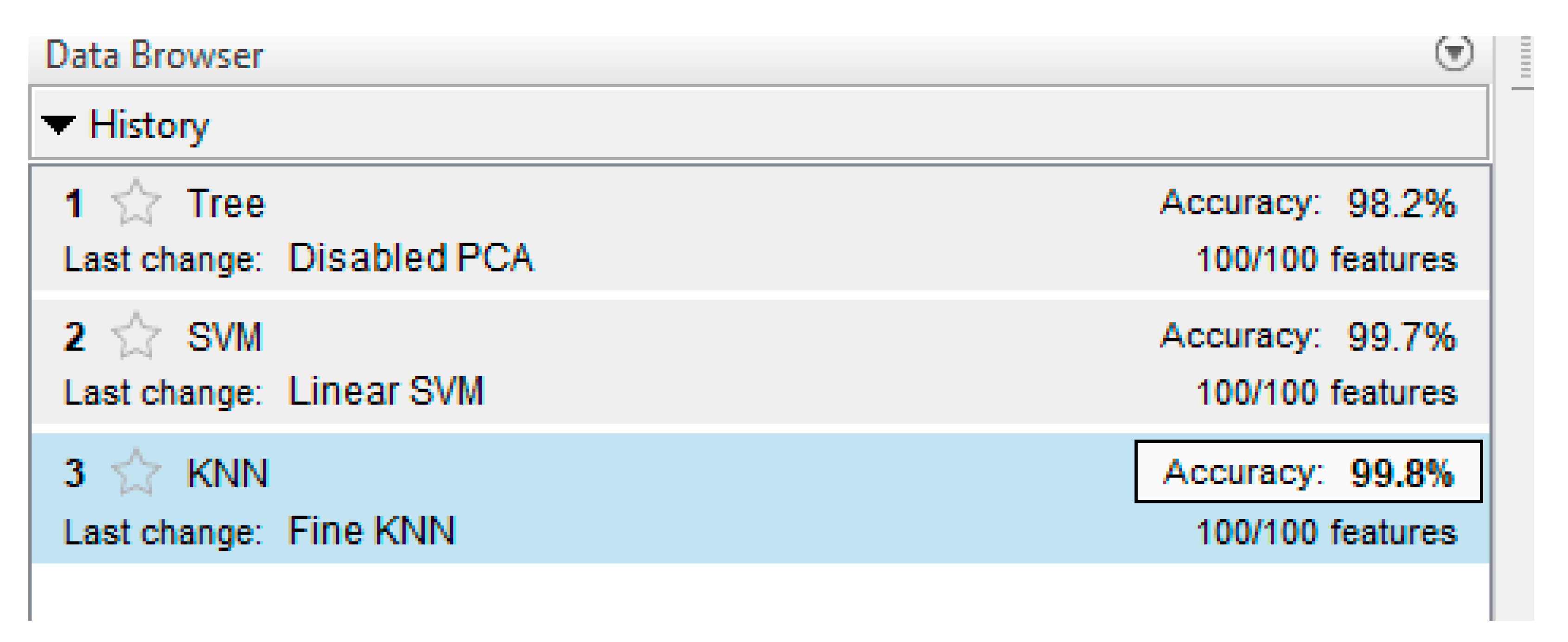
Figure 18 shows the results of training the ANN-classifier. The classifier was trained using three methods: Decision Tree [42], Support Vector Machine [43] and K-nearest neighbors [44].
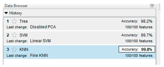
Figure 18.
ANN-classifier learning result.
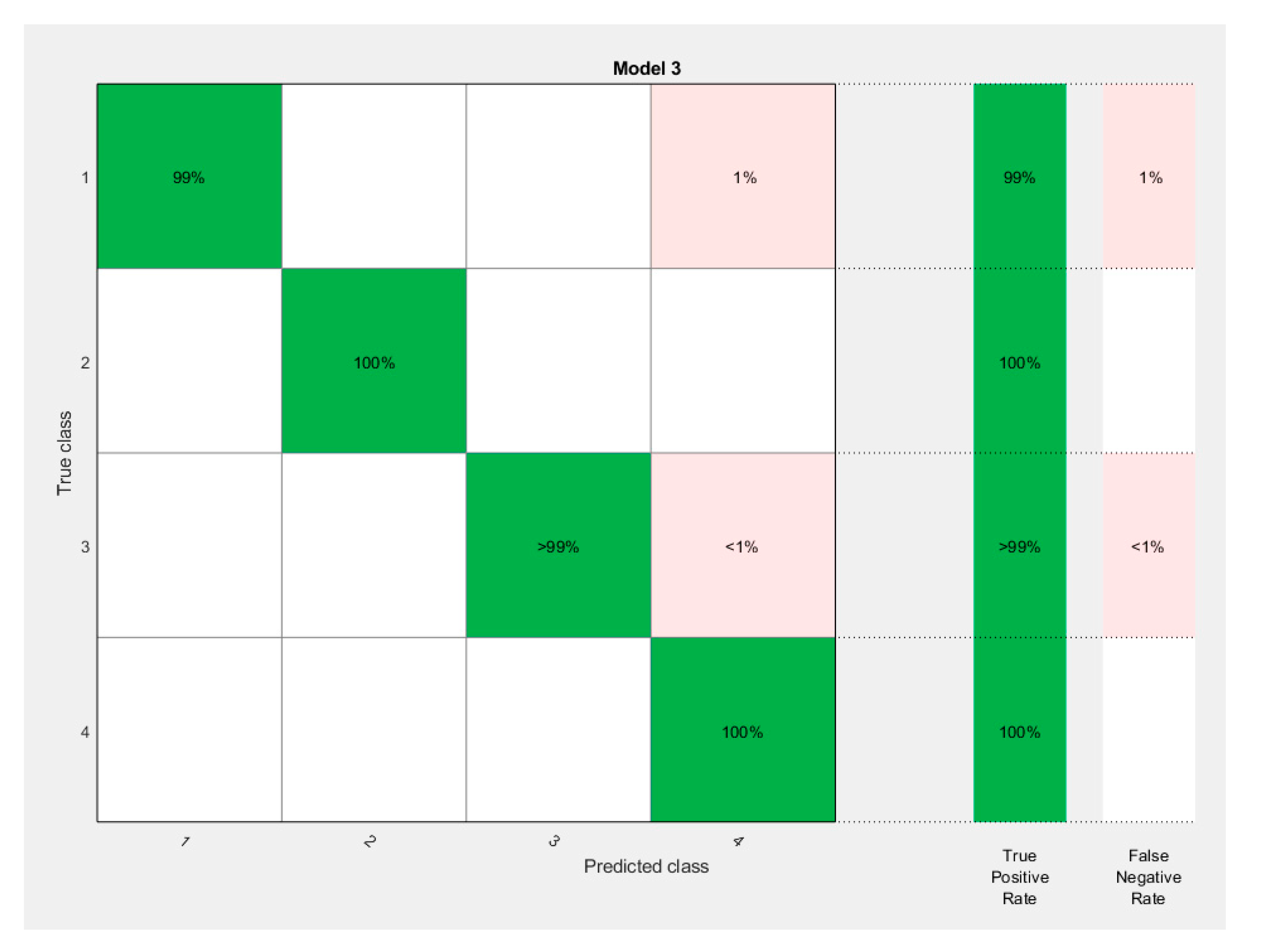
As can be seen in the Figure, the best was K-nearest neighbors, with an accuracy of 99.9%. This is a good result. Figure 19 shows the result as a confusion matrix.

Figure 19.
ANN-classifier learning result. Confusion matrix.
Testing the ANN-classifier algorithm on real data gave significant results as well. The accuracy was 98%. The excessively high accuracy of the results is due to the idealized conditions of the experiment. Under real-life conditions, the machine can be subject to several types of defects [45]. It may operate under disturbing conditions and at different modes. This paper has shown the validity of the proposed methodology, however, for real objects it may not give such high results. However, the authors believe that in order to make it applicable to real objects it is necessary to break the Park hodograph into smaller abstract zones. This would solve the problem of possible overlapping distortions of Park’s vector.
5. Conclusions
In the course of the work, on the whole, it was possible to prove the consistency of the hypothesis. Machine defects can be estimated using a mathematical apparatus that allows the combination of Park’s vector transformation and an ANN-classifier. Using this mathematical apparatus in the real-time mode with a certain periodicity allows us to work out the fully-fledged soft sensor for measuring a certain type of defect. However, the accuracy of the results obtained in the work may be reduced in conditions of real operation of electrical machines. The authors emphasize that the basic idea of the method when these conditions occur will not change. Only the components of this methodology will change, for example, the number of abstract zones in the division of the Park hodograph will increase.
The authors thus offer a method of determining the condition of a bearing in near real-time, or with a minimum decision time. The authors have shown that it is possible to tell just by one spin of the Park hodograph, i.e., by one period (0.02 s) that a bearing has developed a defect. This can be carried out by applying a special ANN-classifier, which in turn determines which of the predefined abstract zones the current Park vector values fall into. The division into such zones or quadrants is the basic tool for improving the accuracy of the soft sensor. The closer the bearing conditions are to ideal, the larger the abstract zones that are allocated. However, it must be remembered that the allocation of such zones is initially laid down and their extension is not possible during operation, i.e., on the go. Therefore, experiments under real-field conditions should be carried out beforehand to determine the necessary width of the considered abstract zones for the Park hodograph.
Author Contributions
Conceptualization, N.K. (Nikolay Korolev) and N.K. (Natalia Koteleva); methodology, N.K. (Nikolay Korolev) and N.K. (Natalia Koteleva); software, G.B.; experiments, N.K. (Natalia Koteleva); writing—original draft preparation, N.K. (Nikolay Korolev) and N.K. (Natalia Koteleva); writing—review and editing, Y.Z.; visualization, N.K. (Nikolay Korolev) and N.K. (Natalia Koteleva); supervision, Y.Z.; project administration, Y.Z. All authors have read and agreed to the published version of the manuscript.
Funding
The study was carried out at the expense of a subsidy for the fulfillment of the state task in the field of scientific activity for 2021 No. FSRW-2020-0014.
Institutional Review Board Statement
Not applicable.
Informed Consent Statement
Not applicable.
Acknowledgments
The study was carried out at the expense of a subsidy for the fulfillment of the state task in the field of scientific activity for 2021 No. FSRW-2020-0014.
Conflicts of Interest
The authors declare no conflict of interest.
References
- Vasilyeva, N.V.; Boikov, A.V.; Erokhina, O.O.; Trifonov, A.Y. Automated digitization of radial charts. J. Min. Inst. 2021, 247, 82–87. [Google Scholar] [CrossRef]
- Safina, E.; Khokhlov, S. Paradox of alternative energy consumption: Lean or profligacy? Int. J. Qual. Res. 2017, 11, 903–916. [Google Scholar] [CrossRef]
- Litvinenko, V. Digital Economy as a Factor in the Technological Development of the Mineral Sector. Nat. Resour. Res. 2020, 29, 1521–1541. [Google Scholar] [CrossRef]
- Abramovich, B.N.; Veprikov, A.A.; Sychev, Y.A.; Lyakh, D.A. Use of active power transducers in industrial DC power systems supplying electrolysis cells. Tsvetnye Met 2020, 2, 95–100. [Google Scholar] [CrossRef]
- Sychev, Y.; Zimin, R. Improving the quality of electricity in the power supply systems of the mineral resource complex with hybrid filter-compensating devices. J. Min. Inst. 2021, 247, 132–140. [Google Scholar] [CrossRef]
- Filatova, I.; Nikolaichuk, L.; Zakaev, D.; Ilin, I. Public-Private Partnership as a Tool of Sustainable Development in the Oil-Refining Sector: Russian Case. Sustainability 2021, 13, 5153. [Google Scholar] [CrossRef]
- Belsky, A.A.; Dobush, V.; Haikal, S.F. Operation of a Single-phase Autonomous Inverter as a Part of a Low-power Wind Complex. J. Min. Inst. 2019, 239, 564–569. [Google Scholar] [CrossRef]
- Kulkarni, A.; Terpenny, J.; Prabhu, V. Sensor Selection Framework for Designing Fault Diagnostics System. Sensors 2021, 21, 6470. [Google Scholar] [CrossRef]
- Kalista, K.; Liska, J.; Jakl, J. A Vibration Sensor-Based Method for Generating the Precise Rotor Orbit Shape with General Notch Filter Method for New Rotor Seal Design Testing and Diagnostics. Sensors 2021, 21, 5249. [Google Scholar] [CrossRef]
- Hsu, J. Monitoring of defects in induction motors through air-gap torque observation. IEEE Trans. Ind. Appl. 1995, 31, 1016–1021. [Google Scholar] [CrossRef]
- Bessous, N.; Zouzou, S.E.; Bentrah, W.; Sbaa, S.; Sahraoui, M. Diagnosis of bearing defects in induction motors using discrete wavelet transform. Int. J. Syst. Assur. Eng. Manag. 2018, 9, 335–343. [Google Scholar] [CrossRef]
- Gundewar, S.K.; Kane, P.V. Condition Monitoring and Fault Diagnosis of Induction Motor in Electric Vehicle. In Lecture Notes in Mechanical Engineering; Springer: Singapore, 2021; Volume 531–537. [Google Scholar] [CrossRef]
- Ewert, P.; Kowalski, C.T.; Orlowska-Kowalska, T. Low-Cost Monitoring and Diagnosis System for Rolling Bearing Faults of the Induction Motor Based on Neural Network Approach. Electronics 2020, 9, 1334. [Google Scholar] [CrossRef]
- Lo, N.G.; Soualhi, A.; Frini, M.; Razik, H. Gear and bearings fault detection using motor current signature analysis. In Proceedings of the 2018 13th IEEE Conference on Industrial Electronics and Applications (ICIEA), Wuhan, China, 31 May–2 June 2018; Volume 137520, pp. 900–905. [Google Scholar] [CrossRef]
- Sunder, M.; Abishek, R.; Sabarivelan, S.; Maiti, M.; Bingi, K. Bearing Fault Detection in Induction Motors Using Line Currents. ECTI Trans. Electr. Eng. Electron. Commun. 2021, 19, 209–219. [Google Scholar] [CrossRef]
- El Bouchikhi, E.H.; Choqueuse, V.; Amirat, Y.; Benbouzid, M.E.H.; Turri, S. An Efficient Hilbert–Huang Transform-Based Bearing Faults Detection in Induction Machines. IEEE Trans. Energy Convers. 2017, 32, 401–413. [Google Scholar] [CrossRef]
- Kompella, K.D.; Rao, M.V.G.; Rao, R.S. Bearing fault detection in a 3 phase induction motor using stator current frequency spectral subtraction with various wavelet decomposition techniques. Ain Shams Eng. J. 2018, 9, 2427–2439. [Google Scholar] [CrossRef]
- Fournier, E.; Picot, A.; Regnier, J.; Yamdeu, M.T.; Andrejak, J.-M.; Maussion, P. Current-Based Detection of Mechanical Unbalance in an Induction Machine Using Spectral Kurtosis with Reference. IEEE Trans. Ind. Electron. 2014, 62, 1879–1887. [Google Scholar] [CrossRef] [Green Version]
- Gyftakis, K.N.; Cardoso, A.J.M.; Antonino-Daviu, J.A. Introducing the Filtered Park’s and Filtered Extended Park’s Vector Approach to detect broken rotor bars in induction motors independently from the rotor slots number. Mech. Syst. Signal Process. 2017, 93, 30–50. [Google Scholar] [CrossRef]
- Cruz, A.J.M.C.S.M.A. Rotor Cage Fault Diagnosis in Three-Phase Induction Motors by Extended Park’s Vector Approach. Electr. Mach. Power Syst. 2000, 28, 289–299. [Google Scholar] [CrossRef]
- Silva, J.; Cardoso, A. Bearing failures diagnosis in three-phase induction motors by extended Park’s vector approach. In Proceedings of the 31st Annual Conference of IEEE Industrial Electronics Society, Raleigh, NC, USA, 6–10 November 2005; pp. 2591–2596. [Google Scholar] [CrossRef]
- Caseiro, J.A.A.; Mendes, A.; Cardoso, A.J.M. Fault diagnosis on a pwm rectifier ac drive system with fault tolerance using the average current Park’s Vector approach. In Proceedings of the 2009 IEEE International Electric Machines and Drives Conference, Miami, FL, USA, 3–6 May 2009; Volume 5075281, pp. 695–701. [Google Scholar] [CrossRef]
- Curreri, F.; Patanè, L.; Xibilia, M.G. Soft Sensor Transferability: A Survey. Appl. Sci. 2021, 11, 7710. [Google Scholar] [CrossRef]
- Dybkowski, M.; Klimkowski, K. Artificial Neural Network Application for Current Sensors Fault Detection in the Vector Controlled Induction Motor Drive. Sensors 2019, 19, 571. [Google Scholar] [CrossRef] [PubMed] [Green Version]
- Zhou, X.; Mao, S.; Li, M. A Novel Anti-Noise Fault Diagnosis Approach for Rolling Bearings Based on Convolutional Neural Network Fusing Frequency Domain Feature Matching Algorithm. Sensors 2021, 21, 5532. [Google Scholar] [CrossRef]
- Mendes, A.; Cardoso, A.M. Voltage source inverter fault diagnosis in variable speed AC drives, by the average current Park’s vector approach. In Proceedings of the IEEE International Electric Machines and Drives Conference, Seattle, WA, USA, 9–12 May 1999; Volume 6314016, pp. 704–706. [Google Scholar] [CrossRef]
- Muñoz-Aguilar, R.-S.; Rodriguez, P.; Dòria-Cerezo, A.; Candela, I.; Luna, A. A sensor-less sliding mode control scheme for a stand-alone wound rotor synchronous generator under unbalanced load conditions. Int. J. Electr. Power Energy Syst. 2014, 60, 275–282. [Google Scholar] [CrossRef]
- Cornell, E.P.; Lipo, T.A. Modeling and Design of Controlled Current Induction Motor Drive Systems. IEEE Trans. Ind. Appl. 1977, 4, 321–330. [Google Scholar] [CrossRef]
- Thomson, W.; Fenger, M. Current signature analysis to detect induction motor faults. IEEE Ind. Appl. Mag. 2001, 7, 26–34. [Google Scholar] [CrossRef]
- Thomson, W.T.; Fenger, M.; Lloyd, B. Development of a tool to detect faults in induction motors via current signature analysis. In Proceedings of the 2003 IEEE-IAS/PCA Cement Industry Conference, Dallas, TX, USA, 20 June 2003. [Google Scholar] [CrossRef]
- Khan, M.J.; Mathew, L. Artificial neural network-based maximum power point tracking controller for real-time hybrid renewable energy system. Soft Comput. 2021, 25, 6557–6575. [Google Scholar] [CrossRef]
- Muruganandam, M.; Madheswaran, M. Stability analysis and implementation of chopper fed DC series motor with hybrid PID-ANN controller. Int. J. Control Autom. Syst. 2013, 11, 966–975. [Google Scholar] [CrossRef]
- Sancho-Asensio, A.; Orriols-Puig, A.; Golobardes, E. Robust on-line neural learning classifier system for data stream classification tasks. Soft Comput. 2014, 18, 1441–1461. [Google Scholar] [CrossRef]
- He, F.; Xie, G.; Luo, J. Electrical bearing failures in electric vehicles. Friction 2020, 8, 4–28. [Google Scholar] [CrossRef] [Green Version]
- Pandarakone, S.E.; Mizuno, Y.; Nakamura, H. A Comparative Study between Machine Learning Algorithm and Artificial Intelligence Neural Network in Detecting Minor Bearing Fault of Induction Motors. Energies 2019, 12, 2105. [Google Scholar] [CrossRef] [Green Version]
- Ameid, T.; Menacer, A.; Talhaoui, H.; Harzelli, I. Rotor resistance estimation using Extended Kalman filter and spectral analysis for rotor bar fault diagnosis of sensorless vector control induction motor. Measurement 2017, 111, 243–259. [Google Scholar] [CrossRef]
- Vasilyev, B.Y.; Shpenst, V.A.; Kalashnikov, O.V.; Ulyanov, G.N. Providing energy decoupling of electric drive and electric grids for industrial electrical installations. J. Min. Inst. 2018, 229, 41–49. [Google Scholar] [CrossRef]
- Shklyarskiy, Y.; Skamyin, A.; Vladimirov, I.; Gazizov, F. Distortion Load Identification Based on the Application of Compensating Devices. Energies 2020, 13, 1430. [Google Scholar] [CrossRef] [Green Version]
- Lavrenko, S.; Shishlyannikov, D. Performance Evaluation of Heading-and-Winning Machines in the Conditions of Potash Mines. Appl. Sci. 2021, 11, 3444. [Google Scholar] [CrossRef]
- Bichurin, M.; Petrov, R.; Leontiev, V.; Semenov, G.; Sokolov, O. Magnetoelectric Current Sensors. Sensors 2017, 17, 1271. [Google Scholar] [CrossRef] [Green Version]
- Diab, A.A.Z.; Ebraheem, T.; Aljendy, R.; Sultan, H.M.; Ali, Z.M. Optimal Design and Control of MMC STATCOM for Improving Power Quality Indicators. Appl. Sci. 2020, 10, 2490. [Google Scholar] [CrossRef] [Green Version]
- Decision Tree. In Encyclopedia of Database Systems; Springer: Singapore, 2009; p. 765.
- Evgeniou, T.; Pontil, M. Support Vector Machines: Theory and Applications. In Machine Learning and Its Applications. ACAI 1999. Lecture Notes in Computer Science; Paliouras, G., Karkaletsis, V., Spyropoulos, C.D., Eds.; Springer: Berlin/Heidelberg, Germany, 2001; Volume 2049, pp. 249–257. [Google Scholar] [CrossRef] [Green Version]
- Cunningham, P.; Delany, S.J. k-Nearest Neighbour Classifiers—A Tutorial. ACM Comput. Surv. 2021, 54, 1–25. [Google Scholar] [CrossRef]
- Turysheva, A.; Voytyuk, I.; Guerra, D. Estimation of Electricity Generation by an Electro-Technical Complex with Photoelectric Panels Using Statistical Methods. Symmetry 2021, 13, 1278. [Google Scholar] [CrossRef]


Publisher’s Note: MDPI stays neutral with regard to jurisdictional claims in published maps and institutional affiliations. |
© 2021 by the authors. Licensee MDPI, Basel, Switzerland. This article is an open access article distributed under the terms and conditions of the Creative Commons Attribution (CC BY) license (https://creativecommons.org/licenses/by/4.0/).