Article

Efficient Non-Uniform Pilot Design for TDCS

1
China Academy of Launch Vehicle Technology, Beijing 100076, China
2
Beijing Institute of Astronautical Systems Engineering, Beijing 100076, China
*
Author to whom correspondence should be addressed.
Sensors 2021, 21(20), 6880; https://doi.org/10.3390/s21206880
Submission received: 23 September 2021 / Revised: 10 October 2021 / Accepted: 15 October 2021 / Published: 17 October 2021

Abstract

:
The Internet of Things (IoT) leads the era of interconnection, where numerous sensors and devices are being introduced and interconnected. To support such an amount of data traffic, wireless communication technologies have to overcome available spectrum shortage and complex fading channels. The transform domain communication system (TDCS) is a cognitive anti-interference communication system with a low probability of detection and dynamic spectrum sensing and accessing. However, the non-continuous and asymmetric spectrum brings new challenges to the traditional TDCS block-type pilot, which uses a series of discrete symbols in the time domain as pilots. Low efficiency and poor adaptability in fast-varying channels are the main drawbacks for the block-type pilot in TDCS. In this study, a frequency domain non-uniform pilot design method was proposed with intersecting, skewing, and edging of three typical non-uniform pilots. Some numerical examples are also presented with multipath model COST207RAx4 to verify the proposed methods in the bit error ratio and the mean square error. Compared with traditional block-type pilot, the proposed method can adapt to the fast-varying channels, as well as the non-continuous and asymmetric spectrum conditions with much higher efficiency.

1. Introduction

The Internet of Things (IoT) is a global network of interconnected objects, where numerous sensors and devices are interconnected as parts of the internet to expand their efficiency [1]. Wired and wireless networks are ubiquitous in IoT, which largely increases the demand on the spectrum overhead [2,3]. Cognitive radio (CR) is an emerging trend for supporting multiuser and hybrid communications [4,5]. With the combination of IoT and CR concepts, the network is applicable for real-time cognitive radio applications as well as various dynamic environments [6,7,8,9]. Transform domain communication system (TDCS) is a cognitive anti-interference communication system, which is regarded as a promising candidate of CR for the IoT massive multiple access scenarios [10,11]. Unlike orthogonal frequency division multiplexing (OFDM) and multi-carrier code division multiple access (CDMA), TDCS is designed to avoid occupied frequency bins by signal processing facilities at both the transmitter and receiver instead of mitigating the interference only at the receiver [12,13,14]. Therefore, sensing the spectrum at both sides and shaping the transmitting waveform are the key features of TDCS.
In practical applications, TDCS has to adapt to the multipath time-varying channels. Without accurate channel state information (CSI), TDCS either cannot work or may suffer serious performance losses. Besides, the non-continuous and asymmetric spectrum of the transmitter and the receiver make the channel estimation and equalization more difficult. Pilots are a common solution for obtaining the CSI [15]. For TDCS, only block-type pilots are reported in the literature, which periodically inserts certain symbols in the time domain of the transmitting signal. Since pilots appear in all unoccupied frequency bins of the inserted symbols, the block-type pilots are insensitive to the frequency selective fading. In other words, they are only valid for the slow-varying channels, where the CSI is constant during one block [16,17]. Besides, the pilot symbols could not carry data, which reduces the system efficiency. Comb-type pilots are widely used in OFDM [18]. They uniformly distribute in the frequency domain of every symbol, which leads to a better flexibility for the fast-varying channels. Since the CSI is obtained after frequency domain interpolation, comb type pilots are sensitive to the frequency selective fading [19]. However, in TDCS, uniform pilots are not suitable for the non-continuous spectrum conditions [20]. Besides, some convex optimization methods based on non-continuous OFDM are seriously affected by the asymmetric spectrum between the transmitter and the receiver [21]. In this article, a series of efficient non-uniform pilots are proposed in the frequency domain in the forms of intersecting, skewing, and edging types. Compared with the existing pilot types, the proposed methods are more adaptive to the fast-varying channels, as well as the non-continuous and asymmetric spectrum conditions with much higher efficiency.
In Section 2, TDCS and the classification of the typical transmitters and receivers are reviewed as the foundation of the subsequent studies. In Section 3, efficient non-uniform pilots are designed for TDCS, whose performance is also analyzed with comparisons. In Section 4, some numerical examples are presented to verify the proposed methods. The article is then concluded in Section 5.

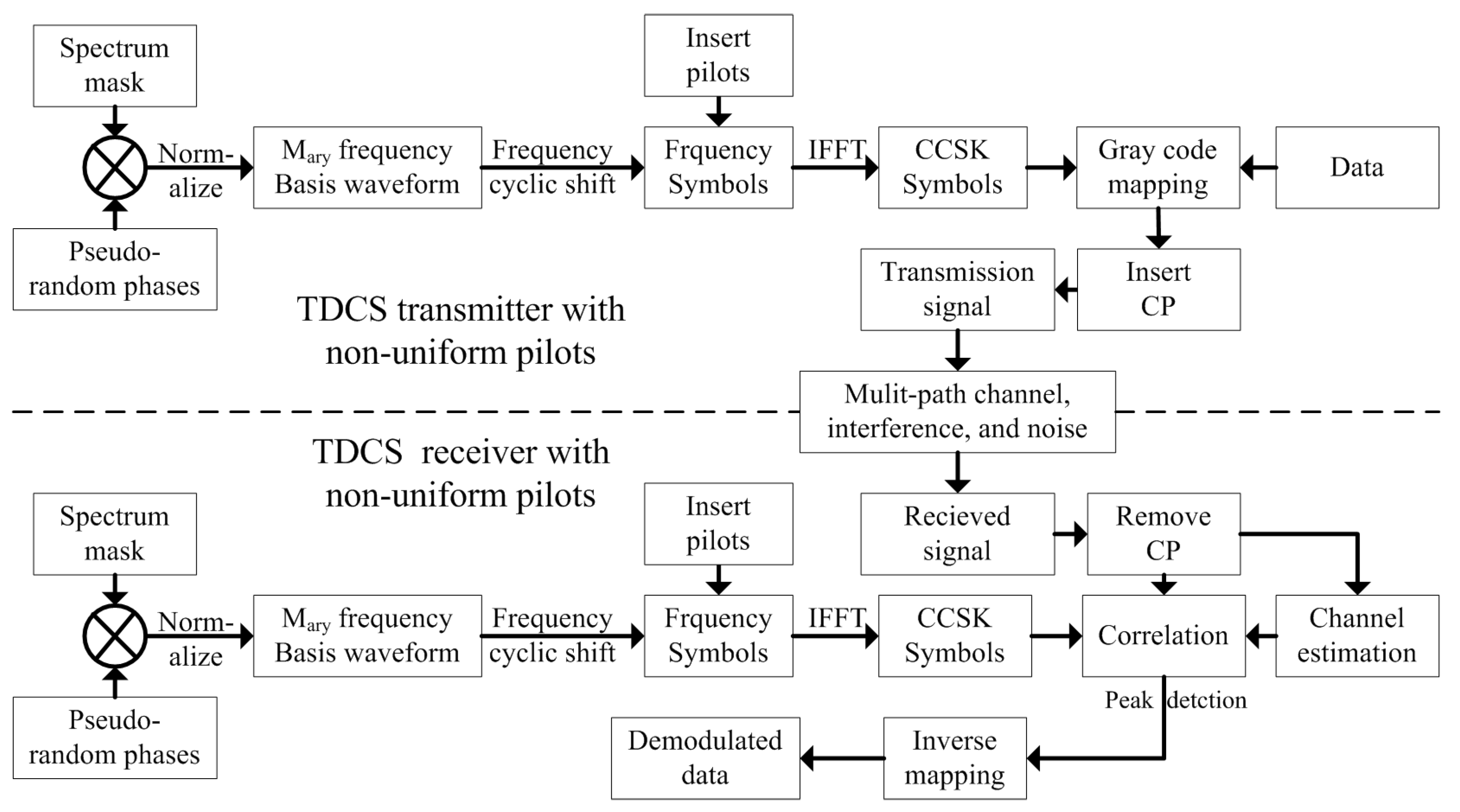
2. TDCS and the Classification of the Transceivers
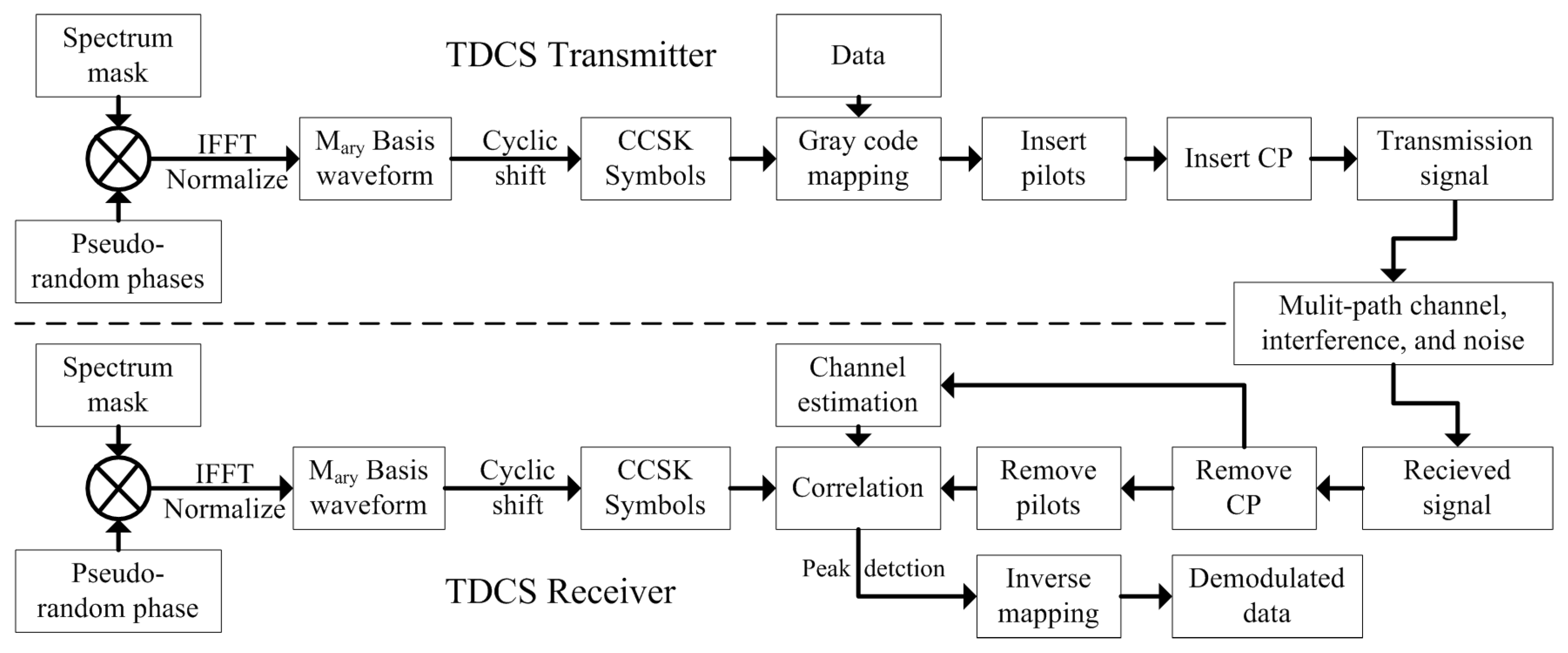
2.1. TDCS Model

The TDCS model is depicted in Figure 1. The transmitter and the receiver independently sense the whole bandwidth to create the spectrum mask A ( k ) , with the value 1 or 0 if the k th frequency bin is unoccupied or interfered. Pseudo-random phases θ k are created by a pseudo-random sequence generator and applied element by the element to the spectrum mask. The resulting vector is then passed through an inverse fast Fourier transform (IFFT) and scaled to the desired power. Then, the basis waveform is cyclic-shifted to modulate data in Gray code. The i th modulated symbol in the frequency and the time domain can be expressed in complex baseband notation as (1) and (2), respectively.
S T D C S , i ( k ) = N N 1 A ( k ) e j θ k e j 2 π m i k / M
s T D C S , i ( n ) = 1 N N 1 k = 0 N 1 A ( k ) e j θ k e j 2 π m i k / M e j 2 π k n / N
In the equations above, N and N 1 are the numbers of the total and the unoccupied frequency bins, respectively. m i [ 1 , M ] is the i th data with M -ary CCSK (cyclic code shift keying) modulation [22].
In the transmitter of TDCS, pilot symbols are then periodically inserted to the modulated symbols in the time domain. After inserting the cycle prefix (CP) to every symbol [23], the transmitting signal is completely generated.
The transmitting signal goes through the multi-path channels with interferences and additive white Gaussian noise (AWGN). In the receiver, the CP is removed from the received signal, the pilots are extracted to estimate the CSI. The rest are the data symbols, which are used for correlation and peak detection with the estimated CSI. Finally, the demodulated data can be obtained by the corresponding inverse mapping.

2.2. The Classification of TDCS Transmitters and Receivers

Considering the influence from predetermined conditions of the frequency domain pilot interval and the practical spectrum mask generation, we can classify TDCS transmitters into two categories:
  • Tx 1;
The two factors above act independently. The pilots are uniformly inserted in the frequency domain of every symbol, which are designed the same as the contiguous spectrum. The practical spectrum mask restricts the interfered frequency bins for transmission [24].
2.
Tx 2;
The practical spectrum mask can influence the frequency domain pilot interval. Exhaustion or convex optimization methods insert pilots non-uniformly in the unoccupied frequency bins.
According to whether the receiver knows the real-time pilots of the transmitter, the receivers can be classified as:
  • Rx 1;
The receiver knows the transmitter practical spectrum mask or the positions of the pilots. Some spectrum exchange mechanisms were implemented to obtain the accurate pilots for channel estimation and interpolation. If the pilot design method is known, pilots on the symmetric frequency bins of both Tx 1 and Tx 2 type can be obtained.
2.
Rx 2;
The receiver does not know the transmitter practical spectrum mask. This means there is no spectrum exchange between the transmitter and the receiver. If the spectrum is symmetric, the receiver can obtain the accurate pilot positions. For asymmetric spectrum conditions, partial pilots on the asymmetric frequency bins of Tx 1 type would be influenced. However, almost all pilots of Tx 2 type are influenced since different spectrum masks lead to entirely different pilot positions, and orders are confused [25].
Actually, the transmitter and the receiver of TDCS usually work in the non-continuous and asymmetric spectrum conditions. The spectrum exchange mechanism would occupy too much control signaling spending [26]. Therefore, to ensure Rx-2-type receivers work properly, the transmitter should be modified based on the Tx 1 type.

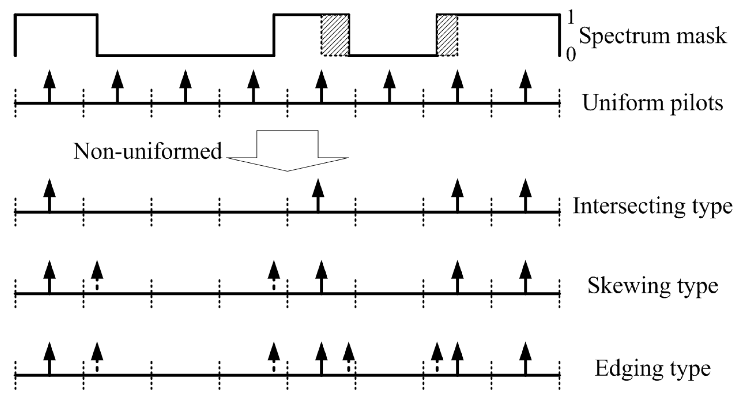
3. Efficient Non-Uniform Pilot Design for TDCS

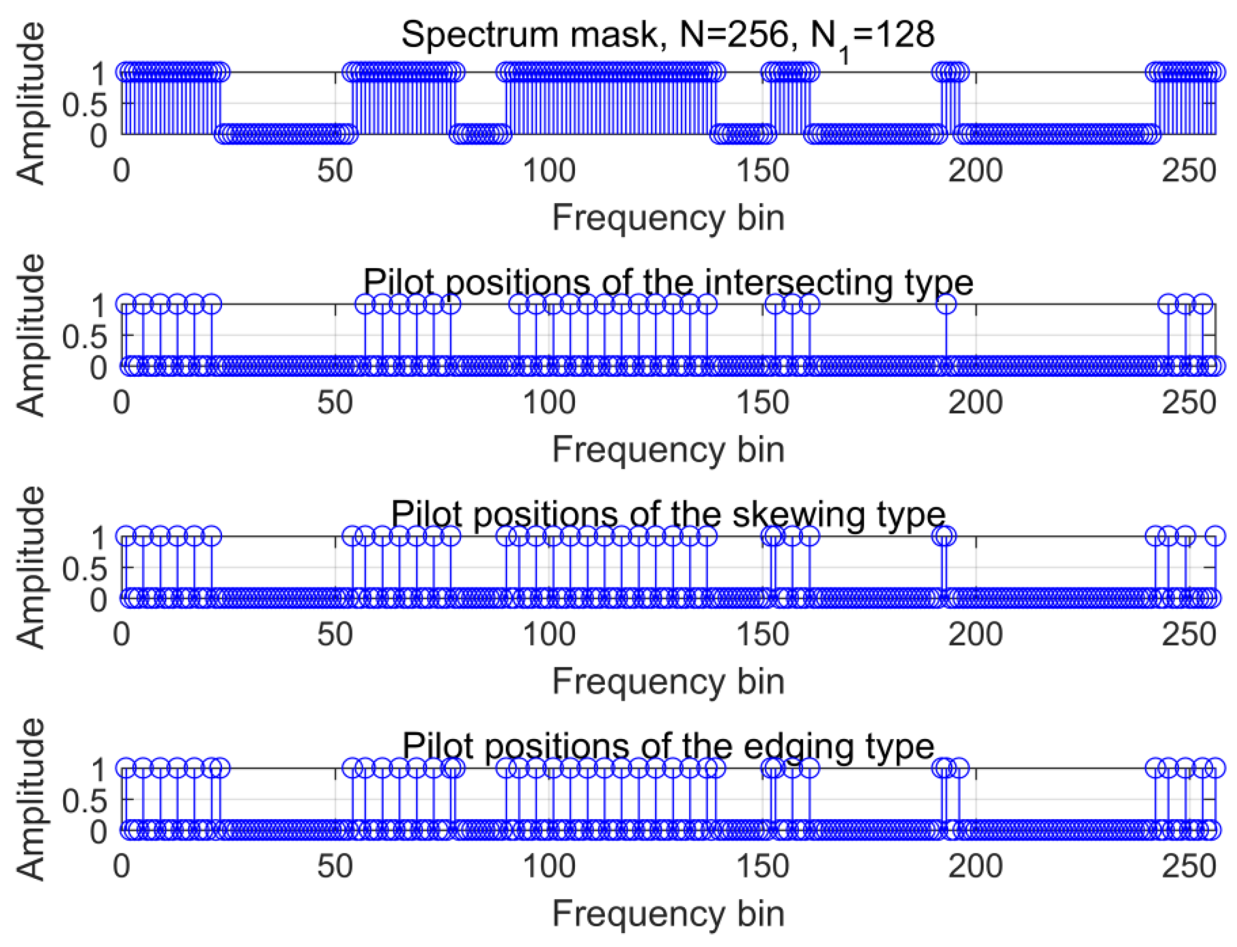
3.1. Non-Uniform Pilot Design

For uniform pilots, according to the Nyquist sampling theorem [27], to restore frequency domain signal without distortion, the corresponding time domain extension period should be less than the maximum delay spread.
N f 1 τ max Δ f
In (3), N f is the minimum pilot interval in the frequency domain, Δ f is the interval between adjacent frequency bins, and τ max is the maximum multipath delay. As shown in Figure 2, the spectrum of the whole bandwidth is divided into N s segments (separated with the dotted lines), and the uniform pilots lie in the center of every segment.
To fit the non-continuous and asymmetric spectrum conditions, we designed non-uniform pilots gradually. The simplest method is to directly use the intersecting between the uniform pilots and the practical spectrum mask. The positions of intersecting type P int ( k ) can be designed as the uniform type pilot.
P int ( k ) = P u n i f o r m ( k ) A ( k )
P u n i f o r m ( k ) is the uniform pilot mask with a value 1 or 0 if the k th position is pilot or not. In the positions of P int ( k ) = 1 , the values of the pilots S int ( k ) can be designed as the absolute values of the frequency domain basis waveform.
S int ( k ) = { | S T D C S , i ( k ) | ,   p i l o t   p o s i t i o n s S T D C S , i ( k ) , e l s e
The intersecting type is restricted by the practical spectrum mask. However, some segments are usually partly unoccupied with the uniform pilot positions interfered. This means the segments carry information, but no corresponding pilots are inserted to the segments. Therefore, the CSI of those segments could not be estimated, and their carried information may not be correctly demodulated. To solve the problem above, we designed skewing-type non-uniform pilots by appropriately skewing the pilots in the segments.
The skewing type was designed based on the intersecting type, if the uniform pilot position is unoccupied or the whole segment is interfered, which was set the same as the intersecting type. If the segment is partly unoccupied with the uniform pilot position interfered, the pilot position should skew using the following rule.
O = [ 1 , + 1 , 2 , + 2 N / N s 1 2 , + N / N s 1 2 ]
In (6), O is the value of the skewing and and + mean skewing in descending and ascending order within the segment, respectively. The values of the pilots are the same as the intersecting type in (5). As shown in Figure 2, the extra dotted arrowed pilots in the skewing type ensure the partly interfered segments can be estimated. Therefore, the most applicative spectrum conditions for the skewing type are dispersive and dense to ensure every segment has a valid pilot.
We assumed that the availability of each frequency bin within the total bandwidth N follows a binomial distribution B ( N , p ) , where p is the probability of the availability. If only one pilot is inserted in each segment, the probability of the none frequency bin is available within a continuous s frequency bins, which could be deduced.
P ( s , p ) = ( 1 p ) s
According to (7), for the typical case with p = 0.5 and s = 8 , the probability could be easily calculated as P ( 8 , 0.5 ) = 0.0039 , which would hardly happen. In other words, a valid pilot would be correctly inserted into every segment to achieve the channel estimation in the vast majority of cases. However, in actual fact, compared with multi-tone interference occupying on different frequency bins, narrowband or wideband interference are more common [28]. Therefore, to obtain a compete channel response, the restored frequency domain pilots must be interpolated, with frequently used constant interpolation, Gaussian interpolation, or cubic spline interpolation [29].
If the spectrum conditions are aggregate and sparse, the edges of the segments could not be correctly interpolated and estimated. In Figure 2, the shaded parts of the spectrum mask could not be interpolated for the non-valid pilot between them. We designed the edging type pilot based on the skewing type. Extra pilots were inserted in the edges of every interference (continuous zeros in the spectrum mask) with the vales as (5). In Figure 2, the dotted arrowed pilots in the edging type are the extra pilots.

3.2. System Design with Non-Uniform Interpolation, Estimation, and Equalization

TDCS with frequency domain non-uniform pilots in Figure 3 is quite different with a time domain pilot system in Figure 1. To avoid the extra process in the time domain, we directly generated M -ary frequency symbols in the frequency domain by multiplying spectrum mask, pseudo-random phases, and CCSK phases 2 π mk / M .
S m ( k ) = N N 1 A ( k ) e j θ k e j 2 π m k / M
In (8), m [ 1 , M ] is the sequence of M -ary CCSK. Then, the pilots were inserted in different types mentioned above with the absolute values of S m ( k ) in the pilot positions to generate CCSK symbols S m , p i l o t ( k ) .
S m , p i l o t ( k ) = { | S m ( k ) | , p i l o t   p o s i t i o n s S m ( k ) , e l s e
The i th signal with data m i can be expressed.
s i ( n ) = 1 N N 1 k = 0 N 1 S m i , p i l o t ( k ) e j 2 π k n / N
To eliminate the inter-symbol interference (ISI), the length of CP follows the rule as (11) [30].
L C P τ max t s = τ max f s
In (11), τ max is the maximum multi-path delay and f s and t s are the sampling frequency and sampling period, respectively.
In the receiver, the removed CP signal r i ( n ) was used for demodulation. According to the non-uniform pilot positions, we extracted pilots P i ( k ) from R i ( k ) , which is the FFT of r i ( n ) .
R i ( k ) = 1 N k = 0 N 1 r i ( n ) e j 2 π k n / N
We used the least squares (LS) method [31] to estimate the channel response in the frequency domain.
H ^ i ( k ) = P i ( k ) P i , l o c a l ( k )
In (13), H ^ i ( k ) was only valid in the pilot positions, while others were set as zero. P i , l o c a l ( k ) is the local accurate pilot. H ^ i ( k ) was non-uniform, and interpolation was necessary to fill the whole channel response according to the existing pilots. Uniform linear interpolation is first-order and fits the small pilot interval conditions. Uniform Gaussian and cubic spline interpolations are high-order, which leads to the variance of noise being doubled.
In this study, we regarded uniform linear interpolations between every adjacent non-uniform pilots as non-uniform linear interpolation to obtain the whole channel response H ^ i , intp ( k ) .
H ^ i , intp ( x ) = ( 1 q x p q 1 ) H ^ i ( q ) + ( 1 x p p q 1 ) H ^ i ( p )
In (14), p and q were the adjacent pilots. x ( p , q ) are the interpolated positions. Minimum mean square error (MMSE) equalization [32] was used to eliminate the multi-path influence. The signal after equalization r i , M M S E ( n ) could be deduced.
r i , M M S E ( n ) = 1 N N 1 k = 0 N 1 R i ( k ) F i ( k ) e j 2 π k n / N
F i ( k ) = C ( H ^ i , intp ( k ) ) H ^ i , intp ( k ) C ( H ^ i , intp ( k ) ) + σ n 2 I 1 × N
In the two equations above, σ n 2 is the variance of the AWGN, I 1 × N is the all-ones matrix with one row and N columns. C ( x ) means the conjugate of a complex matrix x .
To keep the signal-to-noise ratio (SNR) in the same level, we demodulated with pilots by using s m ( n ) (the time domain CCSK symbols with pilots) in the receiver to correlate with r i , M M S E ( n ) . The peak detection and inverse mapping were the same as traditional TDCS in Figure 1.

3.3. Performance Analysis

For the time-domain block-type pilots, the pilots themselves occupied the symbols that are used for carrying information. Similar to (3), the sampling rate 1 / N t T should be not less than twice the signal bandwidth. The intervals between symbols can be expressed as (17). The efficiency N t can be defined as (18), which declines with the number of pilots.
N t 1 2 f d T
In (17), f d is the Doppler frequency, and T is the symbol duration. N t is the time domain interval according to the Nyquist sampling theorem.
η t = N t N t + 1
In TDCS, the CCSK constellation size M should meet the dimensionality theorem to ensure orthogonality [33].
M N 1
For frequency domain pilots, the pilots themselves occupy only some frequency bins rather than whole symbols. However, the pilots still occupy the power of those frequency bins, which are used for carrying information. The efficiency η f can be defined as Equation (20). Especially, based on (19), if it satisfies M + N p N 1 , the efficiency of the TDCS with frequency domain non-uniform pilots can be constant η f = 1 .
η f = { N 1 N p N 1 ,           M + N p > N 1    1 ,                   M + N p N 1
In (20), N p is the number of the non-uniform pilots. M frequency bins ensure the CCSK orthogonality, while other N p frequency bins were used as pilots. The N p pilots just occupied the surplus dimensions.
The pilots were contained in every symbol, which made frequency domain non-uniform pilots fit to the fast-varying channels. The mean square error (MSE) can be expressed as (21).
M S E ( H ^ i , intp ) = E { ( H ^ i , intp ( k ) H i ( k ) ) A ( k ) 2 }
In (21), H i is the true channel response with pilots in all unoccupied frequency bins. E { } is the mean of all unoccupied frequency bins.
Compared with convex optimization methods [34,35], the proposed methods ensure that the symmetric part of the frequency bins could be correctly estimated and equalized. The asymmetric part cannot be accumulated to the matching peak of the correlated demodulation in the receiver. Therefore, the SNR loss only appeared in the asymmetric parts.

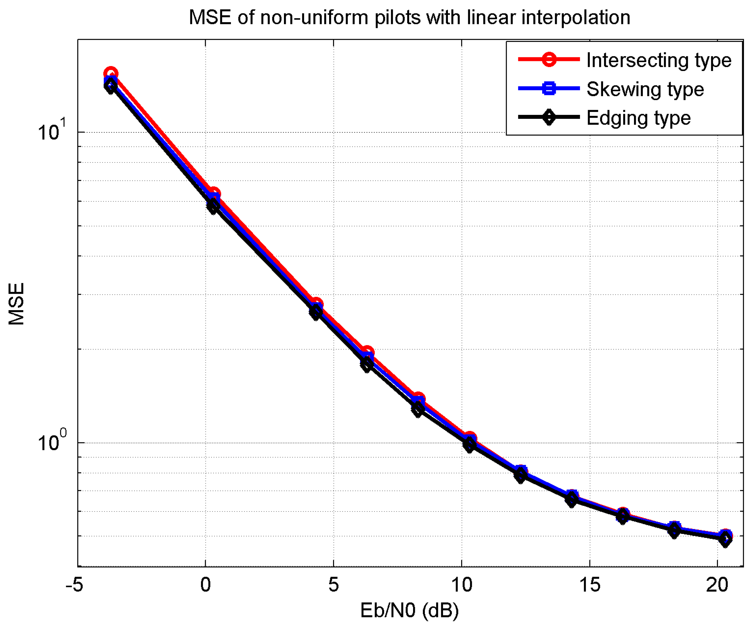
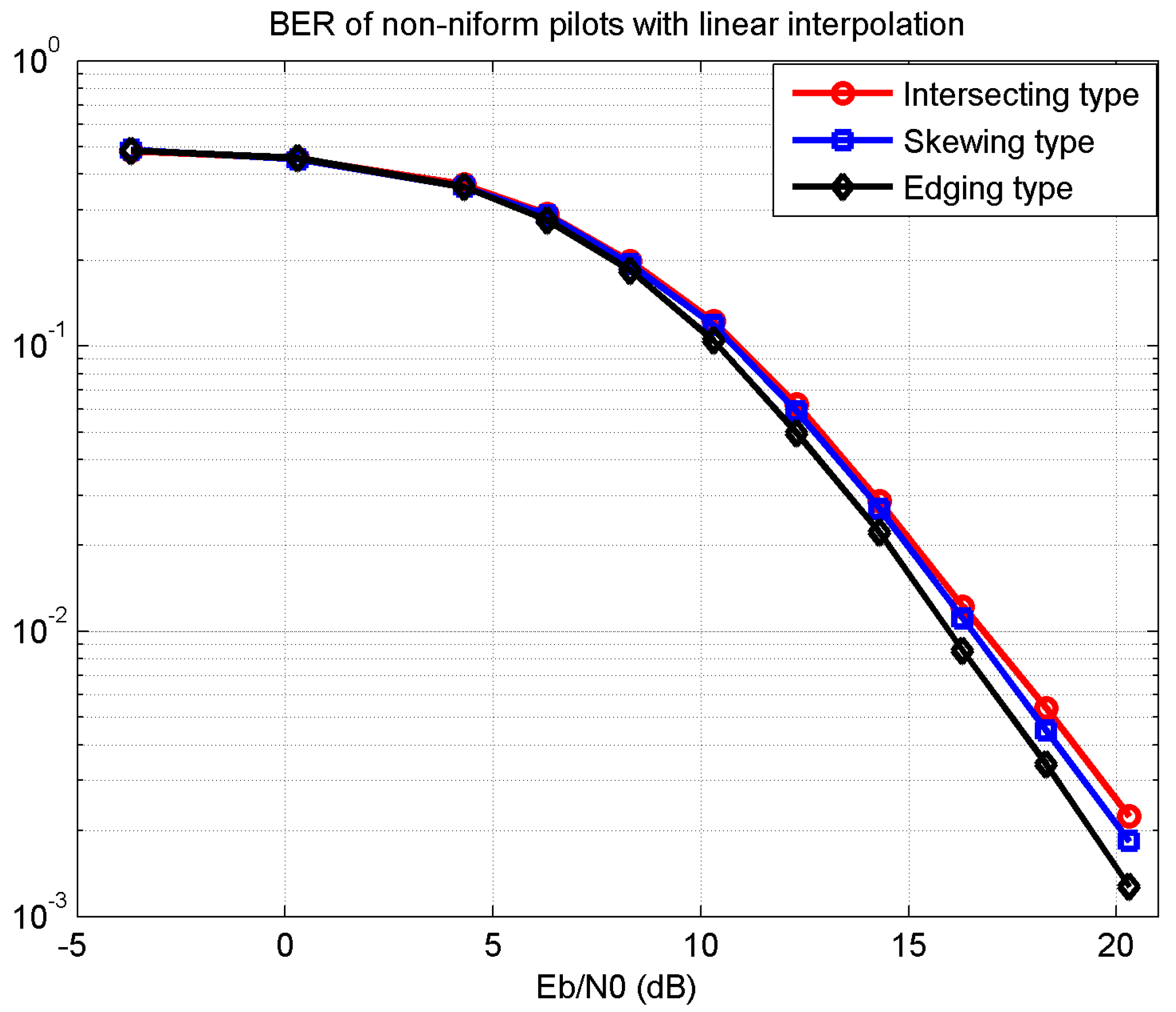
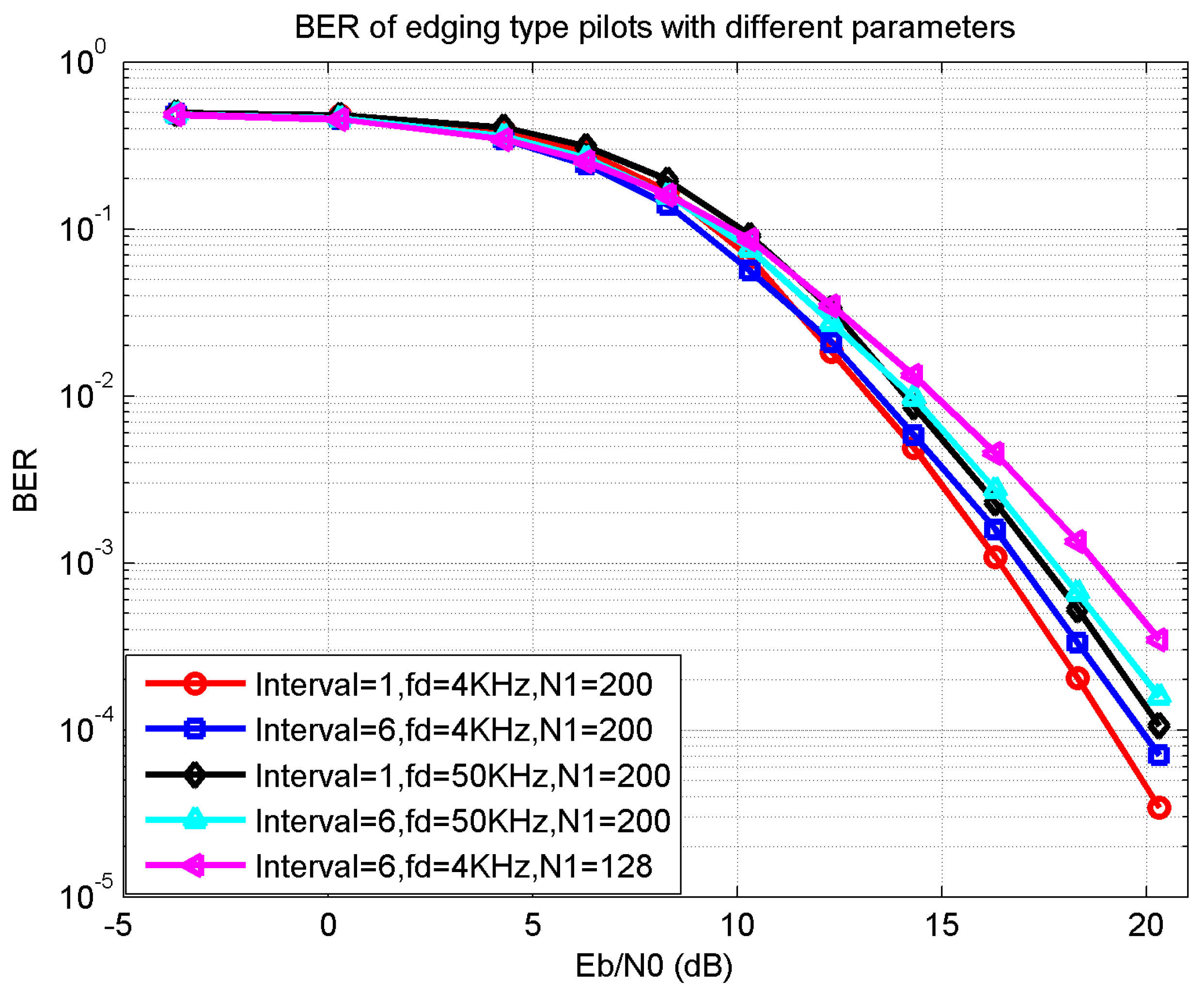
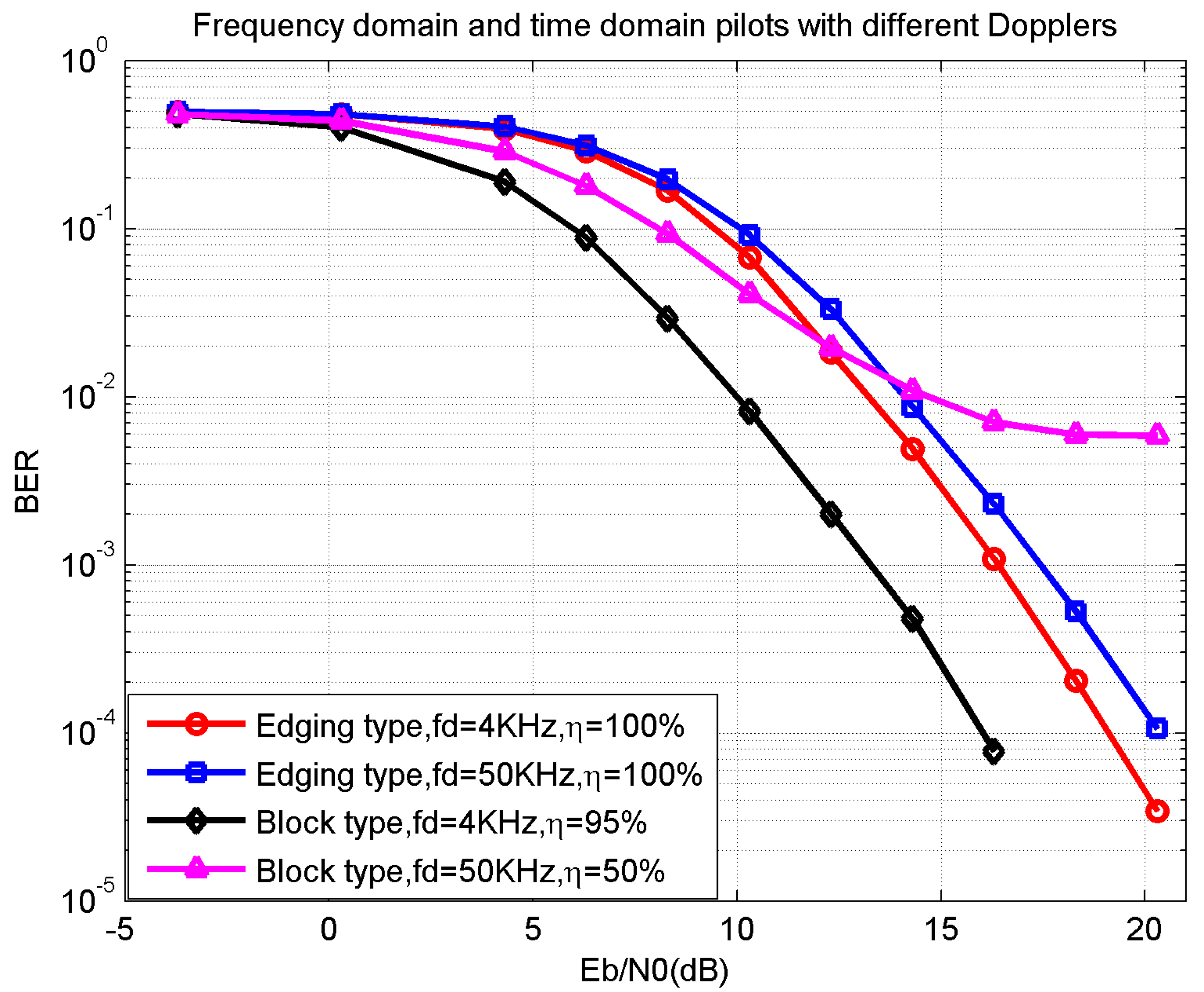
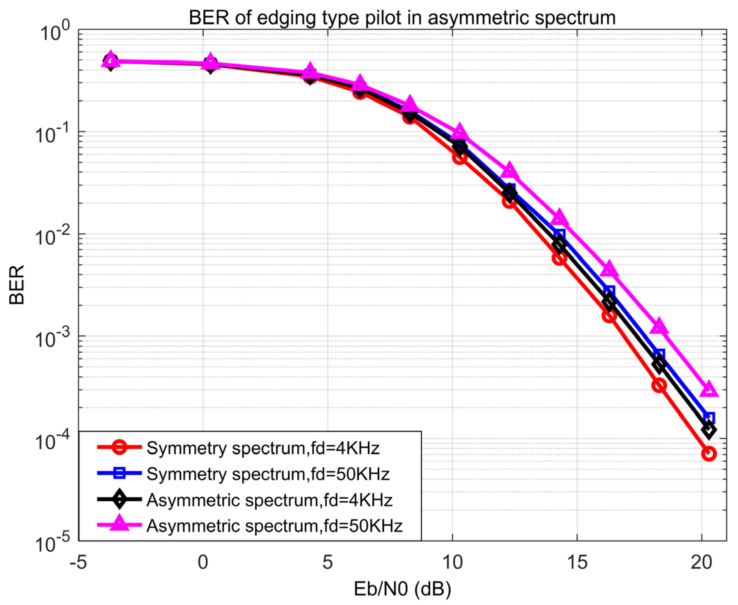
4. Numerical Simulations

In this section, some numerical examples are simulated to verify the proposed methods. The parameters were set as bandwidth B = 60   MHz , number of frequency bins N = 256 , and multipath model COST207RAx4 [36,37]. The bandwidth of every frequency bin was 234   KHz , while other signals and interferences in the L band could be regarded as large frequency blocks. Therefore, the spectrum mask was composed of interfered and unoccupied frequency blocks.
According to (5) and (6), the non-uniform pilot positions of the intersecting, the skewing, and the edging types are located as Figure 4 with N 1 = 128 and uniform pilot initial interval two frequency bins. Corresponding to the spectrum mask in the first row, the pilots’ positions are listed with in the bandwidth. To exactly restore the TDCS signal parts in the unoccupied frequency blocks as shown in the spectrum mask, the numbers of the skewing- and edging-type pilots were slightly greater than the intersecting type with an extra five and seven pilots, respectively.
Figure 5 shows the MSE of the three proposed pilot types with linear interpolation. The MSE decreases with SNR E b / N 0 ,which implies that AWGN enlarges the difference between the estimated and the actual channel response. The number of the practical inserted pilots was slightly different, as in Figure 4, which led to that channel’s estimation performance of the edging-type pilot being slightly better than the others.
Figure 6 shows the BER performance of the three proposed pilot types with linear interpolation. The channel estimation of the edging type pilot was more accurate than the others; therefore, it needed a much lower SNR E b / N 0 of 1 dB gap at BER 10 3 . The differences in Figure 5 and Figure 6 also reflect the effect of certain key pilots for the channel estimation and equalization performance.
In Figure 7, the BER performance of the edging type pilots was simulated with different parameters. The initial interval between two adjacent pilots determines the initial pilot number; the smaller the interval the more pilots are inserted and the better the BER performance the system achieves to restore the channel impulse response. The occupied frequency bins, N 1 , represents the possibility of more pilots to some extent. Therefore, the smaller number of N 1 the worse the BER performance. Compared with N 1 = 200 case, the N 1 = 128 case was much worse. The Doppler frequency f d increased the difficulty of channel estimation; a larger Doppler frequency leads to a worse BER performance.
In Figure 8, a traditional block-type pilot in a small Doppler of f d = 4   KHz (slow-varying channel) condition showed the best BER performance, with an SNR E b / N 0 2.5 dB lower than the proposed method at BER 10 3 . However, according to the definition of efficiency in (18) and (20), it also had the lowest efficiency η = 50 % . The platform of the triangle-line represents that the existing block-type pilot could not achieve in the fast-varying channels. As a comparison, the proposed edging-type pilot achieved an efficiency of η = 100 % with a much larger Doppler of f d = 50   KHz . The SNR E b / N 0 gap was about 6 dB lower than the existing block-type pilot. Therefore, the proposed method had a much higher efficiency and better BER performance in the fast-varying channels.
To verify the availability of the proposed method in the asymmetric spectrum conditions, the BER performance of the edging-type pilot was simulated in symmetric and asymmetric spectrum conditions with different Dopplers. Based on the spectrum condition of the transmitter side, the spectrum was randomly changed for 5 to 10% of the whole bandwidth to simulate the typical asymmetry on the receiver side. Figure 9 shows that the proposed method in the asymmetric spectrum condition was about 1 dB better than the symmetric condition at BER 10 3 with a Doppler of 50   KHz and 0.5 dB with a Doppler of 4   KHz . The result represents that the proposed method is valid on the asymmetric spectrum conditions with a large Doppler.

5. Conclusions and Outlooks

This study presents an efficient frequency domain non-uniform pilot design method for TDCS, to enhance the adaptation of IoT cognitive radio devices in the non-continuous and asymmetric spectrum conditions. Based on the idea of the comb-type pilot in OFDM, considering the actual non-continuous and asymmetric spectrum, three frequency domain non-uniform pilots were proposed as the intersecting, the skewing, and the edging type. Then, the corresponding system estimation and equalization flow was presented with performance analysis. Some numerical examples were also presented with multipath model COST207RAx4 to verify the proposed methods in pilot distribution, BER and MSE. The simulation showed that the proposed methods achieved a much better channel estimation as well as efficiency performance than the existing block-type pilot method. The edging-type pilot had an obvious performance advantage over the others with a few extra pilot costs. The proposed method had a considerable performance in the large Doppler and asymmetric spectrum channel conditions
As a promising CR candidate, TDCS has a series of actual technical problems to solve, such as efficiency, environmental adaptation, peak-to-average power ratio (PAPR), etc. However, various aspects of capacity in TDCS are mutually restrictive. To put the proposed frequency domain non-uniform pilot into practical use, future work should consider the PAPR reduction for the inserted pilots.

Author Contributions

Conceptualization, C.C.; methodology, C.C. and L.F.; software, C.C. and L.F.; validation, C.C., L.F. and H.Z.; formal analysis, C.C.; investigation, L.F.; resources, H.Z.; data curation, C.C. and L.F.; writing—original draft preparation, C.C.; writing—review and editing, L.F., H.Z. and Z.Z.; visualization, Z.Z.; supervision, X.G.; project administration, X.G. All authors have read and agreed to the published version of the manuscript.

Funding

This research received no external funding.

Institutional Review Board Statement

Not applicable.

Informed Consent Statement

Not applicable.

Data Availability Statement

Not applicable.

Acknowledgments

We sincerely thank the Department of Research and Development of China Academy of Launch Vehicle Technology (CALT) for providing the research platform and financial support.

Conflicts of Interest

The authors declare no conflict of interest.

References

  1. Harinee, S.; Anand, M. Secure ECG Signal Transmission for Smart Healthcare. IJPE 2021, 17, 711–721. [Google Scholar] [CrossRef]
  2. Wang, M.; Lin, Y.; Tian, Q.; Si, G. Transfer Learning Promotes 6G Wireless Communications: Recent Advances and Future Challenges. IEEE Trans. Reliab. 2021, 70, 790–807. [Google Scholar] [CrossRef]
  3. Lin, Y.; Wang, M.; Zhou, X.; Ding, G.; Mao, S. Dynamic Spectrum Interaction of UAV Flight Formation Communication With Priority: A Deep Reinforcement Learning Approach. IEEE Trans. Cogn. Commun. Netw. 2020, 6, 892–903. [Google Scholar] [CrossRef]
  4. Ansere, J.A.; Han, G.; Wang, H.; Choi, C.; Wu, C. A Reliable Energy Efficient Dynamic Spectrum Sensing for Cognitive Radio IoT Networks. IEEE Internet Things J. 2019, 6, 6748–6759. [Google Scholar] [CrossRef]
  5. Hou, C.; Zhang, X.; Chen, A.X. Electromagnetic Signal Feature Fusion and Recognition based on Multi-Modal Deep Learning. IJPE 2020, 16, 941–949. [Google Scholar] [CrossRef]
  6. Awin, F.A.; Alginahi, Y.M.; Abdel-Raheem, E.; Tepe, K. Technical issues on cognitive radio-based Internet of Things systems: A survey. IEEE Access 2019, 7, 97887–97908. [Google Scholar] [CrossRef]
  7. Lin, Y.; Zhao, H.; Tu, Y.; Mao, S.; Dou, Z. Threats of adversarial attacks in DNN-based modulation recognition. In IEEE INFOCOM 2020—IEEE Conference on Computer Communications; IEEE: New York, NY, USA, 2020; pp. 2469–2478. [Google Scholar] [CrossRef]
  8. Lin, Y.; Zhao, H.; Ma, X.; Tu, Y.; Wang, M. Adversarial Attacks in Modulation Recognition with Convolutional Neural Networks. IEEE Trans. Reliab. 2021, 70, 389–401. [Google Scholar] [CrossRef]
  9. Zhao, H.; Tian, Q.; Pan, L.; Lin, Y. The technology of adversarial attacks in signal recognition. Phys. Commun. 2020, 43, 101199. [Google Scholar] [CrossRef]
  10. Ma, S.; Hu, S.; Zhu, X.; Tang, Q.; Luo, Q.; Zhou, Y. A Hybrid Clustering Strategy for Transform Domain Communication System. IEEE Access 2019, 7, 92561–92571. [Google Scholar] [CrossRef]
  11. Chakravarthy, V.; Li, X.; Wu, Z.; Temple, M.A.; Garber, F.; Kannan, R.; Vasilakos, A. Novel overlay/underlay cognitive radio waveforms using SD-SMSE framework to enhance spectrum efficiency- part i: Theoretical framework and analysis in AWGN channel. IEEE Trans. Commun. 2009, 57, 3794–3804. [Google Scholar] [CrossRef]
  12. Chakravarthy, V.; Nunez, A.; Stephens, J.; Shaw, A.; Temple, M. TDCS, OFDM, and MC-CDMA: A brief tutorial. IEEE Commun. Mag. 2005, 43, S11–S16. [Google Scholar] [CrossRef] [Green Version]
  13. Liu, M.; Wang, J.; Liu, L. Research on Intelligent Anti-jamming Communication with Transform Domain Communication System. In CSPS 2018: Communications, Signal Processing, and Systems; Springer: Singapore, 2019; pp. 949–955. [Google Scholar] [CrossRef]
  14. Yin, W.; Chen, H. Decision-Driven Time-Adaptive Spectrum Sensing in Cognitive Radio Networks. IEEE Trans. Wirel. Commun. 2020, 19, 2756–2769. [Google Scholar] [CrossRef]
  15. Xu, Y.; Liu, F.; Du, R.; Sun, Z. Pilot and data power allocation for spatially correlated massive MIMO systems with imperfect CSI. Phys. Commun. 2021, 48, 101432. [Google Scholar] [CrossRef]
  16. Majumder, M.; Jagannatham, A.K. Optimal Pilot Design and Error Rate Analysis of Block Transmission Systems in the Presence of Channel State Information (CSI) Estimation Error. IEEE Access 2020, 8, 112130–112144. [Google Scholar] [CrossRef]
  17. Lim, J.-T.; Lee, K.; Han, Y. Secure Communication With Outdated Channel State Information via Untrusted Relay Capable of Energy Harvesting. IEEE Trans. Veh. Technol. 2020, 69, 11323–11337. [Google Scholar] [CrossRef]
  18. Acar, Y.; Aldırmaz-Çolak, S. A new spectrally efficient pilot scheme for OFDM systems. AEU-Int. J. Electron. Commun. 2021, 129, 153566. [Google Scholar] [CrossRef]
  19. Liu, X.; Wang, Y.; Chen, Y.; Xia, J.; Zhang, X.; Lu, W.; Li, F. A Multichannel Cognitive Radio System Design and Its Performance Optimization. IEEE Access 2018, 6, 12327–12335. [Google Scholar] [CrossRef]
  20. Sanker, P.P.; Narayanan, B.P.J.; Kaliappan, M. Spectrum shaping using NC-OFDM for cognitive radio applications. IET Commun. 2020, 14, 1120–1128. [Google Scholar] [CrossRef]
  21. Liu, C.-J.; Huang, P.; Xiao, L. NCCC: NC-OFDM-based control channel establishment in cognitive radio networks using subcarrier pulses. Wirel. Networks 2019, 26, 2567–2583. [Google Scholar] [CrossRef]
  22. Dillard, G.; Reuter, M.; Zeiddler, J.; Zeidler, B. Cyclic code shift keying: A low probability of intercept communication technique. IEEE Trans. Aerosp. Electron. Syst. 2003, 39, 786–798. [Google Scholar] [CrossRef] [Green Version]
  23. Hassan, A.Y. A Novel Structure of High Speed OFDM Receiver to Overcome ISI and ICI in Rayleigh Fading Channel. Wirel. Pers. Commun. 2017, 97, 4305–4325. [Google Scholar] [CrossRef]
  24. Matin, S.A.; Milstein, L.B. OFDM System Performance, Variability and Optimality with Design Imperfections and Channel Impediments. IEEE Trans. Veh. Technol. 2021, 70, 381–397. [Google Scholar] [CrossRef]
  25. Liu, X.; Zheng, K.; Fu, L.; Liu, X.-Y.; Wang, X.; Dai, G. Energy Efficiency of Secure Cognitive Radio Networks with Cooperative Spectrum Sharing. IEEE Trans. Mob. Comput. 2019, 18, 305–318. [Google Scholar] [CrossRef]
  26. Lu, Y.; Duel-Hallen, A. Channel-aware spectrum sensing and access for mobile cognitive radio ad hoc networks. IEEE Trans. Veh. Technol. 2015, 65, 2471–2480. [Google Scholar] [CrossRef]
  27. Chatzikokolakis, K.; Spapis, P.; Kaloxylos, A.; Alonistioti, N. Toward spectrum sharing: Opportunities and technical enablers. IEEE Commun. Mag. 2015, 53, 26–33. [Google Scholar] [CrossRef]
  28. Zhang, L.; Ijaz, A.; Xiao, P.; Tafazolli, R. Channel Equalization and Interference Analysis for Uplink Narrowband Internet of Things (NB-IoT). IEEE Commun. Lett. 2017, 21, 2206–2209. [Google Scholar] [CrossRef] [Green Version]
  29. Bai, Q.; Wang, J.; Zhang, Y.; Song, J. Deep Learning-Based Channel Estimation Algorithm Over Time Selective Fading Channels. IEEE Trans. Cogn. Commun. Netw. 2020, 6, 125–134. [Google Scholar] [CrossRef] [Green Version]
  30. Kong, D.; Liu, P.; Fu, Y.; Ding, J.; Quek, T.Q.S. Reduction of Cyclic Prefix Overhead in Narrow-Band Internet of Things (NB-IoT) Systems. IEEE Wirel. Commun. Lett. 2021, 10, 517–521. [Google Scholar] [CrossRef]
  31. Shu, F.; Wang, J.; Li, J.; Chen, R.; Chen, W. Pilot Optimization, Channel Estimation, and Optimal Detection for Full-Duplex OFDM Systems With IQ Imbalances. IEEE Trans. Veh. Technol. 2017, 66, 6993–7009. [Google Scholar] [CrossRef]
  32. Kundu, N.K.; McKay, M.R. Channel Estimation for Reconfigurable Intelligent Surface Aided MISO Communications: From LMMSE to Deep Learning Solutions. IEEE Open J. Commun. Soc. 2021, 2, 471–487. [Google Scholar] [CrossRef]
  33. Chang, C.; Huan, H.; Xu, J.; Tao, R. Multidimensional parallel combinatory transform domain communication system. Int. J. Commun. Syst. 2017, 30, e3249. [Google Scholar] [CrossRef]
  34. Liu, A.; Lau, V.K.N.; Kananian, B. Stochastic Successive Convex Approximation for Non-Convex Constrained Stochastic Optimization. IEEE Trans. Signal Process. 2019, 67, 4189–4203. [Google Scholar] [CrossRef] [Green Version]
  35. Ma, S.; Wang, G.; Fan, R.; Tellambura, C. Blind Channel Estimation for Ambient Backscatter Communication Systems. IEEE Commun. Lett. 2018, 22, 1296–1299. [Google Scholar] [CrossRef]
  36. Wang, C.-X.; Bian, J.; Sun, J.; Zhang, W.; Zhang, M. A Survey of 5G Channel Measurements and Models. IEEE Commun. Surv. Tutorials 2018, 20, 3142–3168. [Google Scholar] [CrossRef]
  37. Han, X.; Wu, H.; Yang, Q.; Shang, J. Reverse channel selection under remanufacturing risks: Balancing profitability and robustness. Int. J. Prod. Econ. 2016, 182, 63–72. [Google Scholar] [CrossRef]
Figure 1. The diagram of TDCS.
Sensors 21 06880 g001
Figure 2. Non-uniform pilot design for TDCS.
Sensors 21 06880 g002
Figure 3. TDCS with non-uniform pilots.
Sensors 21 06880 g003
Figure 4. The non-uniform pilot positions within the bandwidth.
Sensors 21 06880 g004
Figure 5. MSE of non-uniform pilots with linear interpolation.
Sensors 21 06880 g005
Figure 6. BER of non-uniform pilots with linear interpolation.
Sensors 21 06880 g006
Figure 7. BER of edging type pilots with different parameters.
Sensors 21 06880 g007
Figure 8. BER and efficiency between frequency domain and time domain pilots with different Dopplers.
Sensors 21 06880 g008
Figure 9. BER of edging type pilot in symmetric and asymmetric spectra.
Sensors 21 06880 g009
Publisher’s Note: MDPI stays neutral with regard to jurisdictional claims in published maps and institutional affiliations.

