You are currently viewing a new version of our website. To view the old version click .
Sensors
  • Article
  • Open Access

7 January 2020

Cost-Effective Wearable Indoor Localization and Motion Analysis via the Integration of UWB and IMU

,
,
,
,
and
1
School of Mechanical Engineering, Hebei University of Technology, Tianjin 300130, China
2
College of Automation Engineering, Nanjing University of Aeronautics and Astronautics, Nanjing 211106, China
3
Nondestructive Detection and Monitoring Technology for High Speed Transportation Facilities, Key Laboratory of Ministry of Industry and Information Technology, Nanjing 211100, China
*
Author to whom correspondence should be addressed.
This article belongs to the Special Issue Wearable Sensors and Systems in the IOT

Abstract

Wearable indoor localization can now find applications in a wide spectrum of fields, including the care of children and the elderly, sports motion analysis, rehabilitation medicine, robotics navigation, etc. Conventional inertial measurement unit (IMU)-based position estimation and radio signal indoor localization methods based on WiFi, Bluetooth, ultra-wide band (UWB), and radio frequency identification (RFID) all have their limitations regarding cost, accuracy, or usability, and a combination of the techniques has been considered a promising way to improve the accuracy. This investigation aims to provide a cost-effective wearable sensing solution with data fusion algorithms for indoor localization and real-time motion analysis. The main contributions of this investigation are: (1) the design of a wireless, battery-powered, and light-weight wearable sensing device integrating a low-cost UWB module-DWM1000 and micro-electromechanical system (MEMS) IMU-MPU9250 for synchronized measurement; (2) the implementation of a Mahony complementary filter for noise cancellation and attitude calculation, and quaternions for frame rotation to obtain the continuous attitude for displacement estimation; (3) the development of a data fusion model integrating the IMU and UWB data to enhance the measurement accuracy using Kalman-filter-based time-domain iterative compensations; and (4) evaluation of the developed sensor module by comparing it with UWB- and IMU-only solutions. The test results demonstrate that the average error of the integrated module reached 7.58 cm for an arbitrary walking path, which outperformed the IMU- and UWB-only localization solutions. The module could recognize lateral roll rotations during normal walking, which could be potentially used for abnormal gait recognition.

1. Introduction

With the rapid progress of Internet of Things (IoT) techniques, location is critical information for many fields and location-based services (LBSs) are widespread and prevalent in people’s daily lives [1,2,3]. Global Position System (GPS)-based localization and navigation and mobile base station positioning are the key building blocks for most location-aware services, such as driving navigation, drone navigation, animal tracking, and location-aware Internet searching [4]. The corresponding location information has allowed for an efficient and effective means to enhance people’s work efficiency, relieving efforts, or even provide intelligent service that was not possible in traditional ways. Based on the above facts, location-aware services have been playing an important role in a variety of fields, and it will continue to do so by integrating the ambient sensing and artificial intelligence (AI) techniques. Among the LBS solutions, indoor localization has also been a field that is continuously gaining research attention in recent years. Indoor localization techniques have attracted increasing attention in many applications, which are named indoor location-based services (ILBSs), including elderly care, robot navigation, sports motion analysis, rehabilitation medicine, smart buildings, etc. [5,6]. The commonly used techniques include wireless communication (WiFi, Bluetooth, ultra-wide band (UWB), and radio frequency identification (RFID)), optical positioning, inertial measurement, etc. For many application scenarios, the size, weight, power consumption, and non-line-of-sight (NLoS) of the sensing modules may be the critical concerns [7]. Normally, wireless communication navigation techniques, depending on a few pre-installed anchors or stations, have limited their fields of applications. In summary, a cost-effective, light-weight, compact sized, and energy-efficient wearable indoor localization module with the corresponding algorithms are a desirable solution for various indoor localization purposes.
Among the indoor localization techniques, the use of WiFi signal strength for fingerprinting-based methods has attracted much attention since WiFi is widely deployed as a wireless communication infrastructure. WiFi technology can achieve more complex large-scale positioning, but at the same time, has to deal with many other interferences [8]. The RFID positioning system consists of readers and tag devices, which is usually complex and the accuracy is not very high. Infrared positioning uses multiple infrared sensors placed in an indoor environment to measure the distance and angle of the signal source, thereby calculating the location of the moving node. This method can achieve a relatively higher accuracy for an empty indoor environment, but is susceptible to interference from indoor obstacles. Ultra-wide band positioning technology transmits and receives wireless data through narrow pulses, so it has the advantages of strong penetration, low power consumption, and high positioning accuracy. It is one of the indoor localization methods that are widely studied at present. The micro-electromechanical system (MEMS) inertial measurement unit (IMU)-based measurement with features such as a compact size, low power requirement, low cost, and being easy to use has gained extensive attention in recent years [9]. The IMUs normally estimate the attitude and position by measuring and fusing the information of three-axis acceleration, a three-axis gyroscope, and a three-axis magnetometer with noise cancellation algorithms, such as a Mahony complementary filter [10]; Kalman filter (KF) [11]; frame rotation calculation, such as Direction Cosine Matrix (DCM) or quaternion; and integral operations [12,13].
The inertial measurement for indoor localization suffers from cumulative errors in the integral operations, which cannot satisfy long-time localization applications. Most current investigations focus on the algorithms of noise cancellation and displacement calculations in advancing the accuracy of localization, which is limited by the performance of hardware [14]. Therefore, inertial measurement is usually integrated with other solutions for combined navigation in order to pursue a better performance. Some tentative investigations combining two or more techniques has been found, but most solutions suffer from bulky or expensive devices and low accuracy. Therefore, a cost-effective and light-weight wearable sensing device that is convenient for unobtrusive indoor localization and motion analysis is demanded at present.
This investigation aimed to provide a cost-effective hardware solution with data fusion algorithms for wearable indoor localization and motion analysis. By comparing the alternative techniques, the UWB-IMU integrated solution was selected as the solution to take advantage of both UWB localization and IMU inertial measurement localization. Further investigations on identifying the underlying problems of the selected techniques and the integration of the two techniques were conducted with experiments and quantitative evaluations. The main contributions of this investigation are: (1) the design of a wireless, battery-powered, and light-weight sensing device integrating a low-cost UWB module-DWM1000 and a micro-electromechanical system (MEMS) IMU-MPU9250 for synchronized measurement; (2) the implementation of a Mahony complementary filter for noise cancellation and to calculate the attitude of moving objects, and quaternions for frame rotation to obtain the continuous attitude for displacement estimation; (3) the development of a data fusion model integrating the IMU and UWB data to enhance the measurement accuracy using Kalman-filter-based time-domain iterative compensations; and (4) experimental studies were carried out and quantitative evaluations were conducted to comprehensively evaluate the proposed solutions, and the results demonstrated the feasibility and the performance.
The structure of this paper is organized as follows: Section 2 gives a survey of the state-of-the-art indoor localization techniques and outlines the scope of this investigation. Section 3 presents the fundamentals of UWB localization, inertial measurement localization, and the proposed integrated solution. Section 4 illustrates the hardware and software implementations. Then, experimental studies are carried out and the results are discussed in Section 5. Finally, conclusions are drawn and future work is suggested in Section 6.

3. UWB-IMU Integrated Indoor Localization System

This section describes the principle and method of the positioning algorithms for both UWB and IMU solutions and the UWB-IMU integrated system regarding the hardware design and software algorithm. Then, the synchronized signal processing of the two kinds of sensor modules and the overall workflow of the system are presented in detail.

3.1. Fundamentals of UWB and IMU Localization

(1) Fundamentals of UWB Positioning
The UWB localization system realizes the positioning by measuring the distance between the tag and multiple anchors. The distance between the tag and anchor can be calculated by multiplying a signal’s time of flight (ToF) and the speed of light [58]. Therefore, accurately measuring the ToF of the signals becomes the key issue for UWB positioning. In this investigation, the double-sided two-way-ranging (DS-TWR) method [59], as shown in Figure 3, has been used for the localization.
Figure 3. The fundamentals of the double-sided two-way-ranging (DS-TWR) method.
As shown in Figure 3, device A sends a ranging message to device B. Then, device B receives the ranging message and waits for T d e l a y 1 and sends a ranging message back to A. After receiving the ranging message from B, A waits for another delay T d e l a y 2 and transmits the ranging message to B again. The timestamps of the messages that are sent and received by devices A and B in the above process are recorded. Finally, when device B receives the ranging message back form device A, the round-trip time can be obtained using Equation (1):
T ^ f l i g h t = ( T c i r c l e 1   ×   T c i r c l e 2     T d e l a y 1   ×   T d e l a y 2 ) ( T c i r c l e 1   +   T c i r c l e 2   +   T d e l a y 1   +   T d e l a y 2 )
In Equation (1), the T c i r c l e 1 is time from device A transmitting the ranging message until device A receives a ranging message back from device B, and T c i r c l e 2 is the time from device B transmitting the ranging message until device B receives a ranging message back from device A. When the flight time between the anchor and the tag is obtained, the distance between these two can be obtained by multiplying the speed of the electromagnetic wave in the air. Then, the tag’s position can be estimated according to the positions of the anchors [60].
This UWB localization system contains at least three UWB anchors used for transmitting the ranging message from the tag, which are as shown in Figure 4.
Figure 4. Schematic diagram of ultra-wide band (UWB) positioning system.
(2) Fundamentals of IMU localization
For IMU localization, we define two coordinate systems: the navigation coordinate N and the body coordinate B. The navigation coordinate N refers to the coordinate system referenced by the earth, and the body coordinate B is the coordinate system referenced by the IMU itself. Velocity and displacement are calculated by integrating acceleration in the navigation coordinate system. The acceleration in the navigation coordinate system is obtained by converting the quaternion with direction information obtained by the complementary filtering algorithm. The complementary filtering algorithm combines multiple sets of data and performs filter processing, and then outputs the final quaternion. The acceleration data has good static stability for attitude estimation, while it is relatively unreliable during dynamic motions. The gyroscope has better dynamic stability, but there might be a bias error, which results in a drift for long stationary times. Therefore, good dynamic performance with a small drift could be obtained by integrating the gyroscope and accelerometer outputs, which is shown in Figure 5.
Figure 5. Schematic diagram of the inertial measurement units (IMU) attitude and position estimation. ZUPT: zero velocity update.
In Figure 5, the three-axis acceleration measured by the accelerometer can be expressed with Equation (2), and the angular velocity obtained by the gyroscope is expressed with Equation (3):
a B   =   [ a x B a y B a z B ] T ,
  g B = [ g x B g y B g z B ] T .  
The prediction υ ^ is the best estimate of the gravitational direction, which we take as being coincident with the Z-axis of body coordinate [61]:
e   =   a B × υ ^ ,
  δ   =   K p e   +   K i e ,
  q ˙ = 1 2 q ^ p ( g B + δ ) ,  
  a N   =   q ^ a B q ^ * .  
In the above equations, the normalized acceleration vector a B and the predicted direction υ ^ estimated with quaternion are used to obtain the compensation error e using their cross product. δ   is an innovation in the filter equation generated by a proportional-integral (PI) block. q ^   is the quaternion representation of the system attitude estimation and q ˙ is the rate of change of the quaternion, while p ( · ) is the pure quaternion operator (the real part of the quaternion is 0), meaning only rotation is considered. Converting the quaternion q ^ to the angle output using the Euler angle, we can obtain the three angles representing the attitude.
In addition, calculating the displacement using the IMU requires a double-integration of the acceleration in the navigational coordinate system. The quaternion obtained in the previous step can help to convert the acceleration in the body system into the acceleration in the navigation coordinate system. In Equation (7), a N gives the accelerations in the N coordinate, q ^ is the corrected gyroscope data expressed in quaternions, a B gives the accelerations in the B coordinate, and q ^ * is the conjugate of q ^ .
v i   =   v i 1 + 1 2   ×   ( a N i 1   + a N i )   ×   Δ t
  p i   =   p i 1   + 1 2 × ( v i 1 + v i )   ×   Δ t  
In this system, the IMU is mounted on the pedestrian’s foot, and the acceleration and angular velocity of the foot are measured in real time. One gait step is divided into foot touching and swing. When the foot touches the ground, the acceleration and velocity of the foot are considered to be zero. However, due to the noise of the IMU, the actual acceleration is not zero, which may introduce an error. We use the ZUPT algorithm [62] to separate the gait cycles and eliminate the error during the touchdown. The a N threshold is set for the acceleration in the N coordinate, and a small error of the acceleration within the threshold range can be interpreted as a constant speed motion (set to 0.025 m∙s−2 in this investigation). For acceleration values greater than the threshold range, the double-integration is used to calculate the position variation. The integration operations of acceleration for the position estimation is given in Equations (8) and (9), where a N stands for the acceleration, v for the velocity, p for the displacement, and Δ t for the time interval. The sampling time Δ t here needs to be small enough and remains constant.

3.2. The Designed System Based on IMU and UWB Modules

In this section, the change of position is obtained by accumulating the displacement in the X- and Y-axes. The following subsection presents the method for calculating the position with IMU data, and the data fusion model to integrate IMU and UWB data with a Kalman filter.

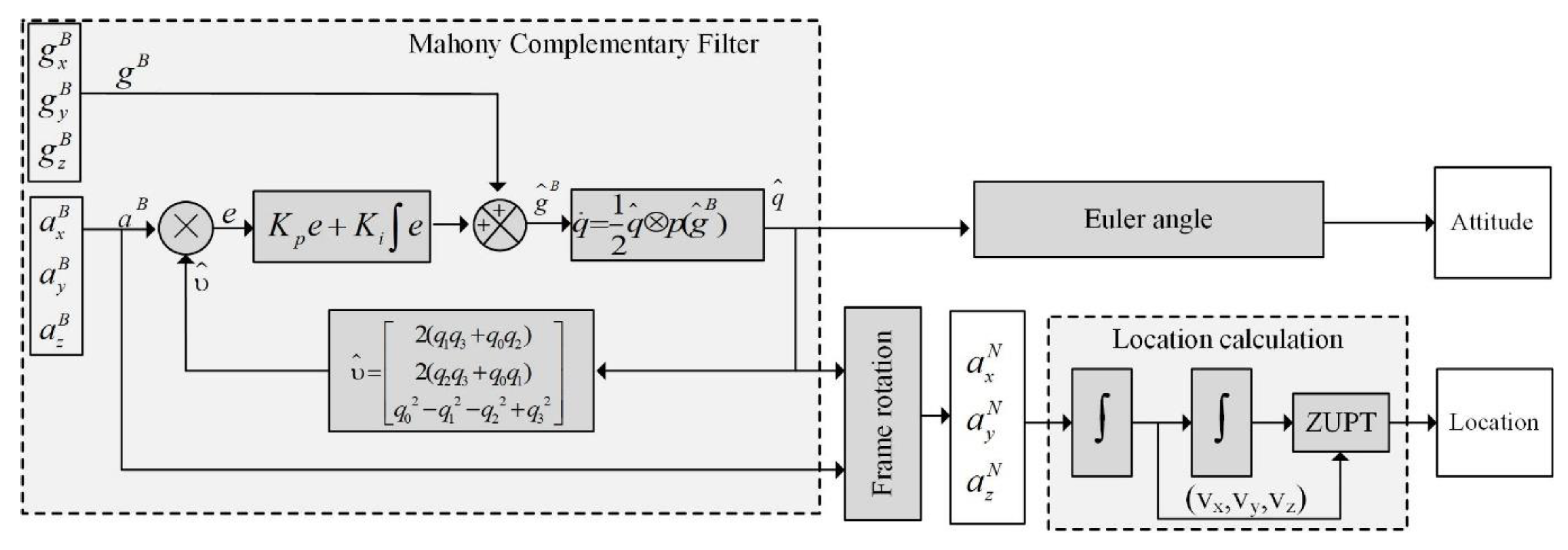
3.2.1. IMU-Based Position Estimation with a Kalman Filter

Suppose the sampling interval is Δ t , p k 1 denotes the displacement in the X-axis direction at time ( k     1 ) Δ t , and Y I M U _ k 1 denotes the observation value of the IMU X-axis direction at time ( k 1 ) Δ t . An observation model is shown in Equation (10):
Y I M U _ k 1   =   p k 1   +   R I M U ,
where R I M U represents the displacement error of the IMU X-axis direction, and R I M U is obtained via statistical methods using a large number IMU observation samples. It is noted that the speed of the X-axis direction at time ( k   1 ) Δ t is v k 1 , and the acceleration is a x N . The equations for motion with uniform acceleration are given as follows:
p k   =   p k 1   +   v k 1   Δ t   +   0.5 ( Δ t ) 2 a x N ,
  v k   =   v k 1   +   Δ t a x N .  
At the time ( k 1 ) Δ t , the state variable x k 1 is the displacement and speed in the X-axis direction:
x k 1   =   [ p k 1 v k 1 ] .
The equation of state can be obtained with:
[ p k v k ]   =   [ 1 Δ t 0 1 ] [ p k 1 v k 1 ]   +   [ 0.5 Δ t 2 Δ t ] a x N .
The observation equation of IMU is:
Y I M U _ k 1 = [ 1 0 ] [ p k 1 v k 1 ] +   R I M U .
Therefore, the state space model can be given with Equations (16) and (17):
x k   =   A x k 1   +   B a x N ,
  Y I M U _ k 1   =   H x k 1 +   R I M U ,
where A   = [ 1 Δ t 0 1 ] ,   B   = [ 0.5 Δ t 2 Δ t ] ,   and   H   =   [ 1 0 ] .

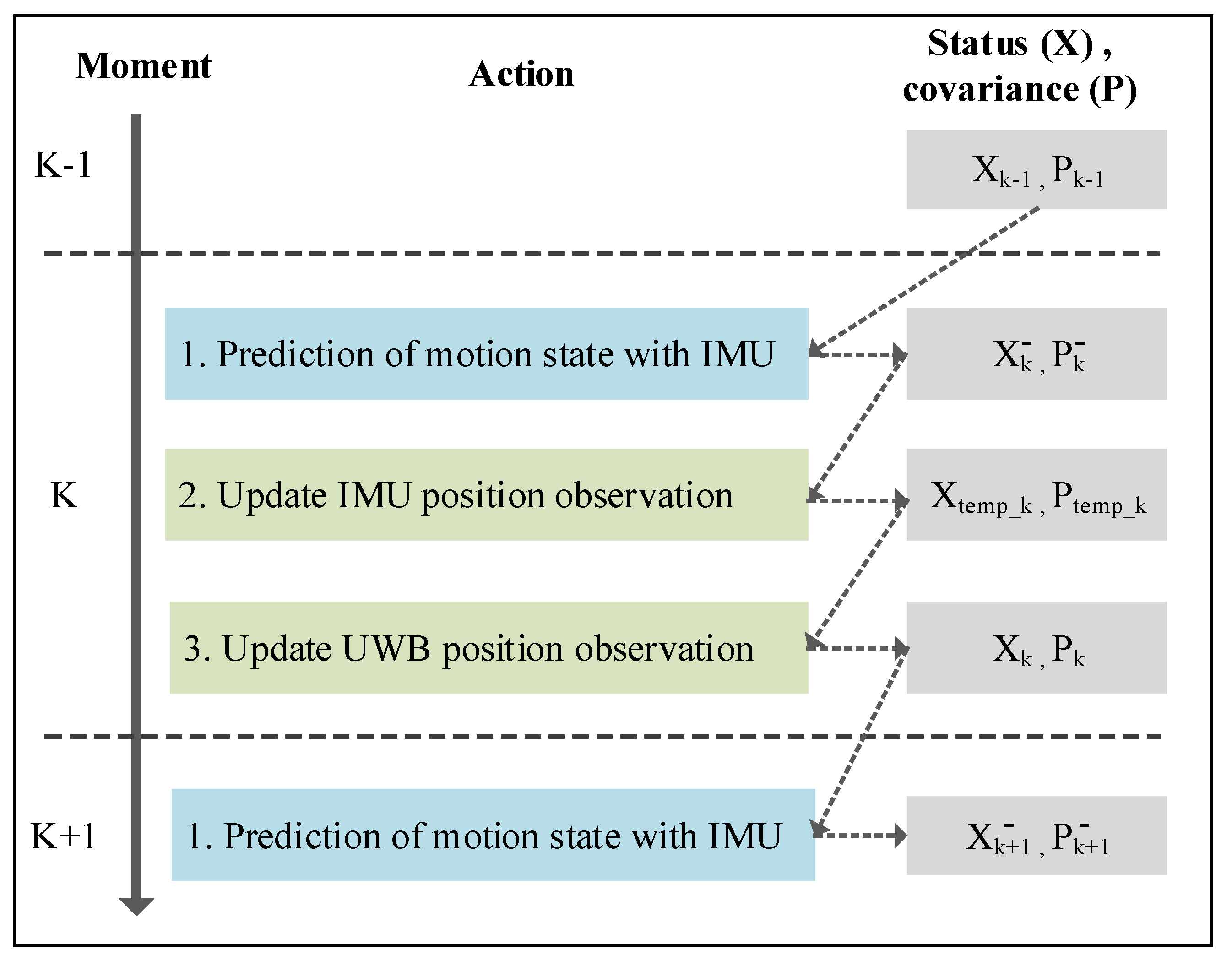
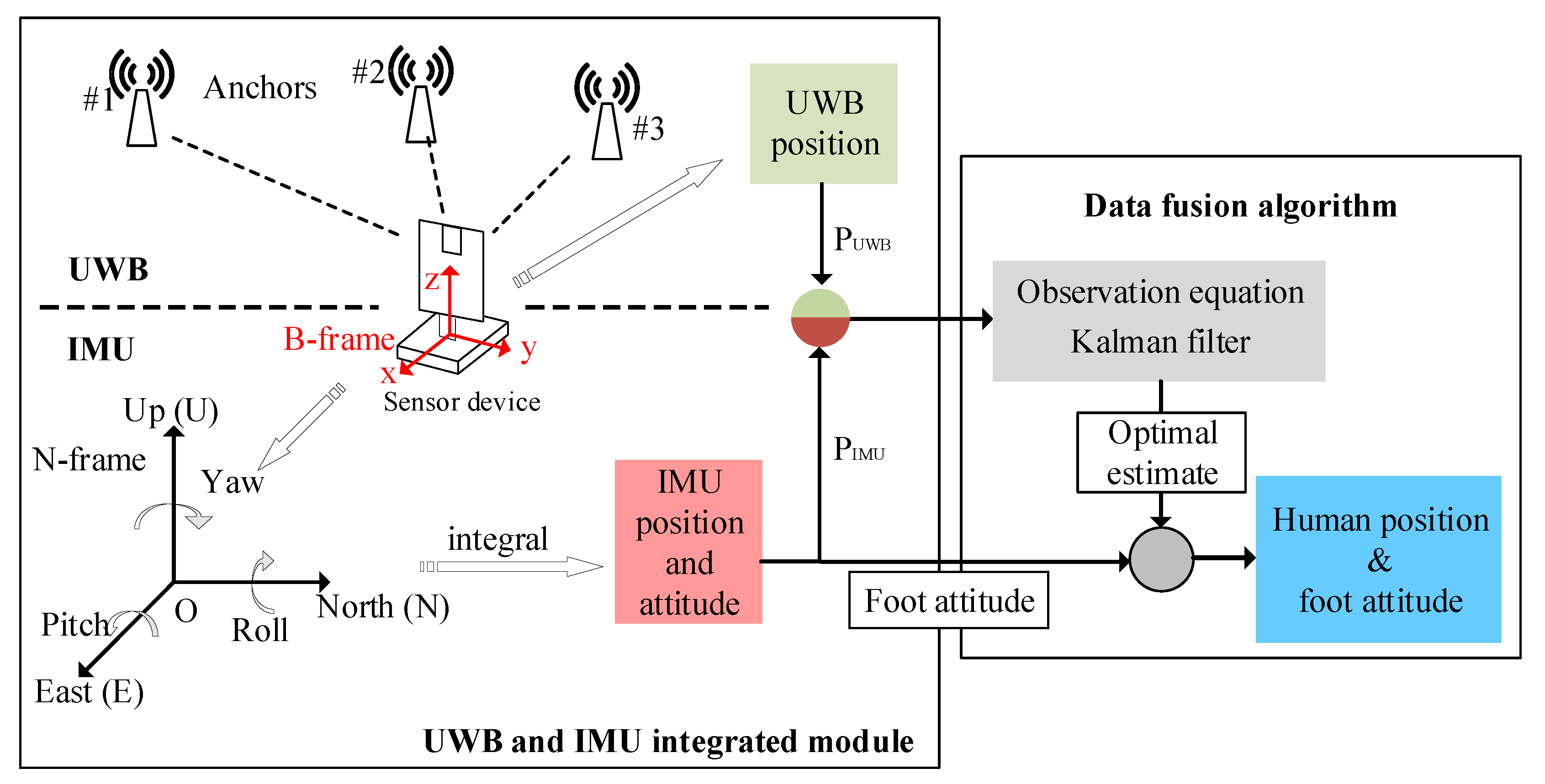
3.2.2. UWB-IMU Data Fusion Model

In this section, we integrate the position data obtained by the UWB and IMU. The position data of the IMU is obtained using integral calculation. The IMU calculation is relatively reliable for a short period, but its error accumulates over time. The UWB positioning may cause deviations due to problems, such as clock skew between the anchor and the tag. However, the measurement results do not drift over time. Therefore, we use the Kalman filter algorithm to integrate the two methods by using an iterative compensation of the two location results, and thereby achieve higher precision indoor positioning.
The data fusion model is shown in Figure 6.
Figure 6. The data fusion process.
Based on the IMU observation data ( Y I M U _ 1   , Y I M U _ 2   , …, Y I M U _ k ), the estimation of the pedestrian X-axis direction displacement p k can be obtained, and the calculation process is as follows.
(1) The current state is estimated based on the previous state using:
x k   =   A x k 1   +   B a x N ,
where x k 1 is the optimal estimation from the previous state and x k is the prediction of the current state.
(2) Calculation of the system covariance is done using:
P k   =   A p k 1 A T + Q ,
where p k 1 is the covariance matrix of the estimated value x k 1   and P k is the covariance of x k   . The Q matrix is the covariance of the motion model and it represents the error between the prediction model and the actual motion. The prediction model of this system is a non-uniformly accelerated motion. In a short interval, the interference caused by other influencing factors, including friction resistance and air resistance, is relatively small. The values of matrix Q are [ 0.1 0 0 0.1 ] .
(3) The Kalman gain transfer coefficient is updated using:
K t e m p _ k   =   P k H T ( H P k H T + R I M U ) 1 .
(4) The transfer status is updated using:
x t e m p _ k   =   x k + K t e m p _ k ( Y I M U _ k 1 H x k ) .
(5) The transfer state covariance matrix is updated using:
P t e m p _ k   =   ( I K t e m p _ k H ) P k .
After updating the IMU observation equation, the state quantity x t e m p _ k and the covariance matrix P t e m p _ k of the IMU system at time k are obtained. The state estimation based on the IMU observation data is used as the prediction quantity in the UWB system, combined with the observations in the UWB system, to get the best position estimate. The state quantity x t e m p _ k and the covariance matrix P t e m p _ k of the IMU system are taken as the UWB system prediction state quantity x k and the system prediction covariance matrix P k make a status update, which are calculated as follows.
(6) The Kalman gain is updated using:
K k   =   P t e m p _ k H T ( H P t e m p _ k H T + R U W B ) 1 ,
where R U W B represents the UWB X-axis direction displacement error (observation noise), and R U W B is obtained via statistical methods using a large number of UWB observation test data.
(7) The status is updated using:
x k   =   x t e m p _ k   +   K k ( Y U W B _ k 1 H   x t e m p _ k ) ,
where Y U W B k 1 represents the observed value of UWB localization at time k − 1.
(8) The state covariance matrix is updated using:
P k   =   ( I     K k H ) P t e m p _ k .
The state quantity x k and the covariance matrix P k of the system obtained after the UWB update are used as the fused output, and the two are used for the prediction process for the next iteration.

3.3. Hardware Design and Data Synchronization

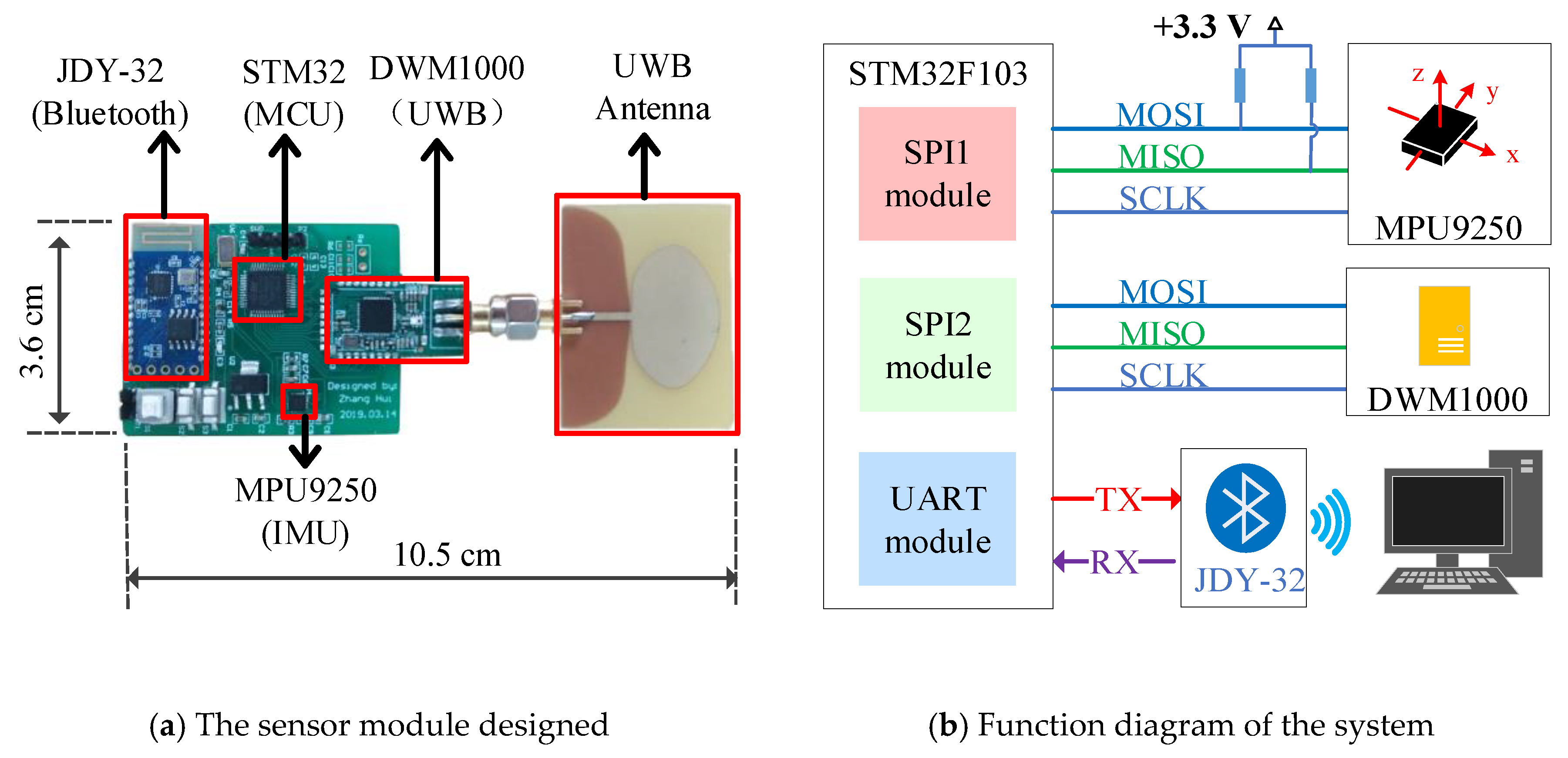
3.3.1. Hardware Design

The integrated UWB and IMU positioning sensor module was designed with a STM32 (STM32F103C8T6, STMicroelectronics, Switzerland) micro control unit MCU as the central controller. The hardware circuit of the system included a STM32 MCU, a DWM1000 UWB module (DWM1000, Decawave, Ireland), a MPU9250 IMU (MPU9250, Invensense, USA), a JDY-32 Bluetooth module (JDY-32, Risym, China), and DC–DC module for the power supply. The designed sensor device and its functional diagrams are as shown in Figure 7a,b.
Figure 7. The UWB-IMU sensor module.
The DWM1000 is an ultra-wide band wireless module from DecaWave that complies with the IEEE802.15.4-2011 standard. In this system, the DWM1000 is responsible for marking the information transmission and reception time stamps and the communication between the base station tags and the sensor tag. The tag uses a polling method to communicate with the base station to complete the ranging function. The MPU9250 is a MEMS IMU module with a gyroscope, an accelerometer, and a magnetometer inside, which can measure the three-axis angular velocity, three-axis acceleration, and three-axis magnetic field. In this system, the acceleration and angular velocity of the sensor device are obtained using the MPU9250, and the corresponding displacement is used to complete the localization functions. Each time the DWM1000 and MPU9250 complete a set of data acquisition and calculations, the sensor device completes the calculation of the IMU position and the data fusion of the two sensing modules, and then sends the results to the host computer through Bluetooth. The host computer records the uploaded data and displays the graphics accordingly.

3.3.2. Synchronized Processing for IMU and UWB Signals

The synchronized data collection and processing of the two sensing modules is critical to the designed sensor device. When a motion is detected by the sensor device, the UWB obtains the displacement data via the DS-TWR method, and the angular velocity and acceleration from the IMU can be calculated to obtain the displacement and attitude. However, the displacement value calculated using the two sensors have certain deviations from the true value, so we compensate the two sets of data through a Kalman filter to obtain an optimal estimation of the displacement, which were presented in Section 3.2.2. The measured values of the two sets of sensors are used as inputs for the Kalman filter, which is used to find the positioning data closest to the true value. Finally, the optimal position estimate and attitude variation of the current time for the sensor device are obtained. The functional diagram is shown in Figure 8.
Figure 8. Synchronized processing for the UWB and IMU signals.

4. Experimental Verification and Results Analysis

In order to verify the feasibility and effectiveness of the proposed solutions in terms of both hardware and algorithm, we implemented the data processing algorithm with the designed sensor device. The data was collected through Bluetooth with a host PC recording and displaying the results using a MATLAB (R2016b, MathWorks, USA) graphical interface. Practical experiments of one-step walking, arbitrary path continuous walking, and abnormal gait detection were conducted for evaluating the proposed solution.

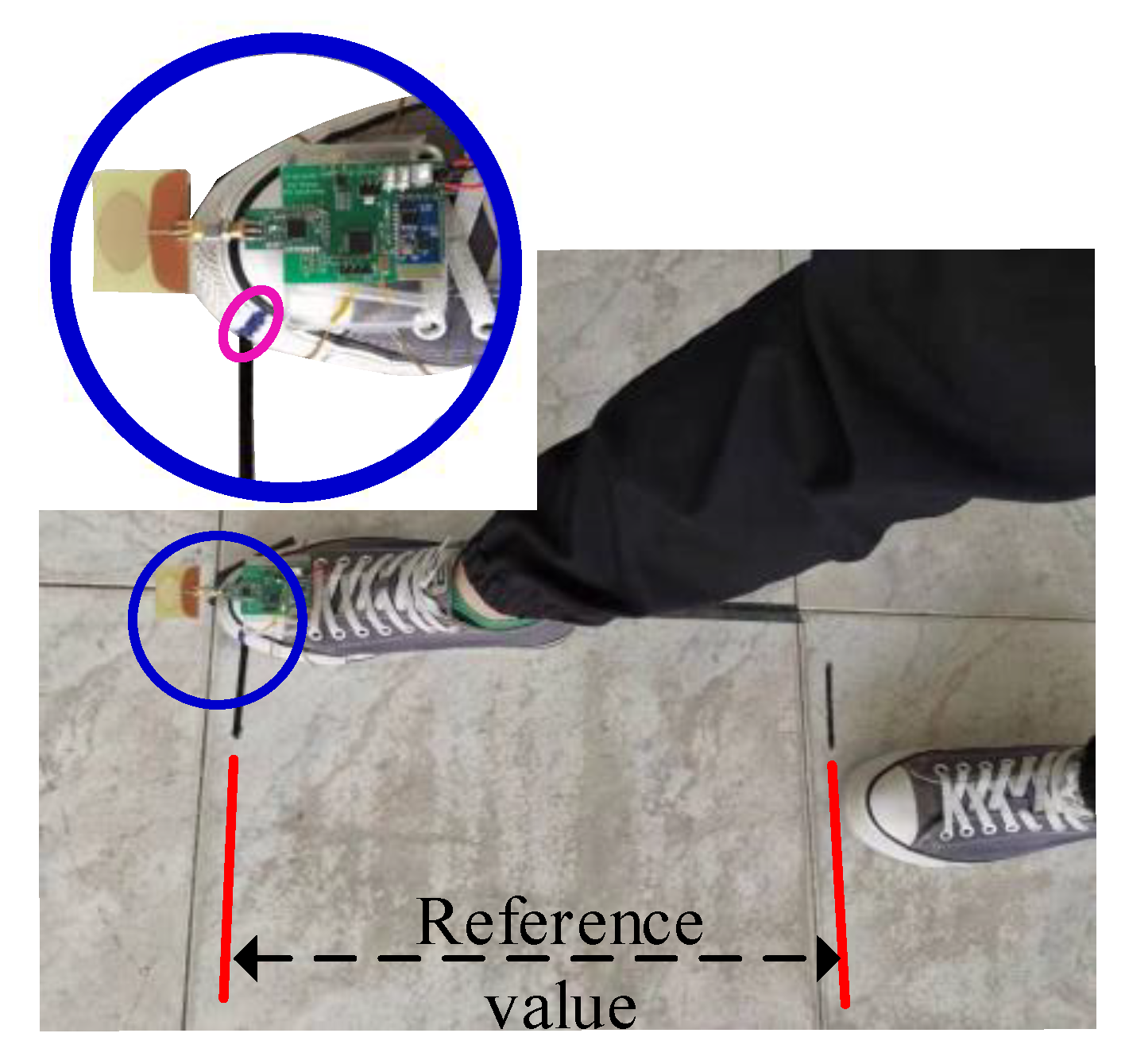
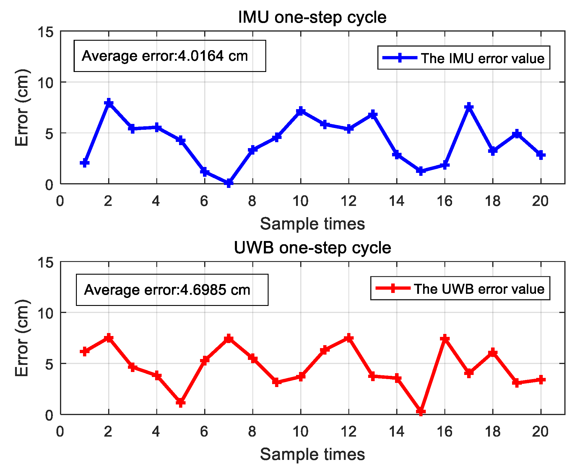
4.1. Measurement of One-Step Walking

In this section, the positioning accuracy of the IMU module and the UWB module are evaluated. The sensor device was fixed on the surface of the foot and a one-step walking was performed 20 times to measure the step size. The experimental setup is shown in Figure 9. In order to obtain the walking distance, a marker point was made on the experimenter’s shoes, which is highlighted with the pink circle in Figure 9. The relative position of the marker point was used as a benchmark to obtain the displacement. The measurement results of the two modules for 20 repeated one-step walking events are given in Figure 10. The average errors of the IMU module and UWB module were 4.02 cm and 4.70 cm, respectively. Figure 11 shows the measured acceleration, velocity, and displacement during a one-step walking event with the IMU module.
Figure 9. Displacement of one-step walking.
Figure 10. Errors of the 20 repeated walking steps.
Figure 11. The acceleration, velocity, and displacement of one-step walking.

4.2. Rectangular and Arbitrary Path Continuous Walking

4.2.1. Experimental Setup

A meeting room sized 7.0 × 5.5 m including a few pieces of furniture was chosen as the indoor experimental scene for the further experimental studies, and the diagram of the room is shown in Figure 12a. In order to verify the localization accuracy of the fusion method with a Kalman filter by making use of the two sets of sensing data, experiments of walking along a rectangular path and an arbitrary path in an indoor environment were carried out. For the arbitrary path, it can be set to be much more complicated. However, the small corners in the complicated trajectory may be difficult to follow for the experimenter and large errors may be introduced. As shown in Figure 12, the black tape on the floor shows the paths for the experimenter to walk along. The initial position of the sensor device was defined the origin (0,0).
Figure 12. Indoor experimental scene and the experimental setup.

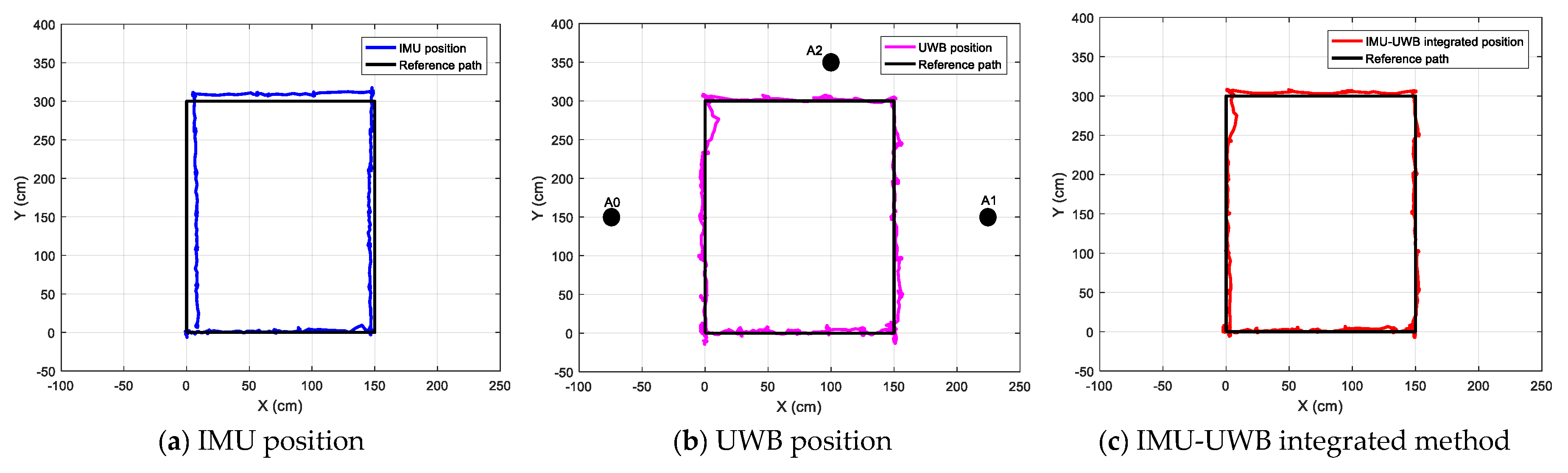
4.2.2. Tests with a Rectangular Path

By walking around the rectangular path once, the IMU-measured location, UWB-measured location, and fusion results are given in Figure 13. From the results, it is easy to find that:
Figure 13. The measured locations for walking along a rectangular path.
(1)
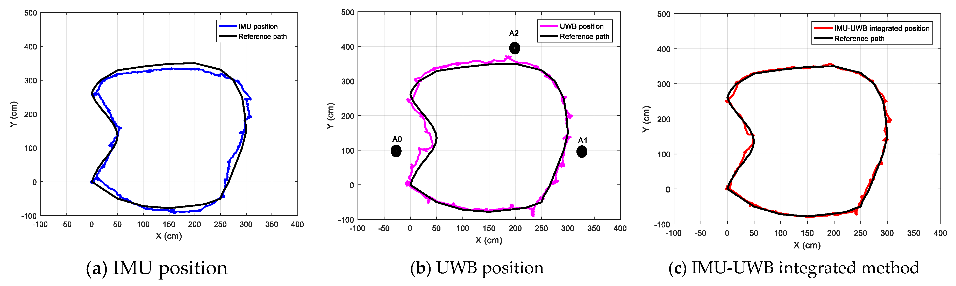
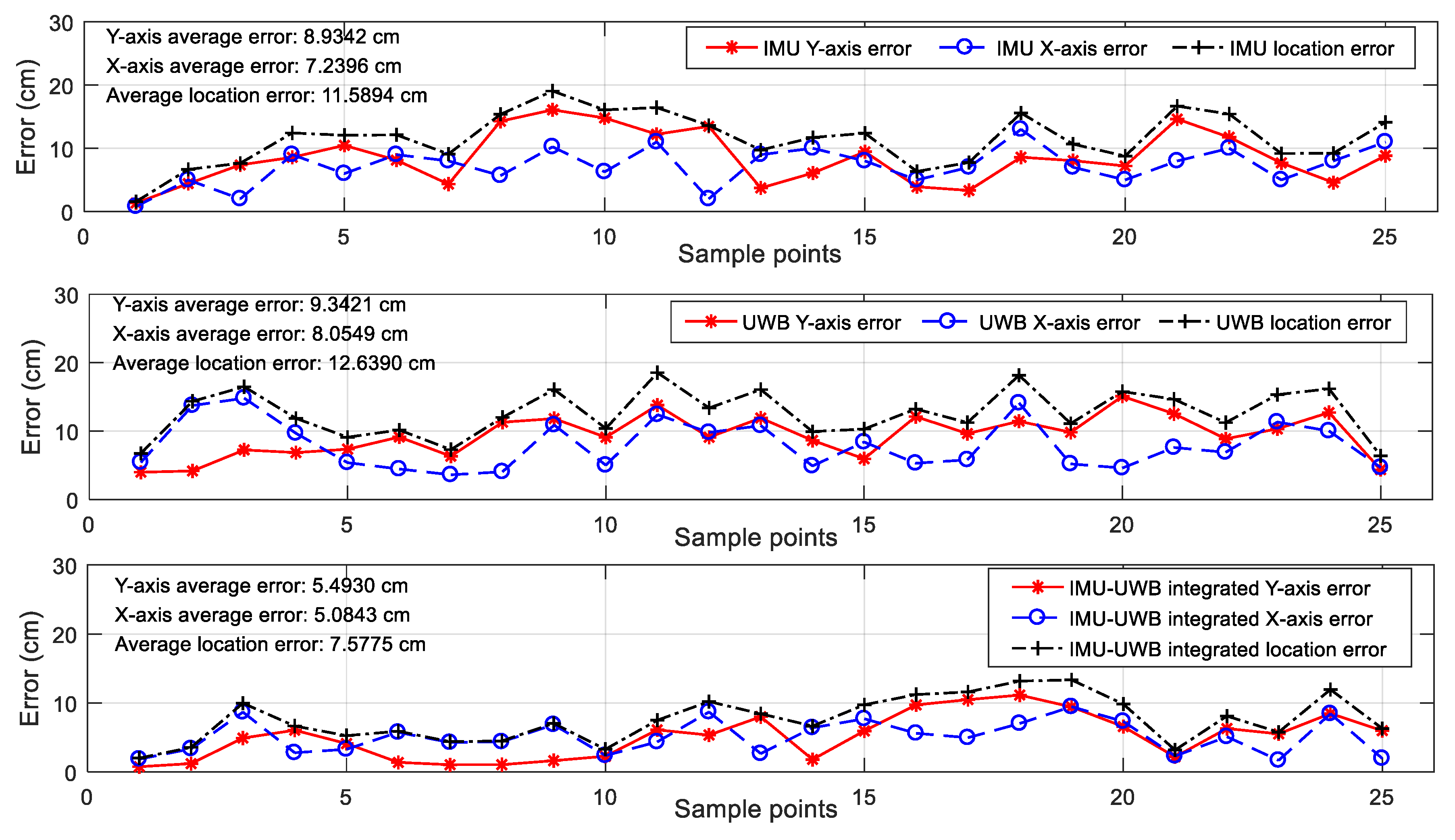
For the IMU measurement, there was an evident systemic error, as seen by the deviation between the black and blue lines in Figure 13a, which was hard to correct by the module itself. This was because the current location was calculated by integrating the variations of previous moments. However, the location was relatively stable and the error for one single step is not evident.
(2)
For the UWB system, it was susceptible to NLoS occlusion of experimenter’s ankles, resulting in a bias error. As shown in Figure 13b, the positioning error caused by NLoS appeared multiple times in the UWB positioning results, and the error in the upper-left corner was significant. Although the localization accuracy was competitive for indoor applications, the results were not stable since the UWB radio was susceptible to ambient interferences.
(3)
For the UWB-IMU integrated system, the advantages of the above two systems were combined. The UWB data was used to compensate for the inertial localization, and the inertial data was used to correct the UWB positioning data to make it more stable. The two sets of displacement data were iteratively compensated by the fusion algorithm, and as shown in Figure 13c, the final localization results were more accurate and stable.

4.2.3. Tests with an Arbitrary Path

For the arbitrary walking path, the location was obtained by marking the position of the foot, which is shown in Figure 9. The measured displacement was recorded by marking the foot positions for each step, and the measured values of the three methods by the sensor device were recorded and transmitted through Bluetooth to a host PC for evaluation and analysis. The final results are given in the figures below. Figure 14a–c show the measurement results of the three methods for the arbitrary path walking, and Figure 15 gives the X-axis, Y-axis, and overall position error between the measured value and the object positions for the three methods, respectively. From the test results, it is easy to find that: (1) the IMU localization suffered from a systemic error, and the low-cost IMU device could hardly obtain a high accuracy; (2) the UWB localization values were not stable due to sensitive radio wave signals; and (3) the UWB-IMU integrated method improved the localization performance in terms of both stability and accuracy. From Figure 15, the average position error ( x 2 + y 2 ) of the IMU-UWB integrated method was 7.58 cm, which was significantly improved compared to 11.59 cm and 12.64 cm for the methods with IMU and UWB only.
Figure 14. The measured locations for walking along an arbitrary path.
Figure 15. The measurement errors of the three methods.

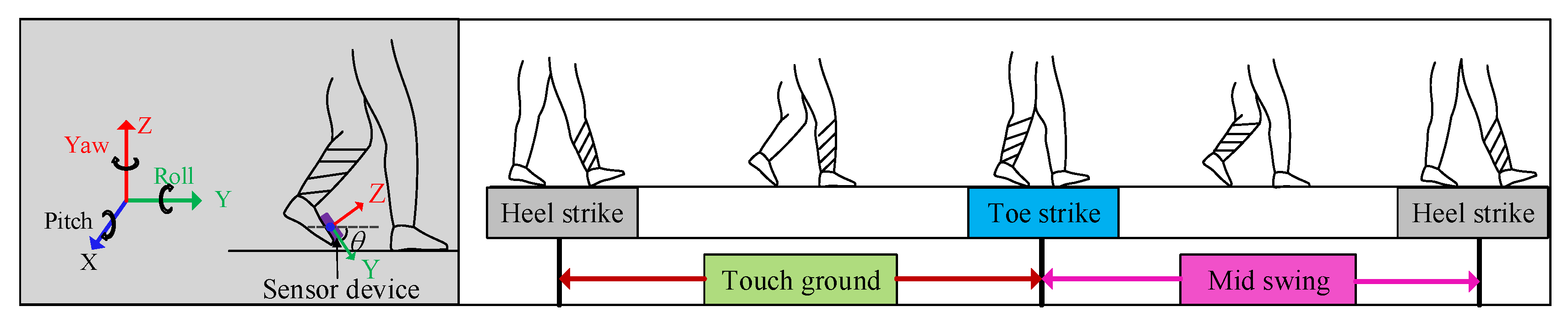
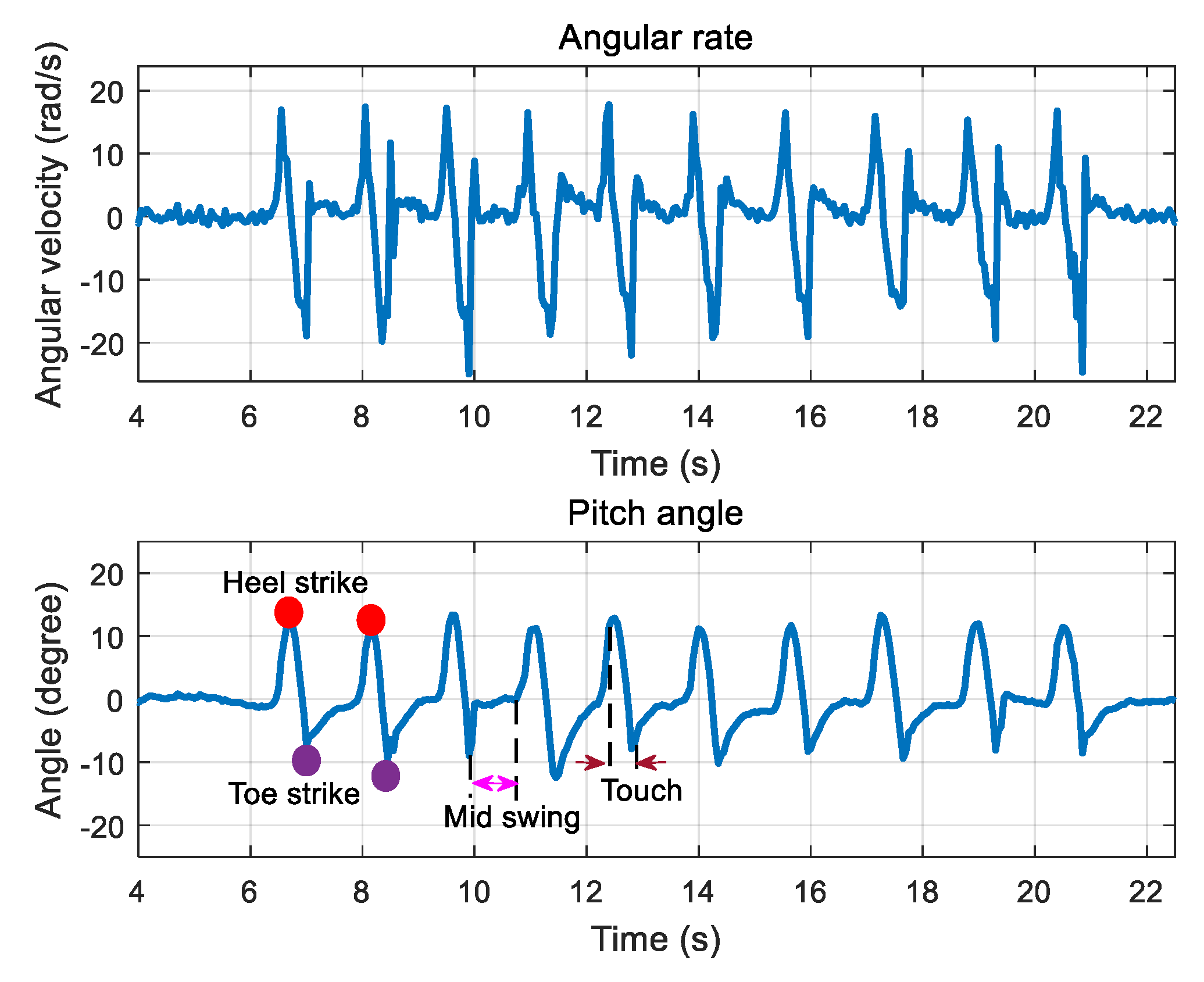
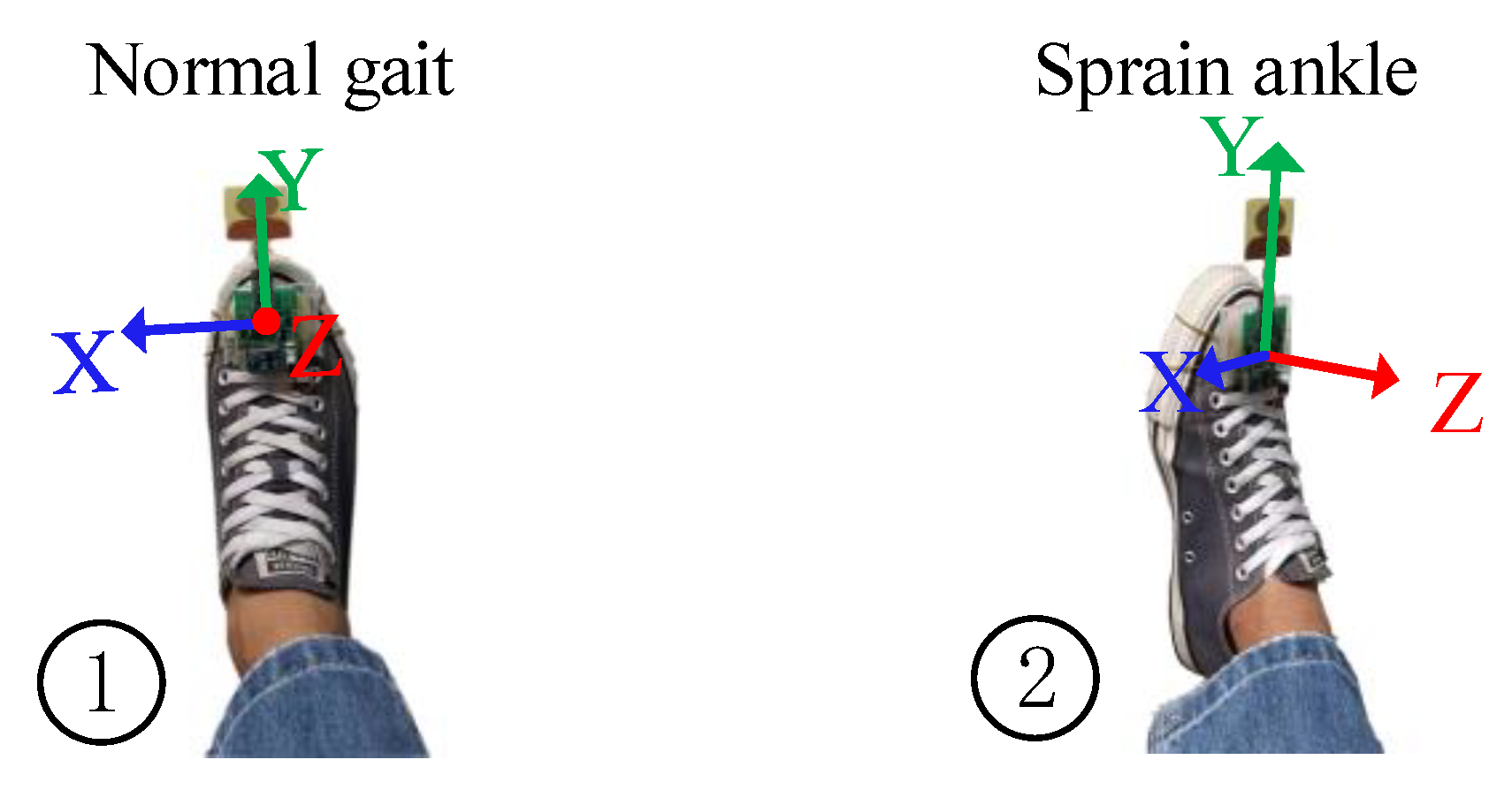
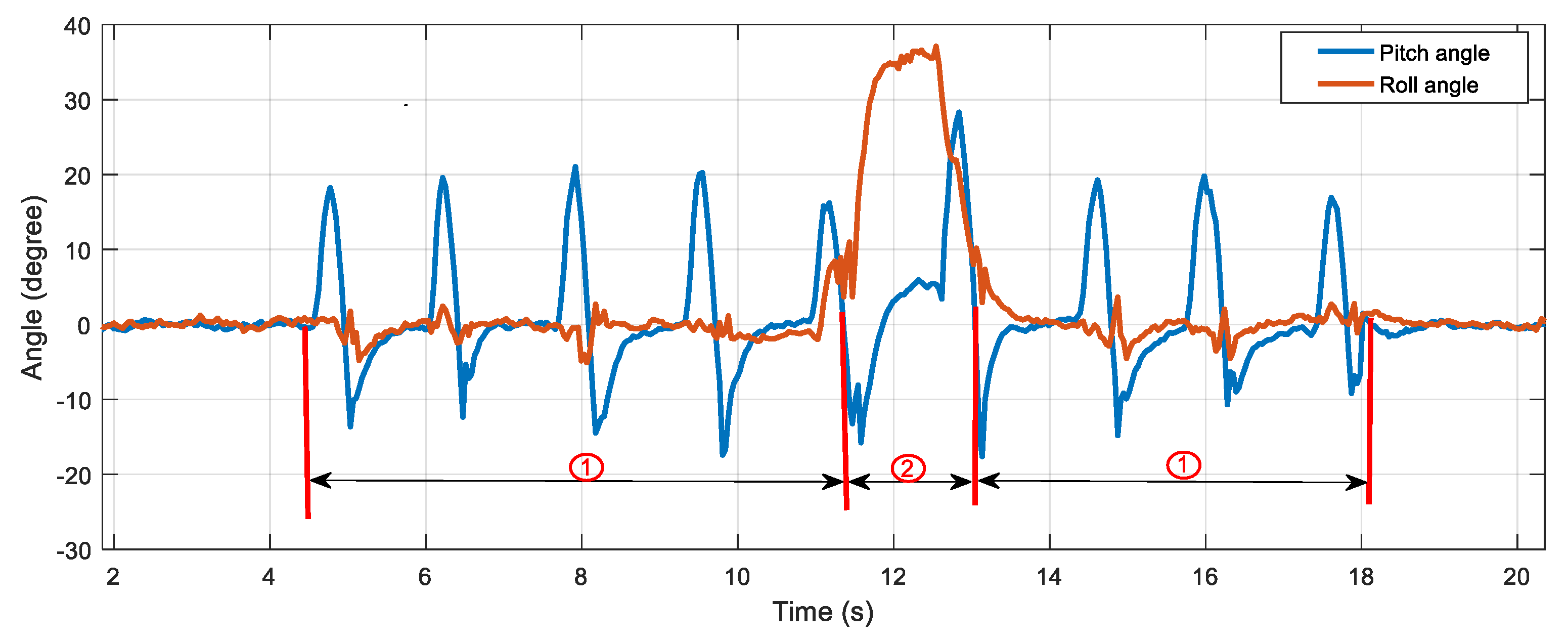
4.3. Real-Time Attitude Measurement for Gait Analysis

In addition to the indoor localization, the sensor device can also measure the attitude variation of the pedestrian’s foot during the walk. Since walking is a very common form of activity in human daily activities, it is a very important indicator for clinical rehabilitation. The gait shows how people walk and exhibit gait patterns that change periodically. A standard gait cycle can be divided into four phases, namely heel strikes on the ground, touching the ground, the toes touch the ground, and swinging, which are shown in Figure 16. In this system, we fixed the sensor device on the surface of foot to obtain the angle of the foot, namely the change of θ in Figure 16. As shown in Figure 17, the test results demonstrate that the change of the pitch angle in the normal gait period coincided with the actual changes in the posture of the foot surface.
Figure 16. One gait cycle.
Figure 17. Measurement of foot attitude with the developed sensor device.
In order to prove the usability of measuring the angles for gait analysis, a test of simulated foot twisting during walking was performed, which is shown in Figure 18. When the sensor device was fixed to the surface of the foot and the foot twisting occurred, the abnormal actions (the foot twisting or falling) could be recognized by analyzing the roll angle. As shown in Figure 18, the roll angle fluctuated in a small range around zero degrees during normal walking and deviated from the normal threshold range once the abnormal foot action occurred.
Figure 18. Normal and abnormal foot actions.
The results shown in Figure 19 demonstrate the potentiality of the developed sensor device for real-time gait analysis, which is of interest to many IoT applications.
Figure 19. Measurement of abnormal foot attitude.

5. Discussion

By integrating the UWB and IMU with the proposed hardware and data fusion solutions, the UWB-IMU sensing module takes the advantages of the high-accuracy UWB localization and IMU localization signal stability, robust NLoS localization, and capability for motion tracking. Through the design and implementation in this investigation, the lessons learned are summarized as follows:
(1)
For the IMU measurement, it was evident that the inertial measurement suffered from error accumulation although a ZUPT algorithm was implemented. The accumulated error finally turned to a system error in the inflection points, which decreased the accuracy of the final results. The possible solutions for correcting this system error might be to identify the inflection point and correct the inertial measurement result with a UWB measurement. This method may be able to effectively reduce the IMU accumulation error in the inflection point and promote the accuracy of localization results.
(2)
The UWB measurement showed evident random errors, and there was also evident greater measurement errors when there was a NLoS occlusion between the sensor node and the UWB anchors. Being incapable of dealing with this error resulted in a lower localization accuracy. The promising solution to handle this error is to observe the gradient of the UWB location and IMU location and determine the emergence of barriers and correct the error by adjusting the trust weight of the UWB and IMU results.
Since indoor localization has attracted widespread interest in recent years, more accurate wearable modules and the corresponding algorithms are focal research topics. The solutions for the above technical issues may finally result in higher accuracy.

6. Conclusions and Future Work

6.1. Conclusions

This investigation proposed cost-effective hardware and data fusion solutions for the integration of UWB and IMU in a wearable module for human indoor localization and motion tracking. The Mahony filter and quaternions were employed for attitude estimation using the accelerometer and gyroscope, and the accelerations in the navigation coordinates were obtained to calculate the variations of location. UWB and IMU locations were integrated with a data fusion model based on a Kalman filter to obtain the final results. With these techniques, the designed module achieved the indoor localization and motion tracking goals. The UWB-IMU integrated solution takes the advantage of both the high-accuracy UWB localization and the IMU localization signal stability, robust NLoS localization, and motion tracking capability. Since the module is compact in size and is battery powered, it is a competitive alternative for many wearable indoor localization applications, such as elderly care, sport motion analysis, rehabilitation medicine, and robot navigation.

6.2. Future Work

It was found that the UWB error caused by NLoS blocking by human body parts between the UWB anchor and sensor node had a critical influence on the measurement, and the accumulated error of the IMU measurement was another critical error. The future work will focus on seeking solutions for minimizing the errors, including:
(1)
A smart algorithm to automatically identify the NLoS blocking errors and adjust the weight of trust between the UWB results and IMU results to improve the localization accuracy.
(2)
The determination of the key turning corners in the motion where the IMU results may introduce errors and use the UWB location to correct the accumulated error of IMU localization results.
(3)
Comprehensive evaluation of the designed IMU-UWB system by comparing the estimation with more reliable references using methods such as the Cramer–Rao low bound (CRLB).
(4)
Evaluation of the influence caused by indoor environment including human body and furniture, such as the error caused by the random walking pedestrians and their walking speed.
In addition, to extend the UWB-IMU measurement from indoor localization to building-scale localization and navigation for product and human tracking is a promising field. Undoubtedly, there has been a great need for indoor localization for human tracking and motion analysis. A smart wearable sensor device that is more accurate, reliable, and easy-to-use for indoor localization is of interest to many novel IoT applications in the future rich-sensing smart world.

Author Contributions

Conceptualization, H.Z. and Z.M.; methodology, Z.M.; software, H.Z.; validation, H.Z. and Z.M.; writing—original draft preparation, H.Z.; writing—review and editing, H.Z. and Z.M.; visualization, Z.L.; supervision, Z.Z., N.G., and Y.X.; project administration, Z.M.; funding acquisition, Z.M. All authors have read and agreed to the published version of the manuscript.

Funding

This research was funded by the National Natural Science Foundation of China (NSFC) (grant number 51805143), the Introduced Overseas High-Level Talents Project (E2019050014), the Natural Science Foundation of Hebei Province (grant number E2019202131), and the Introduced Overseas Talent Supporting Project of Hebei Province (grant number C20190324).

Acknowledgments

The authors would like to thank the Nondestructive Detection and Monitoring Technology for High Speed Transportation Facilities, Key Laboratory of Ministry of Industry and Information Technology for the technical advice and support.

Conflicts of Interest

The authors declare no conflict of interest.

References

  1. He, S.; Chan, S.H.G. Wi-Fi fingerprint-based indoor positioning: Recent advances and comparisons. IEEE Commun. Surv. Tutor. 2016, 18, 466–490. [Google Scholar] [CrossRef]
  2. Jo, H.J.; Kim, S. Indoor Smartphone Localization Based on LOS and NLOS Identification. Sensors 2018, 18, 3987. [Google Scholar] [CrossRef] [PubMed]
  3. Kwon, Y.; Kwon, K. RSS ranging based indoor localization in ultra low power wireless network. AEU Int. J. Electron. Commun. 2019, 104, 108–118. [Google Scholar] [CrossRef]
  4. Wu, C.; Yang, Z.; Liu, Y. Smartphones Based Crowdsourcing for Indoor Localization. IEEE Trans. Mob. Comput. 2015, 14, 444–457. [Google Scholar] [CrossRef]
  5. Zhang, G.; Wang, P.; Chen, H.; Zhang, L. Wireless Indoor Localization Using Convolutional Neural Network and Gaussian Process Regression. Sensors 2019, 19, 2508. [Google Scholar] [CrossRef]
  6. Luo, R.C.; Hsiao, T.J. Dynamic Wireless Indoor Localization Incorporating with an Autonomous Mobile Robot Based on an Adaptive Signal Model Fingerprinting Approach. IEEE Trans. Ind. Electron. 2018, 66, 1940–1951. [Google Scholar] [CrossRef]
  7. Yang, X.; Zhao, F.; Chen, T. NLOS identification for UWB localization based on import vector machine. AEU Int. J. Electron. Commun. 2018, 87, 128–133. [Google Scholar] [CrossRef]
  8. Alrajeh, N.A.; Bashir, M.; Shams, B. Localization techniques in wireless sensor networks. Int. J. Distrib. Sens. Netw. 2013, 9, 304628. [Google Scholar] [CrossRef]
  9. Dardari, D.; Closas, P.; Djuric, P.M. Indoor Tracking: Theory, Methods, and Technologies. IEEE Trans. Veh. Technol. 2015, 64, 1263–1278. [Google Scholar] [CrossRef]
  10. Robert, M.; Tarek, H.; Jean-Michel, P. Nonlinear complementary filters on the special orthogonal group. IEEE Trans. Autom. Control 2008, 53, 1203–1217. [Google Scholar]
  11. Wan, E.A.; Van der Merwe, R. The Unscented Kalman Filter for Nonlinear Estimation. In Proceedings of the IEEE 2000 Adaptive Systems for Signal Processing, Communications, and Control Symposium, Lake Louise, AB, Canada, 4 October 2000. [Google Scholar]
  12. Wang, Y.; Rajamani, R. Direct cosine matrix estimation with an inertial measurement unit. Mech. Syst. Signal Process. 2018, 109, 268–284. [Google Scholar] [CrossRef]
  13. Liu, M.; Lai, J.; Li, Z.; Liu, J. An adaptive cubature Kalman filter algorithm for inertial and land-based navigation system. Aerosp. Sci. Technol. 2016, 51, 52–60. [Google Scholar] [CrossRef]
  14. Moschas, F.; Stiros, S. Experimental evaluation of the performance of arrays of MEMS accelerometers. Mech. Syst. Signal Process. 2019, 116, 933–942. [Google Scholar] [CrossRef]
  15. Sun, F.; Mao, C.; Fan, X.; Li, Y. Accelerometer-based speed-adaptive gait authentication method for wearable IoT devise. IEEE Internet Things J. 2019, 6, 820–830. [Google Scholar] [CrossRef]
  16. Lin, K.; Chen, M.; Deng, J.; Hassan, M.M.; Fortino, G. Enhanced fingerprinting and trajectory prediction for IoT localization in smart buildings. IEEE Trans. Autom. Sci. Eng. 2016, 13, 1294–1307. [Google Scholar] [CrossRef]
  17. Pasku, V.; Angelis, A.D.; Angelis, G.D.; Arumugam, D.D.; Dionigi, M.; Carbone, P.; Moschitta, A.; Ricketts, D.S. Magnetic field-based positioning system. IEEE Commun. Surv. Tutor. 2017, 19, 2003–2017. [Google Scholar] [CrossRef]
  18. Baronti, P.; Barsocchi, P.; Chessa, S.; Mavilia, F.; Palumbo, F. Indoor Bluetooth low energy dataset for localization, tracking, occupancy, and social interaction. Sensors 2018, 18, 4462. [Google Scholar] [CrossRef]
  19. Luo, C.; Cheng, L.; Chan, M.C.; Gu, Y.; Li, J.; Ming, Z. Pallas: Self-Bootstrapping fine-grained passive indoor localization using WiFi monitors. IEEE Trans. Mob. Comput. 2017, 16, 466–481. [Google Scholar] [CrossRef]
  20. Minne, K.; Macoir, N.; Rossey, J.; Brande, Q.V.D.; Lemey, S.; Hoebeke, J.; Poorter, E.D. Experimental evaluation of UWB indoor positioning for indoor track cycling. Sensors 2019, 19, 2041. [Google Scholar] [CrossRef]
  21. Buffi, A.; Michel, A.; Nepa, P.; Tellini, B. RSSI measurements for RFID tag classification in smart storage systems. IEEE Trans. Instrum. Meas. 2018, 67, 894–904. [Google Scholar] [CrossRef]
  22. Poulose, A.; Eyobu, O.S.; Han, D.S. An indoor position-estimation algorithm using smartphone IMU sensor data. IEEE Access 2019, 7, 11165–11177. [Google Scholar] [CrossRef]
  23. Zegeye, W.K.; Amsalu, S.B.; Astatke, Y.; Moazzami, F. WiFi RSSI Fingerprinting Indoor Localization for Mobile Devices. In Proceedings of the IEEE 7th Annual Ubiquitous Computing, Electronics & Mobile Communication Conference, New York, NY, USA, 20–22 October 2016; pp. 1–6. [Google Scholar]
  24. Shu, Y.; Huang, Y.; Zhang, J.; Coue, P.; Cheng, P.; Chen, J.; Shin, K.G. Gradient-based fingerprinting for indoor localization and tracking. IEEE Trans. Ind. Electron. 2016, 63, 2424–2433. [Google Scholar] [CrossRef]
  25. Zhou, H.; Jin, M.; Jiang, H.; Xie, L.; Spanos, C.J. WinPS: WiFi-based non-intrusive indoor positioning system with online radio map construction and adaptation. IEEE Trans. Wirel. Commun. 2017, 16, 8118–8130. [Google Scholar] [CrossRef]
  26. Sun, W.; Xue, M.; Yu, H.; Tang, H.; Lin, A. Augmentation of fingerprints for indoor WiFi localization based on Gaussian process regression. IEEE Trans. Veh. Technol. 2018, 67, 10896–10905. [Google Scholar] [CrossRef]
  27. Chen, C.; Chen, Y.; Han, Y.; Lai, H.-Q.; Liu, K.J.R. Achieving centimetre-accuracy indoor localization on WiFi platforms: A frequency hopping approach. IEEE Internet Things J. 2017, 4, 111–121. [Google Scholar]
  28. Tao, Y.; Zhao, L. A novel system for WiFi radio map automatic adaptation and indoor positioning. IEEE Trans. Veh. Technol. 2018, 67, 10683–10692. [Google Scholar] [CrossRef]
  29. Saab, S.S.; Nakad, Z. A standalone RFID indoor positioning system using passive tags. IEEE Trans. Ind. Electron. 2011, 58, 1961–1970. [Google Scholar] [CrossRef]
  30. Subedi, S.; Pauls, E.; Zhang, Y.D. Accurate localization and tracking of a passive RFID reader based on RSSI measurement. IEEE J. Radio Freq. Identif. 2017, 1, 144–154. [Google Scholar] [CrossRef]
  31. Wei, D.; Hung, W.; Wu, K.-L. A Real Time RFID Locationing System Using Phased Array Antennas for Warehouse Management. In Proceedings of the 2016 IEEE International Symposium on Antennas and Propagation (APSURSI), Fajardo, Puerto Rico, 26 June–1 July 2016; pp. 1153–1154. [Google Scholar]
  32. DiGiampaolo, E.; Martinelli, F. A robotic system for localization of passive UHF-RFID tagged objects on shelves. IEEE Sens. J. 2018, 18, 8558–8568. [Google Scholar] [CrossRef]
  33. Ma, Y.; Tian, C.; Jiang, Y. A multi-tag cooperative localization algorithm based on weighted multidimensional scaling for passive UHF RFID. IEEE Internet Things J. 2019, 6, 6548–6555. [Google Scholar] [CrossRef]
  34. Wum, H.; Gong, Z.; Yin, Z.; Ding, H. A fast UHF RFID localization method using unwrapped phase-position model. IEEE Trans. Autom. Sci. Eng. 2019, 16, 1698–1707. [Google Scholar]
  35. Shangguan, L.; Yang, Z.; Liu, A.X.; Zhou, Z.; Liu, Y. STPP: Spatial-temporal phase profiling-based method for relative RFID tag localization. IEEE ACM Trans. Netw. 2017, 25, 596–609. [Google Scholar] [CrossRef]
  36. Halder, S.; Ghosal, A. A survey on mobility-assisted localization techniques in wireless sensor networks. J. Netw. Comput. Appl. 2016, 60, 82–94. [Google Scholar] [CrossRef]
  37. Oguntala, G.; Abd-Alhmeed, R.; Jones, S.; Noras, J.; Patwary, M.; Rodriguez, J. Indoor location identification technologies for real-time IoT-based applications: An inclusive survey. Comput. Sci. Rev. 2018, 30, 55–79. [Google Scholar] [CrossRef]
  38. Gezici, S.; Tian, Z.; Giannakis, G.B.; Kobayashi, H.; Molisch, A.F.; Poor, H.V.; Sahinoglu, Z. Localization via Ultra-wideband radios: A look at positioning aspects for future sensor networks. IEEE Signal Proc. Mag. 2005, 22, 70–84. [Google Scholar] [CrossRef]
  39. Ridolfi, M.; Vandermeeren, S.; Defraye, J.; Steendam, H.; Gerlo, J.; Clercq, D.D.; Hoebeke, J.; Poorter, E.D. Experimental evaluation of UWB indoor positioning for support postures. Sensors 2018, 18, 168. [Google Scholar] [CrossRef]
  40. Yang, X. NLOS mitigation for UWB localization based on sparse pseudo-input Gaussian process. IEEE Sens. J. 2018, 18, 4311–4316. [Google Scholar] [CrossRef]
  41. Xu, Y.; Shmaliy, Y.S.; Ahn, C.K.; Tian, G.; Chen, X. Robust and accurate UWB-based indoor robot localization using integrated EKF/EFIR filtering. IET Radar Sonar Nav. 2018, 12, 750–756. [Google Scholar] [CrossRef]
  42. Yuan, Q.; Chen, I.M. Localization and velocity tracking of human via 3IMU sensors. Sens. Actuators A Phys. 2014, 212, 25–33. [Google Scholar] [CrossRef]
  43. Kyritsis, K.; Diou, C.; Delopoulos, A. Modeling wrist micromovements to measure in-meal eating behavior from inertial sensor data. IEEE J. Biomed. Health 2019, 23, 2325–2334. [Google Scholar] [CrossRef]
  44. Mazomenos, E.B.; Biswas, D.; Cranny, A.; Rajan, A.; Maharatna, K.; Achner, J.; Klemke, J.; Jöbges, M.; Ortmann, S.; Langendörfer, P. Detecting elementary arm movements by tracking upper limb joint angles with MARG sensors. IEEE J. Biomed. Health 2016, 20, 1088–1099. [Google Scholar] [CrossRef] [PubMed]
  45. Zhang, R.; Höflinger, F.; Reindl, L. Inertial sensor based indoor localization and monitoring system for emergency responders. IEEE Sens. J. 2013, 13, 838–848. [Google Scholar] [CrossRef]
  46. Zheng, L.; Zhou, W.; Tang, W.; Zheng, X.; Peng, A.; Zheng, H. A 3D indoor positioning system based on low-cost MEMS sensors. Simul. Model. Pract. Theory 2016, 65, 45–56. [Google Scholar] [CrossRef]
  47. Corrales, J.A.; Candelas, F.; Torres, F. Hybrid Tracking of Human Operators Using IMU/UWB Data Fusion by a Kalman Filter. In Proceedings of the 2008 3rd ACM/IEEE International Conference on Human-Robot Interaction (HRI), Amsterdam, The Netherlands, 12–15 March 2008; pp. 193–200. [Google Scholar]
  48. Wang, Y.; Li, X. The IMU/UWB fusion positioning algorithm based on Particle filter. ISPRS Int. J. Geo Inf. 2017, 6, 235. [Google Scholar] [CrossRef]
  49. Sasiadek, J.Z.; Hartana, P. GPS/INS sensor fusion for accurate positioning and navigation based on Kalman filtering. IFAC Proc. Vol. 2004, 37, 115–120. [Google Scholar] [CrossRef]
  50. Murata, M.; Ahmetovic, D.; Sato, D.; Takagi, H.; Kitani, K.M.; Asakawa, C. Smartphone-based localization for blind navigation in building-scale indoor environments. Pervasive Mob. Comput. 2019, 57, 14–32. [Google Scholar] [CrossRef]
  51. Jiang, C.; Fahad, M.; Guo, Y.; Chen, Y. Robot-assisted smartphone localization for human indoor tracking. Robot Auton. Syst. 2018, 106, 82–94. [Google Scholar] [CrossRef]
  52. Zhang, P.; Zhao, Q.; Niu, X.; Zhuang, Y.; Liu, J. Collaborative WiFi fingerprinting using sensor-based navigation on smart phones. Sensors 2015, 15, 17534–17557. [Google Scholar] [CrossRef]
  53. Shi, Q.; Zhao, S.; Cui, X.; Lu, M.; Jia, M. Anchor self-localization algorithm based on UWB ranging and inertial measurement. Tsinghua Sci. Technol. 2019, 24, 728–737. [Google Scholar] [CrossRef]
  54. Xu, C.; He, J.; Zhang, X.; Yao, C.; Tsetng, P.H. Geometrical kinematic modeling on human motion using method of multi-sensor fusion. Inf. Fusion 2018, 41, 243–254. [Google Scholar] [CrossRef]
  55. Li, X.; Wang, Y.; Khoshelham, K. A robust and adaptive complementary kalman filter based on Mahalanobis distance for Ultra Wideband/Inertial Measurement Unit fusion positioning. Sensors 2018, 18, 3435. [Google Scholar] [CrossRef] [PubMed]
  56. Xu, C.; He, J.; Li, Y.; Zhang, X.; Zhou, X.; Duan, S. Optimal estimation and fundamental limits for target localization using IMU/TOA fusion method. IEEE Access 2019, 7, 28124–28136. [Google Scholar] [CrossRef]
  57. Zhong, S.; Zhang, K.; Zhu, G.; Liu, S. UWB-Inertial Fusion Location Algorithm Based on Kalman Filtering. In Proceedings of the 15th International Conference on Control, Automation, Robotics and Vision, Singapore, 18–21 November 2018; pp. 574–578. [Google Scholar]
  58. Lee, J.Y.; Scholtz, R.A. Ranging in a dense multipath environment using an UWB radio link. IEEE J. Sel. Area. Commun. 2002, 20, 1677–1683. [Google Scholar]
  59. Hakyong, K. Double-sided two-way ranging algorithm to reduce ranging time. IEEE Commun. Lett. 2009, 13, 486–488. [Google Scholar]
  60. Li, X.; Hua, B.; Shang, Y.; Xiong, Y. A robust localization algorithm in wireless sensor networks. Front. Comput. Sci. China 2008, 2, 438–450. [Google Scholar] [CrossRef]
  61. Titterton, D.; Weston, J. Strapdown Inertial Navigation Technology, 2nd ed.; The Institution of Electrical Engineers: Hertfordshire, UK, 2004. [Google Scholar]
  62. Lauro, O.; Johann, B. Non-GPS navigation for security personnel and first responders. J. Navig. 2007, 60, 391–407. [Google Scholar]

Article Metrics

Citations

Article Access Statistics

Multiple requests from the same IP address are counted as one view.