Network Model
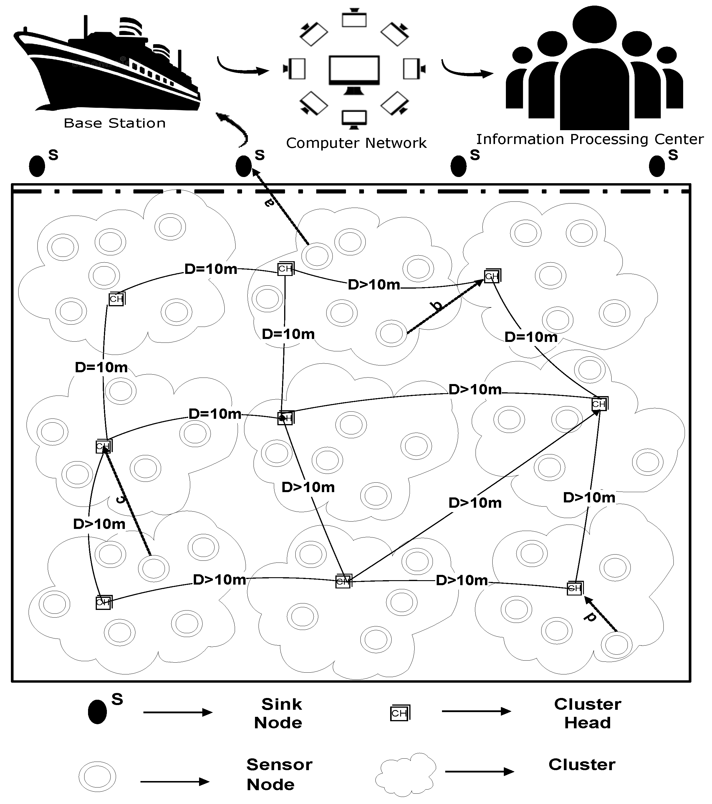
We have considered an underwater wireless network, where we dealt with three types of nodes. Normal nodes gather information regarding the surrounding region and transmit it to the CH node. CH will further send the aggregated packets to the sink node. Normal nodes can also forward the sensed data straight to the sink if they lie nearer to the sink node. In our proposed scheme, the sink is either positioned at the top of the water surface or specified otherwise.
One of the most famous techniques used for the sharing of location information is localization. In order to start network configuration, every node in WSN requires the area IDs, link status, relative coordinates, and received signal strengths of all other nodes in order to transmit data packets. However, this technique is itself a big technical challenge for researchers [
56]. U-(ACH)
is a localization based routing protocol, where all sensor nodes newscast a HELLO packet to the entire structure. In this study, we have used a range-free localization algorithm. In this technique, the mobile beacon node with an antenna is utilized to provide the data regarding distance and location for every other anonymous node. By doing so, all of the nodes get localized by their neighbors. However, the node with less remaining energy than the required energy cannot send a HELLO packet, since these nodes are not able to participate in further transmission. At the point when a node gets a HELLO packet from its neighbor, it examines the remaining energy and signal strength of the neighbor under certain conditions. If the neighbor meets the given conditions of residual energy and signal strength, then the neighbor turns into the next hop for transmitting the data to the next level. Depending upon the information provided in HELLO packets, every node attains complete information of all other sensor nodes and sink node(s).
In the proposed study, “switch to next node” is a function that is considered and called when a current node is dead or at the time of traversing for re-election, the node generates no response. The reason behind for calling switching function is that the node contains very less residual energy than the required energy and it cannot broadcast the HELLO packet. Furthermore, the effected node cannot participate anymore in the transmission of data packets and, hence, becomes isolated.
U-(ACH)
is a clustering based routing protocol, where CHs are selected on the basis of remaining energy. The remaining energy needs to be examined in order to select CHs. Therefore, the nodes having superlative remaining power are preferred [
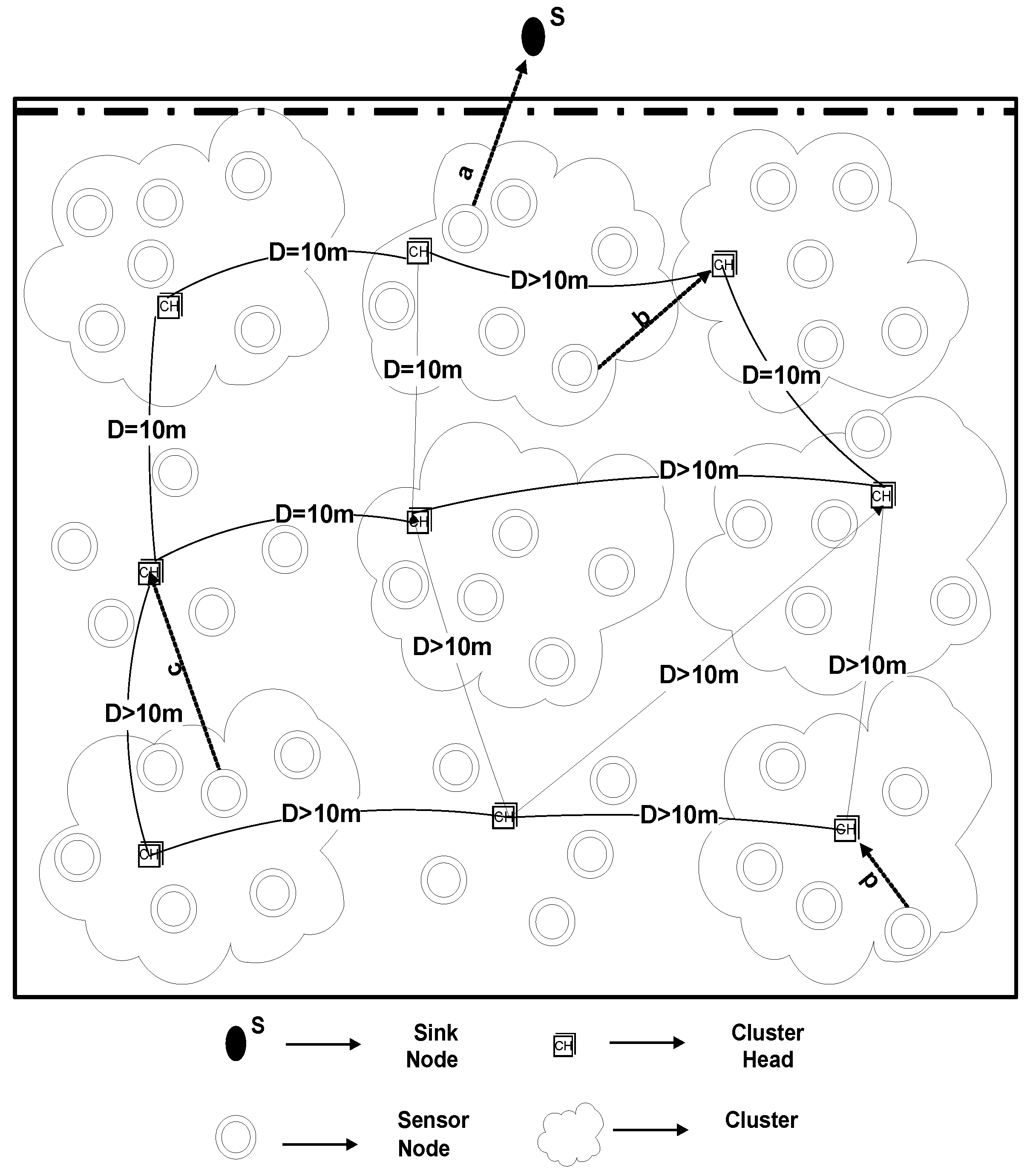
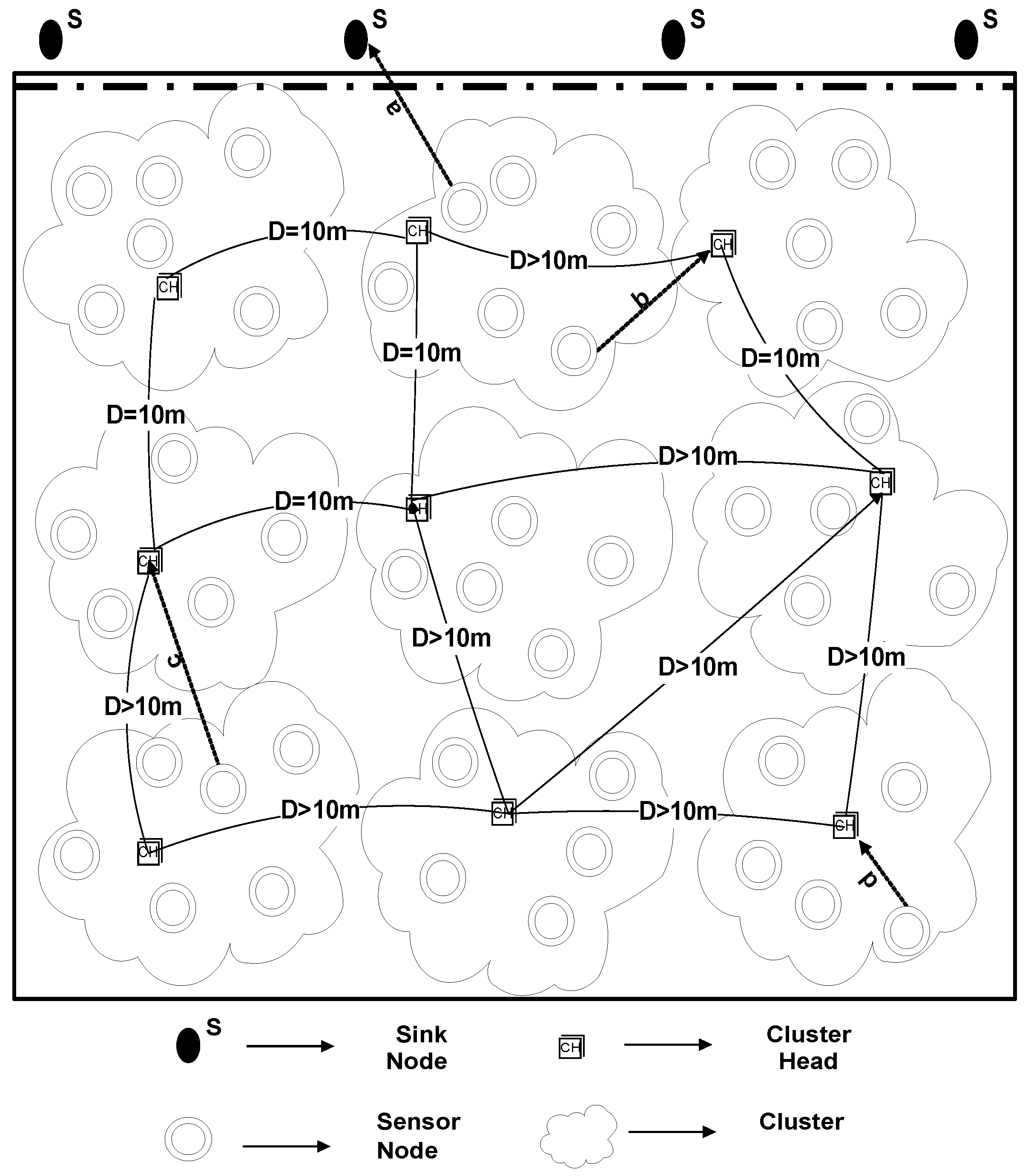
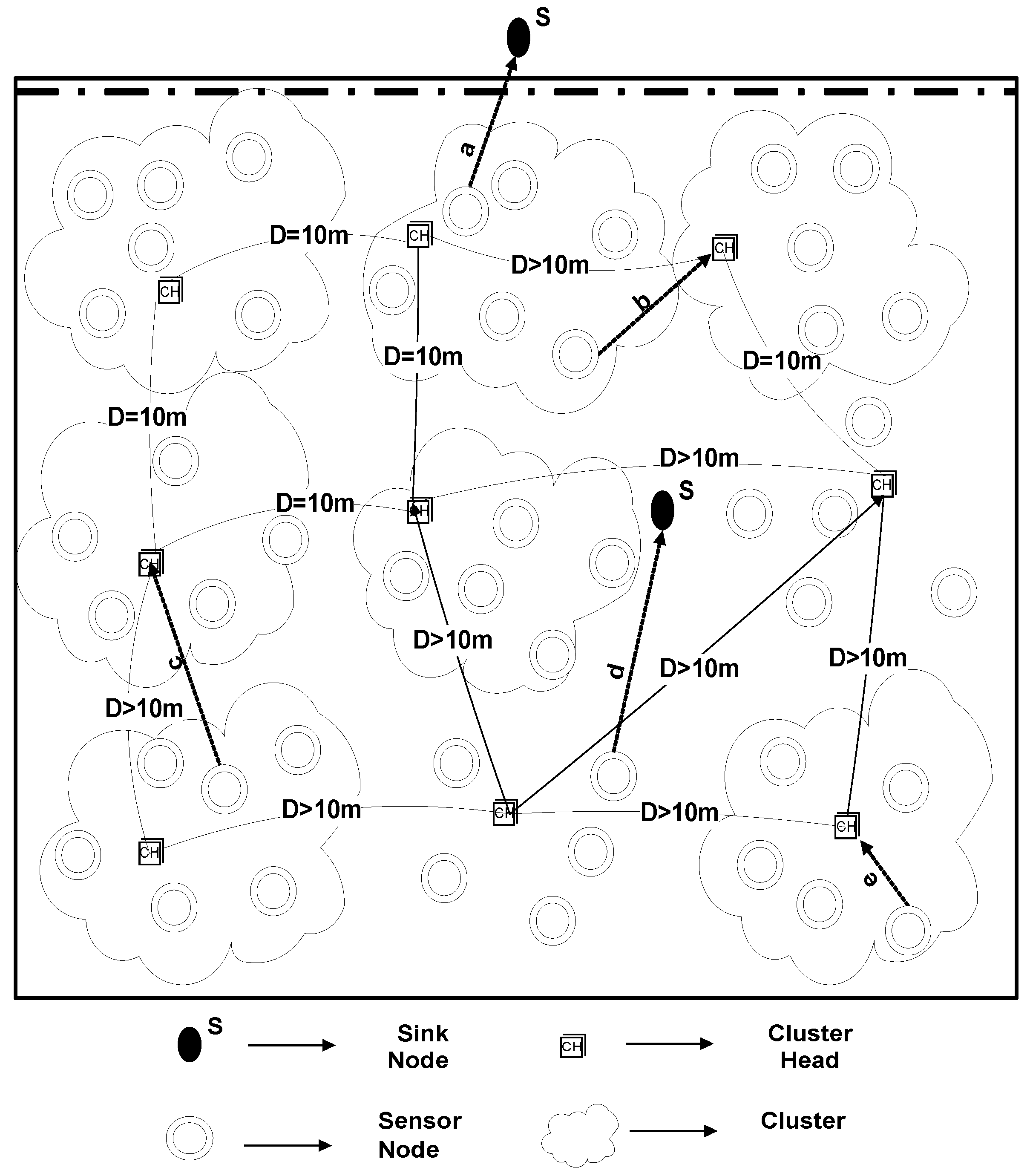
57]. For the sake of reducing the load on CHs, the optimum number of clusters is selected that results in balanced cluster size. For this, a selection criterion is defined that depends upon the 10 m distance of a selected CH from other elected CH, as demonstrated in
Figure 2. The reasoning behind the distance measure is to balance the load factor on each cluster. By doing so, many clusters would be equally loaded with the associated cluster members otherwise some clusters would have many associated cluster members while other clusters may be found under load. To avoid this controversy, the distance measure is considered in this study.
As per the results detailed in [
58], the ideal number of CHs for a network containing 100-nodes is proposed to be nearby 3–5. In any case, it ought to be noticed that the rate proposed by [
23] is determined dependent on the direct correspondence of CHs with the BS and, consequently, for the structures that utilize multi-hop transmission to move the collected data of CHs to the sink node or the schemes with various energy utilization, the forms may differ.
In the proposed study, in total 225 nodes were selected. According to [
59] and [
60], the range of distance is estimated in the range of 9 < Kopt < 11 when the base station is placed away from the field. Therefore, we have also considered, at most, 10 clusters at a time and, based on the Euclidean Distance measure, the CHs are selected. On average, 10m distance is considered for the selection of CHs to communicate in the desired network.
Each sensor node will sense the environment, collect the information of interest, and will forward its data packet to its nearest low depth CH. After this process, the selected CHs transmit the collective data straight towards the sink node(s). Contrarily, if the computed span in sensor node and sink is minimum than the CH, and node lies above the minimum distance CH, then the node will directly send data to sink.
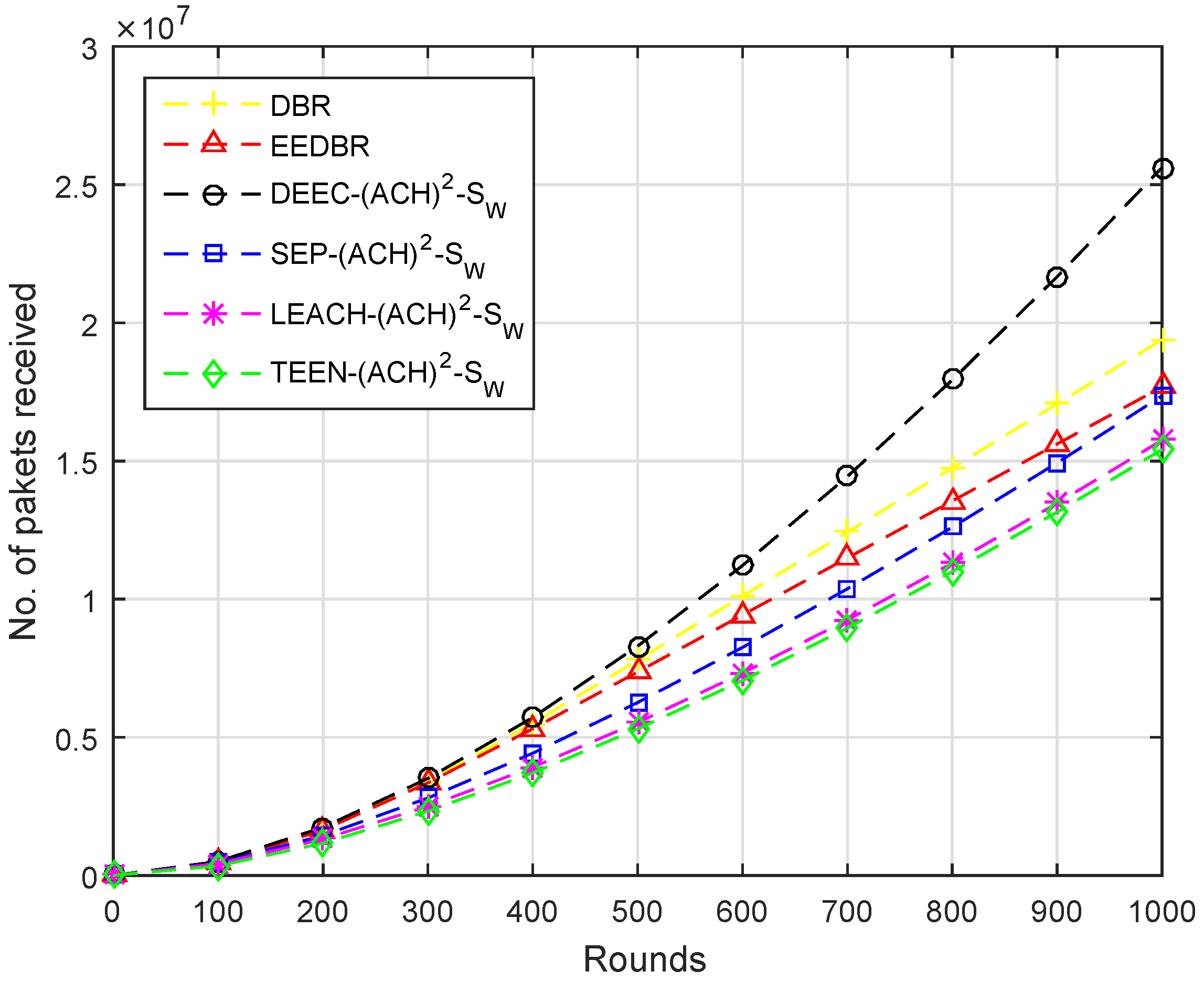
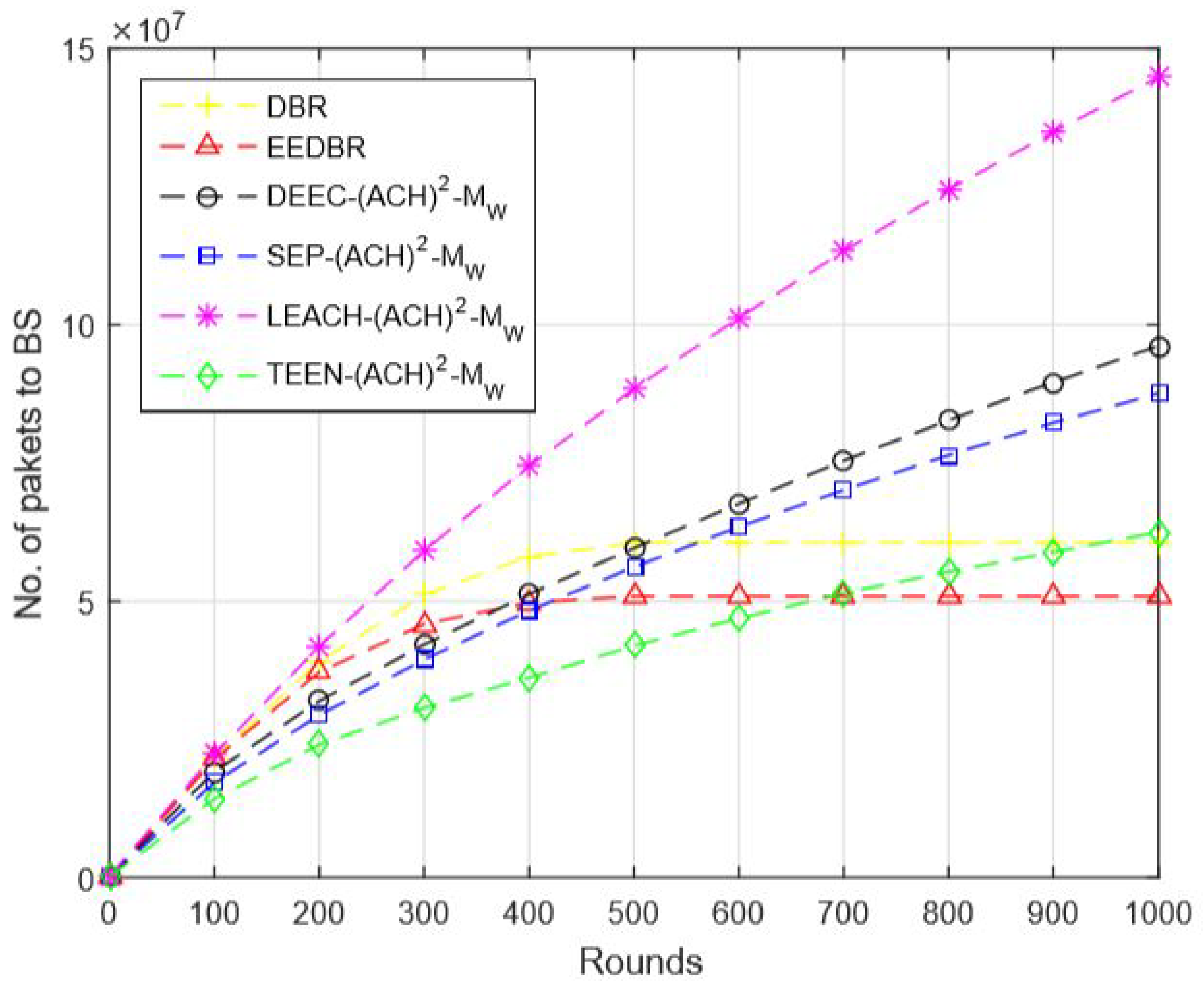
In order to conduct the simulation, for each scenario, we have considered 1000 rounds and for each round, we have assumed the number of nodes ‘N’ as 225. We have computed the number of nodes that were participating in sending the 10 kb data to BS in each round from the list of 225 nodes. Each carrier node transmits the 10 kb data packet to the BS. At the base station, the attainment of 10 kb data packet is equal to the one data packet. Likewise, we divide the received kb data to the 10 kb which shows the received data packets.
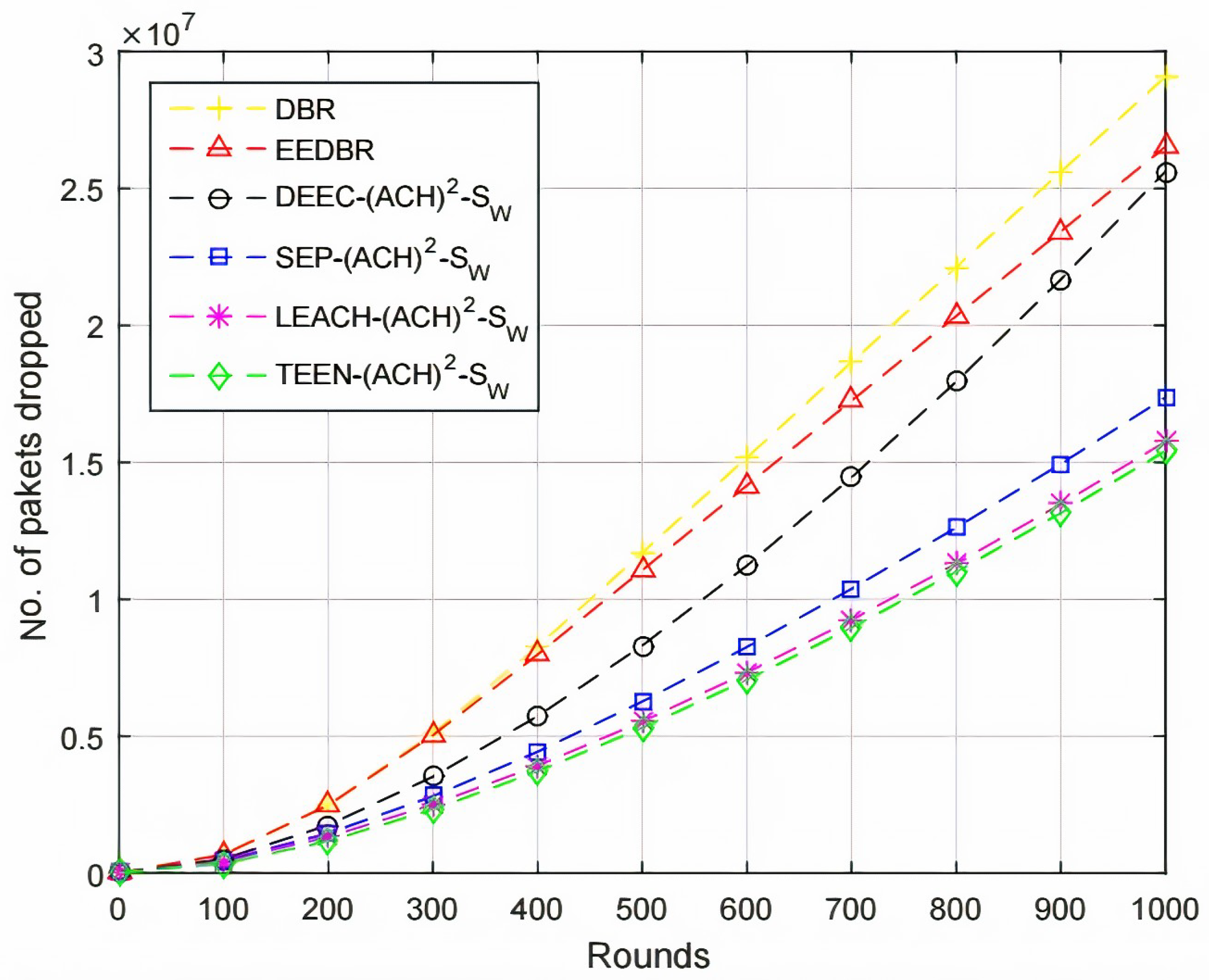
Secondly, the number of packets a node sends depends upon the residual energy a sensor node holds and a position where it is located. If a sensor node is located near to the CH or sink node then ultimately packet drop ratio will be less and more packets will be sent by a node to the BS. In an alternative case less number of packets, a node will transmit if its residual energy is less and it is located far away from the CH or sink node.
WSNs are divided into two classes while considering energy, homogeneous, and heterogeneous [
52]. We have considered four routing protocols in which two of them are homogenous, such as (LEACH, TEEN) and the rest of the two are heterogenous, which are (SEP, DEEC). The working principle of LEACH-(ACH)
, TEEN-(ACH)
, SEP-(ACH)
, CH election, selection, and DEEC-(ACH)
is demonstrated in Algorithms 1–5, respectively.
| Algorithm 1 LEACH-ACH. |
 |
LEACH-ACH, as shown in Algorithm 1, is the simplest algorithm where no hard/soft threshold and advance energy is required. Initially the number of nodes and rounds are specified for simulation. Next, the energy of node is computed to identify whether it is alive or dead. After wards, total energy of the node is computed. The count is incremented from node 1 to node 2 and so on until no dead node is found.
Afterwards, the E_avg and K_opt values are computed. A call is generated to the CH-Election function and then CH-selection function. The distance from sensor node to CH and sink node is computed. Sensor node will transmit data to the CH if its distance value is less when compared to sink node or vice versa.
TEEN-ACH, as shown in Algorithm 2, is a two-level clustering scheme, where the CH broadcasts two thresholds to its associated members. The first is a hard threshold while the other is known as a soft threshold, which demonstrated the variation in the value of a sensed feature. The hard threshold is responsible for sending data only when the sensed feature range is satisfied.
Initially, the number of nodes and rounds is specified for simulation. During the transformation of data packets, a condition is required to be satisfied in which hard and soft thresholds are defined. Afterwards, the energy of the node is computed to identify whether it is alive or dead. The next step is the computation of total energy of the node. The count is incremented from node 1 to node 2, and so on, until no dead node is found.
| Algorithm 2 TEEN-ACH. |
 |
Next, the E_avg and K_opt values are computed. A call is generated to the CH-Election function and then CH-selection function. The distance from the sensor node to CH and sink node is computed. The sensor node will transmit data to the CH if its distance value is less when compared to the sink node or vice versa. The sensor node forwards for the first time when the sensed value is total up to the hard threshold value. However, in a case to transmit for the second time, the sensed value should be larger than the hard threshold and it should be either larger or equal to the soft threshold value as shown in the algorithm.
| Algorithm 3 SEP-ACH. |
 |
Like DEEC-ACH, the SEP-ACH scheme is also based on heterogeneous scheme comprising of two different levels of energies, as shown in Algorithm 3. Initially, the number of nodes and rounds is specified for simulation, m is the percentage of advance nodes. denotes the normal node, while denotes the advance nodes. Here, time more energy is assigned to the advance nodes.
The probability of normal and advance nodes are computed. After the computation of probabilities, the energy of the node is computed to identify whether it is alive or dead. Afterwards, the total energy of the node is computed. The count is incremented from node 1 to node 2 and so on until no dead node is found. Afterwards, the E_avg and K_opt values are computed. Like other schemes here, CH-election and selection will not be called, because, in SEP-ACH
, only CH is responsible for transmitting the data. If the sensor node lies near to the sink node, still normal node is not allowed to send data directly to the sink node. Due to this nature of SEP-ACH
scheme, the network’s lifetime is sharply decreased at a very high speed.
| Algorithm 4 CH election, selection. |
 |
For CH-election, initially cluster variable is assigned 0 value and the number of nodes is considered in a way, as already considered. For a node to become CH, its residual energy needs to be more than the average residual energy of the network, if the condition satisfies, then the sensor node is elected to be a CH. The CHs are elected until the K_opt value is reached, as shown in Algorithm 4.
For selection, the distance from all of the elected nodes towards every next node is computed, if the distance is greater than the specified value i.e., 10m then the elected node is selected as CH or in alternative case elected node again becomes a normal sensor node. For each round, election and selection process executes.
| Algorithm 5 DEEC-ACH. |
 |
DEEC-ACH is a Heterogeneous WSN that comprises of two or various sorts of sensor nodes having different energy levels as shown in Algorithm 5. Initially, the number of nodes and rounds is specified for simulation. Next, the energy of the node is computed to identify whether it is alive or dead. Afterwards, the total energy of a node is computed. The count is incremented from node 1 to node 2 and so on until no dead node is found.
The DEEC-ACH
convention depends on a two-level heterogeneous WSN in which the sensor nodes are equipped with normal E0 and advance Ea energy levels. The normal energy of the network is given as
After computing E_avg, we need to compute K_opt in order to create the number of desired clusters. Toward the start of each round, the choice with regards to whether the nodes are CH is chosen by the limit bound. The limit bound is suggested, as below. It is imperative to take note of that ideal likelihood (P(i)) is somewhere in the range of 0 and 1, which is the part staying in the opposite of the P(i) with r. This is the reason mod is utilized. This leftover is deducted by 1 and Temp is determined.
if S.E > E_avg then
otherwise zero.
Next, CH-selection code is called to compute the distance. For a node, to select CH, if the distance from the sink node is less when compared to the distance from the cluster, then a node will directly send its data packet to the sink node. This is how DEEC-ACH works.
In subject to the system’s performance, the list of metrics for evaluation purposes are considered, which are as follows:
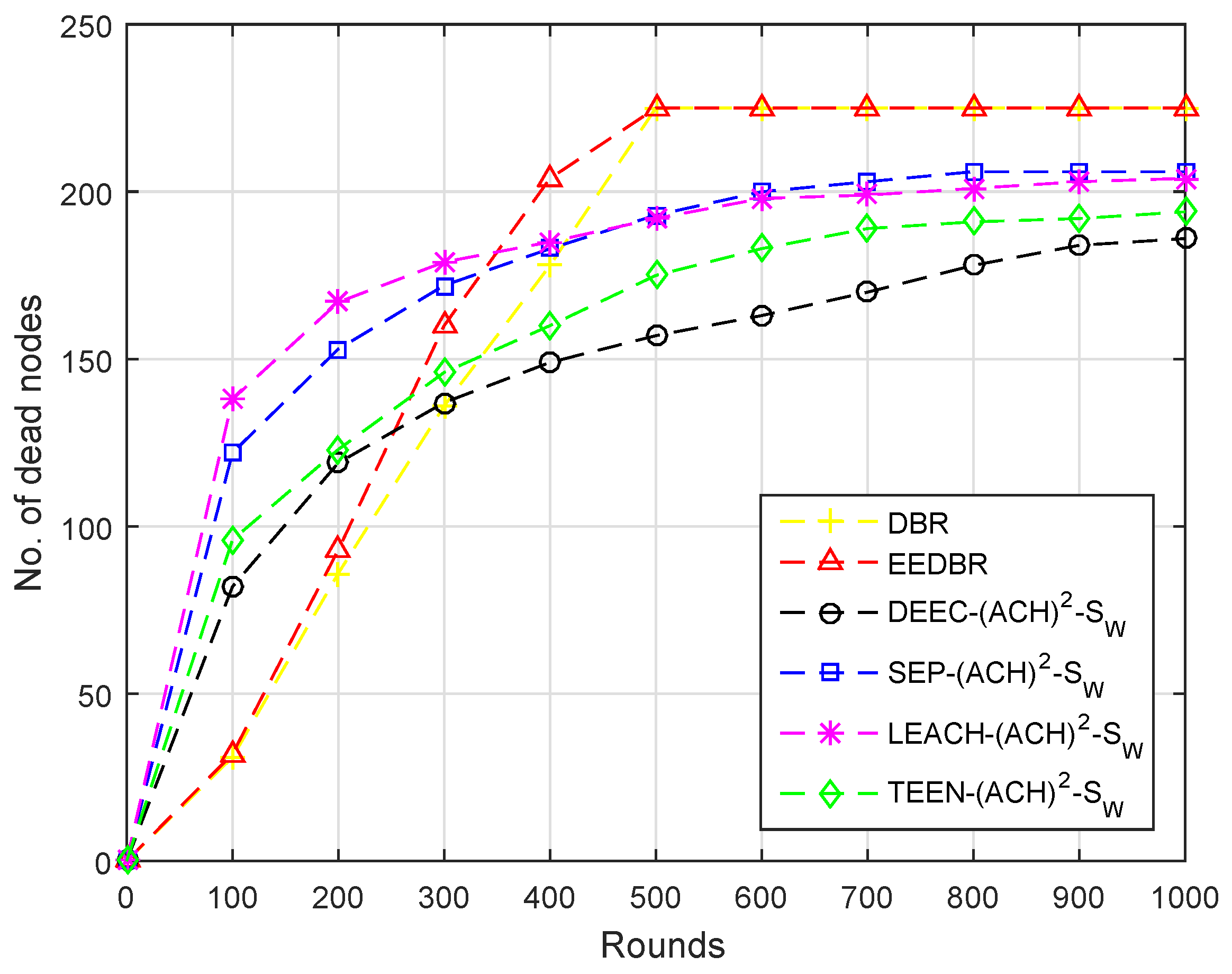
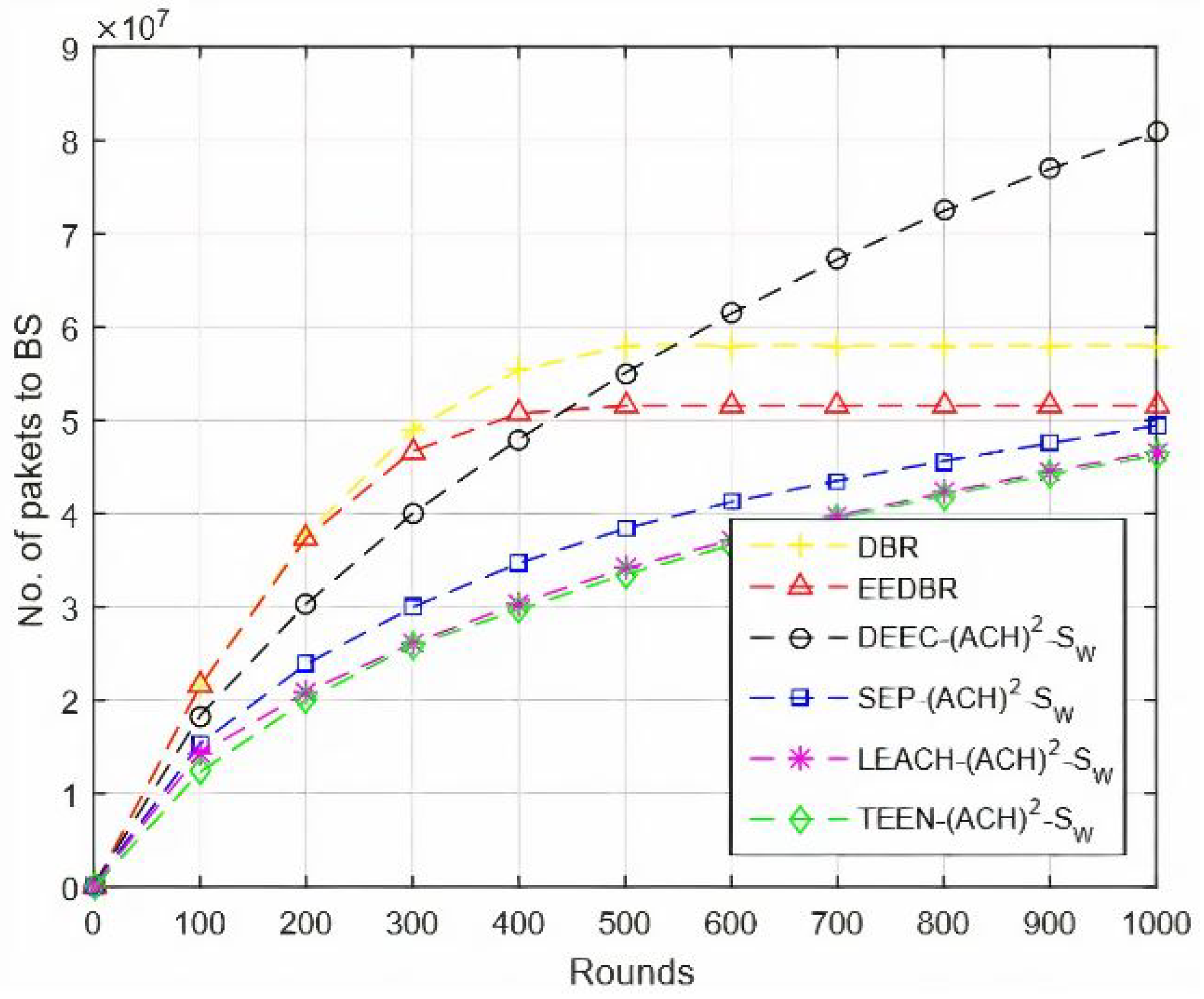
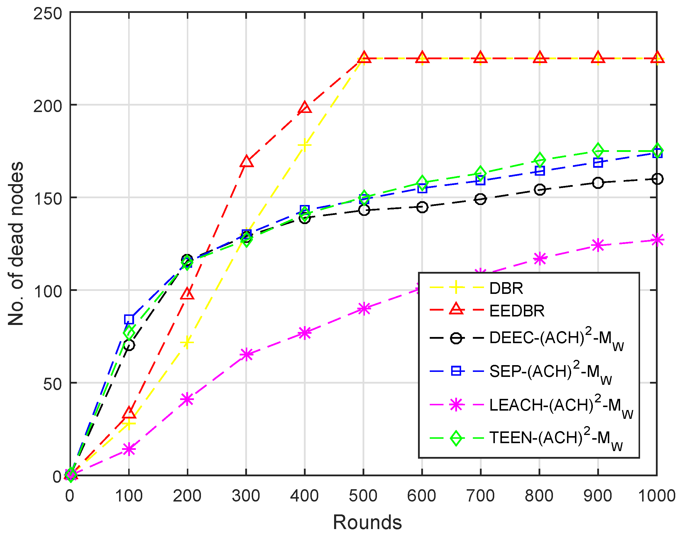
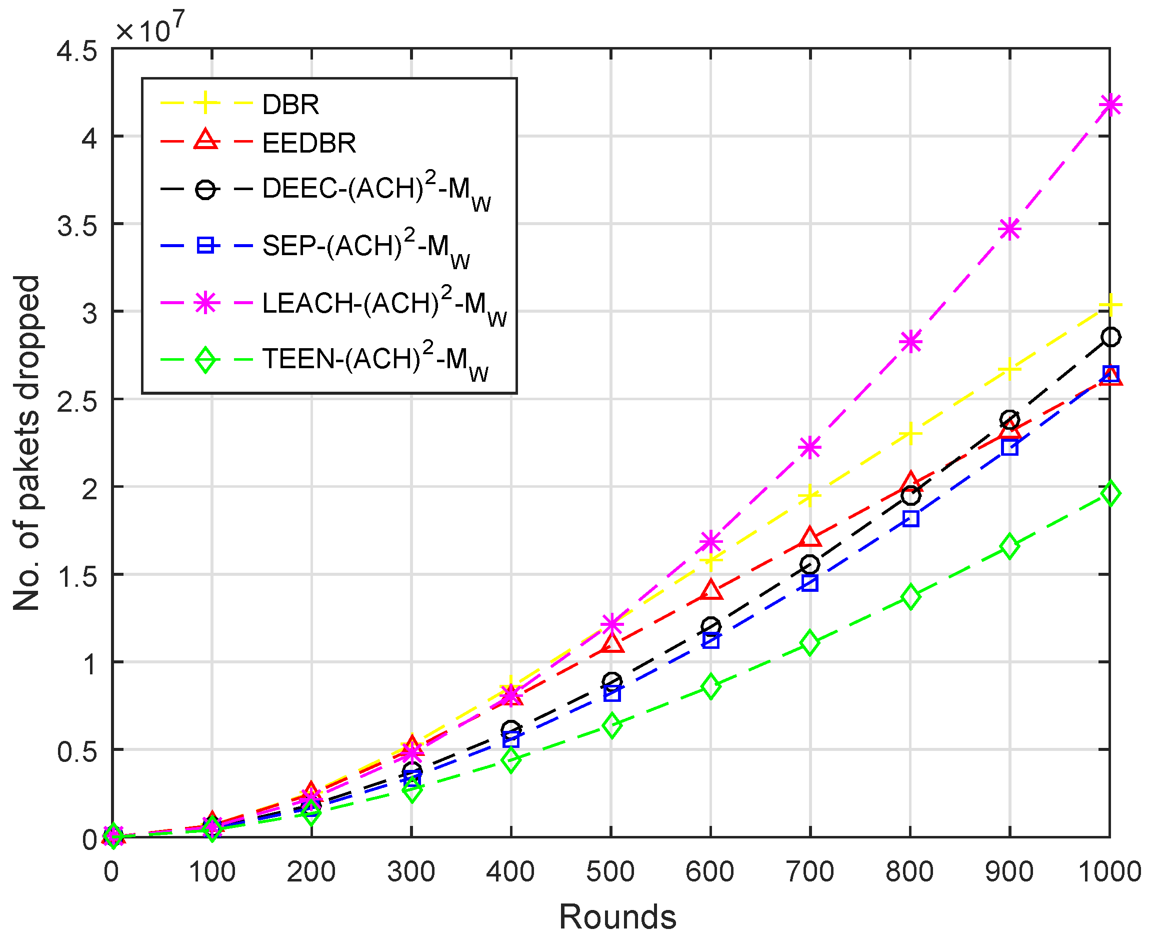
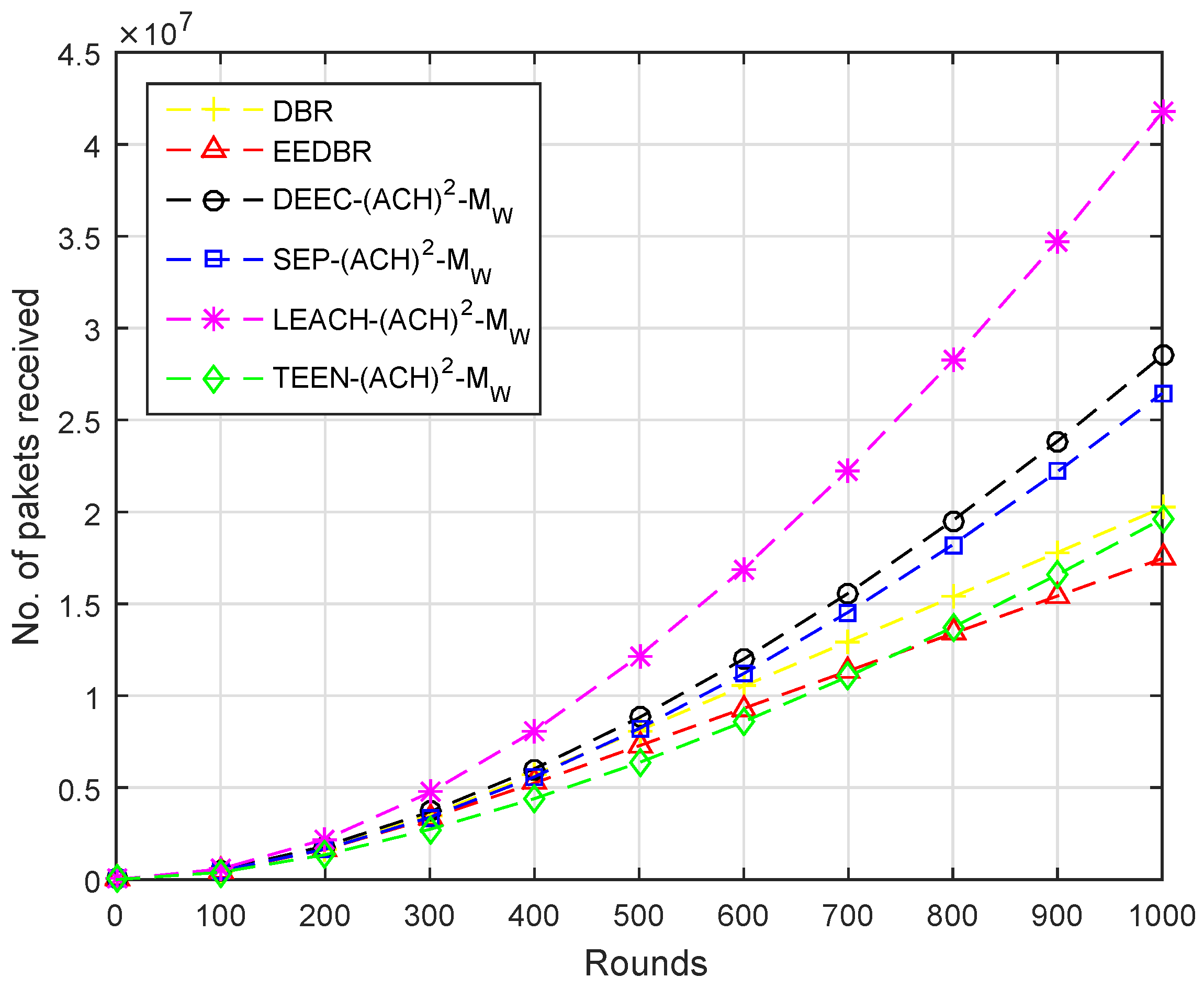
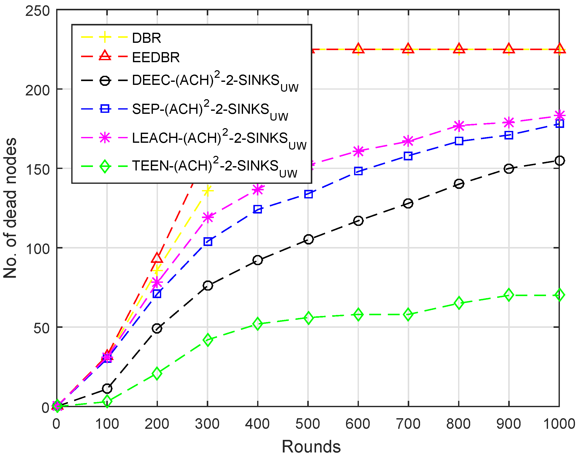
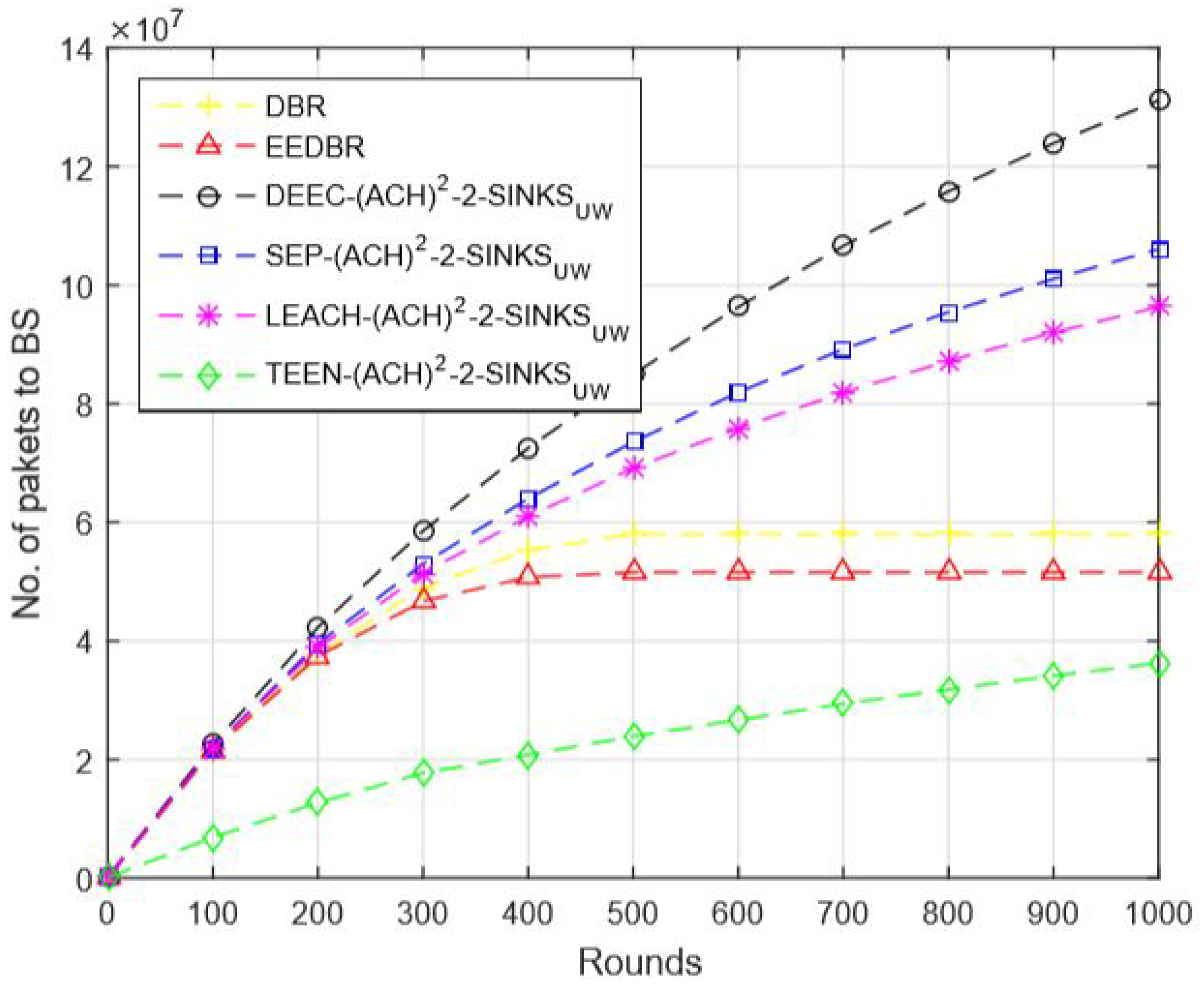
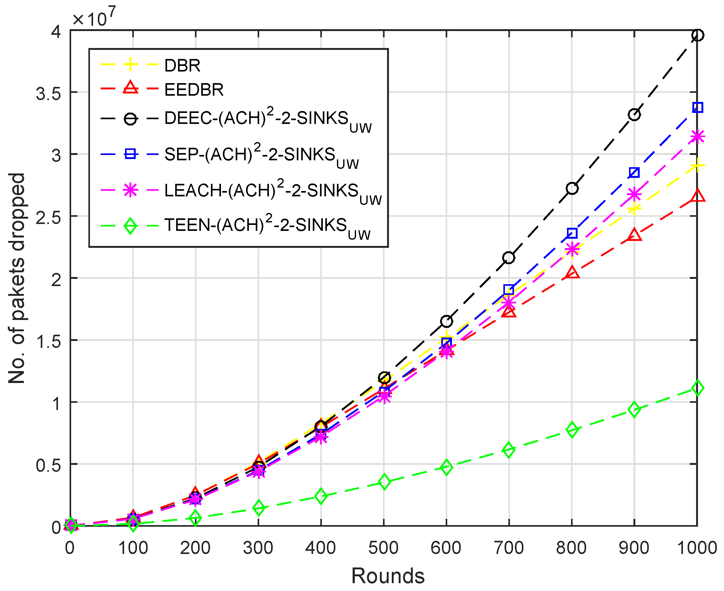
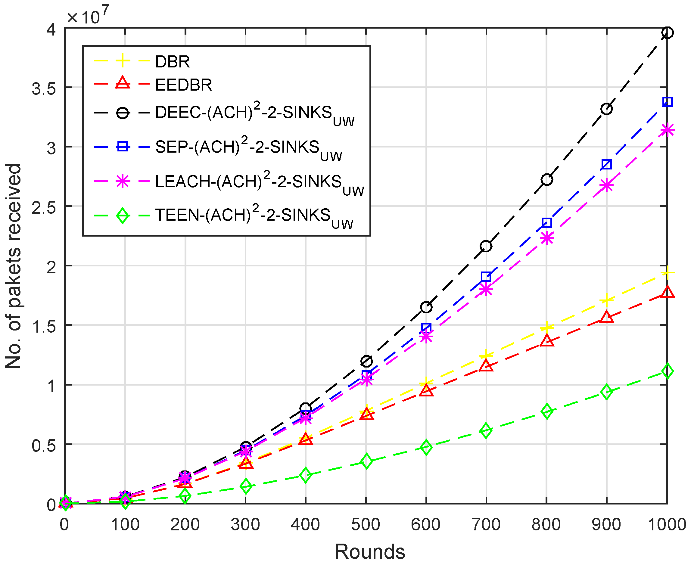
The first metric is the Stability period, which is the timestamp since the creation of network till all the nodes alive. Next is the Un-stability period which is the timestamp from the end of stability period till the end of the network. Afterwards, the number of packets send to BS is the metric that shows the total number of packets from the start of the network that are straightly sent to the base station. The number of packets dropped occurs due to attenuation noise and link status packets dropped. The next metric is Throughput, which demonstrates the number of data packets successfully collected at the Base Station per round. The last metric that we considered to evaluate the scheme is the computation of the number of Dead nodes having zero energy.
To gain the ideal results, three different ways for both homogeneous and heterogeneous routing protocols are projected and discussed, which are as follows: positioning single sink at water surface; positioning multiple sinks at water surface; and locating sinks at both positions, water surface and underwater.


 ,
, 


