Advanced Monitoring Systems Based on Battery-Less Asset Tracking Modules Energized through RF Wireless Power Transfer


Abstract
1. Introduction
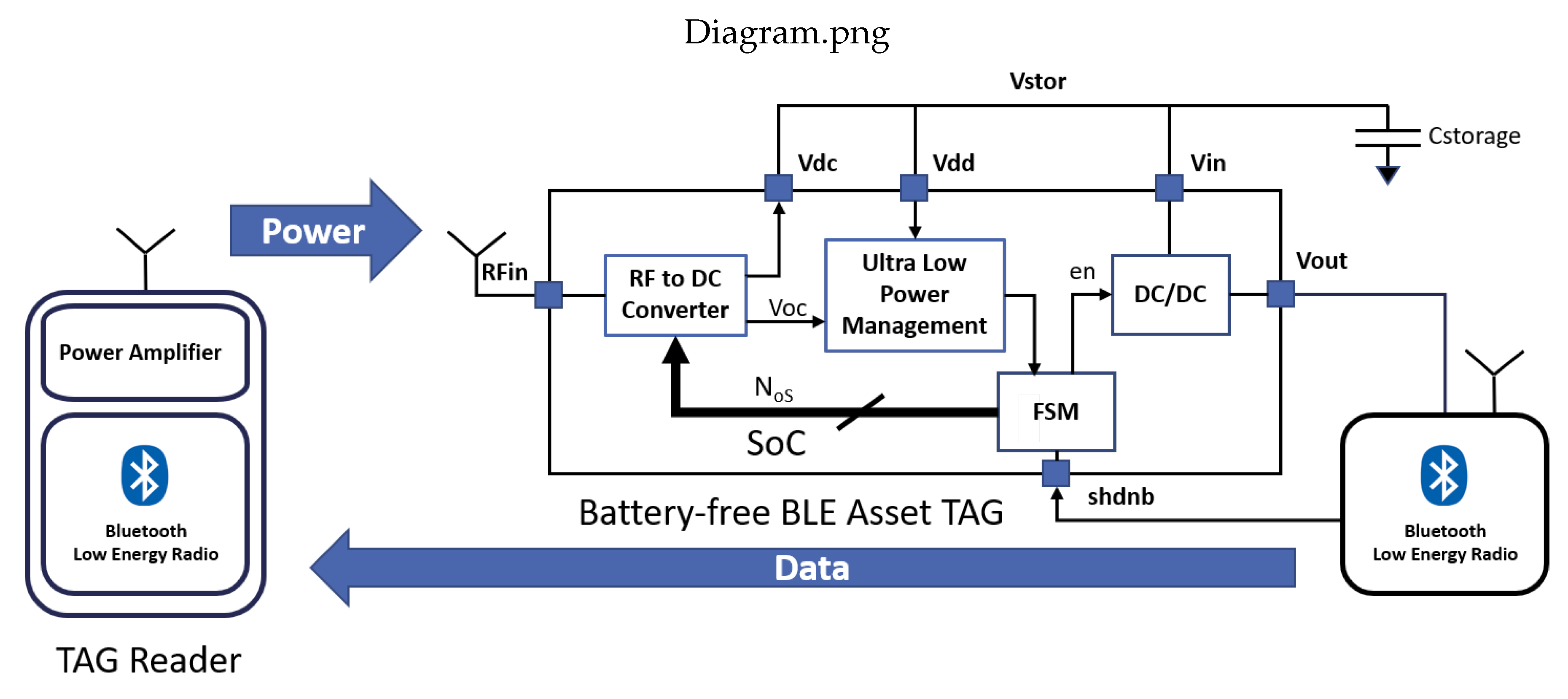
2. System Description
3. System Design
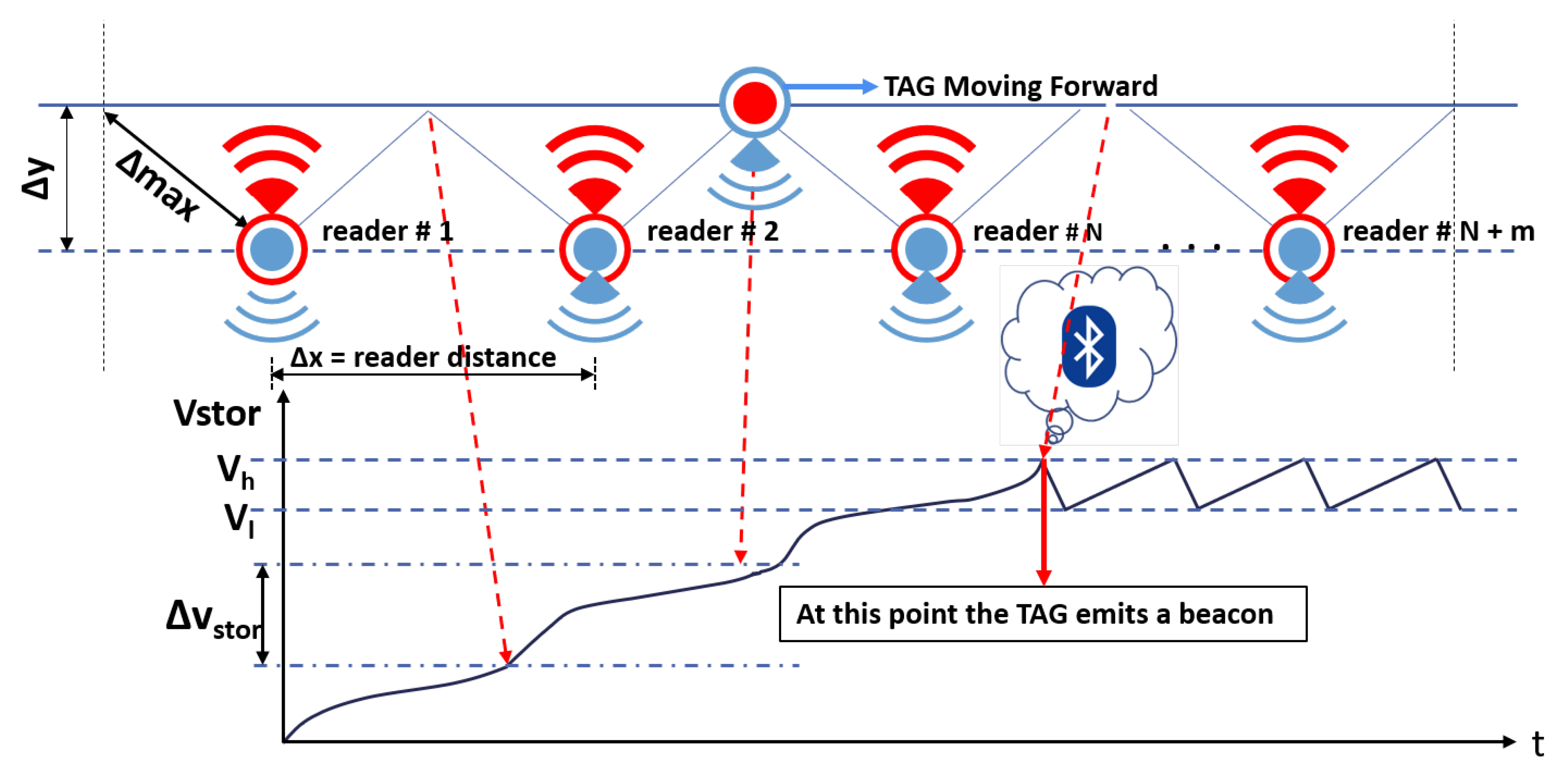
4. Speed Detection
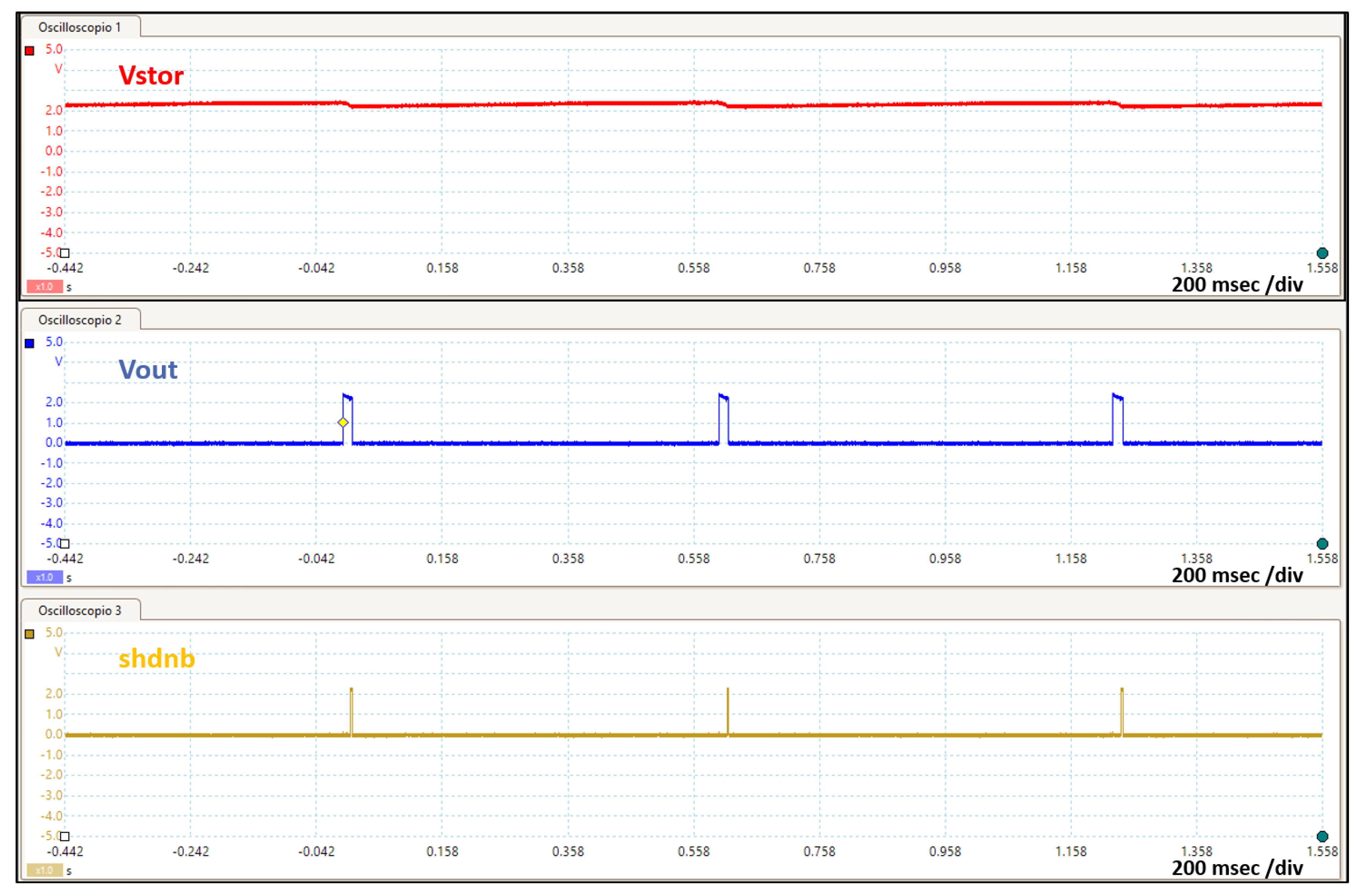
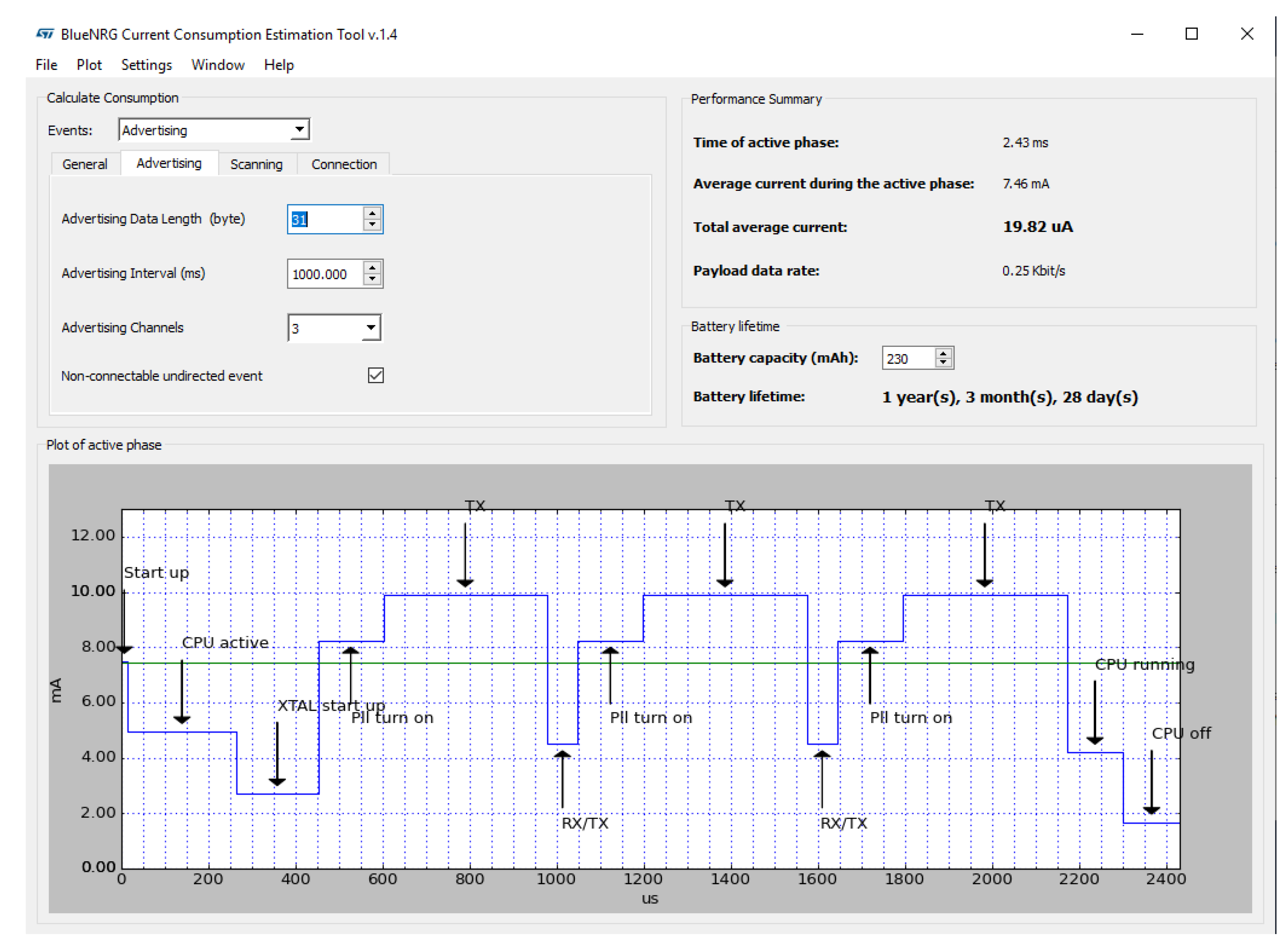
5. Experimental Results
6. Conclusions
Author Contributions
Funding
Acknowledgments
Conflicts of Interest
References
- Manyika, J.; Chui, M.; Bisson, P.; Woetzel, J.; Dobbs, R.; Bughin, J.; Aharon, D. Unlocking the Potential of the Internet of Things; McKinsey Global Institute: New York, NY, USA, 2015. [Google Scholar]
- Alioto, M. Enabling the Internet of Things: From Integrated Circuits to Integrated Systems; Springer: Berlin/Heidelberg, Germany, 2017. [Google Scholar]
- Abella, C.; Bonina, S.; Cucuccio, A.; D’Angelo, S.; Giustolisi, G.; Grasso, A.; Imbruglia, A.; Mauro, G.; Nastasi, G.; Palumbo, G.; et al. Autonomous Energy-Efficient Wireless Sensor Network Platform for Home/Office Automation. IEEE Sensors J. 2019, 9, 3501–3512. [Google Scholar] [CrossRef]
- Viani, F.; Robol, F.; Polo, A.; Rocca, P.; Oliveri, G.; Massa, A. Wireless architectures for heterogeneous sensing in smart home applications: Concepts and real implementation. Proc. IEEE 2013, 101, 2381–2396. [Google Scholar] [CrossRef]
- Alioto, M.; Shahghasemi, M. The Internet of Things on its edge: Trends toward its tipping point. IEEE Consum. Electron. Mag. 2018, 7, 77–87. [Google Scholar] [CrossRef]
- Teixidó, P.; Gómez-Galán, J.; Gómez-Bravo, F.; Sánchez-Rodríguez, T.; Alcina, J.; Aponte, J. Low-Power Low-Cost Wireless Flood Sensor for Smart Home Systems. Sensors 2018, 18, 3817. [Google Scholar] [CrossRef]
- Guo, K.; Lu, Y.; Gao, H.; Cao, R. Artificial intelligence-based semantic internet of things in a user-centric smart city. Sensors 2018, 18, 1341. [Google Scholar] [CrossRef]
- Mujica, G.; Rodriguez-Zurrunero, R.; Wilby, M.; Portilla, J.; Rodríguez González, A.; Araujo, A.; Riesgo, T.; Vinagre Díaz, J. Edge and Fog Computing Platform for Data Fusion of Complex Heterogeneous Sensors. Sensors 2018, 18, 3630. [Google Scholar] [CrossRef]
- Andò, B.; Baglio, S.; La Malfa, S.; Pistorio, A.; Trigona, C. A smart wireless sensor network for AAL. In Proceedings of the 2011 IEEE International Workshop on Measurements and Networking Proceedings (M&N), Anacapri, Italy, 10–11 October 2011; pp. 122–125. [Google Scholar]
- La Rosa, R.; Dehollain, C.; Pellitteri, F.; Miceli, R.; Livreri, P. An RF Wireless Power Transfer system to power battery-free devices for asset tracking. In Proceedings of the 26th IEEE International Conference on Electronics Circuits and Systems (ICECS), Genoa, Italy, 27–29 November 2019; pp. 1–4. [Google Scholar]
- Zhu, M.; Hassanalieragh, M.; Chen, Z.; Fahad, A.; Shen, K.; Soyata, T. Energy-Aware Sensing in Data-Intensive Field Systems Using Supercapacitor Energy Buffer. IEEE Sensors J. 2018, 16, 3372–3383. [Google Scholar] [CrossRef]
- Mouapi, A.; Hakem, N.; Delisle, G.Y. A new approach to design of RF energy harvesting system to enslave wireless sensor networks. ICT Express 2017, 4, 228–233. [Google Scholar] [CrossRef]
- Shaikh, F.K.; Zeadally, S. Energy harvesting in wireless sensor networks: A comprehensive review. Renew. Sustain. Energy Rev. 2016, 55, 1041–1054. [Google Scholar] [CrossRef]
- Wu, F.; Rüdiger, C.; Yuce, M.R. Real-time performance of a self-powered environmental IoT sensor network system. Sensors 2017, 17, 282. [Google Scholar] [CrossRef]
- Cheung, W.F.; Lin, T.H.; Lin, Y.C. A real-time construction safety monitoring system for hazardous gas integrating wireless sensor network and building information modeling technologies. Sensors 2018, 18, 436. [Google Scholar] [CrossRef] [PubMed]
- Habibzadeh, H.; Qin, Z.; Soyata, T.; Kantarci, B. Large-scale distributed dedicated-and non-dedicated smart city sensing systems. IEEE Sensors J. 2017, 17, 7649–7658. [Google Scholar] [CrossRef]
- Martinez, B.; Monton, M.; Vilajosana, I.; Prades, J.D. The power of models: Modeling power consumption for IoT devices. IEEE Sensors J. 2015, 15, 5777–5789. [Google Scholar] [CrossRef]
- Qin, H.; Zhang, W. Zigbee-assisted power saving management for mobile devices. IEEE Trans. Mob. Comput. 2014, 13, 2933–2947. [Google Scholar] [CrossRef]
- Chen, J.H.; Chen, Y.S.; Jiang, Y.L. Energy-Efficient Scheduling for Multiple Latency-Sensitive Bluetooth Low Energy Nodes. IEEE Sensors J. 2018, 18, 849–859. [Google Scholar] [CrossRef]
- Aziz, A.A.; Sekercioglu, Y.A.; Fitzpatrick, P.; Ivanovich, M. A survey on distributed topology control techniques for extending the lifetime of battery powered wireless sensor networks. IEEE Commun. Surv. Tutorials 2013, 15, 121–144. [Google Scholar] [CrossRef]
- Beutel, J.; Kasten, O.; Mattern, F.; Römer, K.; Siegemund, F.; Thiele, L. Prototyping wireless sensor network applications with BTnodes. In European Workshop on Wireless Sensor Networks; Springer: Berlin/Heidelberg, Germany, 2004; pp. 323–338. [Google Scholar]
- Nachman, L.; Kling, R.; Adler, R.; Huang, J.; Hummel, V. The Intel® Mote platform: A Bluetooth-based sensor network for industrial monitoring. In Proceedings of the 4th International Symposium on Information Processing in Sensor Networks; IEEE Press: Los Angeles, CA, USA, 2005; p. 61. [Google Scholar]
- Livreri, P.; Castiglia, V.; Pellitteri, F.; Miceli, R. Design of a Battery/Ultracapacitor Energy Storage System for Electric Vehicle Applications. In Proceedings of the 2018 IEEE 4th International Forum on Research and Technology for Society and Industry (RTSI), Palermo, Italy, 10–13 September 2018; pp. 1–5. [Google Scholar]
- Pellitteri, F.; Castiglia, V.; Livreri, P.; Miceli, R. Analysis and design of bi-directional DC-DC converters for ultracapacitors management in EVs. In Proceedings of the 2018 Thirteenth International Conference on Ecological Vehicles and Renewable Energies (EVER), Monte-Carlo, Monaco, 10–12 April 2018; pp. 1–6. [Google Scholar]
- Yamawaki, A.; Serikawa, S. Battery Life Estimation of Sensor Node with Zero Standby Power Consumption. In Proceedings of the 2016 IEEE Intl Conference on Computational Science and Engineering (CSE) and IEEE Intl Conference on Embedded and Ubiquitous Computing (EUC) and 15th Intl Symposium on Distributed Computing and Applications for Business Engineering (DCABES), Paris, France, 24–26 August 2016; pp. 166–172. [Google Scholar]
- La Rosa, R.; Trigona, C.; Andò, B.; Baglio, S. MEMS based Transducer for Zero-Energy Standby Application. In Proceedings of the 2019 II Workshop on Metrology for Industry 4.0 and IoT (MetroInd4. 0&IoT), Naples, Italy, 4–6 June 2019; pp. 12–15. [Google Scholar]
- Perilli, L.; Scarselli, E.F.; La Rosa, R.; Canegallo, R. Wake-Up Radio Impact in Self-Sustainability of Sensor and Actuator Wireless Nodes in Smart Home Applications. In Proceedings of the 2018 Ninth International Green and Sustainable Computing Conference (IGSC), Pittsburgh, PA, USA, 22–24 October 2018; pp. 1–7. [Google Scholar]
- La Rosa, R.; Aiello, N.; Zoppi, G. An innovative system capable to turn on any turned off electrical appliance by means of an efficient optical energy transfer. In Proceedings of the PCIM Europe 2014, International Exhibition and Conference for Power Electronics, Intelligent Motion, Renewable Energy and Energy Management, Nuremberg, Germany, 20–22 May 2014; VDE:VERLAG GMBH: Berlin, Germany; Offenbach, Germany, 2014; pp. 1559–1566. [Google Scholar]
- La Rosa, R.; Aiello, N.; Zoppi, G. RF remotely-powered integrated system to nullify standby power consumption in electrical appliances. In Proceedings of the 42nd Annual Conference of the IEEE Industrial Electronics Society (IECON 2016), Florence, Italy, 23–26 October 2016; pp. 1162–1164. [Google Scholar]
- Trigona, C.; Andò, B.; Baglio, S.; La Rosa, R.; Zoppi, G. Vibration-based Transducer for Zero-Energy standby applications. In Proceedings of the Sensors Applications Symposium (SAS), Catania, Italy, 20–22 April 2016; pp. 1–4. [Google Scholar]
- Trigona, C.; Andò, B.; Baglio, S.; La Rosa, R.; Zoppi, G. Sensors for Kinetic Energy Measurement Operating on “Zero-Current Standby”. IEEE Trans. Instrum. Meas. 2017, 66, 812–820. [Google Scholar] [CrossRef]
- Gerber, D.; Meier, A.; Hosbach, R.; Liou, R. Zero Standby Solutions with Optical Energy Harvesting from a Laser Pointer. Electronics 2018, 7, 292. [Google Scholar] [CrossRef]
- Bedogni, L.; Bononi, L.; Canegallo, R.; Carbone, F.; Di Felice, M.; Scarselli, E.F.; Montori, F.; Perilli, L.; Cinotti, T.S.; Trotta, A. Dual-Mode Wake-Up Nodes for IoT Monitoring Applications: Measurements and Algorithms. In Proceedings of the 2018 IEEE International Conference on Communications (ICC), Kansas City, MO, USA, 20–24 May 2018; pp. 1–7. [Google Scholar]
- Trotta, A.; Di Felice, M.; Bononi, L.; Natalizio, E.; Perilli, L.; Scarselli, E.F.; Cinotti, T.S.; Canegallo, R. BEE-DRONES: Energy-efficient Data Collection on Wake-Up Radio-based Wireless Sensor Networks. In Proceedings of the IEEE INFOCOM 2019-IEEE Conference on Computer Communications Workshops (INFOCOM WKSHPS), Paris, France, 29 April–2 May 2019; pp. 547–553. [Google Scholar]
- Rosa, R.L.; Zoppi, G.; Finocchiaro, A.; Papotto, G.; Donato, L.D.; Sorbello, G.; Bellomo, F.; Carlo, C.A.D.; Livreri, P. An over-the-distance wireless battery charger based on RF energy harvesting. In Proceedings of the 2017 14th International Conference on Synthesis, Modeling, Analysis and Simulation Methods and Applications to Circuit Design (SMACD), Giardini Naxos, Italy, 12–15 June 2017; pp. 1–4. [Google Scholar]
- de Fazio, R.; Cafagna, D.; Marcuccio, G.; Visconti, P. Limitations and Characterization of Energy Storage Devices for Harvesting Applications. Energies 2020, 13, 783. [Google Scholar] [CrossRef]
- Selvan, S.; Zaman, M.; Gobbi, R.; Wong, H.Y. Recent advances in the design and development of radio frequency-based energy harvester for powering wireless sensors: A review. J. Electromagn. Waves Appl. 2018, 32, 2110–2134. [Google Scholar] [CrossRef]
- Pandey, S.; Zalke, J.; Nandanwar, R.; Verma, A. Design and Analysis of Piezoelectric Energy Harvesting Circuit for Rechargeable Ultra-Low Weight Lithium-Ion Batteries. J. Eng. Sci. Technol. Rev. 2018, 11, 77–83. [Google Scholar] [CrossRef]
- Altinel, D.; Kurt, G.K. Modeling of Multiple Energy Sources for Hybrid Energy Harvesting IoT Systems. IEEE Internet Things J. 2019, 6, 10846–10854. [Google Scholar] [CrossRef]
- Anwar, A.; Shah, S.T.; Hasan, S.F.; Shin, D.R. SWIPT-Based Three-Step Multiplicative Amplify-and-Forward Two-Way Relay Networks with Non-Linear Energy Conversion Model. In Proceedings of the 2018 IEEE 4th International Conference on Computer and Communications (ICCC), Chengdu, China, 7–10 December 2018; pp. 152–157. [Google Scholar]
- La Rosa, R.; Dehollain, C.; Pillitteri, F.; Miceli, R.; Livreri, P. A Battery-free Asset Monitoring System based on RF Wireless Power Transfer. In Proceedings of the 2020 IEEE 20th Melecon Conference, Palermo, Italy, 16–18 June 2020; pp. 1–4. [Google Scholar]
- La Rosa, R.; Zoppi, G.; Di Donato, L.; Sorbello, G.; Di Carlo, C.; Livreri, P. A Battery-Free Smart Sensor Powered with RF Energy. In Proceedings of the 2018 IEEE 4th International Forum on Research and Technology for Society and Industry (RTSI), Palermo, Italy, 10–13 September 2018; pp. 1–4. [Google Scholar]
- La Rosa, R.; Trigona, C.; Zoppi, G.; Di Carlo, C.; Di Donato, L.; Sorbello, G. RF energy scavenger for battery-free Wireless Sensor Nodes. In Proceedings of the 2018 IEEE International Instrumentation and Measurement Technology Conference (I2MTC), Houston, TX, USA, 14–17 May 2018; pp. 1–5. [Google Scholar]
- Castorina, G.; Di Donato, L.; Morabito, A.F.; Isernia, T.; Sorbello, G. Analysis and design of a concrete embedded antenna for wireless monitoring applications [antenna applications corner]. IEEE Antennas Propag. Mag. 2016, 58, 76–93. [Google Scholar] [CrossRef]
- Mauro, G.; Castorina, G.; Morabito, A.; Di Donato, L.; Sorbello, G. Effects of lossy background and rebars on antennas embedded in concrete structures. Microw. Opt. Technol. Lett. 2016, 58, 2653–2656. [Google Scholar] [CrossRef]
- Loubet, G.; Takacs, A.; Dragomirescu, D. Implementation of a battery-free wireless sensor for cyber-physical systems dedicated to structural health monitoring applications. IEEE Access 2019, 7, 24679–24690. [Google Scholar] [CrossRef]
- Loubet, G.; Takacs, A.; Gardner, E.; De Luca, A.; Udrea, F.; Dragomirescu, D. LoRaWAN battery-free wireless sensors network designed for structural health monitoring in the construction domain. Sensors 2019, 19, 1510. [Google Scholar] [CrossRef]
- Dargie, W. Dynamic power management in wireless sensor networks: State-of-the-art. IEEE Sensors J. 2012, 12, 1518–1528. [Google Scholar] [CrossRef]
- Lee, D.S.; Liu, Y.H.; Lin, C.R. A wireless sensor enabled by wireless power. Sensors 2012, 12, 16116–16143. [Google Scholar] [CrossRef]
- Grasso, L.; Sorbello, G.; Ragonese, E.; Palmisano, G. Codesign of Differential-Drive CMOS Rectifier and Inductively Coupled Antenna for RF Harvesting. IEEE Trans. Microw. Theory Tech. 2019, 68, 365–376. [Google Scholar] [CrossRef]
- La Rosa, R.; Livreri, P.; Trigona, C.; Di Donato, L.; Sorbello, G. Strategies and Techniques for Powering Wireless Sensor Nodes through Energy Harvesting and Wireless Power Transfer. Sensors 2019, 19, 2660. [Google Scholar] [CrossRef]
- Kazanc, O.; Maloberti, F.; Dehollain, C. Remotely-powered front-end at 2.45 GHz for real-time continuous temperature sensing. In Proceedings of the 2018 IEEE International Conference On Rfid (Rfid), Orlando, FL, USA, 10–12 April 2018; pp. 1–7. [Google Scholar]
- Di Carlo, C.; Di Donato, L.; Mauro, G.; La Rosa, R.; Livreri, P.; Sorbello, G. A circularly polarized wideband high gain patch antenna for wireless power transfer. Microw. Opt. Technol. Lett. 2018, 60, 620–625. [Google Scholar] [CrossRef]
- Pizzotti, M.; Perilli, L.; Del Prete, M.; Fabbri, D.; Canegallo, R.; Dini, M.; Masotti, D.; Costanzo, A.; Franchi Scarselli, E.; Romani, A. A long-distance RF-powered sensor node with adaptive power management for IoT applications. Sensors 2017, 17, 1732. [Google Scholar] [CrossRef] [PubMed]
- Baroi, S.; Islam, M.S.; Baroi, S. Design and Simulation of Different Wireless Power Transfer Circuits. In Proceedings of the 2017 2nd International Conference on Electrical & Electronic Engineering (ICEEE), Rajshahi, Bangladesh, 27–29 December 2017; pp. 1–4. [Google Scholar]
- Ghanad, M.; Green, M.; Dehollain, C. A 30μW Remotely Powered Local Temperature Monitoring Implantable System. IEEE Trans. Biomed. Circuits Syst. 2017, 11, 54. [Google Scholar] [CrossRef]
- Soyata, T.; Copeland, L.; Heinzelman, W. RF energy harvesting for embedded systems: A survey of tradeoffs and methodology. IEEE Circuits Syst. Mag. 2016, 16, 22–57. [Google Scholar] [CrossRef]
- Kapucu, K.; Dehollain, C. A passive UHF RFID platform for sensing applications. In Proceedings of the 2015 6th International Workshop on Advances in Sensors and Interfaces (IWASI), Gallipoli, Italy, 18–19 June 2015; pp. 146–151. [Google Scholar]
- Kilinc, E.G.; Ghanad, M.A.; Maloberti, F.; Dehollain, C. A remotely powered implantable biomedical system with location detector. IEEE Trans. Biomed. Circuits Syst. 2014, 9, 113–123. [Google Scholar] [CrossRef]
- Kazanc, O.; Rodríguez-Rodríguez, J.A.; Delgado-Restitute, M.; Maloberti, F.; Dehollain, C. Far-field UHF remotely powered front-end for patient monitoring with wearable antenna. In Proceedings of the 2013 IEEE 11th International New Circuits and Systems Conference (NEWCAS), Paris, France, 16–19 June 2013; pp. 1–4. [Google Scholar]
- Piñuela, M.; Mitcheson, P.D.; Lucyszyn, S. Ambient RF energy harvesting in urban and semi-urban environments. IEEE Trans. Microw. Theory Tech. 2013, 61, 2715–2726. [Google Scholar] [CrossRef]
- Zhang, Y.; Zhang, F.; Shakhsheer, Y.; Silver, J.D.; Klinefelter, A.; Nagaraju, M.; Boley, J.; Pandey, J.; Shrivastava, A.; Carlson, E.J.; et al. A Batteryless 19 uW MICS/ISM-Band Energy Harvesting Body Sensor Node SoC for ExG Applications. IEEE J. Solid State Circuits 2013, 48, 199–213. [Google Scholar] [CrossRef]
- Percy, S.; Knight, C.; Cooray, F.; Smart, K. Supplying the power requirements to a sensor network using radio frequency power transfer. Sensors 2012, 12, 8571–8585. [Google Scholar] [CrossRef]
- Kazanc, O.; Maloberti, F.; Dehollain, C. Simulation oriented rectenna design methodology for remote powering of wireless sensor systems. In Proceedings of the 2012 IEEE International Symposium on Circuits and Systems, Seoul, Korea, 20–23 May 2012; pp. 2877–2880. [Google Scholar]
- Chen, G.; Fojtik, M.; Kim, D.; Fick, D.; Park, J.; Seok, M.; Chen, M.T.; Foo, Z.; Sylvester, D.; Blaauw, D. Millimeter-scale nearly perpetual sensor system with stacked battery and solar cells. In Proceedings of the 2010 IEEE International Solid-State Circuits Conference-(ISSCC), San Francisco, CA, USA, 7–11 February 2010; pp. 288–289. [Google Scholar]
- Pillin, N.; Joehl, N.; Dehollain, C.; Declercq, M.J. Wireless voltage regulation for passive transponders using an if to communicate. IEEE Trans. Circuits Syst. I: Regul. Pap. 2009, 57, 714–724. [Google Scholar] [CrossRef]
- Lee, D. Energy harvesting chip and the chip based power supply development for a wireless sensor network. Sensors 2008, 8, 7690–7714. [Google Scholar] [CrossRef]
- Friis, H.T. A note on a simple transmission formula. Proc. IRE 1946, 34, 254–256. [Google Scholar] [CrossRef]
- Sidhu, R.K.; Ubhi, J.S.; Aggarwal, A. A Survey Study of Different RF Energy Sources for RF Energy Harvesting. In Proceedings of the 2019 International Conference on Automation, Computational and Technology Management (ICACTM), London, UK, 24–26 April 2019; pp. 530–533. [Google Scholar]
- Bae, J.; Yi, S.H.; Choi, W.; Koo, H.; Hwang, K.C.; Lee, K.Y.; Yang, Y. 5.8 GHz High-Efficiency RF–DC Converter Based on Common-Ground Multiple-Stack Structure. Sensors 2019, 19, 3257. [Google Scholar] [CrossRef] [PubMed]
- Bluetooth. 2010. Available online: https://www.Bluetooth.com/specifications (accessed on 20 May 2020).
- Larosa, R.; Zoppi, G. Method of Operating Radio-Frequency Powered Devices, Corresponding Circuit and Device. U.S. Patent Application No. 15/975,347, 1 January 2018. [Google Scholar]
- Gosselin, P.; Puddu, R.; Carreira, A.; Ghanad, M.; Barbaro, M.; Dehollain, C. A CMOS automatic tuning system to maximize remote powering efficiency. In Proceedings of the 2017 IEEE International Symposium on Circuits and Systems (ISCAS), Baltimore, MD, USA, 28–31 May 2017; pp. 1–4. [Google Scholar]
- Scorcioni, S.; Bertacchini, A.; Larcher, L. A 868MHz CMOS RF-DC power converter with- 17dBm input power sensitivity and efficiency higher than 40% over 14dB input power range. In Proceedings of the 2012 Proceedings of the ESSCIRC (ESSCIRC), Bordeaux, France, 17–21 September 2012; pp. 109–112. [Google Scholar]
- Bertacchini, A.; Larcher, L.; Maini, M.; Vincetti, L.; Scorcioni, S. Reconfigurable RF energy harvester with customized differential PCB antenna. J. Low Power Electron. Appl. 2015, 5, 257–273. [Google Scholar] [CrossRef]
- Abdelhalem, S.H.; Gudem, P.S.; Larson, L.E. An RF–DC converter with wide-dynamic-range input matching for power recovery applications. IEEE Trans. Circuits Syst. II Express Briefs 2013, 60, 336–340. [Google Scholar] [CrossRef]
- Lu, Y.; Dai, H.; Huang, M.; Law, M.K.; Sin, S.W.; Seng-Pan, U.; Martins, R.P. A wide input range dual-path CMOS rectifier for RF energy harvesting. IEEE Trans. Circuits Syst. II Express Briefs 2016, 64, 166–170. [Google Scholar] [CrossRef]
- Xu, H.; Lorenz, M.; Bihr, U.; Anders, J.; Ortmanns, M. Wide-band efficiency-enhanced CMOS rectifier. In Proceedings of the 2014 IEEE International Symposium on Circuits and Systems (ISCAS), Melbourne, VIC, Australia, 1–5 June 2014; pp. 614–617. [Google Scholar]
- La Rosa, R. Power Tracking Circuit, Corresponding System and Method. U.S. Patent Application No. 16/283,067, 1 January 2019. [Google Scholar]
- Dickson, J.F. On-chip high-voltage generation in MNOS integrated circuits using an improved voltage multiplier technique. IEEE J. Solid State Circuits 1976, 11, 374–378. [Google Scholar] [CrossRef]
- Lairdtech. 2018. Available online: https://www.lairdtech.com/datasheet-revie-pro-0618pdf (accessed on 20 May 2020).


© 2020 by the authors. Licensee MDPI, Basel, Switzerland. This article is an open access article distributed under the terms and conditions of the Creative Commons Attribution (CC BY) license (http://creativecommons.org/licenses/by/4.0/).
Share and Cite
La Rosa, R.; Dehollain, C.; Livreri, P. Advanced Monitoring Systems Based on Battery-Less Asset Tracking Modules Energized through RF Wireless Power Transfer. Sensors 2020, 20, 3020. https://doi.org/10.3390/s20113020
La Rosa R, Dehollain C, Livreri P. Advanced Monitoring Systems Based on Battery-Less Asset Tracking Modules Energized through RF Wireless Power Transfer. Sensors. 2020; 20(11):3020. https://doi.org/10.3390/s20113020
Chicago/Turabian StyleLa Rosa, Roberto, Catherine Dehollain, and Patrizia Livreri. 2020. "Advanced Monitoring Systems Based on Battery-Less Asset Tracking Modules Energized through RF Wireless Power Transfer" Sensors 20, no. 11: 3020. https://doi.org/10.3390/s20113020
APA StyleLa Rosa, R., Dehollain, C., & Livreri, P. (2020). Advanced Monitoring Systems Based on Battery-Less Asset Tracking Modules Energized through RF Wireless Power Transfer. Sensors, 20(11), 3020. https://doi.org/10.3390/s20113020